

Page 1
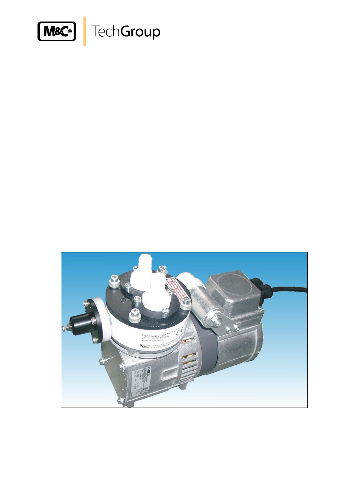
Operating Manual
Diaphragm pump series MP
®
Version MP47-Z-BPR150
Gas sampling and gas conditioning technology 6-1.1.7-ME
Page 2

2
Contents
1 General information ................................................................................................................ 4
2 Declaration of conformity ....................................................................................................... 4
3 Safety instructions .................................................................................................................. 5
4 Warranty ................................................................................................................................... 5
5 Used terms and signal indications ........................................................................................ 6
6 Introduction .............................................................................................................................. 6
7 Range of application ............................................................................................................... 7
8 Ambiance ................................................................................................................................. 7
8.1 Safety ................................................................................................................................. 7
9 Technical data .......................................................................................................................... 8
10 Receipt of goods and storage ................................................................................................ 9
11 Instructions for installation .................................................................................................. 10
11.1 Mechanical installation ..................................................................................................... 11
11.2 Electrical connection ....................................................................................................... 11
11.3 Pneumatical connection ................................................................................................... 13
12 Supply connections .............................................................................................................. 13
12.1 Hose connections ............................................................................................................. 13
13 Start up ................................................................................................................................... 14
14 Closing down ......................................................................................................................... 14
15 Maintenance ........................................................................................................................... 15
15.1 Change of the pump diaphragm ....................................................................................... 16
15.2 Change of the valve plate ................................................................................................. 16
15.3 Cleaning ........................................................................................................................... 17
16 Trouble shooting ................................................................................................................... 18
17 Spare parts list ....................................................................................................................... 19
18 Annex ...................................................................................................................................... 19
List of Illustrations
Illustration 1 Construction pump head ............................................................................................ 9
Illustration 2 Dimensions (mm) MP47-Z-BPR150 ........................................................................ 11
Illustration 3 Electrical connection of the pump ............................................................................ 12
Illustration 4 Sectional drawing ..................................................................................................... 15
Gas sampling and gas conditioning technology 6-1.1.7-ME
Page 3

3
This operating manual does not claim completeness and may be
subject to technical modifications.
© 06/2007 M&C TechGroup Germany GmbH. Reproduction of this
document or its content is not allowed without permission from M&C.
MP® is a registered trade mark.
2nd Edition: 03/2011
Dear customer,
we have made up this operating manual in such a way that all necessary information about the product can be found and understood quickly and easily.
Should you still have any question, please do not hesitate to contact M&C directly or go through your
appointed dealer. Respective contact addresses are to be found in the annex to this operating manual.
Please also contact our homepage www.mc-techgroup.com for further information about our products. There, you can read or download the data sheets and operating manuals of all M&C products as
well as further information in German, English and French.
Gas sampling and gas conditioning technology 6-1.1.7-ME
Page 4

4
Head Office
M&C TechGroup Germany GmbH Rehhecke 79 40885 Ratingen Germany
Telephone: 02102 / 935 - 0
Fax: 02102 / 935 - 111
E - mail: info@mc-techgroup.com
www.mc-techgroup.com
1 GENERAL INFORMATION
The product described in this operating manual has been examined before delivery and left our works
in perfect condition related to safety regulations. In order to keep this condition and to guarantee a
safe operation, it is important to heed the notes and prescriptions made in this operating manual.
Furthermore, attention must be paid to appropriate transportation, correct storage, as well as professional installation and maintenance work.
All necessary information a skilled staff will need for appropriate use of this product are given in this
operating manual.
2 DECLARATION OF CONFORMITY
CE - Certification
The product described in this operating manual complies with the following EC directives:
EMV Instruction
The requirements of the EC directive 2004/108/EC “Electromagnetic compatibility” are met.
Low Voltage Directive
The requirements of the EC directive 2006/95/EC “Low Voltage Directive“ are met.
The compliance with this EC directive has been examined according to DIN EN 61010.
Declaration of Conformity
The EU declaration of conformity can be downloaded from the M&C homepage or directly requested
from M&C.
Gas sampling and gas conditioning technology 6-1.1.7-ME
Page 5

5
3 SAFETY INSTRUCTIONS
Please take care of the following basic procedures when mounting, starting up or operating
this equipment:
Read this operating manual before starting up and use of the equipment. The information and warnings given in this operating manual must be heeded.
Any work on electrical equipment is only to be carried out by trained specialists as per the regulations
currently in force.
Attention must be paid to the requirements of VDE 0100 when setting high-power electrical units with
nominal voltages of up to 1000 V, together with the associated standards and stipulations.
Check the details on the type plate to ensure that the equipment is connected to the correct mains
voltage.
Protection against touching dangerously high electrical voltages:
Before opening the equipment, it must be switched off and hold no voltages. This also applies to any
external control circuits that are connected.
The device is only to be used within the permitted range of temperatures and pressures.
Check that the location is weather-protected. It should not be subject to either direct rain or moisture.
The diaphragm pumps MP47-Z-BPR150 must not be used in hazardous areas.
Installation, maintenance, monitoring and any repairs may only be done by authorized personnel with
respect to the relevant stipulations.
4 WARRANTY
If the equipment fails, please contact M&C directly or go via your appointed M&C dealer.
We offer a one year warranty as of the day of delivery as per our normal terms and conditions of sale
and assuming technically correct operation of the device. Consumables are hereby excluded. The
terms of the warranty cover repair at the factory at no cost or the replacement at no cost of the
equipment free ex user location. Reshipments must be sent in a sufficient and proper protective
packaging.
Gas sampling and gas conditioning technology 6-1.1.7-ME
Page 6
6
DANGER!
This means that death, severe physical injuries and/or important
material damages will occur in case the respective safety measures
are not fulfilled.
WAR NI NG!
This means that death, severe physical injuries and/or important
material damages may occur in case the respective safety measures are not fulfilled.
CAUTION!
This means that minor physical injuries may occur in case the
respective safety measures are not fulfilled.
CAUTI ON !
Without the warning triangle means that a material damage may
occur in case the respective safety measures are not met.
ATTEN TI ON
This means that an unintentional situation or an unintentional status
may occur in case the respective note is not respected.
NOTE!
These are important information about the product or parts of the
operating manual which require user’s attention.
SKILLED STAFF
These are persons with necessary qualification who are familiar with
installation, use and maintenance of the product.
5 USED TERMS AND SIGNAL INDICATIONS
6 INTRODUCTION
The diaphragm pump MP47-Z-BPR150 is suitable for the 100 % oil-free delivery of corrosive gases
with changing pressure conditions. The capacity and construction of the pump is especially designed
Gas sampling and gas conditioning technology 6-1.1.7-ME
Page 7

7
NOTE!
The diaphragm pumps of the series MP47 must not deliver liquids.
for the problems in the analyze technique. The pump is gas-tight and operates without any maintenance.
7 RANGE OF APPLICATION
All sample contacting parts of the diaphragm pump MP47-Z-BPR150 are made of PTFE, PVDF and
Viton or Kalrez. The lifted gas remains analytically pure due to the fact that the pump works absolutely
without any lubricant. A special diaphragm and valve system guaranties a long life time and no maintenance is necessary. The pump is available for 230V or 115V.
One problem in the analyze technique, when lifting gases via filters, is that the filters are clogged after
a longer period of time. This causes an increasing differential pressure above the filter and subsequently, a higher suction pressure for the pump is necessary. This, however, results in a decrease of
the adjusted pump capacity.
In order to avoid this negative influence, the M&C diaphragm pump MP47-Z-BPR150 is equipped with
a fully adequate bypass admission pressure regulator inside the pump head. Independent from the
changing entry pressure, the bypass admission pressure regulator keeps the pressure at the pump
outlet constant, so that the adjusted pump capacity resulting thereof remains constant as well.
For example, the entry pressure may vary from 0,46 bar abs. to 1,1 bar abs. for a pump capacity of
250Nl/h.
The outlet pressure is adjusted at works to 200mbar overpressure (adjustable up to 300mbar).
• Delivery of gases and vapors with a temperature of - 30 °C to + 80 °C.
• Maximum admissible operating overpressure, final vacuum, pump capacity: see technical data.
• Before using the pump in unknown mediums, check the compatibility of the pump head and valve
materials with the respective medium.
8 AMBIANCE
Please keep the following ambient conditions during operation:
Range of ambient temperature during operation: -10 °C to + 40 °C.
The pumps must be protected against water and dust effects.
During operation, a sufficient supply of cooling air must be provided.
8.1 SAFETY
The pumps MP47-Z-BPR150 are executed according to protection IP20 and do not provide any protection against touching and foreign bodies.
Gas sampling and gas conditioning technology 6-1.1.7-ME
Page 8

8
WARN IN G!
It is important to provide protection for persons against contact
with life parts (e.g. electrical connections, eventually motor windings) or moving parts (e.g. fan).
WARN IN G!
Aggressive medium is possible.
Wear protective glasses and appropriate protective clothes during
disassembly, repair or cleaning the pump!
NOTE!
Components to be connected to the pump must be designed
according to the pneumatic performance of the pump (see technical data).
Take care that safety regulations are observed when connecting
the pump to the power supply.
Specific safety instructions concerning the lifted medium are to
be observed.
Diaphragm pump
MP47-Z-
BPR150-Viton
MP47-Z-
BPR150-Viton
MP47-Z-
BPR150-Kalrez
MP47-Z-
BPR150-Kalrez
Part No.
02 P 1160
02 P 1160a
02 P 1165
02 P 1165a
The pumps are not protected against effects from water. If applicable, respective protection measures
must be taken before starting the pump.
The pumps must only be used for their intended purpose.
9 TECHNICAL DATA
Gas sampling and gas conditioning technology 6-1.1.7-ME
Page 9

9
Voltage
230V 50Hz
115V 60Hz
230V 50Hz
115V 60Hz
Protection class
IP 20 - DIN 40050
Pump capacity max.
6,6 l/min* in the range of adjustment (outlet pressure)
Operating pressure
max.*
1,1 bar abs.
Operating pressure
min.**
0,46 bar abs. for 250Nl/h / 0,62 bar abs.
for 400Nl/h (outlet pressure 1,20 bar abs.)
Outlet pressure
1,15 – 1,3 bar abs. / at works 1,20 bar abs.
Gas temperature
-30 to +80°C
Ambient temperature
-10 to +40°C
Storage temperature
-15 to +60°C
Power consumption
110W
Current consumption
0,75A
1,7A
0,75A
1,7A
Gas connections
G1/4" i DIN ISO 228/1
Electrical standard
EN 61010 Teil 1
Material of sample contacting parts
PTFE, PVDF, Viton
PTFE, PVDF, Kalrez
Weight
4,6 Kg
Material mark according to ISO 1629 und 1043.1
* Maximum operating pressure for a constant outlet pressure and as a result a constant flow rate of the mea-
suring gas.
** The minimum operating pressure that still guarantees a constant pump capacity is changing according to the
necessary gas volume flow adjusted behind the pump and to the outlet pressure adjusted on the pressure
regulator. The lower the necessary gas volume flow and the outlet pressure, the lower is the minimal possible operating pressure that still guarantees a constant outlet pressure and therefore a constant sample gas
volume flow.
Illustration 1 Construction pump head
10 RECEIPT OF GOODS AND STORAGE
• Remove carefully the diaphragm pump and any accessories from the packaging and check im-
mediately against the delivery note whether the consignment is complete.
Gas sampling and gas conditioning technology 6-1.1.7-ME
Page 10

10
NOTE!
The equipment should be stored in a protected, frost-free room!
NOTE!
Please comply with the respective safety instructions regarding
the samples to be delivered.
In order to avoid any heat accumulation, the pump should be
installed away from heat sources and should also be freely ventilated.
When mounting the pump outside, it must be installed in a protective housing, frost-protected in winter and sufficiently aerated in
summer. Direct solar radiation must be avoided.
WARN IN G
It is very important to provide a protection for persons against
contact of live parts (eg. electrical connections) or moving parts.
It must also be taken care to protect the pump against penetration
of foreign bodies.
NOTE!
Pumps have mechanical moving parts that can induce vibrations.
To prevent damages at the pump or at peripheral components /
facilities as well as minimizing noise development an appropriate
vibration decoupling is necessary. For this M&C can deliver e.g.
anti-vibration pads.
This explicit is also valid for the connection of the sample lines at
the pump head.
• Check the goods for any damage incurred during transport and, if necessary, inform your trans-
port insurer of any damage.
11 INSTRUCTIONS FOR INSTALLATION
During installation, the safety instructions as well as those for accident prevention must be heeded,
also with regard to the later operation. Further, the safety instructions under chapter 3 must be kept.
The pumps MP47-Z-BPR150 are executed according to protection type IP20 and, therefore, do not
supply any protection against contact and foreign bodies.
Gas sampling and gas conditioning technology 6-1.1.7-ME
Page 11

11
The diaphragm pumps MP47-Z-BPR150 must not be used in hazardous locations.
WARN IN G!
Wrong supply voltage can destroy the equipment.
When connecting the pump, please ensure that the supply voltage
is identical with the information provided on the type plate! A
deviation of max. +6 % or -10 % from the indication on the type
plate is allowed.
G1/4"
34
6
133 71
263
165
11
90
173
11.1 MECHANICAL INSTALLATION
For the mounting dimensions, see illustration 7.
Mount the pumps in such a way that the ventilator can suck sufficient cooling air.
Make sure that nobody can touch the ventilator. Mount the pumps at the highest point in the
system and/or mount them with the pump head downwards in order to avoid the collection of
condensate inside the pump head. This measure increases the service life.
Illustration 2 Dimensions (mm) MP47-Z-BPR150
11.2 ELECTRICAL CONNECTION
When executing electrical mounting works, please respect the appropriate safety instructions. Before
connecting the pump, take care that the electrical connection is voltage-free.
Gas sampling and gas conditioning technology 6-1.1.7-ME
Page 12

12
NOTE!
Attention must be paid to the requirements of IEC 364 (DIN VDE
0100) and its associated standards and stipulations when setting
high-power electrical units with nominal voltages of up to 1000V!
The main circuit of the pump type MP47 ... (230 V) must be
equipped with a protective motor switch 0,63 – 1 A corresponding
to the nominal voltage (over current protection).
The main circuit of the pump type MP47 ... (115 V) must be
equipped with a protective motor switch 1 – 1,6 A corresponding
to the nominal voltage (over current protection).
The ground conductor has to be connected to the pump motor.
A device for separating the pump motor from the electrical supply voltage must be mounted
into the electrical installation (according to EN 60335-1).
Mount the pumps in such a way that any contact of the life parts (eg. electrical connection,
motor windings) is impossible.
Illustration 3 Electrical connection of the pump
Remove the lid with PG screwing;
Insert the connecting cable though PG and connect it according to figure 8. The connections
are indicated inside the connecting box.
Gas sampling and gas conditioning technology 6-1.1.7-ME
Page 13

13
NOTE!
The diaphragm pump is only to be used under the special conditions
specified in the technical data. Do not place the diaphragm pump near
to heat sources and provide sufficient aeration in order to avoid heat
accumulation.
When mounting the pump outside, it must be installed in a protecting
housing that is frost-protected in winter and sufficiently aerated in
summer. Direct solar radiation must be avoided.
NOTE!
Do not twist the valve body when mounting the hose connections because it can influence the sampling capacity of the pump. Do not interchange the hose connections for the sample gas inlet and outlet. The
connections are identified accordingly. After all lines being connected,
check whether the connection is tight.
The tightness of the connection can only be guaranteed if the border of
the connection hose is straight (use a hose cutter).
11.3 PNEUMATICAL CONNECTION
Remove the protection plug from the gas connection thread (thread size G1/4”).
Accessories such as tube connections are screwed into the connection thread by means of a
sealing tape (when using the screw fitting from M&C, no sealing tape is necessary).
Connect the suction and pressure line.
Mount the suction and pressure lines in a way to avoid condensate flowing into the pump.
12 SUPPLY CONNECTIONS
12.1 HOSE CONNECTIONS
The connection is made on top of the pump. There are standard connections with G1/4” inside
threads.
When connecting the hoses to the hose connection fittings to be supplied as option, please note the
following:
Loosen the sleeve nut of the clamping-ring threaded joint by turning to the left. Take care that
the nut is removed carefully from the body of the threaded joint to avoid losing the clamping
ring which is placed loose in the nut.
Push the sleeve nut over the connection hose/tube.
Push the clamping ring onto the connection hose/tube with the thicker bulge pointing to the
nut.
Push the hose/tube onto the supporting nipple in the threaded joint. Tighten the sleeve nut by
hand.
The hose/tube is now mounted in such a way that it cannot slip and is resistant to pressure.
Connection fittings for DN 4/6 or DN 6/8 are optionally available from M&C.
Gas sampling and gas conditioning technology 6-1.1.7-ME
Page 14

14
NOTE!
The location where the pump is installed must be free of frost also
when it is not in use.
WARN IN G!
Aggressive condensate possible.
Wear safety glasses and appropriate protection clothes when
dismounting, repairing or cleaning the pump!
13 START UP
Before starting up, please observe the safety measures related to the installation and the process!
Also respect the respective safety prescriptions and measures related to the sampled gases. Before
pumping the medium, please check the compatibility of the gas with the materials of pump head,
diaphragm and valves (for pump materials: see technical data).
The following steps have to be executed for the initial start up:
The pump must not start against pressure or vacuum.
When switching on the pump, the pressure in the lines must be atmospheric. The same is
valid when the pump is restarted after a power cut off for a short period.
The maximum permissible operating pressure (see technical data, chapter 9) must not be ex-
ceeded.
To prevent the maximum permissible operating pressure being exceeded, restriction or control
of the gas flow should only be carried out in the suction line.
If restriction or control of gas flow is made on the pressure side, ensure that the maximum
permissible operating pressure is not exceeded.
When the pump is at a standstill, the lines must have got the normal atmospheric pressure.
Diaphragm and valve plates are the only parts subject to wear. Wear is usually indicated by a
drastic reduction in the pneumatic performance. When replacing parts, proceed as described
in chapter 15.
Ambient conditions: see technical data, chapter 9.
14 CLOSING DOWN
No special measures are to be taken when closing down the pump.
Gas sampling and gas conditioning technology 6-1.1.7-ME
Page 15

15
WARN IN G!
Dangerous tension.
Before carrying out any maintenance on the pump, disconnect the
pump from the supply voltage!
WARNI NG !
Aggressive medium residues possible.
Wear safety glasses and appropriate protection clothes when
dismounting, repairing or cleaning the pump!
Valve, suction side
Valve, pressure side
15 MAINTENANCE
Before the maintenance work is carried out, it is necessary that the specific safety procedures
pertaining to the system and operational process be observed!
Diaphragm and valve plates are the only parts subject to wear. They are simply to be exchanged.
Illustration 4 Sectional drawing
Parts and tools required:
Gas sampling and gas conditioning technology 6-1.1.7-ME
Page 16

16
NOTE!
It is recommended to change the valve plates and diaphragms always
at the same time.
Valve plates, sealing rings (2 per each pump head) and structured diaphragms (1 per pump
head) according to spare parts list, chapter 17.
Change the diaphragm(s) and the valve plates in the following sequence:
15.1 CHANGE OF THE PUMP DIAPHRAGM
Mark the position between the housing A , the diaphragm head B and the pressure plate C
with a pencil.
Loosen the 4 hexagon screws H and remove the pressure plate C and the diaphragm head B.
Unscrew the diaphragm K by hand out of the tapping hole of the rod L (counter-clockwise).
Loosen the 4 screws M and remove the cover N.
Screw in the new diaphragm K into the rod L and tighten by hand.
Turn the fly wheel P until rod L is in central position. Control that the bulge of the diaphragm K
is placed inside the groove of the housing A.
Put on the diaphragm head B and the pressure plate C according to the pencil marks. Tighten
the 4 hexagon screws H crosswise until the disc springs R are flat. Control the easy running
when turning the disk flywheel P and mount the cover N.
15.2 CHANGE OF THE VALVE PLATE
Loosen the 6 hexagon screws D and remove the pressure rings E . Loosen the valve bodies F
and G .
Replace the O-ring S on the valve body F (pressure side) by a new one. Remove the valve
plate T and replace it by a new one. Take care that the protection ring U is placed in the right
position and that the 6 supports of the valve plate T show upwards. Screw the valve body F in
again and tighten moderately.
Replace the O-ring S on the valve body G (suction side) by a new one. Remove the valve
plate T and replace it by a new one. Take care that the protection ring U is placed in the right
position and that the 6 supports of the valve plate T show downwards. Screw the valve body G
in again and tighten moderately.
Put on the pressure rings E and tighten the 6 hexagon screws D.
Gas sampling and gas conditioning technology 6-1.1.7-ME
Page 17

17
WARNI NG !
Aggressive medium residues possible.
Wear safety glasses and proper protection clothes when disassembling, repairing or cleaning the pump!
15.3 CLEANING
When exchanging the valve plates and diaphragms, please check all parts for dirt and clean
them if necessary before assembling the pump head.
As far as possible, clean the parts with a dry cloth. Do not use any solvents for cleaning be-
cause they can attack the plastic parts. If oil free compressed air is available, blow the parts
out with it.
Please read our recommendations for spare parts in the spare parts list, chapter 17.
Gas sampling and gas conditioning technology 6-1.1.7-ME
Page 18

18
Problem/Indication
Possible cause
Action/Check
Pump does not lift.
No mains supply.
Check power supply; check the correct fitting
of the mains cable.
Connections of lines are
blocked.
Remove blockade.
The internal or an external
valve is closed or a filter is
blocked.
Open the valve or clean the dirty/blocked
filter.
Liquid (condensate) is collected inside the pump head.
Operate the pump with air for a few minutes;
mount it at the highest point of the system.
Pump capacity,
pressure or vacuum
are too low.
Diaphragm or valve plates are
worn out.
Exchange the respective parts.
Compare the actual performance with the technical data
in chapter 9.
Pump is possibly not designed for this condition.
The vacuum on the suction
side is too high.
Pump is not designed for this condition.
The cross section of pneumatic lines or connected components is too small, or they are
restricted.
To measure the performance, disconnect the
pump from the system; even one single line
with a too small cross section can influence
significantly the measuring value, the same
is valid for a valve installed in the system.
A leak on the connections, the
lines or the pump head. Diaphragms or valve plates are
defective or head parts are
dirty.
Insulate the leak. Tighten the screws.
Change the defective parts, clean or exchange the dirty parts.
NOTE!
Before any work on the pump, disconnect the supply voltage and check
that no parts are alive.
16 TROUBLE SHOOTING
Before working on the pump, disconnect the power supply securely. Check that the lines are not alive.
Gas sampling and gas conditioning technology 6-1.1.7-ME
Page 19

19
Diaphragm pump MP47-Z-BPR150
V) Consumable parts (E) Recommended spare parts (T) Spare parts
Recommended quantity after
operation of the pump [years]
Part No..
Description
V/E/T 1 2
3
90P1108
Back-up ring type U f. valve chamber MP47
E - -
1
90P1105
Diaphragm type K f. MP47
Material: Viton, PTFE coated
E 1 2
3
90P1110
Valve plate type T for MP47, 1 piece
Material: PTFE (2 pcs. required)
E 2 4
6
90P1111
Valve body type F/G 1/4”i for MP47
Material: PTFE
E 1 2
3
90P3025
Rod for MP47 type L
T - -
1
90P4020
Regulation valve BPR 150 for MP47-Z-BPR150
Viton
T - -
1
90P4022
Regulation valve BPR 150 for MP47-Z-BPR150
Kalrez
T - -
1
PVDF Male connectors with G thread (ISO 1010031)
05V1045
Male connector DN 4/6-G1/8”
Material: PVDF
T - -
2
05V1050
Male connector DN 6/8-G1/8”
Material: PVDF
T - -
2
05V6600
Ferrule DN 4/6, PVDF
T 2 2
4
05V6602
Ferrule DN 6/8, PVDF
T 2 2
4
05V6605
Union nut DN 4/6, PVDF
T 2 2
4
05V6607
Union nut DN 6/8, PVDF
T 2 2
4
17 SPARE PARTS LIST
Wear, tear and replacement part requirements depend on specific operating conditions.
The recommended quantities are based on experience and are not binding.
18 ANNEX
For additional information, please look on our home page under:
www.mc-techgroup.com
Gas sampling and gas conditioning technology 6-1.1.7-ME
 Loading...