

Page 1
Operating Manual
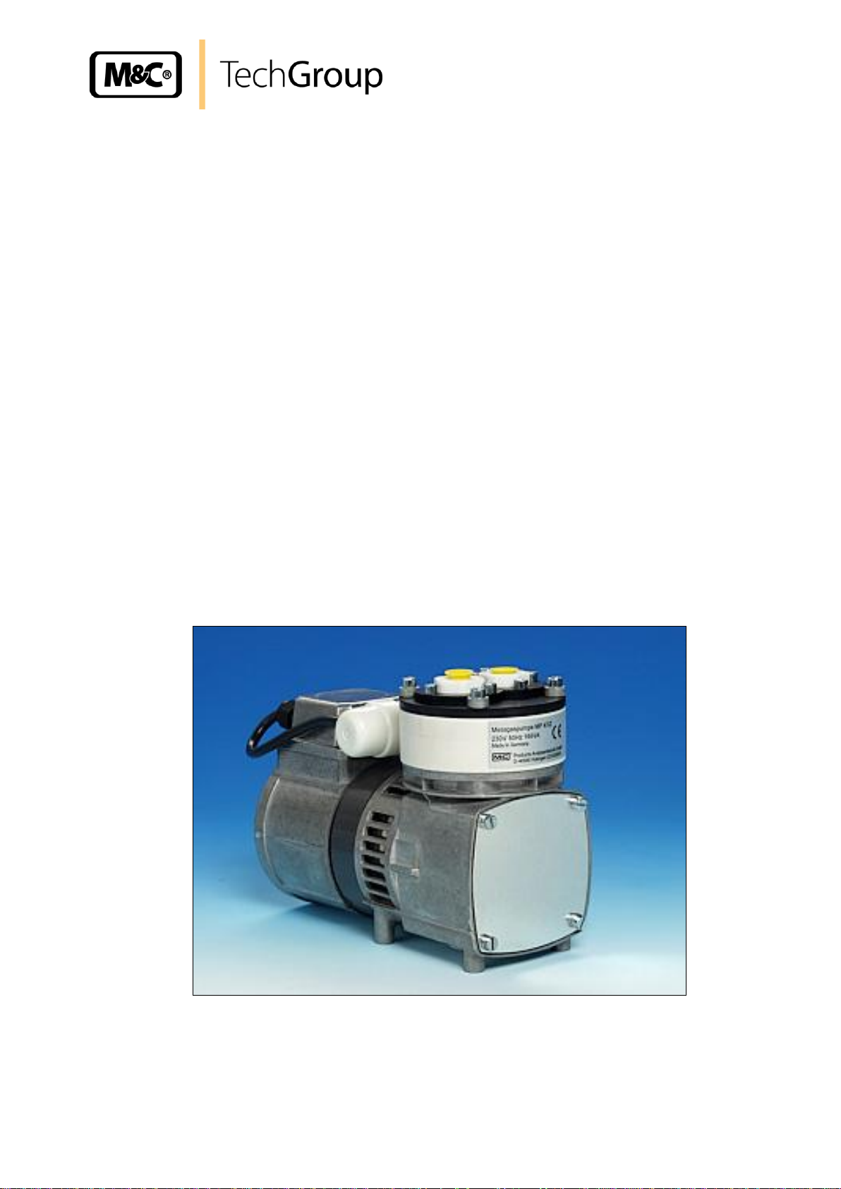
Diaphragm-sample pump series MP
®
Version MP47, MP47/R, MP47-Z, MP47-Z/R, MP47/D
Gas sampling and gas conditioning technology 6-1.1.1-ME
Page 2

2
List of content
1 General information ................................................................................................................ 4
2 Declaration of conformity ....................................................................................................... 4
3 Safety instructions .................................................................................................................. 5
4 Warranty ................................................................................................................................... 5
5 Used terms and signal indications ........................................................................................ 6
6 Introduction .............................................................................................................................. 7
7 Description ............................................................................................................................... 7
8 Ambient conditions ................................................................................................................. 8
8.1 Safety ..................................................................................................................................... 8
9 Technical data .......................................................................................................................... 9
10 Version MP47/R and MP47-Z/R with integrated needle valve type .../R for flow .................
adjustment ............................................................................................................................. 10
11 Version MP47 .../D with a double diaphragm safety system/ diaphragm ............................
breakage monitoring system ................................................................................................ 11
11.1 Application ........................................................................................................................ 11
11.2 Description ....................................................................................................................... 11
12 Flow sensor LPH 125-1-A-SPST incl. connection set MP47 .../D mounted on ....................
pump MP47 .../D ................................................................................................ ..................... 12
13 Receipt of goods and storage .............................................................................................. 12
14 Installation instructions ........................................................................................................ 13
14.1 Mechanical ....................................................................................................................... 13
14.2 Electrical ........................................................................................................................... 14
14.3 Pneumatic ........................................................................................................................ 15
15 Supply line connections ....................................................................................................... 16
15.1 Hose-/tube connections .................................................................................................... 16
16 Start up ................................................................................................................................... 16
17 Closing down ......................................................................................................................... 17
18 Maintenance ........................................................................................................................... 17
18.1 Exchange of the diaphragm ............................................................................................. 18
18.2 Exchange of the valve plates ........................................................................................... 19
18.3 Cleaning ........................................................................................................................... 19
19 Trouble shooting ................................................................................................................... 20
20 Spare parts list ....................................................................................................................... 21
21 Annexe .................................................................................................................................... 22
List of illustrations
Figure 1 Pump capacity MP47 ........................................................................................................ 7
Figure 2 Pump type MP47/R ......................................................................................................... 10
Figure 3 Flow capacity type MP47/R ............................................................................................. 10
Figure 4 Flow capacity type MP47-Z/R ......................................................................................... 10
Figure 5 Pump MP47 .../D with the standard motor ...................................................................... 11
Figure 6 Pump MP47 .../D with flow sensor .................................................................................. 12
Figure 7 Dimensions (mm) pump MP47 ........................................................................................ 14
Figure 8 Electrical connection of the pump ................................................................................... 15
Figure 9 Sectional drawing pump MP47 ........................................................................................ 18
Gas sampling and gas conditioning technology 6-1.1.1-ME
Page 3

3
This Operating Manual does not claim completeness and may be
subject to technical modifications.
© 12/2001 M&C TechGroup Germany GmbH. Reproduction of this
document or its content is not allowed without permission from M&C.
MP® is a registered trade mark.
4th Edition: 03/2011
Dear customer,
we have made up this operating manual in such a way that all necessary information about the product can be found and understood quickly and easily.
Should you still have any question, please do not hesitate to contact M&C directly or go through your
appointed dealer. Respective contact addresses are to be found in the annexe to this operating manual.
Please also contact our homepage www.mc-techgroup.com for further information about our products. There, you can read or download the data sheets and operating manuals of all M&C products as
well as further information in German, English and French.
Gas sampling and gas conditioning technology 6-1.1.1-ME
Page 4

4
Head Office
M&C TechGroup Germany GmbH Rehhecke 79 40885 Ratingen Germany
Telephone: 02102 / 935 - 0
Fax: 02102 / 935 - 111
E - mail: info@mc-techgroup.com
www.mc-techgroup.com
1 GENERAL INFORMATION
The product described in this operating manual has been examined before delivery and left our works
in perfect condition related to safety regulations. In order to keep this condition and to guarantee a
safe operation, it is important to heed the notes and prescriptions made in this operating manual.
Furthermore, attention must be paid to appropriate transportation, correct storage, as well as professional installation and maintenance work.
All necessary information a skilled staff will need for appropriate use of this product are given in this
operating manual.
2 DECLARATION OF CONFORMITY
CE - Certification
The product described in this operating manual complies with the following EC directives:
EMV-Instruction
The requirements of the EC directive 2004/108/EC “Electromagnetic compatibility“ are met.
Low Voltage Directive
The requirement of the EC directive 2006/95/EC “Low Voltage Directive“ are met.
The compliance with this EC directive has been examined according to DIN EN 61010.
Declaration of conformity
The EU Declaration of conformity can be downloaded from the M&C homepage or directly requested
from M&C.
Gas sampling and gas conditioning technology 6-1.1.1-ME
Page 5

5
3 SAFETY INSTRUCTIONS
Please take care of the following basic safety procedures when mounting, starting up or operating this equipment:
Read this operating manual before starting up and use of the equipment. The information and warnings given in this operating manual must be heeded.
Any work on electrical equipment is only to be carried out by trained specialists as per the regulations
currently in force.
Attention must be paid to the requirements of VDE 0100 (IEC 364) when setting high-power electrical
units with nominal voltages of up to 1000 V, together with the associated standards and stipulations.
Check the details on the type plate to ensure that the equipment is connected to the correct mains
voltage.
Protection against touching dangerously high electrical voltages:
Before opening the equipment, it must be switched off and hold no voltages. This also applies to any
external control circuits that are connected.
The device is only to be used within the permitted range of temperatures and pressures.
Check that the location is weather-protected. It should not be subject to either direct rain or moisture.
The Diaphragm-sample pumps MP47, MP47/R, MP47-Z, MP47-Z/R, MP47/D must not be used in
hazardous areas.
Installation, maintenance, monitoring and any repairs may only be done by authorized personnel with
respect to the relevant stipulations.
4 WARRANTY
If the equipment fails, please contact M&C directly or else go through your M&C authorised dealer.
We offer a one year warranty as of the day of delivery as per our normal terms and conditions of sale,
and assuming technically correct operation of the unit. Consumables are hereby excluded. The terms
of the warranty cover repair at the factory at no cost or the replacement at no cost of the equipment
free ex user location. Reshipments must be send in a sufficient and proper protective packaging.
Gas sampling and gas conditioning technology 6-1.1.1-ME
Page 6
6
DANGER!
This means that death, severe physical injuries and/or important
material damages will occur in case the respective safety measures
are not fulfilled.
WA R NI N G!
This means that death, severe physical injuries and/or important
material damages may occur in case the respective safety measures are not fulfilled.
CARE!
This means that minor physical injuries may occur in case the
respective safety measures are not fulfilled.
CA R E!
Without the warning triangle means that a material damage may
occur in case the respective safety measures are not met.
AT T EN T IO N !
This means that an unintentional situation or an unintentional status
may occur in case the respective note is not respected.
NOTE!
These are important information about the product or parts of the
operating manual which require user’s attention.
SKILLED STAFF
These are persons with necessary qualification who are familiar with
installation, use and maintenance of the product.
5 USED TERMS AND SIGNAL INDICATIONS
Gas sampling and gas conditioning technology 6-1.1.1-ME
Page 7
7
0
50
100
150
200
250
300
350
400
450
0,4
0,5
0,6
0,7
0,8
0,9 1 1,2
1,4
1,6
1,8 2 2,2
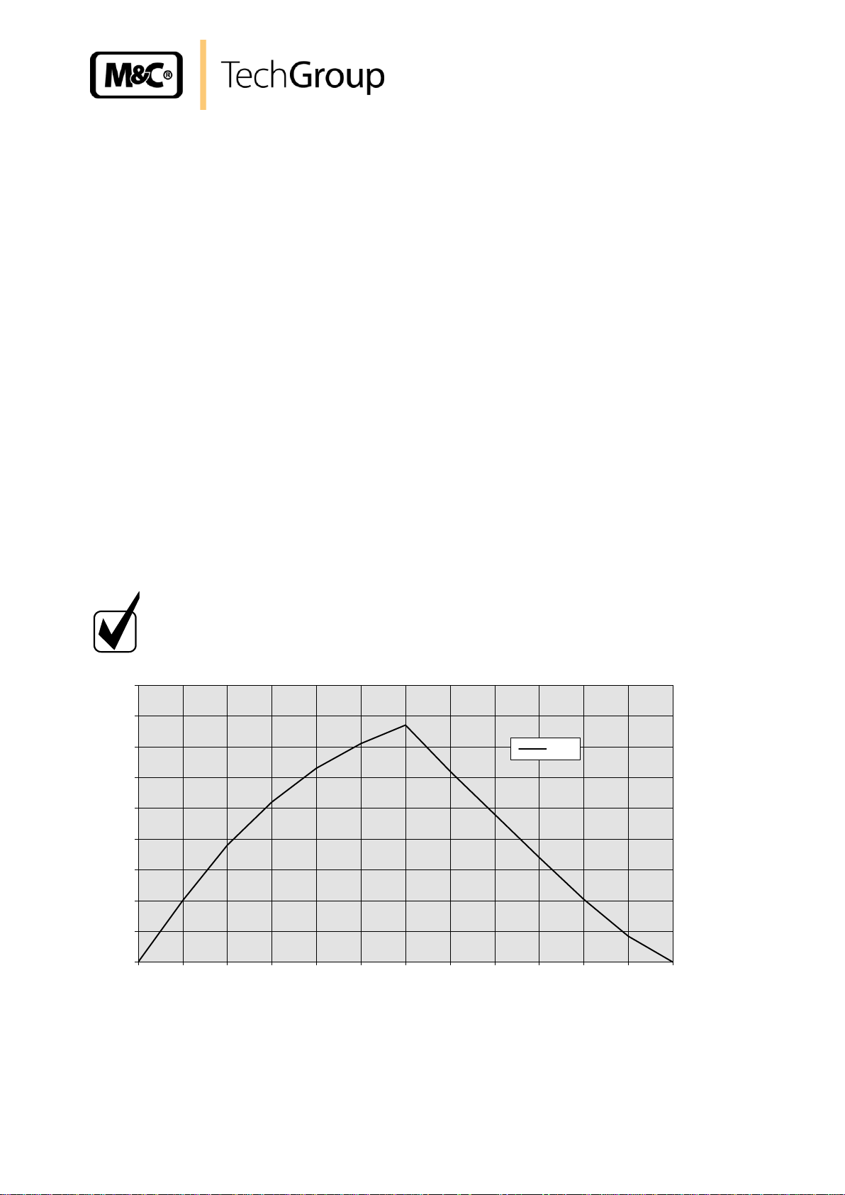
l/hr
MP47
bar abs.
NOTE!
The diaphragm pump series MP47 ... are not allowed for liquid medium.
6 INTRODUCTION
This diaphragm pump MP47 ... is suitable for corrosive gases. It is constructed especially for problems in the analysis technique.
7 DESCRIPTION
The pump MP47 has a PTFE-head. All sample contacting parts are out of PTFE. The pump works
absolutely lubricant free, so gases remain analytically unchanged. Due to a special diaphragm and
valve system, the pump operates maintenance-free.
The MP47 ... is available in 230 V or 115 V and can be equipped with an EEx motor for applications in
hazardous areas as well.
The standard MP47 ... is designed for normal applications at a maximum gas flow of 6 l/min. Up to
flow rates of 17 l/min we recommend the type MP47-Z.
With the option MP .../R a needle valve is build into the pump-head to adjust the flow rate (see data
sheet 6-1.1.3).
M&C provides for the series MP47 ... pump as option a diaphragm breakage monitoring. MP47 .../D is
equipped with a special double-membrane safety system (see 6-1.1.5).
Maximum temperature for medium during operating: -30 °C ... +80 °C.
The pump must be protected from the effectes of dust and water.
Before use please check the compatibility of the material.
Figure 1 Pump capacity MP47
Gas sampling and gas conditioning technology 6-1.1.1-ME
Page 8
8
WA R NI N G!
It is therefore essential to provide protection for persons against
contact with live parts (e.g. electrical connections, motor windings) and moving parts (e.g. fan). Protection against the entry of
foreign bodies must also be provided.
WA R NI N G!
Aggressive medium is possible.
Wear protective glasses and proper protective clothing during
disassembly, repair or cleaning!
NOTE!
Components connected to the pump must be designed according
to the pneumatic performance of the pump (see technical data).
Take care that safety regulations are observed when connecting
the pump to the power supply. Specific safety instructions con-
cerning sample must be observed.
8 AMBIENT CONDITIONS
When the pump is operating the following ambient conditions must be maintained:
• Ambient temperature during operating: -10 °C .... + 40 °C.
• The pump must be protected from the effects of dust and water.
• During operating an adequate supply of air for cooling must be provided.
8.1 SAFETY
The protection class of the pumps MP47/MP47-Z is IP20 and so offer no protection against contact or
foreign bodies.
The pumps have no protection against water. In this case too, as far as is relevant, measures to protect the pump must be taken before start-up.
The pumps may only be used for their intended purpose.
Gas sampling and gas conditioning technology 6-1.1.1-ME
Page 9

9 TECHNICAL DATA
Diaphragm pump
MP47 /230V
MP47 /115V
MP47-Z /230V
MP47-Z /115V
Part No.
02 P 1000
02 P 1000a
02 P 1100
02 P 1100a
Power supply
230V 50Hz
115V 60Hz
230V 50Hz
115V 60Hz
Degree of protection
IP 20 - DIN 40050
Capacity max.
6,0 l/min* without pressure
0,85 / 1,25 bar abs., on suc-
tion/pressure side: 2,5 l/min
17 l/min* without pressure
Operating pressure
0,4 to 2,2 bar abs.
0,1 to 2,5 bar abs.
Sample temperature
-30 to +80°C
Ambient temperature
-10 to +40°C
Storage temperature
-15 to +60°C
Power consumption
110W
Current consumption
0,75A
1,7A
0,75A
1,7A
Gas connections
G1/4" i DIN ISO 228/1
Electrical standard
EN 61010 part 1
Material of sample contacting parts
PTFE
Weight
4,4 Kg
Material mark according to ISO 1629 and 1043.1
* Litre at standard conditions
9
Gas sampling and gas conditioning technology 6-1.1.1-ME
Page 10

10
Needle valve
Pump head
Sample gas
10 VERSION MP47/R AND MP47-Z/R WITH INTEGRATED NEEDLE VALVE TYPE
.../R FOR FLOW ADJUSTMENT
The integrated needle valve in the pump head is an internal bypass and allows to adjust the flow
capacity . In case of the optimal needle form, flow adjustment in a wide range is possible. All parts in
contact with sample are made from PTFE and PVDF. No O-rings are necessary.
Figure 2 Pump type MP47/R
Figure 3 Flow capacity type MP47/R Figure 4 Flow capacity type MP47-Z/R
Gas sampling and gas conditioning technology 6-1.1.1-ME
Page 11

11
66
18
80
20
110
180
G1/4"
4xM6 10 tief
34
124
G1/8
11 VERSION MP47 .../D WITH A DOUBLE DIAPHRAGM SAFETY SYSTEM/
DIAPHRAGM BREAKAGE MONITORING SYSTEM
11.1 APPLICATION
There are some applications - for example when processing with strong aggressive, high toxic or
hydrocarbon contaminated gases, it is necessary to install a high level safety system. For these applications, it is important to monitore continuously the tightness of the pump diaphragm.
11.2 DESCRIPTION
M&C provides for the series MP47... pump as option a diaphragm breakage monitoring. Below the
pump diaphragm, a monitoring area integrated as a pressure close area with a second diaphragm.
Both diaphragms form a sealed safety area. Via an optional flow sensor and an external compressed
medium, i.e. air or N2, it is possible to monitore continuously the tightness of the diaphragm.
Dimensions of analytical diaphragm pump with a double diaphragm safety system type MP47.../D.
Figure 5 Pump MP47 .../D with the standard motor
Gas sampling and gas conditioning technology 6-1.1.1-ME
Page 12

12
ø 28
51
NOTE!
The equipment should be stored in a protected, frost-free room!
LPH-7 l/hr
1/8“ NPT f
12 FLOW SENSOR LPH 125-1-A-SPST INCL. CONNECTION SET MP47 .../D
MOUNTED ON PUMP MP47 .../D
The optional available flow sensor LPH is provided with a mounting clip, 2x male connectors 1/8”- 2
mm and 0,5 m PTFE tube 1 x 2 mm.
Figure 6 Pump MP47 .../D with flow sensor
Fitting position: vertical
Alarm level: 7 l/hr
Switching function: NC or NO depending on mounting position
NC = lead of flow sensor in position at the top
Contact rating: DC max. 200 V, 50 W, 1 A; AC max. 150 V, 70 VA, 0,7 A
Material: Acrylic, PTFE, nickel-plate brass
As monitoring gas, it can be used N2 or with max. 1,7 bar,
depending on the application (at least, however, sample pressure plus 0,2 bar compressed air).
In case of a correctly functioning diaphragm pump, no monitoring gas will be consumed.
13 RECEIPT OF GOODS AND STORAGE
Please take the sample pump and possible special accessories carefully out of the packaging
material immediately after arrival, and compare the goods with the items listed on the delivery
note!
Check the goods for any damage caused during delivery and, if necessary, notify your trans-
port insurance company without delay of any damage discovered.
Gas sampling and gas conditioning technology 6-1.1.1-ME
Page 13

13
NOTE!
The pump must only be used in the conditions specified in the
technical data. The pump should be installed away from heat
sources and freely ventilated to prevent any accumulation of heat.
For outdoor installation, the pump must be installed in a housing
protected from frost in the winter and sufficiently ventilated in
summer. Exposure to direct sunlight must be avoided.
WA R NI N G!
It is therefore essential to provide protection for persons against
contact with live parts (e.g. electrical connections, motor windings)
and moving parts (e.g. fan). Protection against the entry of foreign
bodies must also be provided.
NOTE!
Pumps have mechanical moving parts that can induce vibrations.
To prevent damages at the pump or at peripheral components /
facilities as well as minimizing noise development an appropriate
vibration decoupling is necessary. For this M&C can deliver e.g.
anti-vibration pads.
This explicit is also valid for the connection of the sample lines at
the pump head.
14 INSTALLATION INSTRUCTIONS
When installing the pump make certain that accident prevention regulations and safety instructions
including those for subsequent operation are observed. The safety instructions in section 6.2 must be
observed.
The protection class of the pumps MP47, MP47-Z, MP47/R, MP47-Z/R, MP47D is IP20 and so offer
no protection against contact or foreign bodies.
14.1 MECHANICAL
The dimensions of the mountings are given in figure 7 and figure 8.
The pump is provided for assembly and therefore it has to be fastened with screws.
Install the pump so that the fan can draw in sufficient cooling air.
Install the pump so that accidental finger contact with the fan is impossible.
Mounting the pump at the highest place in system and/or with pump head downside so that
condensate cannot be assembled inside the head.
Gas sampling and gas conditioning technology 6-1.1.1-ME
Page 14
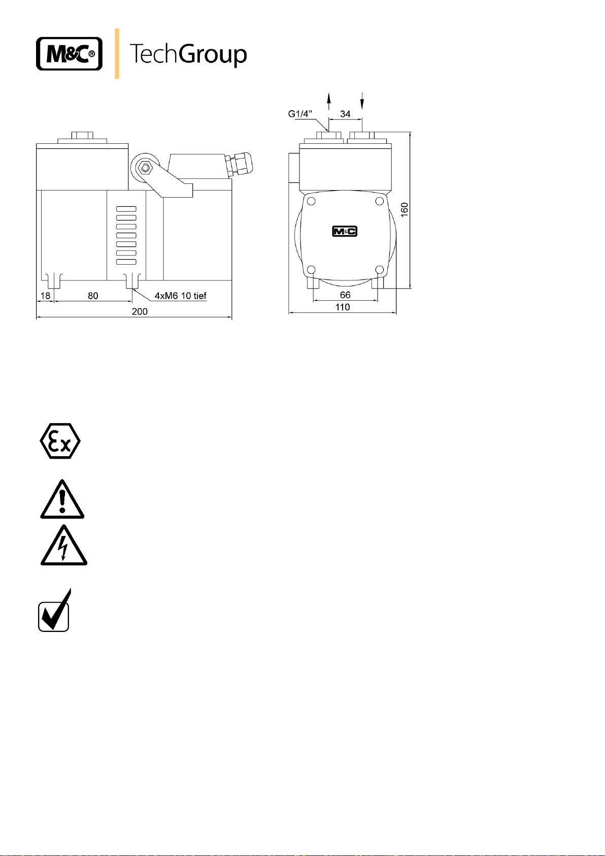
Figure 7 Dimensions (mm) pump MP47..
The diaphragm pumps type MP47, MP47/R, MP47-Z, MP47-Z/R,
MP47/D must not be used in hazardous areas.
WA R NI N G!
When connecting the equipment, please ensure that the supply
voltage is identical with the information provided on the model
type plate. The supply voltage is only allowed to deviate max. +6
% respectively -10 % from the indication on the model type plate.
NOTE!
Attention must be paid to the requirements of IEC 364 (DIN VDE
0100) when setting high-power electrical units with nominal voltages of up to 1000 V, together with the associated standards and
stipulations. Check the details on the type plate to ensure that the
equipment is connected up to the correct mains voltage. A main
switch and matching fuse must be provided externally (EN 60335-
1)! The main circuit of the pump type MP47 ... (230 V) must be
equipped with a protective motor switch 0,63 - 1 A corresponding
to the nominal current (over current protection) (EN 60335-1);
The main circuit of the pump type MP47 ... (115 V) must be
equipped with a protective motor switch 1 - 1,6 A corresponding
to the nominal current (over current protection) (EN 60335-1);
14.2 ELECTRICAL
14
When making the electrical installation the safety regulations must be observed. In particular make
sure that the electricity supply is isolated before trying to connect the pump.
The earthwire (ground) must be connected to the motor.
Gas sampling and gas conditioning technology 6-1.1.1-ME
Page 15

15
NOTE!
The pump must only be used in the conditions specified in the technical
data. The pump should be installed away from heat sources and freely ventilated to prevent any accumulation of heat. For outdoor installation, the pump
must be installed in a housing protected from frost in the winter and suffi-
ciently ventilated in summer. Exposure to direct sunlight must be avoided.
The pump must be installed so that contact with live parts (connections, possibly windings) is
impossible.
Figure 8 Electrical connection of the pump
Unscrew the cover of the connection box with the PG cable glands;
Put the cable through the cable gland and connect it according to figure 8; Connections are
marked in the connection box.
14.3 PNEUMATIC
Remove the protection plugs from the port threads (thread size G1/4”).
Accessories like hose connections are screwed into the port threads by sealing tape (using
M&C connectors sealing tape is not necessary).
Connect the suction and pressure lines.
Arrange the suction and pressure lines so that condensate cannot run into the pump.
Gas sampling and gas conditioning technology 6-1.1.1-ME
Page 16

16
NOTE!
The valve body must be fixed while mounting the fittings because moving
may change the pump capacity. Do not confuse hose-/tube connections for
sample gas inlet and outlet; the connections are labeled accordingly! Check
for tightness of all sample lines after connection! The tightness of the connections can only be guaranteed if the end section of the connection
hose/tube is flat (use a hose-cutter)!
15 SUPPLY LINE CONNECTIONS
15.1 HOSE-/TUBE CONNECTIONS
The gas inlet and outlet hoses/tubes are connected on the top of the pump. Standard G1/4" threaded
joints are available for the connection of the gas sample lines.
When connecting the sample gas supply hoses or tubes to the corresponding threaded connections,
pay attention to the following points:
Loosen the sleeve nut of the clamping-ring threaded joint by turning to the left. Take care that
the nut is removed carefully from the body of the threaded joint to avoid losing the clamping
ring which is mounted loose in the nut.
Push the sleeve nut over the connection hose/tube.
Push the clamping ring onto the connection hose/tube with the thicker bulge pointing to nut.
Push the hose/tube onto the supporting nipple in the threaded joint.
Tighten the sleeve nut by hand. The hose/tube is now mounted in such a way that it cannot
slip and is resistant to pressure.
The appropriate tube or hose threaded joint connections are available optionally from M&C.
16 START UP
Specific safety instructions for media being handled must be observed. Before pumping a medium,
the compatibility of materials of pump head, diaphragm and valves with the medium must be checked
(for pump materials: see technical data). The following steps should be carried out before initial startup:
The pump must not start against pressure or vacuum. When it is switched on the pressure in
the suction and pressure lines must be atmospheric. This must be so even when the pump restarts after the power has been cut off for a short period.
The maximum permissible operating pressure (see technical date) must not be exceeded,
even when the flow is restricted.
To prevent the maximum permissible operating pressure being exceeded, restriction or control
of the air or gas flow should only be carried out in the suction line.
Gas sampling and gas conditioning technology 6-1.1.1-ME
Page 17

17
NOTE!
The area in which the pump is situated when not in use must be
kept free of frost at all times!
WA R NI N G!
Aggressive medium is possible.
Wear protective glasses and proper protective clothing during
disassembly, repair or cleaning!
WA R NI N G!
It is necessary to take the pump off the mains before any assembly,
maintenance or repair work is carried out!
WA R NI N G!
Aggressive medium is possible.
Wear protective glasses and proper protective clothing during
disassembly, repair or cleaning!
If restriction or control of the air or gas flow is made on the pressure side ensure that the
maximum permissible operating pressure is not exceeded.
When the pump is at a standstill the inlet and exhaust must be at normal atmospheric pres-
sure.
Diaphragm and valve plates are the only parts subject to wear. Wear is usually indicated by a
drastic reduction in the pneumatic performance. When replacing parts proceed as described in
section 18.
Ambient conditions: see technical data.
17 CLOSING DOWN
If the pump is putting out of action for a short time no particular measures need to be taken.
18 MAINTENANCE
Before the maintenance work is carried out, it is necessary that the specific safety procedures pertaining to the system and operational process are observed!
Diaphragm and valve plates are the only parts of the pump subject to wear. They are simple to
change.
Gas sampling and gas conditioning technology 6-1.1.1-ME
Page 18

18
NOTE!
Always change valve plates, diaphragm and sealing rings at the same time.
Valve, suction side
Valve, pressure side
Figure 9 Sectional drawing pump MP47
Parts and tools required:
Valve plates and structured diaphragm (see spare part list , chapter 20)
Change the diaphragm and valve plates in the following sequence:
18.1 EXCHANGE OF THE DIAPHRAGM
Mark the position between housing A , diaphragm B and pressure plate C ;
Loosen the 4 hexagon screws H and remove the pressure plate C and the diaphragm head B ;
Unscrew the diaphragm K by hand out of the tapping hole of the rod L (counterclockwise);
Gas sampling and gas conditioning technology 6-1.1.1-ME
Page 19

19
WA R NI N G!
Aggressive medium is possible.
Wear protective glasses and proper protective clothing during
disassembly, repair or cleaning!
Loosen the 4 screws M and remove the cover N ;
Screw the new diaphragm K into the rod L hand-tight;
Turn the flywheel P until the rod L is in a central position. Control that the bulge of the dia-
phragm K fits to the groove of housing A ;
Fix the diaphragm head B and the pressure plate C according to the mark;
Fix the 4 hexagon scews H constantly over cross until the plate springs R are flat;
Turn the flywheel P and check whether it works proper;
Mount the cover N ;
18.2 EXCHANGE OF THE VALVE PLATES
Loosen the 6 hexagon screws D and remove the pressure ring E ;
Change the o-ring S at the valve body F on the pressure side;
Change the valve plate T . Check whether the protection ring U is in the right position and the
6 layers of the valve plate T point to the top;
Screw in the valve bodies F and tighten them in a moderate way;
Change the o-ring S on the sucking side;
Remove the valve plate T and change it with a new one. Check whether the protection ring U
is in the right position and the 6 layers of the valve plate T point to the bottom;
Screw in the valve bodies G and tighten them in a moderate way;
Put on the pressure ring E and tighten the 6 hexagon screws.
18.3 CLEANING
When changing valve plates and diaphragm, inspect all parts for dirt before assembling the
pump head and clean them if necessary.
As far as possible clean the parts with a dry cloth. Solvents should not be used as they can
attack the plastics and synthetic rubber parts. If a compressed air line is available, blow the
parts out with it.
Gas sampling and gas conditioning technology 6-1.1.1-ME
Page 20

20
Problem/Indication
Possible cause
Check/Action
Pump produces no
flow
No main supply
Check power supply; Check plug for correct
fit
Connections or lines are
blocked
Remove blockade
An external valve is closed or
a filter is blocked
Open valve or clean dirty/blocked filter
Liquid (condensate) has collected in the pump head
Let the pump for a few minutes pumping air;
Flow, pressure or
vakuum too low
Diaphragm or valves are
weared out
Change diaphragm or/and valves
Compare the actual perfor
mance with the figures in
the technical data
The pump is not designed for this condition
There is pressure on the
pressure side and at the same
time vacuum or a pressure
above atmospheric on the
suction side
The pump is not designed for this condition
The cross-section of the
pneumatic lines or connected
components is too small, or
they are restricted
To measure the performance, disconnect the
pump from the system (smaller diameter
tubing or a valve can significantly affect
performance)
A leak at a connector, in a
diaphragm/valve plate is
damaged or pump heads
dirty
Insulate the leak, tighten the screws, clean
or exchange dirty parts
NOTE!
If the pump does not operate properly and you cannot find any of the above
mentioned faults, send it back to M&C.
If you have been handling dangerous or highly aggressive gases please
clean the pump before dispatch.
For recommended spare parts please see section 20.
19 TROUBLE SHOOTING
Before working on the pump isolate the power supply securely, then check that the lines are not live.
The following tips for fault-finding are best employed in the sequence shown.
Gas sampling and gas conditioning technology 6-1.1.1-ME
Page 21

21
Diaphragm pump MP47, MP47/R, MP47-Z,
MP47-Z/R, MP47/D
(C) Consumable parts (R) Recommended spare parts (S) Spare parts
Recommended quantity
being in operation [years]
Part No.
Description
C/R/S
1 2 3
90P1108
Ring type U for valve chamberr MP47
R - -
1
90P1105
Diaphragm type K for MP47 Material: FPM,
PTFE coated
R 1 2
3
90P1113
O-Ring 25 f. MP47/Z/R, Material: FPM
R 1 2
3
90P1110
Valve type T f. MP47, 1 pc.
Material: PTFE (required 2 pcs.)
R 2 4
6
90P1111
Valve body type F/G 1/4”i for MP47
Material: PTFE
R 1 2
3
90P1112
Valve type F/G 1/4”i for MP47/R, MP47-Z/R
Material: PTFE
R 1 2
3
90P3025
Connecting rod for MP47 Type L
S - -
1
90P3027
Pump head top part for MP47 Material: PTFE
S - -
1
90P3028
Pump head top part for MP47/R, MP47-Z/R
with boring for needle valve Material: PTFE
S - -
1
90P6000
Needle from PTFE with screw part out of PTFE
for needle valve MP47-Z-NV (until 9.93)
S - -
1
90P6005
Needle from PTFE
for needle valve MP47-Z-NV (until 9.93)
S - -
1
90P6010
Seal ring out of PTFE
for needle valve MP47-Z-NV (until 9.93)
S - -
1
90P6030
Needle valve for MP47/R, MP47-Z/R (from
10.93) seal ring and needle out of PTFE
S - -
1
90P6015
Needle out of PTFE for MP-Z/R (from 10.93)
S - -
1
90P6020
Seal ring out of PTFE
for needle valve MP47-Z/R (from 10.93)
S - -
1
20 SPARE PARTS LIST
Wear, tear and replacement part requirements depend on specific operating conditions.
The recommended quantities are based on experience and they are not binding.
Gas sampling and gas conditioning technology 6-1.1.1-ME
Page 22

90P6025
Adapter out of PTFE
for needle valve MP47-Z/R (from 10.93)
S - -
1
PVDF Male connectors with G-thread (ISO 1010031)
05V1045
Male connector DN 4/6-G1/8” Material: PVDF
S - -
2
05V1050
Male connector DN 6/8-G1/8” Material: PVDF
S - -
2
05V6600
Verrule DN 4/6, PVDF
S 2 2
4
05V6602
Verrule DN 6/8, PVDF
S 2 2
4
05V6605
Union nut DN 4/6, PVDF
S 2 2
4
05V6607
Union nut DN 6/8, PVDF
S 2 2
4
21 ANNEXE
22
Further product documentation can be seen and downloaded from our home page:
www.mc-techgroup.com
Gas sampling and gas conditioning technology 6-1.1.1-ME
 Loading...