

Page 1
Instruction Manual
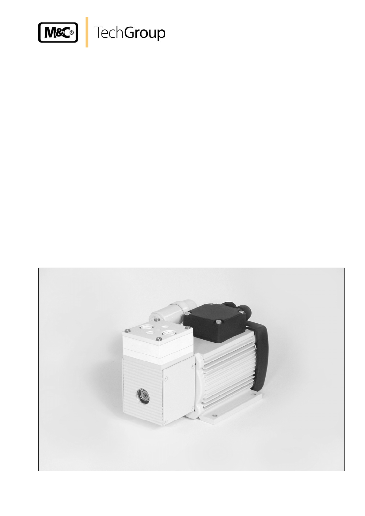
Diaphragm Pump Series MP
®
Version MP30
Gas sampling and gas conditioning technology 6-1.3.5-ME
Page 2

2
Dear customer,
we have made up this operating manual in such a way that all necessary information about the
product can be found and understood quickly and easily.
Should you still have any question, please do not hesitate to contact M&C directly or go through your
appointed dealer. Respective contact addresses are to be found in the annexe to this operating
manual.
Please also contact our homepage www.mc-techgroup.com
for further information about our
products. There, you can read or download the data sheets and operating manuals of all M&C
products as well as further information in German, English and French.
This Operating Manual does not claim completeness and may
be subject to technical modifications.
© 01/2003 M&C TechGroup Germany GmbH. Reproduction of this
document or its content is not allowed without permission from M&C.
2nd Edition: 03/2011
Gas sampling and gas conditioning technology 6-1.3.5-ME
Page 3

3
Content
1 General information ..................................................................................................................... 4
2 Declaration of conformity ........................................................................................................... 4
3 Safety instructions ....................................................................................................................... 5
4 Warranty ....................................................................................................................................... 5
5 Used terms and signal indications ............................................................................................. 6
6 Introduction .................................................................................................................................. 7
7 Applications ................................................................................................................................. 7
7.1 Ambient conditions ................................................................................................................. 8
7.2 Safety ..................................................................................................................................... 8
8 Technical data .............................................................................................................................. 9
9 Dimensions ................................................................................................................................ 10
10 Receipt and storage................................................................................................................... 10
11 Installation information ............................................................................................................. 10
11.1 Mechanical ........................................................................................................................... 11
11.2 Electrical ............................................................................................................................... 11
11.3 Pneumatic ............................................................................................................................ 12
12 Commissioning .......................................................................................................................... 13
13 Decommissioning ...................................................................................................................... 14
14 Maintenance ............................................................................................................................... 14
14.1 Replacing diaphragms, valve plates and sealing rings ........................................................ 15
Cleaning ...................................................................................................................................... 16
15
16 Troubleshooting......................................................................................................................... 17
17 Spare parts ................................................................................................................................. 18
18 Appendix .................................................................................................................................... 18
List of illustrations
Figure 1 Delivery capacity MP30 .................................................................................................... 7
Figure 2 Dimensions (mm) MP30 ................................................................................................. 10
Figure 3 Section drawing of pump head MP30 ............................................................................ 15
Gas sampling and gas conditioning technology 6-1.3.5-ME
Page 4

4
Head Office
M&C TechGroup Germany GmbH Rehhecke 79 40885 Ratingen Germany
Telephone: 02102 / 935 - 0
Fax: 02102 / 935 - 111
E - mail: info@mc-techgroup.com
www.mc-techgroup.com
1 GENERAL INFORMATION
The product described in this operating manual has been examined before delivery and left our works
in perfect condition related to safety regulations. In order to keep this condition and to guarantee a
safe operation, it is important to heed the notes and prescriptions made in this operating manual.
Furthermore, attention must be paid to appropriate transportation, correct storage, as well as
professional installation and maintenance work.
All necessary information a skilled staff will need for appropriate use of this product are given in this
operating manual.
2 DECLARATION OF CONFORMITY
CE - Certification
The product described in this operating manual complies with the following EC directives:
EMV-Instruction
The requirements of the EC directive 2004/108/EC “Electromagnetic compatibility“ are met.
Low Voltage Directive
The requirement of the EC directive 2006/95/EC “Low Voltage Directive“ are met.
The compliance with this EC directive has been examined according to DIN EN 61010.
Declaration of conformity
The EU Declaration of conformity can be downloaded from the M&C homepage or directly requested
from M&C.
Gas sampling and gas conditioning technology 6-1.3.5-ME
Page 5

5
3 SAFETY INSTRUCTIONS
Please take care of the following basic safety procedures when mounting, starting up or
operating this equipment:
Read this operating manual before starting up and use of the equipment. The information and
warnings given in this operating manual must be heeded.
Any work on electrical equipment is only to be carried out by trained specialists as per the regulations
currently in force.
Attention must be paid to the requirements of VDE 0100 (IEC 364) when setting high-power electrical
units with nominal voltages of up to 1000 V, together with the associated standards and stipulations.
Check the details on the type plate to ensure that the equipment is connected to the correct mains
voltage.
Protection against touching dangerously high electrical voltages:
Before opening the equipment, it must be switched off and hold no voltages. This also applies to any
external control circuits that are connected.
The device is only to be used within the permitted range of temperatures and pressures.
Check that the location is weather-protected. It should not be subject to either direct rain or moisture.
The pump must not
be used in hazardous areas.
Installation, maintenance, monitoring and any repairs may only be done by authorized personnel with
respect to the relevant stipulations.
4 WARRANTY
If the equipment fails, please contact M&C directly or else go through your M&C authorised dealer.
We offer a one year warranty as of the day of delivery as per our normal terms and conditions of sale,
and assuming technically correct operation of the unit. Consumables are hereby excluded. The terms
of the warranty cover repair at the factory at no cost or the replacement at no cost of the equipment
free ex user location. Reshipments must be send in a sufficient and proper protective packaging.
Gas sampling and gas conditioning technology 6-1.3.5-ME
Page 6

6
5 USED TERMS AND SIGNAL INDICATIONS
This means that death, severe physical injuries and/or important
material damages will occur in case the respective safety measures
DANGER!
WARNING!
CARE!
CARE!
ATTENTION!
NOTE!
SKILLED STAFF
are not fulfilled.
This means that death, severe physical injuries and/or important
material damages may occur in case the respective safety
measures are not fulfilled.
This means that minor physical injuries may occur in case the
respective safety measures are not fulfilled.
Without the warning triangle means that a material damage may
occur in case the respective safety measures are not met.
This means that an unintentional situation or an unintentional status
may occur in case the respective note is not respected.
These are important information about the product or parts of the
operating manual which require user’s attention.
These are persons with necessary qualification who are familiar with
installation, use and maintenance of the product.
Gas sampling and gas conditioning technology 6-1.3.5-ME
Page 7

7
6 INTRODUCTION
The MP30 diaphragm pump is suitable for 100% oil-free transport of corrosive gases. It has been
dimensioned and designed specifically for use in the analytical sector. The pump is gas-tight and
maintenance-free.
7 APPLICATIONS
The transported gas remains analytically pure due to the absolutely lubricant-free operating pump. A
special diaphragm and valve system ensures freedom from maintenance and a long useful life.
The pump is available for 230V or 115V mains voltage as well as with motor in an explosion-proof
design. The MP30 has a delivery capacity of 7.5l/min at atmospheric pressure. The output on the
pressure side is limited to maximum 2.5 bar absolute..
Application examples are:
Transport of gases and vapours with a temperature of +5°C... + 40°C
Maximum allowable working pressure, final vacuum and delivery capacity according to technical
data
Prior to use in unknown pumping media, the compatibility of the materials of the pump head,
diaphragm and valves with the medium must be verified.
500
450
400
350
300
250
[Nl/hr]
200
150
100
50
0
0 0,25 0,5 0,75 1 1,25 1,5 1,75 2 2,25 2,5
[bar abs.]
Figure 1 Delivery capacity MP30
Diaphragm pumps of the MP30 type series are not suitable for transporting
liquids.
NOTE!
[Nl/hr]
[Nl/hr] with constant
sucction pressure -0,2bar
Gas sampling and gas conditioning technology 6-1.3.5-ME
Page 8

8
7.1 AMBIENT CONDITIONS
The following ambient conditions must be maintained during operation:
Ambient temperature range in operation: +5°C .... + 40°C.
The pumps must be protected from water and dust.
Sufficient ventilation must be provided during operation.
The pump type MP30 must not be used in areas subject to explosion hazards or for transporting a
potentially explosive medium. The pumps have the degree of protection IP54 as standard.
7.2 SAFETY
The following must be observed concerning safety when using MP30 diaphragm pumps:
The pump must only be used for the intended purpose (see 7.).
The pumps must not be used in areas subject to explosion hazards
or for transporting a potentially explosive medium.
When transporting toxic media, system-specific and safety-relevant
regulations must be observed (MAC values).
The transported medium must be safely discharged.
When connecting other components to the pump, the pneumatic
conditions must be observed (see 8.).
WARNING!
When connecting the pump top the electrical system, the relevant
safety requirements must be observed.
The standard internal thermal safety cut-out protects the pump
against overload. The pump automatically restarts after cooling
down. Hazardous situations constituted by this must be prevented
by suitable measures.
The compatibility of the pump materials with the medium to be
transported must be verified prior to use of the pump and the
safety requirements for the media to be used observed.
Gas sampling and gas conditioning technology 6-1.3.5-ME
Page 9

9
8 TECHNICAL DATA
Diaphragm pump MP30 /230V MP30 /115V
Part No.
Voltage supply 230V 50Hz
Power input 70W
Power consumption 0,45A 0,7A
Degree of protection IP 54 - DIN 40050
Delivery capacity max.
Operating pressure 0.14 to max. 2.5 bar abs.
Gas temperature +5°C to +40°C
Ambient temperature +5°C to +40°C
Storage temperature -15°C to +60°C
Gas connections G1/8" i DIN ISO 228/1
Electrical equipment
standard
Medium contacted parts
Pump head
Diaphragms
Valves
Weight 3,1kg 3,3kg
Material designations according to ISO 1629 and 1043.1
* Litre in standard condition
02 P 1500 02 P 1500a
115V 60Hz
10%
10%
7.5 l/min*
EN 61010, part 1
PVDF, SS316Ti
CR, PTFE coated
FFPM
Gas sampling and gas conditioning technology 6-1.3.5-ME
Page 10

10
9 DIMENSIONS
The dimensions of the MP30 are shown below:
Figure 2 Dimensions (mm) MP30
10 RECEIPT AND STORAGE
Carefully remove the diaphragm pump and any accessories from the transport packaging
immediately upon receipt and check the delivery against the delivery note.
Check the contents for possible transport damage and immediately notify the transport insurer of
any damage.
The diaphragm pump should be stored in a protected, frost-free room.
NOTE!
11 INSTALLATION INFORMATION
The safety rules and regulations for the prevention of accidents must be observed during installation
and also subsequent operation. The information in Chapter 3‚ “Safety” must be observed.
Gas sampling and gas conditioning technology 6-1.3.5-ME
Page 11

The safety requirements applicable to the respective media to be
transported must be observed.
In order to prevent a disturbing accumulation of heat, the pumps
should be installed away from sources of heat and freely ventilated.
NOTE!
For installation outdoors, the pump must be installed in a
protective housing frost-free in winter and sufficiently ventilated in
summer. Direct exposure to sunlight must be avoided.
Pumps have mechanical moving parts that can induce vibrations.
To prevent damages at the pump or at peripheral components /
facilities as well as minimizing noise development an appropriate
NOTE!
vibration decoupling is necessary. For this M&C can deliver e.g.
anti-vibration pads.
This explicit is also valid for the connection of the sample lines at
the pump head.
11.1 MECHANICAL
11
The fixing dimensions are shown in Figures 2 and 3.
The pumps must be installed in such a way that the impeller is able to draw in sufficient cooling air.
The pumps should be installed at the highest point in the system and/or with the pump head
pointing downward to prevent an accumulation of condensate – this will extend the useful life of the
pump.
11.2 ELECTRICAL
Electrical installation must take place in compliance with the safety regulations. Before connecting the
pump, safe isolation from the supply must be ensured.
The protective conductor must be connected to the pump motor.
A device for disconnecting the pump from the electrical system must be provided in the electrical
installation (according to EN 60335-1).
The supply circuit should be provided with a fuse with a rating corresponding to the current
consumption (over-current protection, current consumption, see technical data).
The supply voltage must be compared with the voltage shown on
WARNING!
the rating plate. A voltage deviation of about 10% is admissible.
The pumps must be mounted so that contact with live parts (e.g.
electrical connection, possibly motor windings) is excluded.
Gas sampling and gas conditioning technology 6-1.3.5-ME
Page 12

11.3 PNEUMATIC
12
Components to be connected to the pump must conform to the pneumatic
data of the pump.
NOTE!
Remove safety stoppers from threaded gas connections (thread size G1/8”).
Accessories such as threaded hose couplings must be screwed into the threaded connection with
sealing tape (the use of sealing tape is unnecessary when using M&C couplings).
Connect suction and pressure pipe.
Do not interchange hose connections for sample gas inlet and outlet; the
connections are appropriately marked.
NOTE!
After connecting all pipes, they must be checked for tightness.
When connecting the hoses to optional threaded hose couplings, the following should be noted:
The tightness of the connection can only be ensured when the connecting
NOTE!
hose has a straight terminating edge (use of a hose cutter).
Loosen the swivel nut of the clamping ring by turning anticlockwise; it must be ensured that the nut
is carefully removed from the coupling, so that the clamping ring lying loosely in the clamping ring is
not lost.
Slide the swivel nut on to the connecting hose.
Slide the clamping ring with the thicker part pointing towards the nut on to the connecting hose.
Fit the hose on to the supporting nipple in the coupling;
Tighten the swivel nut hand-tight.
The hose is not connected non-slip and pressure-proof.
Optional threaded couplings for DN 4/6 or DN 6/8 can be obtained through M&C
Route the suction and pressure pipe so that no condensate can flow into the pump.
Gas sampling and gas conditioning technology 6-1.3.5-ME
Page 13

13
12 COMMISSIONING
Prior to commissioning, system and process-specific safety measures must be observed.
For the media to be transported, the respective safety requirements and measures must be taken into
account.
Prior to using a medium, the compatibility of the materials of the pump head, diaphragm and valves
with the medium must be verified (for materials, see technical data).
The following steps must be carried out for commissioning:
The pumps must not start against pressure or vacuum. When the pump is switched on, the normal
atmospheric pressure must prevail in the pipes. This applies similarly during operation following a
brief interruption of power.
The maximum allowable working pressure (see technical data) must not be exceeded.
Restriction or regulation of the gas flow should only take place in the suction-sided pipe in order to
avoid exceeding the maximum allowable working pressure.
If restriction or regulation of the gas flow takes place on the pressure side, it must be ensured that
the maximum allowable working pressure of the pump is not exceeded.
With the pump stationary, normal atmospheric pressure must be established in the pipes.
Diaphragms and valve plates are the only wearing parts of the pumps. Wear is usually noticeable
by a considerable reduction in pneumatic power. Replacement must take place as described in
chapter 14ff.
Ambient conditions, see technical data.
For pumps used as vacuum pump and compressor:
Pressure and vacuum cannot be produced simultaneously.
The pumps must not be used in areas subject to explosion hazards
or for transporting a potentially explosive medium.
The transported medium must be safely discharged.
When connecting other components to the pump, the pneumatic
conditions must be observed (see 6.).
When connecting the pump to the electrical system, the relevant
safety requirements must be observed.
WARNING!
The standard internal thermal safety cut-out protects the pump
against overload. The pump automatically restarts after cooling
down. Hazardous situations constituted by this must be prevented
by suitable measures.
For the transport of aggressive or toxic media, the system-specific
safety requirements must be observed. Purging with air or inert gas
under atmospheric conditions is recommended prior to
decommissioning.
Gas sampling and gas conditioning technology 6-1.3.5-ME
Page 14

13 DECOMMISSIONING
14
The site of installation of the diaphragm pump must remain frost-
NOTE!
free also during the time when the unit is switched off.
No further particular measures are required for decommissioning.
When transporting aggressive media, purging the pump with inert
gas under atmospheric conditions is recommended prior to
WARNING!
decommissioning. If there is no risk of explosion, air can also be
used for this purpose.
Aggressive media residues possible. For disassembly, repair or
cleaning of the pump, safety goggles and suitable protective
clothing must be worn!
14 MAINTENANCE
Before carrying out maintenance work, the system and process-specific safety measures must be
observed!
WARNING
Dangerous voltage. Before working on the diaphragm pump, the
same must be safely isolated from the supply and disconnection
from the supply verified
!
Aggressive or toxic media residues possible. For disassembly,
repair or cleaning of the pump, safety goggles and suitable
protective clothing must be worn. Wearing parts must be disposed
of in a proper manner!
Diaphragms and valve plates are the only wearing parts of the pumps and can be easily replaced.
It is recommended to replace valve plates, diaphragms and sealing
NOTE!
rings simultaneously to maintain the life expectancy of the pump.
For the maintenance or repair of the pump, the following tools are parts are required:
2 valve plates, 2 sealing rings and 1 diaphragm according to spare parts list.
Cross-tip screwdriver No.2.
Cross-tip screwdriver No.1.
Felt-tip pen.
Gas sampling and gas conditioning technology 6-1.3.5-ME
Page 15

15
14.1 REPLACING DIAPHRAGMS, VALVE PLATES AND SEALING RINGS
Figure 4 shows a sectional drawing of the pump head.
6
15
4
3
10
5
2
1
9
11
7
8
5
4
1
14
Positioning
the cup
spring 11
15
6
1 Intermediate plate
2 Valve plate
3 Sealing ring
4 Head cover
5 Screw
6 Screw cap
7 Screw
8 Diaphragm
9 Supporting cup
10 Adjusting washers
11 Cup spring
12 Impeller
13 Impeller cover
14 Housing
15 Pressure plate
M Mark
12
13
M
Figure 3 Section drawing of pump head MP30
Replacing the diaphragm:
Mark position of pressure plate 15, head cover 4, intermediate plate 1 and housing 14 by making a
continuous line with a felt-tip pen.
Loosen four head screws 5.
Remove pressure plate 15, head cover 4 and intermediate plate 1 from pump housing.
Loosen four fixing screws in impeller cover 13 and remove.
Bring diaphragm 8 into top position by turning impeller 12;
Unscrew diaphragm on side edges anticlockwise.
Gas sampling and gas conditioning technology 6-1.3.5-ME
Page 16

16
Remove support cup 9, adjusting washers 10 and cup spring 11 from thread bolt of diaphragm and
clean if necessary.
Fitting the new diaphragm takes place in reverse order.
The edge of the cup spring must point towards the diaphragm.
NOTE!
Replacing valve plates and sealing rings:
Loosen screws 7 and separate head cover 4 from intermediate plate 1.
Remove valve plates 2 and sealing rings 3 from intermediate plate.
Inspect valve seat, intermediate plate or ribbed cover for cleanliness and damage and replace if
necessary.
Fit new valve plates 2 (suction and pressure side or top and bottom side are identical); check for
correct position by lightly moving the valve seat.
Fit sealing rings 3 in intermediate plate 1.
Join head cover 4 and intermediate plate 1 together (felt-tip pen mark must be in alignment) and
check centred seat through lateral movement.
Fix head cover 4 and intermediate plate 1 in place with screws 7.
Fitting pump head:
Place intermediate plate 1 and head cover 4 according to felt-tip pen mark M on pump housing.
Also place pressure plate 15 in position (mark) and lightly tighten crosswise with screws 5 and cup
springs.
Check pump for smooth operation by turning impeller 12.
Tighten screws 5 crosswise until cup springs rest flat against pressure plate.
15 CLEANING
When replacing the valve plates and diaphragms, all parts must be checked for fouling before
assembling the valve head and cleaned if necessary. If available, the parts should carefully be blown
out with compressed air.
Gas sampling and gas conditioning technology 6-1.3.5-ME
Page 17

17
16 TROUBLESHOOTING
Before carrying out any work on the pump, it must be safely isolated from the supply and
disconnection from the supply verified. The following instructions for troubleshooting are hierarchically
structured, i.e. to be used in the specified order.
Problem/Indication Possible cause Check/Remedy
Pump does not
transport
Connections or pipes are
An external valve is closed
Liquid (condensate) has
Delivery capacity,
pressure or vacuum
too low
Problem/Indication Possible cause Check/Remedy
Initially compare reached
Liquid (condensate) has
Excess pressure is present
Pneumatic lines or
Leaks at connections, pipes
No system voltage available. Check system voltage. Check mains cable for
tightness.
Clear blockage.
blocked.
Open valve or clean fouled/clogged filter.
or a filter is clogged.
Purge pump with inert gas for several minutes.
collected in the pump head.
If there is no risk of explosion, air can also be
used for this purpose. Install pump at the
highest point in the system.
MP30:
Thermal safety cut-out has
Disconnect pump from the supply, allow to cool
down and remedy cause of overheating.
operated due to overheating.
Diaphragms or valve plates
Replace worn parts (see 14. ff).
worn.
Pump is not designed for this condition.
pump capacity with technical
data in chapter 1.2 or data
sheet.
Purge pump with inert gas for several minutes.
collected in the pump head.
If there is no risk of explosion, air can also be
used for this purpose. Install pump at the
highest point in the system.
Pump is not designed for this condition.
on the pressure side and on
the suction side
simultaneously a vacuum or
pressure above atmospheric
pressure.
To measure capacity values, decouple pump
connecting parts have an
insufficient cross-section or
are restricted.
from the system; a pipe with insufficient cross-
section or, e.g. a valve installed in the system
can alter the measured value considerably.
Steam leaks.
or pump head.
Diaphragms or valve plates
are faulty or head parts are
Tighten screwed connections.
Replace faulty parts.
Clean fouled parts or replace.
fouled.
Gas sampling and gas conditioning technology 6-1.3.5-ME
Page 18

18
®
If none of the specified faults can be located, despite the pump not
operating correctly, the pump should be returned to M&C for examination.
NOTE!
When sending diaphragm pumps for repair to M&C Customer Service,
information about the transported medium is required.
Our workshop should be informed in particular about aggressive media.
Where pumps have been used for transporting dangerous or highly
aggressive gases, these should be cleaned prior to being returned.
17 SPARE PARTS
Wear, tear and replacement part requirements depend on specific operating conditions.
The recommended quantities are based on experience and are not binding.
Diaphragm Pump
Type MP30
(C) consumable parts, (S) spare parts
V/E/T 1 2 3
90P1500
90P1510
90P1505
Diaphragm 8
Set sealing ring 3 (2 pc., Kalrez
Set valve plate 2 (2 pc.)
)
C 1 2 3
C 1 2 3
C 2 4 6
PVDF male connectors with G-thread (ISO 1010031)
05V1045 Straight connector
S - - 2
DN 4/6-G1/8” material: PVDF
05V1050 Straight connector
S - - 2
DN 6/8-G1/8” material: PVDF
05V6600 Ferrule DN 4/6 PVDF S 2 2 4
05V6602 Ferrule DN 6/8 PVDF S 2 2 4
05V6605 Union nut DN 4/6 PVDF S 2 2 4
05V6607 Union nut DN 6/8 PVDF S 2 2 4
18 APPENDIX
Recommended quantity
MP30 being in operation
(f.d. = for demand)
More product documentation is available on our Internet catalogue:
www.mc-techgroup.com
Gas sampling and gas conditioning technology 6-1.3.5-ME
 Loading...