

Page 1
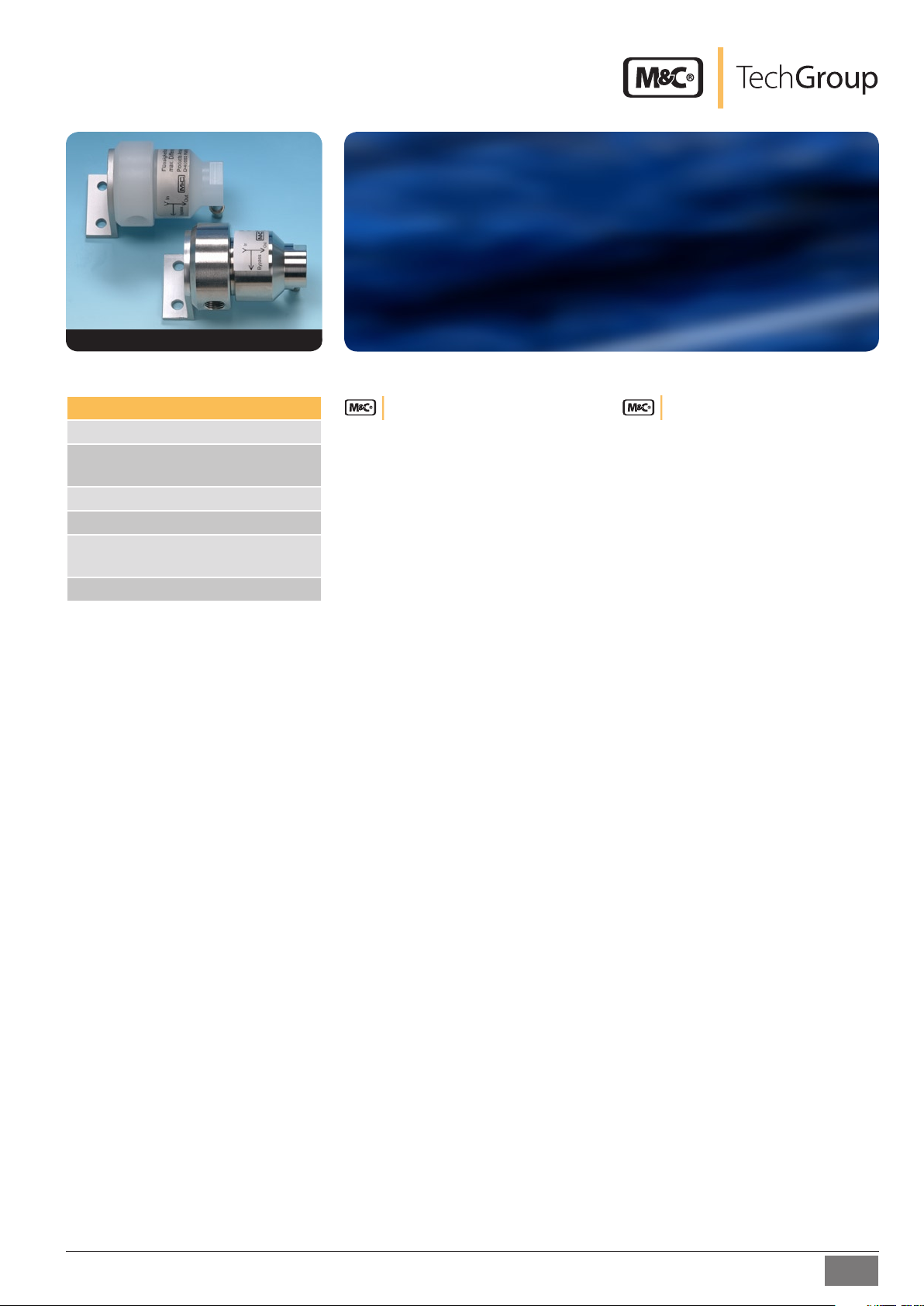
Liquid stop LB-1PV and LB-1SS
for protecting gas analysers and gas-phase
chromatographs against liquids
LB-1PV, LB-1SS
Special Features
Sure protection against liquid inrush
Reliable removal of liquid coming
through
Also suitable for high pressures
Available in stainless steel and PVDF
Easy change of the hydrophobic
protective membrane
With wall mounting holder
Application
The M&C liquid-stop LB-1.. is suitable for
protecting analysers against inrush of liquids
out of the gas conditioning unit which is
mounted before the analyser. This avoids
major damages of the analyser.
The most useful position of the liquid stop
LB-1.. is behind the gas conditioning unit,
directly before the flowmeter of the analyser.
5-1.10.9
Description
The hydrophobic protective membrane of
the liquid-stop LB-1.. is placed between the
two parts of the housing which are screwed
together. It is lined with a porous glass filter
frit in order to secure stable proportions.
The pore sizes of the protective membrane
are designed in such a way that gas molecules and steam can pass through but liquid
molecules are retained.
The gas inlet and outlet are positioned in
an horizontal line inside the housing. The
liquid outlet shows downwards when being
mounted.
Due to the horizontal flow direction of the
gases and because possible liquids are draining off on the protective membrane due to
its gravity, the leaking through of liquids to
the analyser is avoided.
Eventually occuring liquid can be let off via
a peristaltic pump SR25.1, separator and
automatic liquid drain ADS-SS or a condensate vessel TG1 (dip tank). The LB-1 has got a
respective connection possibility.
Changing the membrane is easy to handle.
The optimum positioning of the sealing
O-rings guarantees always a sure sealing of
both housing parts.
The filter inlet and outlet can be turned by
180° on the wall mounting holder so that a
flexible adaption to local circumstances is
possible during mountage.
10.03/11.06
M&C | TechGroup Germany GmbH
Rehhecke 79, D-40885 Ratingen
info@mc-techgroup.com
www.mc-techgroup.com
Fon +49 (0)2102 935-0
Fax +49 (0)2102 935-111
1
Page 2
2
5-1.10.9
M&C | TechGroup Germany GmbH
Rehhecke 79, D-40885 Ratingen
info@mc-techgroup.com
www.mc-techgroup.com
Fon +49 (0)2102 935-0
Fax +49 (0)2102 935-111
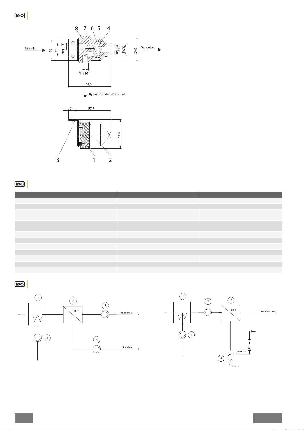
Dimensions
Dimensions in mm
1 Upper part of housing
2 Lower part of housing
3 Holding angle
4 Glass filter frit
5 Hydrophobic protective membrane
6 Flat ring of Teflon
7 O-ring FPM
8 O-ring FPM
Technical Data
Liquid-stop LB-1PV LB-1SS
Part No. 03F4005 03F4000
Gas flow max. 200 Nl/h
Gas pressure 0,3-2 bar abs.
∆P max. 0,5 bar
Differential pressure with clean
protection membrane, medium air, 20°C
Temperature sample gas max. +80 °C max. +100 °C
Ambient temperature 0 °C to +60 °C
Storage temperature -25 °C to +80 °C
Stagnant space 4 ml
Material of gas bearing parts PVDF, FPM, PTFE, Polyester, glass 1.4571, FPM, PTFE, Polyester, glass
Sample gas / drain connections NPT 1/8"i DIN ISO 228/1
Mounting / weight wall mounting / approx. 0,3 kg
50 100 mbar
100 200 Nl/hr
0,3 -10 bar abs.
∆P max. 0,5 bar
Examples for application
1 Gas cooler
2 Liquid-stop LB-1
4 Liquid drain with peristaltic pump SR25.1
5 Gas sample pump
6 Seperator and automatic liquid drain ADS-SS
Page 3

Upper part of housing
Lower part of housing
O-ring FPM
Glass filter frit
Flat-ring PTFE
Hydrophobic
protective membrane
Glass fibre surface
to be layed onto
glass filter frit
Attention: Do not touch on
the protective membrane!
O-Ring
Smooth side
Mounting bracket
Part No.:90F4010
Part No.:90F4005
Part No.:90F3515
Part No.:90F3510
Part No.:90F4000
Part No.:90F3520
Part No.:90F3525
Part No.:90F4020
Connection of the gas sample line
The connections (3 x 1/8”NPT i) for the gas sample lines are marked on the type plate and in the above drawing. They are executed with
respective screw fittings (see also data sheet 7-1.1) which are screwed gastight into the LB-1 with the aid of PTFE tape.
Changing the protection membrane
In case the hydrophobic protection membrane is dirty or overflowed so that the required flowrate is too short, it is advisable to exchange the
protective membrane incl. glass frit, PTFE flat ring and Viton O-ring (set I of spare parts, Part-No. 90F3530).
In case of interruption of the flow, the system has to be checked immediately!
During mountage attention must be paid to absolute cleanliness because impurities may impair the function of the LB-1!
By touching the surface with your hand, the protection membrane will be destroyed!
Aggressive condensate possible. Wear safety glasses and protective clothes!
For changing the protective membrane, unscrew the lower part of the liquid stop with the aid of an open-jawed spanner SW17. After this,
take out the O-rings and the glass frit, clean the housing parts and remount the LB-1 as shown below.
For a perfect function it is necessary that the protective membrane is positioned with its surface with fibre glass structure
onto the flat side of the glass frit! When changing the O-ring on the upper part of the LB-1 (Part-No. 90F4020), it is important
to draw up and not to roll up the O-ring. This way, a twisting and a respective leakage are avoided.
Part No. Description
90F4020 FPM O-ring for upper part LB-1
90F3515 FPM O-ring for CLF-5, CG-2 und LB-1
90F3525 PTFE flat ring for CLF-5 and LB-1
90F3510 Hydrophobic protective membrane for CLF-5 and LB-1
90F3520 Glass filter frit for CLF-5 and LB-1
90F4030 Spare part set LB-1 consisting of glass filter frit, protective membrane, flat ring PTFE, O-rings FPM
Recommended spare parts
Spare part set I Part No. 90F4030
including:
Protective membrane Part No. 90F3510
Glass filter frit Part No. 90F3520
Flat-ring PTFE Part No. 90F3525
O-ring FPM Part No. 90F3515
O-ring FPM Part No. 90F4020
5-1.10.9
M&C | TechGroup Germany GmbH
Rehhecke 79, D-40885 Ratingen
info@mc-techgroup.com
www.mc-techgroup.com
Fon +49 (0)2102 935-0
Fax +49 (0)2102 935-111
3
 Loading...