

Page 1
LA 1S
Embracing Challenge
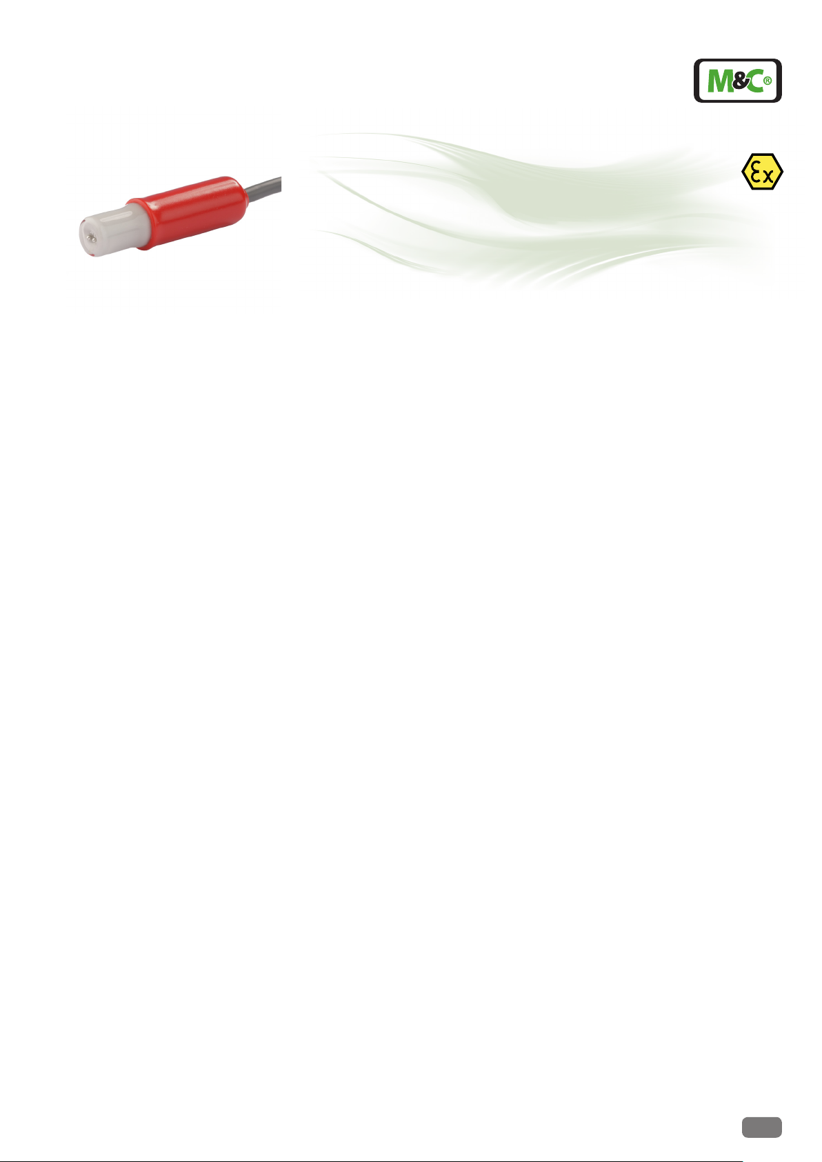
Liquid alarm sensors series LA®
for conductive media
Version LA 1S, LA 25S and ow chambers LS, LS 25 as well as
LA 1 and LA 25 for use in hazardous aereas
Special Features
Sure detection even of minimal liquid
quantities
line break monitoring for LA 1S and LA
25S
Integrable in M&C-Universal lters and
ow chambers
Also versions for higher pressure and
temperatures
No electrolytic eects on the sensor
surface
High chemical resistance
Cable length up to 100 meters
Application
Liquid alarm sensors are used in gas sample conditioning systems for monitoring gas
cooling and condensate drain-off devices in
order to provide protection for downstream
analysis instruments. This simple monitoring
device reliably signals the penetration of condensate in the event of cooling or condensate
drain-off equipment being defective and thus
avoids expensive down times as well as high
repair costs for analysis instruments.
In the event of alarm, the power for the
sample gas pump or a solenoid valve is to be
switched off in the gas sample conditioning
system.
Description
The M&C liquid sensors LA..S works on the
principle of electrical conductivity from 50
µS/cm conductance. In order to avoid electrolytic effects on the sensor surface, the sensors
are powered with alternating current.
The required electronic controller LA-1.. is
available in various versions and is described
in the separate data sheet 5-5.1.2.
Only the newly developed electronic controllers as described in the afore mentioned
data sheet from date of construction 04/2006
onwards can be used for the M&C liquid sensors LA..S.
The M&C LA..S liquid sensors are constructed
in such a way that any droplets of liquid in the
sample gas are attracted under gravity to the
sensor surface and even the smallest liquid
droplets trigger a sure and rapid alarm.
The LA 1S sensor is defined for operating
pressure up to 4 bar and LA 25S for up to 25
bar. The sensor protection corresponds to
type IP65 EN 60529.
The LA 1S sensor with its 12 mm diameter
glass body is mounted in the GL connection
of a F..-..-D universal filter or in the LS flow
chamber.
The LA 25S sensor has got a 1/4» special male connector for mounting in the
FSS..-D universal filter or for mounting in
8 mm tubes using a special union tee connector LS 25.
When mounting the universal filters and the
flow chamber, the gas inlet and gas outlets
can be rotated through 180° during assembly.
For hazardous areas the sensors LA 1 and LA
25 of the former series without line break
monitoring can be used because they are
«simple components». However the sensors
than may only be used with certified control
electronics, e.g. ER142 Exi (part no. 03E2009
for 230V or 03E2009a for 115V) for intrinsically
safe supply of the sensors.
Technical specications and illustrations are without
obligation, subject to modications. 09.96/11.06
M&C TechGroup Germany GmbH • Rehhecke 79 • 40885 Ratingen • Germany
info@mc-techgroup.com • www.mc-techgroup.com • Fon +49 2102 935-0 • Fax +49 2102 935-111
8.1
Page 2
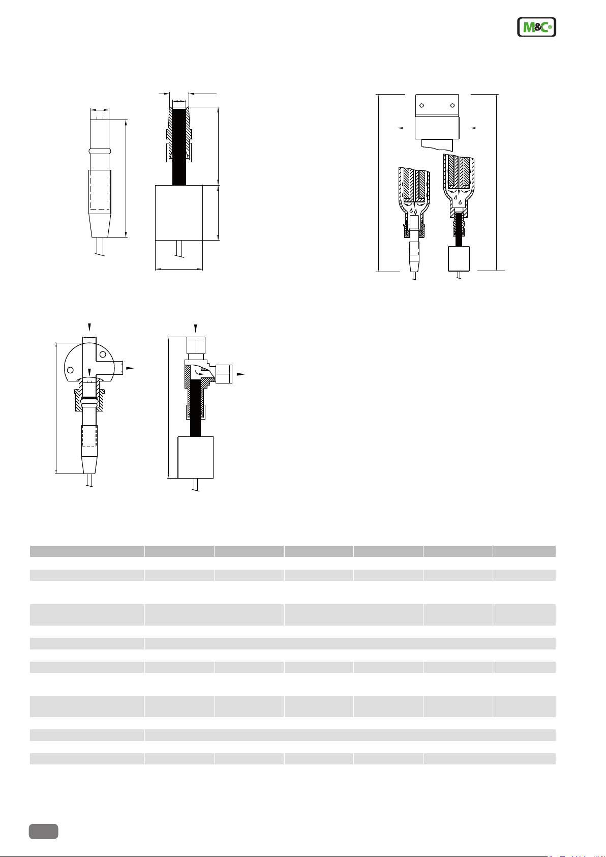
Dimensions
Liquid sensors LA 1S, LA 25S, LA 1 and LA 25
1/4"NPT
ø 12
ca.80
ø 8
LA 1S
LA 25S
ø 30
35 50
Liquid alarm sensors LA 1S and LA 25S with flow
chamber LS and LS 25
sample gas
G1/4"
sample gas
Liquid sensors LA 1S and LA 25S in universal
filter F..-..-D and FSS-..-D
sample gas
universal filter
F-..-D/FSS-..-D
LA1
sample gas
290
LA 25S
LA 1S
sample gas
G1/4"
sample gas
120
LA 25S
LS/LA
115
Dimensions in mm
Technical Data
Sensor series LA
Flow chamber LS LS 25
Part Number 03 E 1001 03 E 3100 03 E 1111 03 E 1120 03 E 1000 03 E 1110
Connection cable
ø 4,2 mm, 2-core
Pressure 0-4 bar g**** 0-25 bar g* (up to 100 bar g*) 0-4 bar g**** 0-25 bar g* (up
Flow 0-1000 l/hr
Operating temperature +80 °C ***
Gas connections ø12 mm G 1/4" i 1/4" NPT a ø8 mm** ø12 mm 1/4" NPT a
Stagnant space, approx. ca. 3 ml ca. 3 ml
Material of sample
contacting parts***
Type of mounting clamping attach-
Mounting position vertical
Electrical conductivity >50 µS/cm
Weight 50 g 60 g 140 g 100 g 50 g 140 g
Line break monitoring yes yes no
Operating in ex-areas no yes no yes
* other pressure ranges -, ** other dimensions -, *** other materials or temperatures on request
**** max. 2 bar when mounted in universal lter
Article numbers for combined lters or ow chamber sets including sensor and electronic controllers can be taken from the current article lists.
®
LA 1S LA 25S LA 1 LA 25
4 m
each additional meter of connection cable = part No. 03E 9001 (03 E 9000 for LA 1 and LA 25), total max. 100 meters
to 100 bar g*)
glass, platinium PVDF,
FPM
wall screw on pipe clamping attach-
ment
SS 316Ti
PVDF
SS 316Ti glass, platinium SS 316Ti
PVDF
screw on
ment
8.1
M&C TechGroup Germany GmbH • Rehhecke 79 • 40885 Ratingen • Germany
info@mc-techgroup.com • www.mc-techgroup.com • Fon +49 2102 935-0 • Fax +49 2102 935-111
Technical specications and illustrations are without
obligation, subject to modications. 09.96/11.06
 Loading...