

Page 1
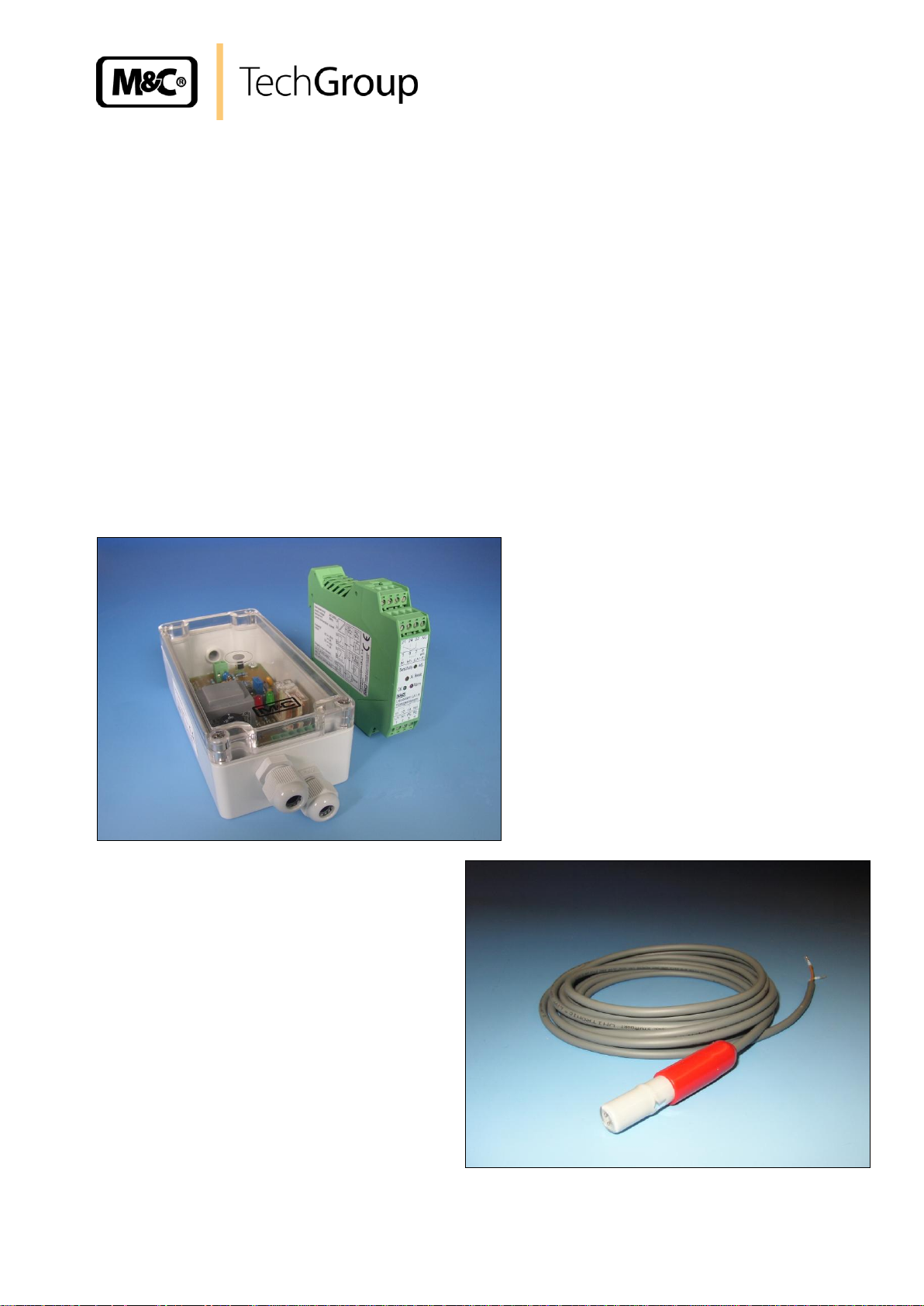
Operating Manual
Liquid alarm sensors for conductive media Series LA
Version LA 1S and LA 25S
and flow chambers LS and LS 25
with electronic controllers LA 1.1, LA 1.4
®
Gas sampling and conditioning technology 5-5.1.1-ME
Page 2

2
This Operating Manual does not claim completeness and may be
subject to technical modifications.
© 01/2006 M&C TechGroup Germany GmbH. Reproduction of this
document or its content is not allowed without permission from M&C.
LA® is a registered trade mark.
2nd Edition: 05/07
Dear customer,
we have made up this operating manual in such a way that all necessary information about the
product can be found and understood quickly and easily.
Should you still have any question, please do not hesitate to contact M&C directly or go through your
appointed dealer. Respective contact addresses are to be found in the annexe to this operating
manual.
Please also contact our homepage www.mc-techgroup.com for further information about our
products. There, you can read or download the data sheets and operating manuals of all M&C
products as well as further information in German, English and French.
Gas sampling and conditioning technology 5-5.1.1-ME
Page 3

3
Contents
1 General information .................................................................................................................... 4
2 Declaration of conformity ........................................................................................................... 4
3 Safety instructions ...................................................................................................................... 5
4 Warranty ....................................................................................................................................... 5
5 Used terms and signal indications ............................................................................................ 6
6 Introduction .................................................................................................................................. 6
7 Application ................................................................................................................................... 7
8 Technical Data ............................................................................................................................. 7
9 Description ................................................................................................................................... 8
10 Receipt of goods and storage .................................................................................................... 8
11 Installation instructions and Dimensions ................................................................................ 9
12 Mounting .................................................................................................................................... 11
12.1 Pre-assembly at works in case of complete control units .................................................. 11
12.2 Mounting of the sensor LA 1S into the universal filter ........................................................ 12
12.3 Mounting of the sensor LA 1S into the flow chamber LS .................................................... 12
12.4 Mounting of the Sensor LA 25S onto the Universal filter .................................................... 13
12.5 Mountage of the Sensor LA 25S into the flow chamber LS 25 ........................................... 13
13 Supply connections .................................................................................................................. 14
13.1 Electrical connections ......................................................................................................... 14
13.1.1 Electronic controller LA-1.1 ....................................................................................... 14
13.1.2 Electronic controller LA-1.4 ....................................................................................... 16
13.2 Pneumatical connections ................................................................................................... 17
14 Starting ....................................................................................................................................... 17
14.1 Starting with a dry sensor ................................................................................................... 17
14.2 Function test ....................................................................................................................... 18
14.3 Adjustment of sensitivity ..................................................................................................... 18
14.4 Adjustment of alarm holding function ................................................................................. 19
15 Closing down ............................................................................................................................. 19
16 Maintenance and repair ............................................................................................................ 20
17 Spare parts list ........................................................................................................................... 21
18 Appendix .................................................................................................................................... 21
List of illustrations
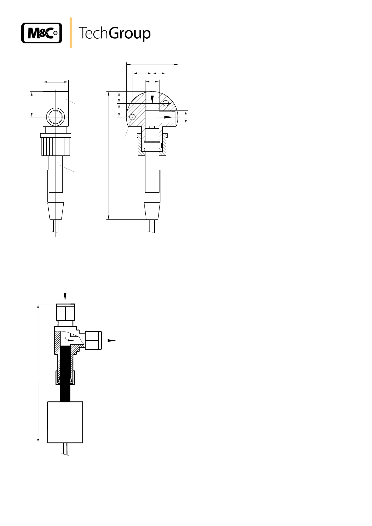
Figure 1 Flow chamber LS with liquid sensor LA 1S .................................................................... 10
Figure 2 Flow chamber LS 25 with liquid sensor LA 25S ............................................................. 10
Figure 3 Liquid alarm sensor LA 1S and LA 25S with universal filter F..-..D and FSS-..-D .......... 11
Figure 4 Mounting of the sensor LA 1S into flow chamber LS ...................................................... 13
Figure 5 Electrical connection and dimensions LA-1.1 ................................................................. 15
Figure 6 Electrical connection and dimensions LA-1.4 ................................................................. 16
Figure 7 Insertion plan of the LA-1.4 ............................................................................................ 17
Figure 8 Flow diagram LA1.1, 115/230V 50/60Hz ........................................................................ 22
Figure 9 Flow diagram LA1.1, 24V AC/DC ................................................................................... 23
Figure 10 Flow diagram LA1.4, 115/230V 50/60Hz ........................................................................ 24
Figure 11 Flow diagram LA1.4, 24V AC/DC ................................................................................... 25
Gas sampling and conditioning technology 5-5.1.1-ME
Page 4
4
Head Office
M&C TechGroup Germany GmbH Rehhecke 79 40885 Ratingen Germany
Telephone: 02102 / 935 - 0
Fax: 02102 / 935 - 111
E - mail: info@mc-techgroup.com
www.mc-techgroup.com
1 GENERAL INFORMATION
The product described in this operating manual has been examined before delivery and left our works
in perfect condition related to safety regulations. In order to keep this condition and to guarantee a
safe operation, it is important to heed the notes and prescriptions made in this operating manual.
Furthermore, attention must be paid to appropriate transportation, correct storage, as well as
professional installation and maintenance work.
All necessary information a skilled staff will need for appropriate use of this product are given in this
operating manual.
2 DECLARATION OF CONFORMITY
CE - Certification
The product described in this operating manual complies with the following EC directives:
EMV-Instruction
The requirements of the EC directive 2004/108/EC “Electromagnetic compatibility“ are met.
Low Voltage Directive
The requirement of the EC directive 2006/95/EC “Low Voltage Directive“ are met.
The compliance with this EC directive has been examined according to DIN EN 61010.
Declaration of conformity
The EU Declaration of conformity can be downloaded from the M&C homepage or directly requested
from M&C.
Gas sampling and conditioning technology 5-5.1.1-ME
Page 5

5
3 SAFETY INSTRUCTIONS
Please take care of the following basic safety procedures when mounting, starting up or
operating this equipment:
Read this operating manual before starting up and use of the equipment. The information and
warnings given in this operating manual must be heeded.
Any work on electrical equipment is only to be carried out by trained specialists as per the regulations
currently in force.
Attention must be paid to the requirements of VDE 0100 (IEC 364) when setting high-power electrical
units with nominal voltages of up to 1000 V, together with the associated standards and stipulations.
Check the details on the type plate to ensure that the equipment is connected to the correct mains
voltage.
Protection against touching dangerously high electrical voltages:
Before opening the equipment, it must be switched off and hold no voltages. This also applies to any
external control circuits that are connected.
The device is only to be used within the permitted range of temperatures and pressures.
Check that the location is weather-protected. It should not be subject to either direct rain or moisture.
The electronic controllers LA-1.1 and LA-1.4 as well as the liquid sensors LA 1S and LA 25S in
combination with this electronic controllers must not be used in hazardous areas.
Installation, maintenance, monitoring and any repairs may only be done by authorized personnel with
respect to the relevant stipulations.
4 WARRANTY
If the equipment fails, please contact M&C directly or else go via your appointed M&C dealer.
We offer a one year warranty as of the day of delivery as per our normal terms and conditions of sale
and assuming technically correct operation of the device. Consumables are hereby excluded. The
terms of the warranty cover repair at the factory at no cost or the replacement at no cost of the
equipment free ex user location. Reshipments must be sent in a sufficient and proper protective
packaging.
Gas sampling and conditioning technology 5-5.1.1-ME
Page 6
6
DANGER!
This means that death, severe physical injuries and/or important
material damages will occur in case the respective safety measures
are not fulfilled.
WA R N ING !
This means that death, severe physical injuries and/or important
material damages may occur in case the respective safety
measures are not fulfilled.
CARE!
This means that minor physical injuries may occur in case the
respective safety measures are not fulfilled.
CA R E !
Without the warning triangle means that a material damage may
occur in case the respective safety measures are not met.
AT T E NT I O N!
This means that an unintentional situation or an unintentional status
may occur in case the respective note is not respected.
NOTE!
These are important information about the product or parts of the
operating manual which require user’s attention.
SKILLED STAFF
These are persons with necessary qualification who are familiar with
installation, use and maintenance of the product.
5 USED TERMS AND SIGNAL INDICATIONS
6 INTRODUCTION
The M&C liquid alarm units series LA® are designed for a continuous and stationary operation and
guarantee a long service life and a minimum maintenance work provided a perfect installation.
Gas sampling and conditioning technology 5-5.1.1-ME
Page 7

Sensor Series LA
®
LA 1S
LA 25S
Flow chamber
LS LS 25
Part Number
03 E 1001
03 E 3100
03 E 1111
03 E 1120
Connection cable
2 m 2 m
ø 4,2 mm, 2-core
each additional meter of connection cable = part No. 03E 9001, total max. 100 meters
Pressure
0 - 4 bar g****
0 - 25 bar g (up to 100 bar g*)
Flow
0 - 1000 l/h
Operating temperature
+80 °C ***
Gas connections
ø 12 mm
G 1/4" i
1/4" NPT a
ø 8 mm **
Stagnant space approx.
3 ml 3 ml
Material of sample
contacting parts ***
glass, platinum
PVDF,
FPM
SS316Ti,
PVDF
SS316Ti
Type of mounting
clamping attachment
wall
screw on
pipe
Mounting position
vertical
Electrical conductivity
>50 µS/cm
Weight
50 g
60 g
140 g
100 g
Electronic Controller Series LA® Type
LA-1.1
LA-1.4
Part Number
230V 50/60Hz
115V 50/60Hz
24V DC
24V AC
03 E 2001*
03 E 2001*
03 E 2001* d
03 E 2001* b
03 E 2006
03 E 2006 a
03 E 2006 d
03 E 2006 d
Mounting
Wall mounting housing Rail mounting housing EN 50022
Sensor inlets
1
Power consumption
2 VA
1VA
Alarm-relay (2x MC/NC/NO)
contact rating
250V DC/AC
DC=50W, AC=500VA, 3A
250V DC/AC
DC=45W, AC=500VA, 2A
Cable inlet
1x terminal range 3mm - 6,5mm
2x terminal range 5mm - 10mm
Electrical connection
Terminals max. 2,5 mm
2
Adjustment of switching point
Via potentiometer after opening of housing
Via potentiometer in the housing front
Distance between sensor and
electronic LA-1..
max. 100m
Line break supervision
yes
Alarm reset**
yes
Protection type
IP65 EN60529
IP20 EN60529
Housing material
Polycarbonate
Polyamide PA 6.6 combustibility class VO
(UL94)
Ambient temperature
-25 °C to +60 °C
Dimensions
B 80xL 160xH 55 mm
B 22,8 x L 100 x H 111 mm
Weight
0,31 kg
0,23 kg
7
7 APPLICATION
Liquid alarm sensors LA 1S and LA 25S are used in gas sample conditioning systems for monitoring
gas cooling and condensate drain-off devices in order to provide protection for downstream analysis
instruments. This simple monitoring device reliably signals the penetration of condensate in the event
of cooling or condensate drain-off equipment being defective and thus avoids expensive down times
as well as high repair costs for analysis instruments.
The electronic controllers LA-1.1 and LA-1.4 are used for feeding and signal processing of the liquid
alarm sensors LA 1S and LA 25S.
In the event of alarm, the power for the sample gas pump or a solenoid valve is to be switched off in
the gas sample conditioning system.
8 TECHNICAL DATA
* other pressure ranges -, ** other dimensions -, *** other materials or temperatures on request
**** max. 2 bar when mounted in universal filter
A Electronic controllers type LA-1.1 LA-1.4
Reversible distribution voltage 230V 50Hz / 115V 60Hz, at works adjusted to 230V 50Hz.
** at works deactivated
Gas sampling and conditioning technology 5-5.1.1-ME
Page 8

8
NOTE!
Only the newly developed electronic controllers as described in the afore
mentioned data sheet from date of construction 04/2006 onwards can be
used for the M&C liquid sensors LA..S.
AT T E NT I O N!
The special electronic controller ER142 Exi (without line break controller)
(Part No.: 03E2009 (a)) must only be used for the intrinsically safe feeding
of the old sensor versions LA 1 or LA 25 being installed in the EX-zone.
For application in combination with the new sensor versions LA 1S and
LA 25S no explosion protection is provided!
9 DESCRIPTION
The M&C liquid sensors LA..S works on the principle of electrical conductivity from 20 µS/cm
conductance. In order to avoid electrolytic effects on the sensor surface, the sensors are powered with
alternating current.
The M&C LA..S liquid sensors are constructed in such a way that any droplets of liquid in the sample
gas are attracted under gravity to the sensor surface and even the smallest liquid droplets trigger a
sure and rapid alarm.
The LA 1S sensor is defined for operating pressure up to 4 bar and LA 25S for up to 25 bar. The
sensor protection corresponds to type IP65 EN 60529.
The LA 1S sensor with its 12 mm diameter glass body is mounted in the GL connection of a F..-..-D
universal filter or in the LS flow chamber. The LA 25S sensor has got a 1/4" special male connector
for mounting in the FSS..-D universal filter or for mounting in 8 mm tubes using a special union tee
connector LS 25.
When mounting the universal filters and the flow chamber, the gas inlet and gas
outlets can be rotated through 180° during assembly.
Two mounting types are available, wall-mounting LA1.1 and rail-mounting LA1.4.
A line break supervision is integrated for sure operation. There are two LED’s for displaying
operational and fault status as well as two potential-free changeover contacts with "safety-first"
switching action for sure alarm signalling. The electronic controllers are equipped with an alarm reset
that may be activated or deactivated. During delivery, it is not activated.
By using one of the contacts, a pump or a solenoid valve in the gas conditioning system can be
switched directly and the second contact can be used as a status alarm.
The switching point of the electronic controller LA-1.. is adjustable via a potentiometer. At works, a
standard alignment is made for a conductivity of 100µS/cm.
10 RECEIPT OF GOODS AND STORAGE
The liquid alarm series LA® are normally delivered in 2 packing units:
1. Universal filter F.-..-D or flow chamber LS and liquid sensor LA ..S
2. Electronic controller LA-1...
Please take the liquid alarm units LA... and eventual special accessories carefully out of the
packaging material immediately after arrival, and compare the goods with the items listed on the
packing list.
Check the goods for any damage caused during delivery and, if necessary, notify your transport
insurance company without delay of any damage discovered.
Gas sampling and conditioning technology 5-5.1.1-ME
Page 9

NOTE!
The liquid alarm components should be stored in a protected frost-free
area !
NOTE!
NOTE!
During mounting, the gas inlet and gas outlet of the universal filters and
the flow chamber can be turned by 180°.
9
11 INSTALLATION INSTRUCTIONS AND DIMENSIONS
The liquid alarm sensor LA ..S is used for detecting liquids and is to be installed behind the gas
dehydration devices, e.g. behind a gas cooler, but always on the deepest point of the installation. This
is provided by the universal filters F.-..-D and the flow chambers LS or LS 25.
The filters F.-..D and the flow chambers LS are designed for wall mounting and are mounted by using
the 2 fastening screws.
The operating position is exclusively vertical, only then an immediate alarm is given in case of liquids
breaking through.
When mounting the devices outside, no special protecting measures are necessary provided that in
winter the ambient temperature does not fall below the dew point temperature of the measuring gas.
The gas inlet and outlet can be positioned on the left side or the right side of the filter, all you need to
do is to shift the blue angle bracket. Another inlet connection – supplied with a blind plug - is vertically
available. The flow chamber has got the gas inlet on the vertical position and the gas outlet according
to the fastening on the right side or the left side.
The flow direction is marked with arrows.
The standard gas connections of the universal filters F.-..-D and the flow chamber LS are G1/4" i.
The gas connections can be selected depending on the application, either soft and flexible tubes out
of PVC, Novoprene, FPM etc. or rigid tubes out of synthetic material like PTFE or metal e.g. stainless
steel.
For the suitable connection fittings please look into our range of products.
Gas sampling and conditioning technology 5-5.1.1-ME
Page 10
10
G1/4"
115
LA1
25
12
13
ø50
G1/4"
17 12
ø5
25
LS
Sample gas
Sample gas
LA 25S
LS 25
DN 8
DN 8
120
LA 1S
LS
Figure 1 Flow chamber LS with liquid sensor LA 1S
Figure 2 Flow chamber LS 25 with liquid sensor LA 25S
Gas sampling and conditioning technology 5-5.1.1-ME
Page 11
Universal filter
F..-..D / FSS-..-D
Sample gas
Sample gas
LA 25S
LA 1S
290
290
NOTE!
Please check before assembling that the clamping ring GL25-12 of
PTFE/silicone is not defect and is placed on the sensor, the white PTFE
surface pointing to the viewer (medium side). Only then, the necessary
leak-proofing is guaranteed.
11
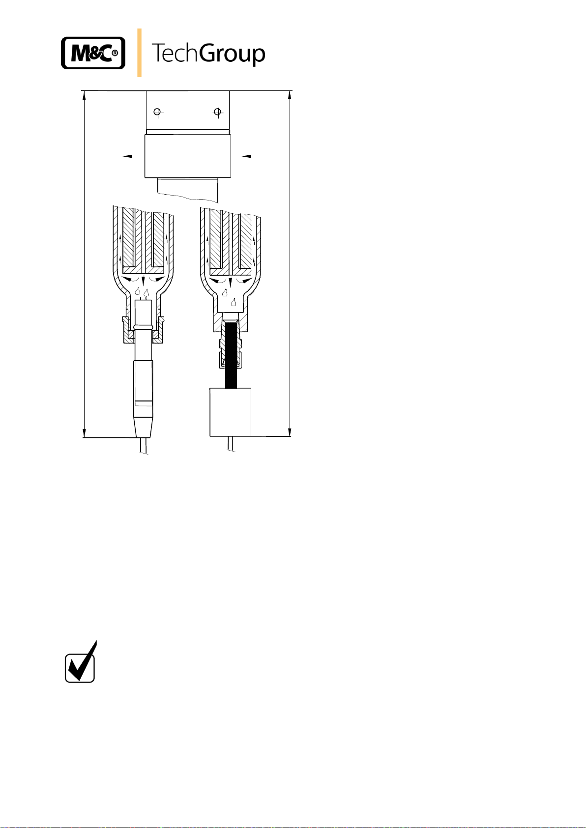
Figure 3 Liquid alarm sensor LA 1S and LA 25S with universal filter F..-..D and FSS-..-D
12 MOUNTING
12.1 PRE-ASSEMBLY AT WORKS IN CASE OF COMPLETE CONTROL UNITS
In case you order a complete control unit consisting of liquid sensor, universal filter or flow chamber
and electronic controller, the mounting of the sensor into the respective installation device is effected
at works as far as possible.
For transportation, the sensor LA 1S of the universal filters F.-..-D is pre-assembled. The only thing
left to do is to mount the sensor LS 1S hand-tight by clockwise rotation of the red union nut GL25 into
the below GL connection of the filter.
The sensor LA 25S is to be screwed with the pre-assembled G1/4“ fitting into the thread of the
stainless steel filter body by using a tape of Teflon.
If the sensors are delivered in connection with a flow chamber, both are completely pre-assembled.
Gas sampling and conditioning technology 5-5.1.1-ME
Page 12

12
NOTE!
The PTFE/Silicone clamping ring GL25-12 must not be defective. Only then,
the necessary tightness is guaranteed.
NOTE!
The O-ring must not be defective. Only then, the necessary tightness is
guaranteed.
12.2 MOUNTING OF THE SENSOR LA 1S INTO THE UNIVERSAL FILTER
In case the client has selected single components, the mounting of the sensor has to be effected as
follows:
Dismount the red GL25 union nut incl. the inside GL25-12 clamping ring from the filter.
Tear the red anti-kink socket of the cable on the sensor LA 1S by slight swinging movements
backwards in direction of the connection cable of the sensor body.
Push the GL25 union nut on the sensor body with its inside thread showing to the sensor
beginning (platinum electrodes) backwards in direction of the red cable anti-kink.
Push the GL25-12 clamping ring with the white PTFE surface showing to the sensor beginning
(medium side) over the swelling on the sensor body.
Push the red union nut with clamping ring against the swelling on the sensor body.
Push the red anti-kink socket of the cable by slight swinging movements onto the sensor body
again.
Screw the red GL25 union nut with sensor onto the GL connection thread of the filter.
12.3 MOUNTING OF THE SENSOR LA 1S INTO THE FLOW CHAMBER LS
If the client has selected single components, the mounting of the sensor has to be effected as follows:
Dismount the union nut incl. the inside O-ring and the pressing ring from the chamber body.
Tear the red anti-kink cable socket by slight swinging movements from the sensor body over
the connecting cable.
Push the union nut with its inside threading showing to the sensor beginning (platinum
electrodes) over the connection cable onto the sensor body.
Push the PVDF pressing ring and afterwards the black FPM O-ring on the electrodes’ side up
to the swelling on the sensor body.
Push the union nut on the sensor body up to the swelling.
Put the sensor connection cable again through the black anti-king cable socket and push the
socket by slight swinging movements approx. 15 mm onto the sensor body.
Mount the sensor with union nut into the below connection of the flow chamber.
Gas sampling and conditioning technology 5-5.1.1-ME
Page 13

Union nut
Antikink
Item
Part-No.
Description
1
90 E 1000
FPM O-ring 14
2
90 E 1010
PVDF – pressing ring 16
3
03 E 1001
Liquid sensor LA 1S
with 4m connection cable
4
03 E 3100
Flow chamber LS
with union nut
13
Figure 4 Mounting of the sensor LA 1S into flow chamber LS
12.4 MOUNTING OF THE SENSOR LA 25S ONTO THE UNIVERSAL FILTER
If the client hat selected single components, the mounting of the sensor has to be effected as follows:
Screw the attached mounting fitting with a Teflon tape into the filter body.
Put the sensor with pre-assembled union nut and the pre-assembled pressing and cutting ring
into the fitting and draw up the union nut hand-tight. Then draw the union nut with a flat key
exactly 1 ¼ rotations. Now, it is mounted correctly.
12.5 MOUNTAGE OF THE SENSOR LA 25S INTO THE FLOW CHAMBER LS 25
If the client has selected single components, the mounting of the sensor has to be effected as follows:
Put the sensor with pre-assembled union nut and the pre-assembled pressing and cutting ring
into the flow chamber and draw the union nut hand-tight. Then draw the union nut with a flat
key exactly 1 ¼ rotations. Now, it is mounted correctly.
Gas sampling and conditioning technology 5-5.1.1-ME
Page 14

14
W A R NI N G !
Incorrect supply voltage may destroy the equipment. Please take
care of the correct voltage as indicated on the type plate!
The supply voltage may vary from the indication on the type plate
by max. ± 10%.
NOTE!
When setting high-power electrical units with nominal voltages of
up to 1000V, attention must be paid to the requirement of IEC 364
(DIN VDE 0100) as well as the associated standards and
stipulations!
NOTE!
Only the sensor types LA 1S and LA 25S provide a line break
control.
NOTE!
The connection cables of the sensors LA 1S and LA 25S are
normal 2-wire lines and can be extended up to 100m via usual
terminals if necessary.
The connection cables of the old sensors LA 1, LA 25 and LA 1-H
are special HF lines that must not be lead and extended via
normal terminals because those terminals interrupt the protective
cover of the line.
13 SUPPLY CONNECTIONS
13.1 ELECTRICAL CONNECTIONS
The electronic controllers LA-1.1 are equipped with a mains selector switch S3 for 230 / 115 V. At
works, this selector switch is adjusted to 230 V. Check the desired voltage before starting and, if
necessary, change the selector switch by using a screw driver.
The electronic controllers LA-1.4 in 24 V version are suitable for both, constant voltage and alternating
voltage.
When fixing the sensor cable to the installation, take care that the cable is not too short in order to be
able to dismount the sensor without problem for control or cleaning purposes.
13.1.1 ELECTRONIC CONTROLLER LA-1.1
For the electrical connection, the following steps are to be taken (see figure 4):
Loosen the 4 lid screws and remove the lid.
Lead the connection cables through the respective clamp fitting.
The electrical connection of the sensor LA 1S or LA 25S is made according the colours on the
terminals 5 = brown and 6 = white. All sensors of type LA 1, LA 25 and LA 1-H are to be
connected to terminals 5 = brown and 8 = white. In this case, a bridge must be installed
Gas sampling and conditioning technology 5-5.1.1-ME
between terminals 6 and 7.
Page 15

NOTE!
If the the old sensor LA 1, LA 25 or LA 1-H is connected the same way as
the new sensor LA 1S, the function of the electronic is inverted: no liquid =
alarm, liquid = o.K.
NOTE!
If a new sensor LA 1S is connected the same way as the old sensor LA 1,
LA 25 or LA 1-H no line break control is existing.
15
The voltage supply takes place on terminals 1 = L, 2 = N and 3 = PE.
The alarm is to be connected to terminals 11, 21 = centre contact, 12, 22 = alarm and 14, 24 =
o.k..
Figure 5 Electrical connection and dimensions LA-1.1
Gas sampling and conditioning technology 5-5.1.1-ME
Page 16

16
13.1.2 ELECTRONIC CONTROLLER LA-1.4
For the electrical connection, the following steps have to be carried out (see also figure 5):
The electrical connection of the sensor LA 1S or LA 25S is to be made on terminals 5 = brown
and 6 = white. Old sensors of type LA 1, LA 25 and LA 1-H are to be connected to terminals 5
= brown and 8 = white. In this case, you must install a bridge between terminals 6 and 7.
The voltage supply is to be effected on the terminals 1 = L, 2 = N and 4 = PE.
The alarms are to be connected on terminals 11, 21 = alarm, 12, 22 = centre contact and 14,
24 = o.k..
Figure 6 Electrical connection and dimensions LA-1.4
Gas sampling and conditioning technology 5-5.1.1-ME
Page 17

17
Figure 7 Insertion plan of the LA-1.4
13.2 PNEUMATICAL CONNECTIONS
For the connection of the measuring gas lines and when using the universal filters F..-..-D and the flow
chamber LS, you must use two fittings with thread G1/4“ a and the corresponding tube and pipe
connection. The screw fittings have to be screwed into the universal filter respectively the flow
chamber by using PTFE tape.
The flow chamber LS 25 is already equipped with screw fittings for 8mm tubes.
Regarding mounting of the tube and pipe lines:
Dismount the union nuts as well as the pressing and cutting rings from the fitting.
Push the union nut, then the pressing ring, then the cutting ring onto the tube resp. Pipe line.
Put the tube resp. Pipe into the fitting and draw up the union nut hand-tight.
Then the stainless steel nuts have to be drawn up by using a flat key by exactly 1 ¼ rotations
and it is correctly mounted.
14 STARTING
14.1 STARTING WITH A DRY SENSOR
Switch on the mains voltage, the green LED of the electronic controllers LA 1.1 resp. LA1.4 are
beaming.
The liquid alarm control is ready for work!
Gas sampling and conditioning technology 5-5.1.1-ME
Page 18

18
NOTE!
If the sensor is dry, the green LED indicates that the instrument is
in operating condition, the green LED is out when the red LED is on
and signalizes a liquid alarm.
NOTE!
If the alarm is not activated when executing the function test, the
sensor, the electronic controller and the connections must be
examined.
NOTE!
The sensor LA 1S is only able to detect condensate with a
conductance ration of min. 20 µS/cm.
Therefore, it is advisable to check the sensor function with the
eventually occuring condensate. For this purpose, dismount the
sensor and execute the above described function test with the
respective condensate.
W A R NI N G !
Aggressive condensate possible. Wear protective glasses and
protective clothes when dismounting, repairing or cleaning the
sensor!
In case the read alarm LED is beaming, there is liquid on the sensor, or there is a line break, or you
must do an adjustment of the sensitivity (see chapter 14.3).
14.2 FUNCTION TEST
The responsiveness of the sensors LA 1S and LA 25S should be examined before the first starting
and afterwards two times a year and is to be effected as follows:
Dismount the sensor LA 1S resp. LA 25S.
Make a short-circuit of the sensor electrodes by using a humid finger.
The electronic controller LA-1.1 resp. LA-1.4 indicates an alarm, i.e. the red LED is beaming.
After the function test, dry the electrodes with a cloth.
Remount the sensor into the receiver part.
For the sensors LA 1S and LA 25S, a parting of a cable can be simulated by disconnecting a
connection lead on the electronic controller. Also in this case, the electronic controller LA 1.1 resp.
LA1.4 must immediately indicate alarm, i.e. the red LED must beam.
14.3 ADJUSTMENT OF SENSITIVITY
At works, a standard adjustment of the electronic controllers LA-1.1 and LA-1.4 is executed for a
conducting capacity of 100µS/cm. Hereby, the length of the sensor’s connection cable does not
matter.
In case a permanent alarm is given and the red LED is permanently beaming after the initial starting in
spite of the fact that the sensor is dry, or in case the sensor is humid and no alarm is given, the
sensitivity of the sensor must be adjusted.
Gas sampling and conditioning technology 5-5.1.1-ME
Page 19

NOTE!
Should there be condensate with a low conducting capacity, do not shortcircuit the sensor. Moisten instead the sensor (that has be cleaned with
distilled water) with the respective condensate.
19
Range of adjustment on the electronic controllers: 50µS/cm … 1mS/cm.
For an adjustment of sensitivity, the following steps have to be executed:
Remove the 4 lid screws of the electronic controller LA-1.1 and remove the lid.
Dismount the sensor, clean and dry the electrodes.
In case of permanent alarm with a dry and clean sensor: Turn on the potentiometer P1 (LA-
1.1) resp. Sensitivity adj. (LA-1.4) anticlockwise (lower sensitivity) until the alarm is out. Then
make a short-circuit with a humid finger. Then, the electronic controller LA-1.. must
immediately indicate alarm, i.e. the red LED must be beaming.
In case the alarm is not activated while making the short-circuit of the sensor electrodes
with a humid finger: Turn on the potentiometer P1 (LA-1.1) resp. Sensitivity adj. (LA-1.4) in
clockwise direction (higher sensitivity) until the alarm is indicated, i.e. the red LED is beaming.
Screw again the 4 lid screws of the electronic controller LA-1.1.
Dry the electrodes with a cloth and mount the sensor again.
14.4 ADJUSTMENT OF ALARM HOLDING FUNCTION
Optionally, you can configure a self-holding of the alarm. For this purpose, you have to execute a
manual reset in the event of an alarm.
For configuration of the alarm holding function, you have to execute the following steps:
Remove first the 4 lid screws and then the lid of the electronic controller LA-1.1.
For the rail mounting version LA-1.4, loosen the above and below closing behind the terminals
by means of a screw driver. Then pull the printed board together with the housing front out of
the back housing part.
Plug the jumper on JP1 from position: 2-3 (no alarm memory function) to position 1-2 (see
figure 4 resp. 6).
Screw the lid again on electronic controller LA-1.1.
Push the printed board again into the housing of electronic controller LA-1.4.
The manual reset has to be released on the electronic controllers LA 1.1 and LA1.4 by actuating the
key button S1 resp. Al. Reset. In case of the electronic controller LA 1.1, you have to remover the
housing lid for this purpose (see figure 4). In case of electronic controller LA 1.4, you have to actuate
the key button in the housing front (Al. Reset).
15 CLOSING DOWN
No special measures have to be respected for closing down.
Gas sampling and conditioning technology 5-5.1.1-ME
Page 20

20
NOTE!
Please take care of the specific installation and process safety
measures before executing any maintenance and repair work!
AT T E NT I O N!
In case of liquid breaking through, the total conditioning unit
including the receiving part with sensor must be dried and
cleaned.
NOTE!
Aggressive condensate possible. Wear safety glasses and
respective protective clothes when dismounting, repairing or
cleaning the sensor!
16 MAINTENANCE AND REPAIR
The liquid control units series LA® are working maintenance-free during a long period of time.
It may be that the electrodes of the sensors LA 1S resp. LA 25S are dirty from deposits. Please use a
cloth for cleaning, eventually in connection with a solvent of cleaning material. For cleaning, the sensor
has to be dismounted.
In case of a defect of the electronic, please send the instrument for repair to M&C Products.
Gas sampling and conditioning technology 5-5.1.1-ME
Page 21

Liquid alarm sensor unit LA...
(V) Consumables, (E) Recommended spare parts, (T) Spare parts
Recommended quantity for
operation during a period of
xxx years
V/E/T 1 2
3
Sensor LA 1S / LS:
90 E 1000
FPM O-Ring (14)
E 2 4
8
90 E 1010
PVDF-Ring (16)
E 2 4
8
Sensor LA 1S / F.-..-D:
90 F 0025
PTFE Sealing ring GL25-12ø
E 2 4
8
91 F 0020
Union nut GL25 (read)
E 1 2
3
Sensor LA 1S, LA 25S:
03 E 1001
Liquid sensor LA 1S with 4m connection cable
T 1 1
1
03 E 1111
Liquid sensor LA 25S with 4m connection cable
T 1 1
1
03 E 9001
Connection cable LA.., per meter
T - -
-
21
17 SPARE PARTS LIST
The requirement of wear, tear and spare parts depend on specific operating conditions. The quantities
we recommend are based on experience and are not binding.
18 APPENDIX
Flow diagram LA1.1, 115/230V 50/60Hz
Flow diagram LA1.1, 24V AC/DC
Flow diagram LA1.4, 115/230V 50/60Hz
Flow diagram LA1.4, 24V AC/DC
For additional product documentation please look into our home page:
www.mc-techgroup.com
Gas sampling and conditioning technology 5-5.1.1-ME
Page 22

22
Figure 8 Flow diagram LA1.1, 115/230V 50/60Hz
Gas sampling and conditioning technology 5-5.1.1-ME
Page 23

23
Figure 9 Flow diagram LA1.1, 24V AC/DC
Gas sampling and conditioning technology 5-5.1.1-ME
Page 24

24
Figure 10 Flow diagram LA1.4, 115/230V 50/60Hz
Gas sampling and conditioning technology 5-5.1.1-ME
Page 25

25
Figure 11 Flow diagram LA1.4, 24V AC/DC
Gas sampling and conditioning technology 5-5.1.1-ME
 Loading...