

Page 1
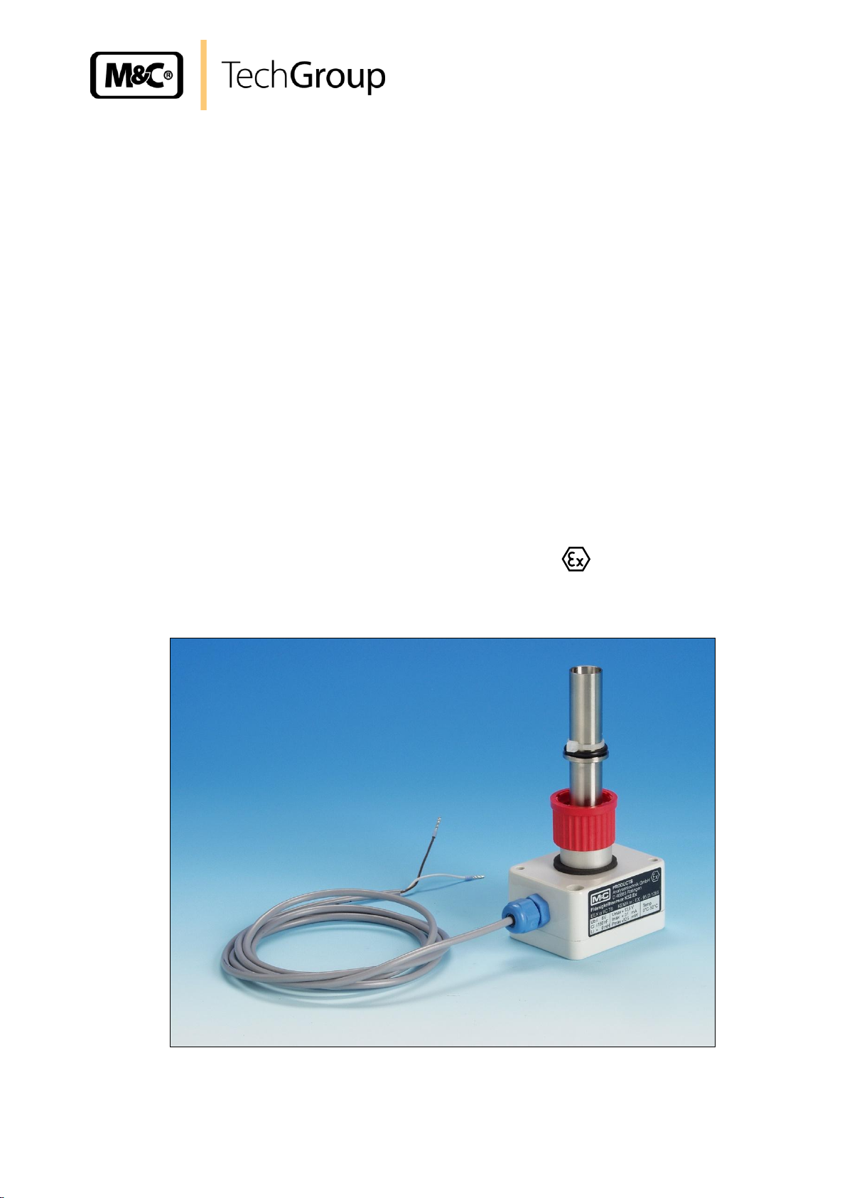
Operating Manual
Liquid Alarm Sensor KS2 / KS2.Ex
for non-conductive and conductive media
Gas sampling and conditioning technology 5-5.3 ME
Page 2

2
This Operating Manual does not claim completeness and may be
subject to technical modifications.
© 10/2004 M&C TechGroup Germany GmbH. Reproduction of this
document or its content is not allowed without permission from
M&C.
2nd Edition: 02/2009
Dear customer,
we have made up this operating manual in such a way that all necessary information about the
product can be found and understood quickly and easily.
Should you still have any question, please do not hesitate to contact M&C directly or go through your
appointed dealer. Respective contact addresses are to be found in the annexe to this operating
manual.
Please also contact our homepage www.mc-techgroup.com for further information about our
products. There, you can read or download the data sheets and operating manuals of all M&C
products as well as further information in German, English and French.
Gas sampling and conditioning technology 5-5.3 ME
Page 3

3
Content
1 General information ....................................................................................................................... 4
2 Declaration of conformity ............................................................................................................. 4
3 Safety instructions ........................................................................................................................ 5
4 Warranty ......................................................................................................................................... 5
5 Used terms and signal indications .............................................................................................. 6
6 Application ..................................................................................................................................... 7
7 Technical data ................................................................................................................................ 8
8 Description ..................................................................................................................................... 9
9 Function ........................................................................................................................................ 10
9.1 Connection and Adjustment of the sensor type KS2 at the electronic FA1.1 ......................... 10
9.2 Connection and Adjustment of the sensor type KS2 at the electronic FA1.4 ......................... 10
9.3 Connection of the sensor type KS2.ex to the electronics WE77/Ex1 ..................................... 11
9.4 Connection of the sensor type KS2.ex to the electronics KFA6-SR2-Ex1.W ........................ 11
9.5 Adjustment of the Sensor type KS2.Ex ................................................................................... 12
10 Cleaning of the sensor ................................................................................................................ 13
11 Spare parts list ............................................................................................................................. 14
12 Appendix ...................................................................................................................................... 14
List of illustrations
Figure 1 KS2 / KS2.Ex Liquid-Sensor ............................................................................................... 7
Figure 2 KS2.. liquid sensor for level monitoring in the condensate pot type TG1 ............................ 9
Figure 3 Liquid alarm-sensor KS.2 / KS2.Ex in a Universal filter F..-..-D .......................................... 9
Figure 4 Electronic KFA6-SR2-Ex1.W (left) and terminal box KS2.Ex respectively WE77/Ex1 ....... 12
Figure 5 Wiring diagram KS2.Ex and KFA6-SR2-Ex1.W respectively WE77/Ex1 ........................... 12
Figure 6 Mounting of the sensor type KS2 ....................................................................................... 15
Gas sampling and conditioning technology 5-5.3 ME
Page 4

4
Head Office
M&C TechGroup Germany GmbH Rehhecke 79 40885 Ratingen Germany
Telephone: 02102 / 935 - 0
Fax: 02102 / 935 - 111
E - mail: info@mc-techgroup.com
www.mc-techgroup.com
1 GENERAL INFORMATION
The product described in this operating manual has been examined before delivery and left our works
in perfect condition related to safety regulations. In order to keep this condition and to guarantee a
safe operation, it is important to heed the notes and prescriptions made in this operating manual.
Furthermore, attention must be paid to appropriate transportation, correct storage, as well as
professional installation and maintenance work.
All necessary information a skilled staff will need for appropriate use of this product are given in this
operating manual.
2 DECLARATION OF CONFORMITY
CE - Certification
The product described in this operating manual complies with the following EC directives:
EMV-Instruction
The requirements of the EC directive 2004/108/EC “Electromagnetic compatibility“ are met.
Low Voltage Directive
The requirement of the EC directive 2006/95/EC “Low Voltage Directive“ are met.
The compliance with this EC directive has been examined according to DIN EN 61010 as well as DIN
57721 for the voltage test of heating elements.
Declaration of conformity
The EU Declaration of conformity can be downloaded from the M&C homepage or directly requested
from M&C.
Gas sampling and conditioning technology 5-5.3 ME
Page 5

5
3 SAFETY INSTRUCTIONS
Please take care of the following basic safety procedures when mounting, starting up or
operating this equipment:
Read this operating manual before starting up and use of the equipment. The information and
warnings given in this operating manual must be heeded.
Any work on electrical equipment is only to be carried out by trained specialists as per the regulations
currently in force.
Attention must be paid to the requirements of VDE 0100 (IEC 364) when setting high-power electrical
units with nominal voltages of up to 1000 V, together with the associated standards and stipulations.
Check the details on the type plate to ensure that the equipment is connected to the correct mains
voltage.
Protection against touching dangerously high electrical voltages:
Before opening the equipment, it must be switched off and hold no voltages. This also applies to any
external control circuits that are connected.
The device is only to be used within the permitted range of temperatures and pressures.
Check that the location is weather-protected. It should not be subject to either direct rain or moisture.
Only the especially marked liquid sensor KS2.EX is allowed to be operated in hazardous areas.
Installation, maintenance, monitoring and any repairs may only be done by authorized personnel with
respect to the relevant stipulations.
4 WARRANTY
If the equipment fails, please contact M&C directly or else go via your appointed M&C dealer.
We offer a one year warranty as of the day of delivery as per our normal terms and conditions of sale
and assuming technically correct operation of the device. Consumables are hereby excluded. The
terms of the warranty cover repair at the factory at no cost or the replacement at no cost of the
equipment free ex user location. Reshipments must be sent in a sufficient and proper protective
packaging.
Gas sampling and conditioning technology 5-5.3 ME
Page 6
6
DANGER!
This means that death, severe physical injuries and/or important
material damages will occur in case the respective safety measures
are not fulfilled.
W ARN IN G !
This means that death, severe physical injuries and/or important
material damages may occur in case the respective safety
measures are not fulfilled.
CARE!
This means that minor physical injuries may occur in case the
respective safety measures are not fulfilled.
CAR E!
Without the warning triangle means that a material damage may
occur in case the respective safety measures are not met.
ATT ENT ION !
This means that an unintentional situation or an unintentional status
may occur in case the respective note is not respected.
NOTE!
These are important information about the product or parts of the
operating manual which require user’s attention.
SKILLED STAFF
These are persons with necessary qualification who are familiar with
installation, use and maintenance of the product.
5 USED TERMS AND SIGNAL INDICATIONS
Gas sampling and conditioning technology 5-5.3 ME
Page 7

7
PG 7
ø16
135
65 x 50
Sleeve nut GL25/18
Chemraz* O-ring 15
KS 2
6 APPLICATION
Liquid alarm sensors are used in gas sample conditioning systems for monitoring gas cooling and
condensate removal devices in order to provide protection for downstream analysis instruments. This
monitoring device KS2 / KS2.Ex reliably signals the penetration of non conductive (e.g. alcohol)
and conductive (e.g. water) liquid in the event of cooling or condensate removal equipment being
defective, thus avoiding expensive down time as well as high repair costs for analysis instruments.
In the event of an alarm, we recommend to switch off the power supply for the sample gas or a
solenoid valve in the sample conditioning system.
* Chemraz is a Greene Tweed Trademark
Figure 1 KS2 / KS2.Ex Liquid-Sensor
Gas sampling and conditioning technology 5-5.3 ME
Page 8

7 TECHNICAL DATA
Sensor
KS2
KS2 Peek
KS2.Ex
Part No.
03E4100
03E4110
03E4200
Pressure
max. 2 bar abs.
max. 11 bar abs.
max. 2 bar abs.
Max. operating temperature
0°C to +60°C
0°C to +50°C
Liquid alarm limit
1,5ml
Material of sample
contacting parts
PTFE, Chemraz,
SS316Ti
Peek, Chemraz,
SS316Ti
PTFE, Chemraz, SS316Ti
Sample connection Standard
(Fitting for mounting in
stainless steel filter:
connector GE SS ½“NPT18mm Part No.. 09V2317)
ø16 mm for GL25
ø18 mm for
mounting in
stainless steel filter
FSS...-D1/2“NPT
ø16 mm for GL25
Option sample connection
ø18 mm, Part No..: 03E9400
(Fitting for mounting in
stainless steel filter:
connector GE SS ½“NPT18mm Part No.. 09V2317)
for mounting in
stainless steel filter
FSS...-D1/2“NPT
for mounting in stainless
steel filter FSS...D1/2“NPT
Method of mounting /
mounting position
clamping attachment / for liquid alarm vertical with opening
upwards
Max. voltage / current /
power consumption
13,5V / 31 mA / 125 mW
Inner capacity max.
150 nF
Inner inductivity max.
0 mH
Power supply
8-12VDC
feeding via FA1.4 or FA1.1
8V DC / max.2,4mA
operating: < 1,4 mA alarm
Connection cable, length 1,5
m standard
3 x 0,25mm²
2 x 0,25mm²
Cable
capacity
inductivity
200pF/m
1µH/m
Protection
IP 54 DIN 40050
II 1 G EEx ia IIC T6
KEMA 03ATEX1006
Weight
190 g
8
Gas sampling and conditioning technology 5-5.3 ME
Page 9

9
max.
TG 1
KS 2
42
58
ø5
13
305
*
G1/4" i.
G1/4" i.
G1/4" i.
* constructional size 410mm
KS 2
8 DESCRIPTION
The M&C liquid sensor KS2 / KS2.Ex works on the principle of capacitive measurement and is
suitable for non-conductive and conductive media. A pre-amplifier is integrated in the sensor housing
and is connected with the necessary external electronic controller via 2- resp. 3-wire. For the sensor
type KS2 the required electronic controller is available in various versions, FA1.1 or FA1.4 and is
described in a separate data sheet. The M&C liquid sensor KS2.Ex for applications in hazardous
areas and media should only be applied in connection with electronic controller WE77.Ex1, KFA6-
SR2-Ex1.W or an electronic with the same performance data (see chapter 9.4). For electronics with
the same performance data there is no guarantee for problemless operation. The M&C KS2 / KS2.Ex
liquid sensor is constructed in such a way that any droplets of liquid in the sample gas are attracted
directly to the active sensor surface. Even small liquid droplets will trigger a sure and rapid alarm. The
sensors can be mounted with the 16mm stainless steel body in the GL-25 connector of the
Universal filter
F..-..-D or the condensate pot TG1 or in the flow chamber LS/KS.
Figure 2 KS2.. liquid sensor for level monitoring in the condensate pot type TG1
In the event of condensate breakthrough, the filter acts as a buffer vessel preventing immediate liquid
penetration.
Figure 3 Liquid alarm-sensor KS.2 / KS2.Ex in a Universal filter F..-..-D
Gas sampling and conditioning technology 5-5.3 ME
Page 10

10
NOTE!
A sensor with high sensitivity can cause false alarms.
NOTE!
A sensor with high sensitivity can cause false alarms.
9 FUNCTION
9.1 CONNECTION AND ADJUSTMENT OF THE SENSOR TYPE KS2 AT THE
ELECTRONIC FA1.1
Link the sensor to the electronic FA1.1 (see also manual 5-6.10ME)
KS2 terminal X4/3 to FA1.1 terminal 15 (yellow)
KS2 terminal X4/2 to FA1.1 terminal 17 (white)
KS2 terminal X4/1 to FA1.1 terminal 18 (brown)
Adjustment with „dry“ sensor:
Turn the potentiometer to the left until the green LED is OFF and the red LED is ON.
Turn the potentiometer very slowly to the right. After the green LED is ON, turn the potentiometer
for another 0,5 rotations to the right.
Checking the sensibility:
Test the sensor with the condensate of your application, if possible. A condensate quantity of 1,5 ml
effects the alarm release. The sensor can be adjusted to a higher sensibility if the potentiometer is
turned to the left.
9.2 CONNECTION AND ADJUSTMENT OF THE SENSOR TYPE KS2 AT THE
ELECTRONIC FA1.4
Link the sensor to the electronic FA1.4 (see also manual 5-6.10ME)
KS2 terminal X1/3 to FA1.4 terminal 15 (yellow)
KS2 terminal X1/2 to FA1.4 terminal 17 (white)
KS2 terminal X1/1 to FA1.4 terminal 18 (brown)
Adjustment with „dry“ sensor:
Turn the potentiometer to the left until the green LED is OFF and the red LED is ON.
Turn the potentiometer very slowly to the right. After the green LED is ON, turn the potentiometer
for another 0,5 rotations to the right.
Checking the sensibility:
Test the sensor with the condensate of your application, if possible. A condensate quantity of 1,5 ml
effects the alarm release. The sensor can be adjusted to a higher sensibility if the potentiometer is
turned to the left.
Gas sampling and conditioning technology 5-5.3 ME
Page 11

11
NOTE!
The bridge between the connecting points 3 and 4 of the electronics
WE77/Ex1 guarantees a „safty-first“ alarm release (alarm in case of voltage
loss and parting of the cable).
NOTE!
If the bridge is missing or switched between the connecting points 4 and 5 of
the electronics WE77/Ex1 the alarm is not working in a „safty-first“ mode (no
alarm in case of voltage loss).
9.3 CONNECTION OF THE SENSOR TYPE KS2.EX TO THE ELECTRONICS WE77/EX1
The function is as follows:
dry sensor : LED „ON“ contact MC-NO terminal 7 and 9 closed Sensor current > 1,7 mA
wet sensor : LED „OFF“ contact MC-NC terminal 7 and 8 closed Sensor current < 1,4 mA
Brigde between connecting points 4 and 5 or missing bridge
The sensor current is on a very low level. Therefore we recommend to switch a resistance of 10k
parallel to the sensor to increase the level.
The function than is as follows:
dry sensor : LED „OFF“ contact MC-NC terminal 7 and 8 closed Sensor current > 1,7 mA
wet sensor : LED „ON“ contact MC-NO terminal 7 and 9 closed Sensor current < 1,4 mA
9.4 CONNECTION OF THE SENSOR TYPE KS2.EX TO THE ELECTRONICS
KFA6-SR2-EX1.W
Move all switches (S1-S3) on the front into position I (left).
The function is as follows:
dry sensor : left LED „OFF“ contact MC-NC terminal 7 and 8 closed Sensor current > 1,7 mA
wet sensor : left LED „ON“ contact MC-NO terminal 7 and 9 closed Sensor current < 1,4 mA
Gas sampling and conditioning technology 5-5.3 ME
Page 12

12
1-2
+
3
KFA6
1
2
3
Sensor KS2.Ex
-
+
Switching capacity AC 253V/2A
S1
S2
S3
14
N15L
Power supply
230V 50Hz
1W
13
7
8
9
Output
MC
NO
NC
Bridge
Left
Right
Electronics
WE77/Ex1
Poti
Sensor
1 - 2
+
3
4
5
6
7
MC 8 NC 9 NO
10
PE
11
L
12
N
WE77/Ex1
Power supply
230V 50Hz
3,5VA
Bridge
1
2
3
Sensor KS2/Ex
-
+
AC 250V/4A/500VA
DC 229V/0,1A; 60V/ 0,6A; 24V/4A
9.5 ADJUSTMENT OF THE SENSOR TYPE KS2.EX
Figure 4 Electronic KFA6-SR2-Ex1.W (left) and terminal box KS2.Ex respectively WE77/Ex1
Turn the potentiometer (figure 4) to the left until the LED is OFF.
Turn the potentiometer slowly to the right. After the LED is ON, turn the potentiometer for another
1,5 rotations to the right.
Figure 5 Wiring diagram KS2.Ex and KFA6-SR2-Ex1.W respectively WE77/Ex1
Gas sampling and conditioning technology 5-5.3 ME
Page 13

13
Evaluation for example by section switch amplifier KFA6-SR2-Ex1.W
Nominal revolutions according to DIN 19234 respectively Namur
Voltage UO
10,6 V
Current I0
19 mA
Power consumption P0
51 mW
Data according to certificate of conformity for KS2.Ex
Voltage max. UO
13,5V
Current max. IK
31mA
Power consumption Pmax
125mW
Permissible connection data
Class
EEx ia
IIB
EEx ia
IIC
Outer capacity max.
929nF
230nF
Outer inductivity max.
5mH
3mH
Permissible connection data
Class
EEx ib
IIB
EEx ib
IIC
Outer capacity max.
2929nF
609nF
Outer inductivity max.
115mH
31mH
Evaluation by section switch amplifier WE77/Ex1
Nominal revolutions according to DIN 19234 respectively Namur
No-load voltage UAO
approx. 8V DC
Locked motor current JAK
approx. 8mA
Forward break-over point JS
1,2mA - 2,1mA
Switching hysteresis JH
approx. 0,2mA
Data according to certificate of conformity
Voltage max. UO
13,5V
Current max. IK
31mA
Power consumption Pmax
125mW
Permissible connection data
Class
EEx ia
IIB
EEx ia
IIC
Outer capacity max.
929nF
230nF
Outer inductivity max.
5mH
3mH
Permissible connection data
Class
EEx ib
IIB
EEx ib
IIC
Outer capacity max.
2929nF
609nF
Outer inductivity max.
115mH
31mH
NOTE!
The plastic housing of the sensor has to be cleaned with a moist cloth.
Technical data for switch amplifiers (techn. data sensor see page 5)
10 CLEANING OF THE SENSOR
Gas sampling and conditioning technology 5-5.3 ME
Page 14

14
Liquid sensor type KS2 / KS2.Ex
(C) consumable parts and (R) recommended spare parts
recommended quantity
KS2/KS2.Ex beeing in
operation [years]
Part number
Description
C/R 1 2
3
91 E 4000
O-Ring 15x2,5mm for KS-Sensor
Material: Chemraz
R 1 1
1
91 E 4005
O-Ring 9x2mm for KS-Sensor
Material: Chemraz
R 1 1
1
91 E 4010
O-Ring 9x2mm for KS-Sensor
Material: Viton
R 1 1
1
91 E 4015
O-Ring 13x1mm for KS-Sensor
Material: Viton
R 1 1
1
90 F 0022
Union nut GL25/18
R 1 1
1
11 SPARE PARTS LIST
Wear, tear and replacement part requirements depend on specific operating conditions.
The recommended quantities are based on experience and are not binding.
12 APPENDIX
Mounting of the sensor type KS2
EC-Type Examination Certificate: KEMA 03ATEX1006
For additional manuals and data sheets please look on our home page
www.mc-techgroup.com
Manual flow alarm FA
Document: 5-6.10MD
Data sheet condensate vessel TK, TG
Document: 3-6.3.1
Data sheet universal filter FP, FT
Document: 5-1.1
Gas sampling and conditioning technology 5-5.3 ME
Page 15

15
O-Ring 9 Chemraz
Art.-No.: 91E4005
Art.-No.: 91E4010
O-Ring 9 Viton
Art.-No.: 91E4000
O-Ring 15 Chemraz
Mutter GL 25/18
Art.-No.: 90F0022
O-Ring 13 Viton
Art.-No.: 91E4015
Grub srew M3x10
Gasket Viton
Circuit board with sensor
PG7
Figure 6 Mounting of the sensor type KS2
Gas sampling and conditioning technology 5-5.3 ME
Page 16

16
Gas sampling and conditioning technology 5-5.3 ME
Page 17

17
Gas sampling and conditioning technology 5-5.3 ME
 Loading...