

Page 1
OPERATING INSTRUCTIONS
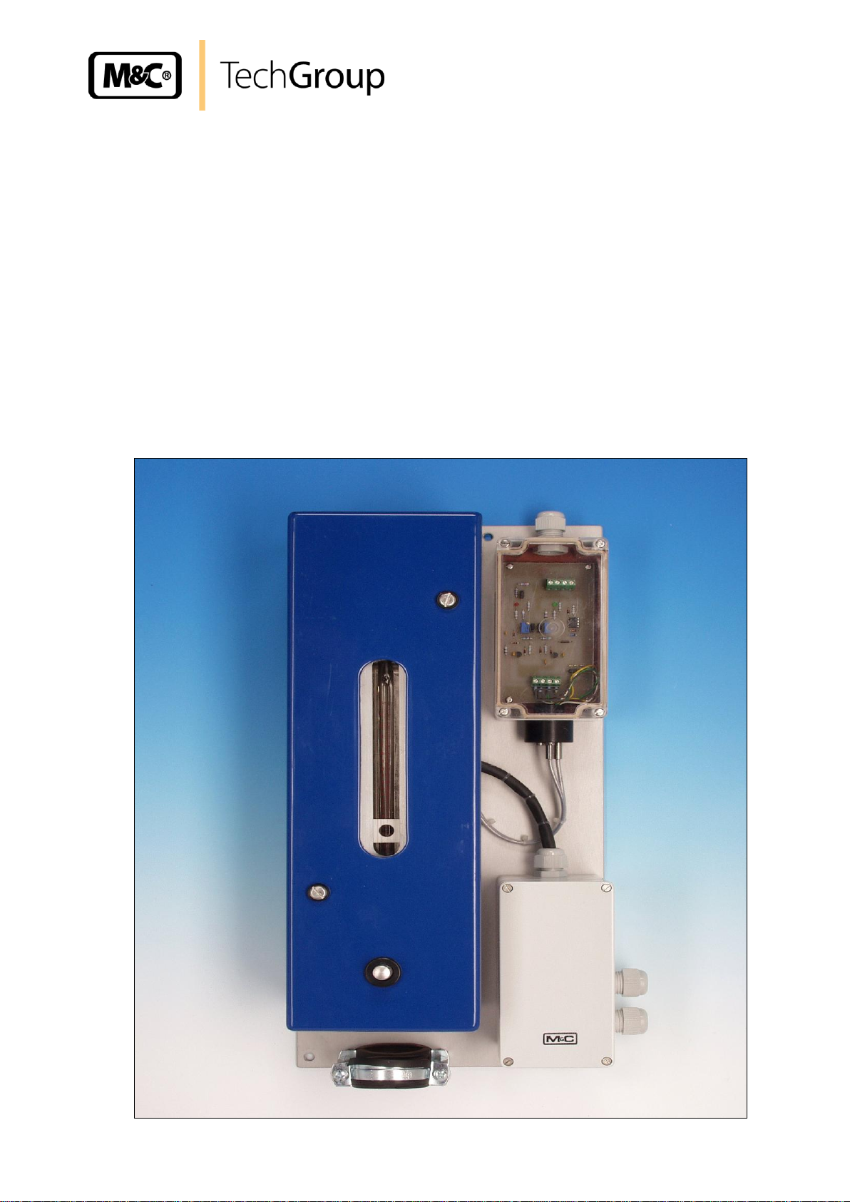
Flowmeter Series FM®
Version FM-2K, FM-200K-H, FM-200K-H/FA
Gas sampling and gas conditioning technology 5-6.5.1-ME
Page 2

2
This Operating Manual does not claim completeness and may be
subject to technical modifications.
© 03/2004 M&C TechGroup Germany GmbH. Reproduction of this
document or its content is not allowed without permission from M&C.
FM® is a registered trade mark.
1st Edition: 03/2004
Dear customer,
we have made up this operating manual in such a way that all necessary information about the
product can be found and understood quickly and easily.
Should you still have any question, please do not hesitate to contact M&C directly or go through your
appointed dealer. Respective contact addresses are to be found in the annexe to this operating
manual.
Please also contact our homepage www.mc-techgroup.com for further information about our
products. There, you can read or download the data sheets and operating manuals of all M&C
products as well as further information in German, English and French.
Gas sampling and gas conditioning technology 5-6.5.1-ME
Page 3

3
Contents
1 General information ...................................................................................................................... 4
2 Declaration of conformity ............................................................................................................ 4
3 Safety instructions ....................................................................................................................... 5
4 Warranty ........................................................................................................................................ 5
5 Used terms and signal indications ............................................................................................. 6
6 Introduction ................................................................................................................................... 7
7 Serial numbers .............................................................................................................................. 7
8 Power supply ................................................................................................................................ 7
9 Warnings and instructions .......................................................................................................... 7
10 Technical Data .............................................................................................................................. 8
11 Applications .................................................................................................................................. 9
12 Description .................................................................................................................................... 9
13 Delivery ........................................................................................................................................ 10
14 Preparation and Installation ...................................................................................................... 10
15 Mounting ...................................................................................................................................... 10
16 Electrical Connection ................................................................................................................. 11
17 Starting ........................................................................................................................................ 12
18 Maintenance ................................................................................................................................ 13
19 Spare parts list ............................................................................................................................ 14
20 Appendix ..................................................................................................................................... 14
List of illustrations
Figure 1 Flow rate in Nl/hr air and differential pressure in mbar ....................................................... 8
Figure 2 Electrical connections for FM-200K-H(/FA) ...................................................................... 12
Figure 3 Electrically heated flowmeter FM-200H/FA incl. monostable flow alarm .......................... 15
Figure 4 Electrically heated flowmeter FM-200H ............................................................................ 16
Gas sampling and gas conditioning technology 5-6.5.1-ME
Page 4

4
Head Office
M&C TechGroup Germany GmbH Rehhecke 79 40885 Ratingen Germany
Telephone: 02102 / 935 - 0
Fax: 02102 / 935 - 111
E - mail: info@mc-techgroup.com
www.mc-techgroup.com
1 GENERAL INFORMATION
The product described in this operating manual has been examined before delivery and left our works
in perfect condition related to safety regulations. In order to keep this condition and to guarantee a
safe operation, it is important to heed the notes and prescriptions made in this operating manual.
Furthermore, attention must be paid to appropriate transportation, correct storage, as well as
professional installation and maintenance work.
All necessary information a skilled staff will need for appropriate use of this product are given in this
operating manual.
2 DECLARATION OF CONFORMITY
CE - Certification
The product described in this operating manual complies with the following EC directives:
EMV-Instruction
The requirements of the EC directive 2004/108/EC “Electromagnetic compatibility“ are met.
Low Voltage Directive
The requirement of the EC directive 2006/95/EC “Low Voltage Directive“ are met.
The compliance with this EC directive has been examined according to DIN EN 61010.
Declaration of conformity
The EU Declaration of conformity can be downloaded from the M&C homepage or directly requested
from M&C.
Gas sampling and gas conditioning technology 5-6.5.1-ME
Page 5

5
3 SAFETY INSTRUCTIONS
Please take care of the following basic safety procedures when mounting, starting up or
operating this equipment:
Read this operating manual before starting up and use of the equipment. The information and
warnings given in this operating manual must be heeded.
Any work on electrical equipment is only to be carried out by trained specialists as per the regulations
currently in force.
Attention must be paid to the requirements of VDE 0100 (IEC 364) when setting high-power electrical
units with nominal voltages of up to 1000 V, together with the associated standards and stipulations.
Check the details on the type plate to ensure that the equipment is connected to the correct mains
voltage.
Protection against touching dangerously high electrical voltages:
Before opening the equipment, it must be switched off and hold no voltages. This also applies to any
external control circuits that are connected.
The device is only to be used within the permitted range of temperatures and pressures.
Check that the location is weather-protected. It should not be subject to either direct rain or moisture.
The device must not be used in hazardous areas.
Installation, maintenance, monitoring and any repairs may only be done by authorized personnel with
respect to the relevant stipulations.
4 WARRANTY
If the equipment fails, please contact M&C directly or else go through your M&C authorised dealer.
We offer a one year warranty as of the day of delivery as per our normal terms and conditions of sale,
and assuming technically correct operation of the unit. Consumables are hereby excluded. The terms
of the warranty cover repair at the factory at no cost or the replacement at no cost of the equipment
free ex user location. Reshipments must be send in a sufficient and proper protective packaging.
Gas sampling and gas conditioning technology 5-6.5.1-ME
Page 6

6
DANGER!
This means that death, severe physical injuries and/or important
material damages will occur in case the respective safety measures
are not fulfilled.
WARN I N G!
This means that death, severe physical injuries and/or important
material damages may occur in case the respective safety
measures are not fulfilled.
CARE!
This means that minor physical injuries may occur in case the
respective safety measures are not fulfilled.
CARE!
Without the warning triangle means that a material damage may
occur in case the respective safety measures are not met.
ATT E NT I ON!
This means that an unintentional situation or an unintentional status
may occur in case the respective note is not respected.
NOTE!
These are important information about the product or parts of the
operating manual which require user’s attention.
SKILLED STAFF
These are persons with necessary qualification who are familiar with
installation, use and maintenance of the product.
5 USED TERMS AND SIGNAL INDICATIONS
Gas sampling and gas conditioning technology 5-6.5.1-ME
Page 7

7
NOTE!
Always quote the device's serial number when making enquiries and
ordering replacement parts.
NOTE!
The instructions and warnings listed in the instructions for use must be
complied with!
6 INTRODUCTION
Flowmeters are used in analysis technique to control the gas flow. In dependance of the application it
could be necessary to use a heated or heatable version. Especially for this applications the M&C
flowmeters FM-2K and FM-200K-H(/FA) are designed.
7 SERIAL NUMBERS
The nameplates bearing the serial number are located on the mounting plate.
8 POWER SUPPLY
The flowmeters can be operated on alternating current in the range from 230 V, 50Hz or 115V, 60Hz.
9 WARNINGS AND INSTRUCTIONS
Gas sampling and gas conditioning technology 5-6.5.1-ME
Page 8

10 TECHNICAL DATA
Technical Data
FM-2K
FM-200K-H
FM-200K-H/FA
Part-No.
09F2105
09F2505
09F2555 **
Heated / needle valve in the
inlet
no
yes
yes
Optical flow control, mono-stable **
no
no
fix between 20 - 50%
of scale
Standard measuring range
25-250 l/hr air, 1.2 bar, 180°C
Measuring ranges available
Scale: 1.6-16, 6-60, 10-100, 25-250, 50-500, 80-800 l/hr air,
1.2 bar, 180°C
Operating pressure / operating
temperature
max. 2 bar / max. +180°C
Ambient temperature
-40 to +180°C
-25 to +60°C
-25 to +50°C
Storage temperature
-40 to +80°C
-25 to +80°C
Gas connections
¼“ NPT i
Tube fittings Swagelok ø6mm, optional ø1/4“
Temperature controller
-----------------------------
Capillary thermostat, integrated in electrical
connection box with high temperature limiter
and low temperature alarm contact
Operating temperature
-----------------------------
adjustable from 0 to 180°C, set in factory at
180°C
Temperature alarm contact
-----------------------------
alarm point T -30°C to T
Set
change over contact, voltage free; contact
rating 250V, 3A, 0,25A=
Power supply
-----------------------------
230V 50Hz, 220VA optional 115V 60Hz (a)
Electrical connections
-----------------------------
Terminals 2,5 mm², 2x Cable glands PG13
Protection / Electrical
standard
-----------------------------
IP 54 EN60529 / EN 61010, EN60519-1
Dimensions
50 x 290 x 50mm (w x
h x d)
250 x 500 x 140mm (w x h x d)
Weight
0.8 kg
8 kg
8.5 kg
Dead volume / Mounting
approx. 6 cm³ / wall mounting
Material of sample contacting parts
glass, stainless steel 316, PTFE
0
10
20
30
40
50
0 150 300 450 600 750 900 1050
Nl/hr
mbar
8
** The optical flow alarm is only equipped with pre-amplifier K-FA-H, the electronic controller must be ordered separately
.
Figure 1 Flow rate in Nl/hr air and differential pressure in mbar
Gas sampling and gas conditioning technology 5-6.5.1-ME
Page 9

9
11 APPLICATIONS
The M&C flowmeters FM-2K and FM-200K-H(/FA) are used in analysis technique to control gas flow
up to an operating temperature of 180 °C.
Depending on the flowmeter glass tube, ranges from 16 l/h to 800 l/h can be realized.
12 DESCRIPTION
The M&C flowmeters FM-2K and FM-200K-H(/FA) consist of a vertical cone shaped glass tube with a
free movable float ball inside. The sample gas, flowing from the bottom to the top, lifts the float ball as
far as an annular gap appears between the tube wall and the float ball and the forces on the ball are
compensated. The position of the float ball is related to a scale on the flow meter tube. The FM-2K is a
basic heat resistant version for installation in heated systems.
The electrically heated version FM-200K-H(/FA) is equipped with an integrated needle valve and is
fixed on a mounting plate, decoupled from heat and covered with an insulated enclosure. The heater
consists of a heating element with high capacity. The temperature is adjustable on the integrated
thermostat up to 180 °C with high temperature limiter and low temperature alarm.
The window of the heat insulated enclosure guarantees a proper reading-out.
The electrical connection box with integrated thermostat is installed outside the enclosure on the
mounting plate. A flow control is possible consisting of fibre-optical light guides FO1, the sensor head
FA2-H and the pre-amplifier K-FA-H which is installed on the mounting plate as well. The electronic
controller FA... (option) has to be mounted externally. – See data sheet 5-6.10.2. –
In order to avoid cold spots, the connecting fittings are equally heated by means of double-ended
thermal conducting jaws. The electrically heated sample lines type 3/4/5-N/M/H – see data sheet 2-6.1
– are fixed with mounting brackets.
Part numbers:
09F2105 FM-2K heatable up to 180°C
09F2505 FM-200K-H el. heated up to 180°C with needle valve
09F2555 FM-200K-H/FA heated, with needle valve and flow control
Gas sampling and gas conditioning technology 5-6.5.1-ME
Page 10

10
NOTE!
Make sure that the connection is leak proof!
13 DELIVERY
The flowmeter Series FM® is normally delivered in one packaging unit:
The flowmeter Series FM® should be removed carefully from the packaging and checked immediately
for completeness against the delivery note.
Check the goods for any damage incurred during transport and if necessary inform your transport
insurer of any damage.
14 PREPARATION AND INSTALLATION
Locate the flowmeter Series FM® in such a way that there is adequate space for removing the cover
and replacing the glass tube. Fix the aluminium plate with 4 screws.
Make certain that the flowmeter Series FM® is easily accessible so that you can carry out any
subsequent maintenance work without trouble.
15 MOUNTING
Loosen the two screws beside the window
Remove the cover of the flowmeter
Disconnect the thermal conductivity jaws on the bottom of the flowmeter in two parts by
loosening the screws, two each
Connect the sample lines at the fittings
assemble the two thermal conductivity jaws on the bottom once again
Put the cover of the flowmeter on top and screw it
Gas sampling and gas conditioning technology 5-6.5.1-ME
Page 11

11
WARN I N G!
When connecting the equipment, please ensure that the supply
voltage is identical with the information provided on the model type
plate.
NOTE!
Attention must be paid to the requirements of IEC 364 (DIN VDE
0100) when setting high-power electrical units with nominal
voltages of up to 1000 V, together with the associated standards
and stipulations.
A main switch and matching fuse must be provided externally!
The main circuit must be equipped with a fuse corresponding to
the nominal current (over current protection), for electrical details
see technical data.
16 ELECTRICAL CONNECTION
Remove the lid of the electrical connection box. The electrical connection layout is located in
the lid.
Insert the mains cable (min. 3 x 1.5 mm²) through the cable gland and connect to the
appropriate terminals.
Insert the signal cable through the cable gland and connect to the appropriate terminals.
Screw lid back on.
Gas sampling and gas conditioning technology 5-6.5.1-ME
Page 12

12
Figure 2 Electrical connections for FM-200K-H(/FA)
17 STARTING
Before starting up check whether the mains power supply voltage corresponds with the
information stated on the type plate.
Switch on mains power supply.
The total heating-up time is approximately 30 min. The flowmeter then is ready for operation
Gas sampling and gas conditioning technology 5-6.5.1-ME
Page 13

13
NOTE!
The safety instructions specific to the plant and process are to be
consulted prior to any maintenance work!
WARN I N G!
Aggressive condensate is .
Wear protective glasses and proper protective clothing!
High surface temperatures! Wear protective gloves!
NOTE!
Prior to carrying out maintenance work on electrical parts, mains
voltage should be disconnected from all poles!
This also applies to any external control circuits, which may be
connected.
18 MAINTENANCE
It is difficult to give any recommendations as to a particular maintenance cycle. Depending on your
process conditions, a meaningful maintenance cycle must be elaborated for the specific application.
Check from time to time, if the flowmeter glass is soiled.
To clean the flowmeter glass remove cover lid.
Unscrew the aluminium lid.
Disconnect the thermal conductivity jaws on the top and at the bottom of the flowmeter in two
parts by loosening the screws, two each.
Disconnect the 2 sample lines.
Disconnect the tube at the top of the flowmeter.
Take out the flowmeter including needle valve.
Loosen the 3 hexagon screws on the upper and lower adapter, until you can pull them out.
Pull out the glass, check and clean it.
Check O-rings on top and bottom and change if necessary.
Assemble the flowmeter in reverse sequence.
Gas sampling and gas conditioning technology 5-6.5.1-ME
Page 14

14
Flowmeter Series FM®
((C) Consumable parts
(R) Recommended spare parts
(S) Spare parts
Recommended quantity being in
operation [years]
Part No.
Indication
C/R/S
1 2 3
91 F 1040
Spare o-ring set for flowmeter FM..-HT 2 pcs.
PTFE spiral o-rings
type MAA 612-01-05-1
R 1 1
2
90 S 2042
O-ring (11) for and FM-2K, FM-200K/H
Material: Viton.
R 1 1
2
91 F 2000
Cartridge heater HLPSR, 100mm, 230VAC/220W
R 1 1 1 91 F 2000a
Cartridge heater HLPSR, 100mm, 115VAC/200W
R 1 1 1 90 P 5020
Thermostat (0-180°C) for FT-…-H2
R 1 1
1
19 SPARE PARTS LIST
Wear, tear and replacement part requirements depend on specific operating conditions.
The recommended quantities are based on experience and they are not binding.
20 APPENDIX
Heated Flowmeter FM200-H/FA
Drawing No. : 22491021
Heated Flowmeter FM200-H
Drawing No.. : 22491011
Further product documentation can be seen and downloaded from our home page:
www.mc-techgroup.com
Gas sampling and gas conditioning technology 5-6.5.1-ME
Page 15

15
Figure 3 Electrically heated flowmeter FM-200H/FA incl. monostable flow alarm
Gas sampling and gas conditioning technology 5-6.5.1-ME
Page 16

16
Figure 4 Electrically heated flowmeter FM-200H
Gas sampling and gas conditioning technology 5-6.5.1-ME
 Loading...