

Page 1
Operating Manual
Optical flow alarm FA1-H
Gas sampling and gas conditioning technology 5-6.15ME
Page 2

2
List of Contents
1 General information .................................................................................................................. 4
2 Declaration of conformity ........................................................................................................ 4
3 Safety instructions .................................................................................................................... 5
4 Warranty .................................................................................................................................... 5
5 Used terms and signal indications .......................................................................................... 6
6 Introduction ............................................................................................................................... 7
7 Application ................................................................................................................................ 7
8 Technical Data ........................................................................................................................... 7
8.1 Options .................................................................................................................................... 8
9 Description ................................................................................................................................ 9
10 Receipt of marchendise and storage .................................................................................... 10
11 Mounting .................................................................................................................................. 10
12 Electrical connections ............................................................................................................ 11
13 Starting .................................................................................................................................... 13
13.1 Alignment of the delay time ................................................................................................... 13
13.2 Alignment of the sensitivity .................................................................................................... 13
14 Maintenance ............................................................................................................................ 14
15 Annexe ..................................................................................................................................... 14
List of Illustrations
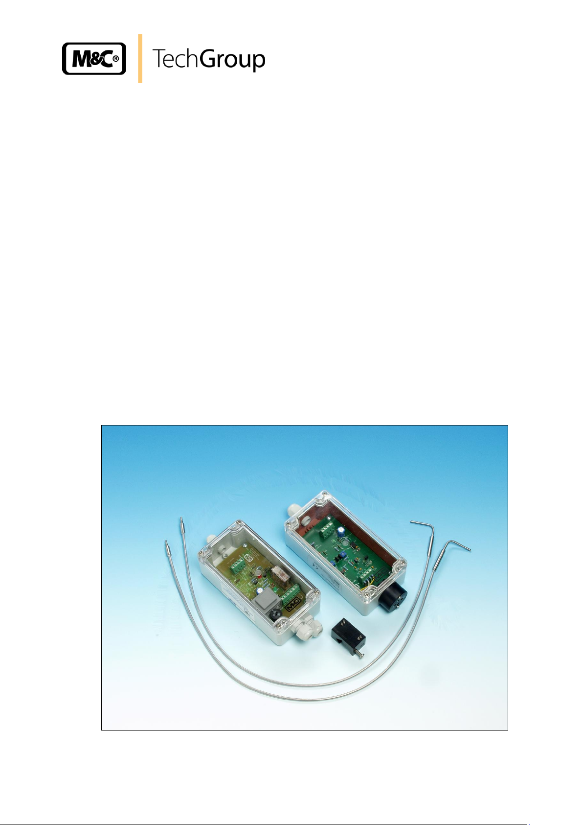
Figure 1 Complete optical flow monitoring system .......................................................................... 9
Figure 2 Electrical connection of the pre-amplifier K-FA-H ............................................................ 12
Figure 3 Electrical connection FA1-H ............................................................................................ 12
Figure 4 Circuit diagram of electronic K-FA-H 115/230V ............................................................... 15
Gas sampling and gas conditioning technology 5-6.15ME
Page 3

3
This Operating Manual does not claim completeness and may be
subject to technical modifications.
© 05/2005 M&C TechGroup Germany GmbH. Reproduction of this
document or its content is not allowed without permission from M&C.
FA® is a registered trade mark.
2nd Edition: 09/2009
Dear customer,
we have made up this operating manual in such a way that all necessary information about the
product can be found and understood quickly and easily.
Should you still have any question, please do not hesitate to contact M&C directly or go through your
appointed dealer. Respective contact addresses are to be found in the annexe to this operating
manual.
Please also contact our homepage www.mc-techgroup.com for further information about our
products. There, you can read or download the data sheets and operating manuals of all M&C
products as well as further information in German, English and French.
Gas sampling and gas conditioning technology 5-6.15ME
Page 4

4
Head Office
M&C TechGroup Germany GmbH Rehhecke 79 40885 Ratingen Germany
Telephone: 02102 / 935 - 0
Fax: 02102 / 935 - 111
E - mail: info@mc-techgroup.com
www.mc-techgroup.com
1 GENERAL INFORMATION
The product described in this operating manual has been examined before delivery and left our works
in perfect condition related to safety regulations. In order to keep this condition and to guarantee a
safe operation, it is important to heed the notes and prescriptions made in this operating manual.
Furthermore, attention must be paid to appropriate transportation, correct storage, as well as
professional installation and maintenance work.
All necessary information a skilled staff will need for appropriate use of this product are given in this
operating manual.
2 DECLARATION OF CONFORMITY
CE - Certification
The product described in this operating manual complies with the following EC directives:
EMV-Instruction
The requirements of the EC directive 2004/108/EC “Electromagnetic compatibility“ are met.
Low Voltage Directive
The requirement of the EC directive 2006/95/EC “Low Voltage Directive“ are met.
The compliance with this EC directive has been examined according to DIN EN 61010.
Declaration of conformity
The EU Declaration of conformity can be downloaded from the M&C homepage or directly requested
from M&C.
Gas sampling and gas conditioning technology 5-6.15ME
Page 5

5
3 SAFETY INSTRUCTIONS
Please take care of the following basic safety procedures when mounting, starting up or
operating this equipment:
Read this operating manual before starting up and use of the equipment. The information and
warnings given in this operating manual must be heeded.
Any work on electrical equipment is only to be carried out by trained specialists as per the regulations
currently in force.
Attention must be paid to the requirements of VDE 0100 (IEC 364) when setting high-power electrical
units with nominal voltages of up to 1000 V, together with the associated standards and stipulations.
Check the details on the type plate to ensure that the equipment is connected to the correct mains
voltage.
Protection against touching dangerously high electrical voltages:
Before opening the equipment, it must be switched off and hold no voltages. This also applies to any
external control circuits that are connected.
The device is only to be used within the permitted range of temperatures and pressures.
Check that the location is weather-protected. It should not be subject to either direct rain or moisture.
The device must not be used in hazardous areas.
Installation, maintenance, monitoring and any repairs may only be done by authorized personnel with
respect to the relevant stipulations.
4 WARRANTY
If the equipment fails, please contact M&C directly or else go through your M&C authorised dealer.
We offer a one year warranty as of the day of delivery as per our normal terms and conditions of sale,
and assuming technically correct operation of the unit. Consumables are hereby excluded. The terms
of the warranty cover repair at the factory at no cost or the replacement at no cost of the equipment
free ex user location. Reshipments must be send in a sufficient and proper protective packaging.
Gas sampling and gas conditioning technology 5-6.15ME
Page 6

6
DANGER!
This means that death, severe physical injuries and/or important
material damages will occur in case the respective safety
measures are not fulfilled.
WAR N IN G!
This means that death, severe physical injuries and/or important
material damages may occur in case the respective safety
measures are not fulfilled.
CARE!
This means that minor physical injuries may occur in case the
respective safety measures are not fulfilled.
CA R E!
Without the warning triangle means that a material damage may
occur in case the respective safety measures are not met.
AT T EN TI O N!
This means that an unintentional situation or an unintentional
status may occur in case the respective note is not respected.
NOTE!
These are important information about the product or parts of the
operating manual which require user’s attention.
SKILLED STAFF
These are persons with necessary qualification who are familiar
with installation, use and maintenance of the product.
5 USED TERMS AND SIGNAL INDICATIONS
Gas sampling and gas conditioning technology 5-6.15ME
Page 7

7
Sensor Head
FA2-H
Light guide
FO1
Light guide
FO3
Light guide
FO2
pre-amplifier
K-FA-H
Part Number
02 E 4002
02 E 4060
02 E 4063
02 E 4065
02 E 4010
Function
monostable
1x
2x
1x
Measuring tube
5-14 mm
Light guide length
600 mm
900 mm
1200 mm
Dimensions
W x D x H
24 x 40 x 24
ø 6 mm
80 x 160 x 55
Weight
90 g
230 g
330 g
420 g
560 g
Material
anodized
aluminium
glass fibre, SS 316Ti, brass-chromed
Polycarbonate
combustibility
class
VO (UL94)
Assembly
Fixed with clamping screw
Wall mounting
Cable entry
terminal range
5mm - 10mm
Electrical
connection
terminals
2,5mm2
Supply voltage
12V DC internal
from FA-1..
Electrical standard
EN 61010
Operating
temperature
- 25°C to + 180°C
-25°C to + 60°C
Storage
temperature
- 25°C to + 70°C
System of
protection
IP65 EN 60529
6 INTRODUCTION
Optical flow monitoring systems are used for contiuous gas analysis with corrosive sample gases, to
have the possibility of using flowmeters with corrosion resistant floating balls out of e.g. glass.
The optical flow monitoring systems FA1-H-.. are an alternative to the optical flow monitoring systems
FA-1 with light fork barrier. These units can be used in heated gas conditioning systems up to 180°C
also with non metallic or very small floating balls.
7 APPLICATION
The optical flow monitoring unit with light guides is used in gas analysis on heated flowmeters with
temperatures > 60 °C. The measuring cones must be transparent. Thanks to optical scanning, very
low flow quantities can be recorded even in case of flowmeters with non-metallic or very small (1 mm)
floats.
8 TECHNICAL DATA
Gas sampling and gas conditioning technology 5-6.15ME
Page 8

8
Electronic controller
FA-1.1
FA-1.4
Part No. 230V 50/60Hz
02 E 7300*
02 E 7110
Part No. 115V 50/60Hz
02 E 7300*
02 E 7110 a
Part No. 24V DC
02 E 7300 d
02 E 7110 d
Part No. 24V AC
02 E 7300 b
02 E 7110 d
Complete flow monitoring unit
Type
Part No.
FA1-H-6
02 E 4270
FA1-H-9
02 E 4273
FA1-H-12
02 E 4275
consisting of :
Sensor FA2-H
(02 E 4002)
1 piece
Light guide FO1, 600 mm long
(02 E 4060)
2 pieces
Light guide FO3, 900 mm long
(02 E 4063)
2 pieces
Light guide FO2, 1200 mm long
(02 E 4065)
2 pieces
Pre-amplifier with adapter K-FA-H
(02 E 4010)
1 piece
Electronic controller FA-1.1 / 230V/115V
(02 E 7300)
1 piece
8.1 OPTIONS
Separate electronic controller required for the K-FA-H pre-amplifier:
Complete flow monitoring unit FA1-H-.. :
Gas sampling and gas conditioning technology 5-6.15ME
Page 9

9
9 DESCRIPTION
The M&C flow monitoring unit FA1-H-.. consists of 4 sub-assembly modules:
1. the patented sensor head FA2-H,
2. the 2 light guides FO.. for monostable function
3. the K-FA-H pre-amplifier
4. the electronic controller FA-1.1 or FA-1.4 (see data sheet FA-.., K-FA 5-6.10.2)
Figure 1 Complete optical flow monitoring system
The sensor head FA2-H is assembled on e.g. the FM1-H flowmeter by means of a pressure screw
with its stationary open prism to the measuring glass. Assembly is simple and does not require any
disassembly of the flow-measuring glass.
The FO1 light guide is supplied with a standard length of 600 mm. Light guide FO3 (900 mm long) and
FO2 (1200 mm long) can be supplied for greater length requirements. The angled light-guide ends are
fixed into the FA2-H sensor head with one pressure screw each. Two light-guides are needed for the
monostable function. By use of the pre-amplifier K-FA-H a distance of 200 meters between the flow
meter and the electronic controller FA-1.. (see data sheet 5-6.10.2) is possible without problems.
The LED emitters' light beam passes through the FO .. light guides and falls upon the photo-transistor
through e.g. the FM1-H flowmeter measuring glass. As soon as the float breaks the light beam, the
photo-transistor is blacked out. The FA-1.. electronic controller analyses this changed status
accordingly. By the monostable version a MIN alarm function in the lowest sensor setting position is
guaranteed.
Gas sampling and gas conditioning technology 5-6.15ME
Page 10

10
NOTE!
The optical flow monitoring system should be stored in a protected frost-free
area !
CA R E!
Never screw down the stainless steel pressing screw without the white
coloured protecting cap! It should always be only hand-screwed!
CA R E!
The metallic protective covering of the spiral hose of the light guides must
not be bended to tight, the minimum bending radius is 25 mm.
10 RECEIPT OF MARCHENDISE AND STORAGE
The optical flow monitoring system is delivered in 4 sub-assembly modules :
sensor head FA2-H,
2 light guides FO..
K-FA-H pre-amplifier
electronic controller FA-1.1 or FA-1.4.
Please take the optical flow monitoring system and possible special accessories carefully out of the
packaging material immediately after arrival, and compare the goods with the items listed on the
delivery note;
Check the goods for any damage caused during delivery and, if necessary, notify your transport
insurance company without delay of any damage discovered.
11 MOUNTING
The mono-stable version has got 2 light guides FO1/2/3 which must be mounted according to drawing
inside the sensor head FA2-H and inside the connection adaptor OA-bi in opposite position 2 + 1.
Inside the connection adaptor, there are always 2 high capacity LED's as light source and 2 photo
transistors as receiver which are mechanically protected.
In case of mono-stable function, only 1 piece each is used and the way 4 + 3 are shut with screws
M4x8 in the works in order to avoid optical interferences.
The sensor head FA2-H has to be fixed to the desired control point of the flow sensor
measuring tube with the pressing screw showing to the right side. It has to be fixed in such a
way that the light ray of the flow alarm sensor should not be deflected by an eventual
inscription or coloured background of the measuring tube.
The light guides type FO1 have got a total length of 600 mm, type FO2 has got a length of
1200 mm and type FO3 has got a length of 900 mm. They have to be lead with their inserted
ends from inside to outside via a cable gland or similar in the heat isolated wall of a heated
housing. Attention must be paid that the angled 3mm light guide ends in the positioned sensor
head FA2-H can be mounted without pulling. The fixing of the light guides by a cable gland or
similar can only be effected after the mounting has been finished because in the next mounting
step they have to be screwed into the adapter OA-bi.
Gas sampling and gas conditioning technology 5-6.15ME
Page 11

11
NOTE!
In case the light guide ends cannot be pushed deep enough, the fastening
screws in the front side of the sensor head must be unscrewed accordingly
by turning left-hand.
CA R E!
Fasten the light guide ends only fingertight.
NOTE!
The conception of the forked light barrier guaranties a problem-free function
in normal day light or normal ambient light. A strong light from outside to the
sensor must, however, be avoided.
WAR N IN G!
False supply voltage can damage the equipment. When connecting
the equipment, please ensure that the supply voltage is identical
with the information provided on the model type plate!
NOTE!
For the assembly of power installations with rated voltages up to
1000V, the requirements of VDE 0100 and relevant standards and
specifications must be observed!
The main circuit is equipped with a fuse corresponding to the
nominal current (over current protection); for electrical details see
technical data (chapter 8 and manual 5-6.10ME).
First of all, the 2 light guide ends have to be mounted according to their marking (1+2). They
are mounted with their metal screwing ends in the connection adapter OA-bi which is situated
in the housing wall of the pre-amplifier K-FA-H for mounting in "cold area" by turning right-hand
until limit stop.
Push one angled light guide end according to the marking (2) into the location hole on the left
side of the sensor head FA2-H. Push them as far as they touch the measuring glass of the
flowmeter e.g. FM1-H.
Push the other angled light guide according to the marking (1) as far as possible into the
location hole on the right side of the sensor head FA2-H so that the light guide ends touch the
measuring glass of the flowmeter.
The light guide ends are fixed in the sensor head with one fastening screw each by turning
right-hand.
Mount the pre-amplifier K-FA-H and electronic controller FA1-... A distance of 200 meters
between pre-amplifier and electronic controller is no problem.
12 ELECTRICAL CONNECTIONS
Gas sampling and gas conditioning technology 5-6.15ME
Page 12

12
8 7 6
5
17
16
15
1 2 3
14
11
12
L N P
br
ws
ge
br
ws
ge
FA-K-H
FA1.1
and
FA1.4
NC
For the electrical connection, the following steps have to be carried out (see also figure 2+3):
Loosen the 4 lid screws and remove the lid of pre-amplifier K-FA-H.
Lead the connection cable through the respective clamping screw.
The electronic controller FA-1.. has to be connected on clamping block X1, terminals 5 =
yellow, 7 = white and 8 = brown.
Further electrical connection of the electronic controller FA-1.. is described in manual 5-6.10ME,
chapter 13.
Figure 2 Electrical connection of the pre-amplifier K-FA-H
Figure 3 Electrical connection FA1-H
Gas sampling and gas conditioning technology 5-6.15ME
Page 13

13
WAR N IN G!
False supply voltage can damage the equipment. When connecting
the equipment, please ensure that the supply voltage is identical
with the information provided on the model type plate!
13 STARTING
Check the correct constellation of the equipment (Fig.1).
Without gas charging, the floating ball in the flowmeter is in down position. In case of mono-
stable function, the sensor head is mounted on the measuring tube in such a way that the
floating ball is placed in its deepest possible position inside the sensor head and darkens the
light ray of the sensor. The MIN-point can be lifted by placing a limit stop for the floating ball
inside the flowmeter.
Switch on the power supply for the electronic controller. According to the set retardation of
time, the red LED of the electronic controller FA-1.. is beaming - alarm situation.
Bring the floating ball by feeding of gas through the light ray of the flow alarm sensor from the
down position to a position above the sensor head.
According to the set retardation of time (s. 13.1), the green LED of the electronic controller is
beaming - O.K. situation. On the pre-amplifier K-FA-H with mono-stable function, the red LED
is beaming in O.K. situation, the green LED has no function and is always beaming.
The flow monitoring system is ready for operation now.
13.1 ALIGNMENT OF THE DELAY TIME
Unintentional alarms in case of pulsating gas flow can be avoided by this function.
Slow operation: The cutoff of the alarm is delayed (ex works 3 sec.).
Slow release: The alarm release is delayed (ex works 2 sec.).
The alignment of the delay time is described in manual 5-6.10ME, chapter 14.3.
13.2 ALIGNMENT OF THE SENSITIVITY
If in case of alarm no alarm message is set off, an incorrect adjusted sensitivity could be the reason.
In case a complete control system consisting of sensor, light guides, pre-amplifier, electronic control
and flowmeter is ordered, the alignment is made at works. In case the client orders single components
for assembling and the alarm function does not work with other measuring glasses, the adaptation can
be effected.
The alignment of the sensitivity is described in manual 5-6.10ME, chapter 14.2.
Gas sampling and gas conditioning technology 5-6.15ME
Page 14

14
NOTE!
Before carrying out any maintenance or repair work, the specific safety
procedures pertaining to the system and the operational process have to
be observed!
14 MAINTENANCE
The flow control units series FA® are functioning without necessity of maintenance over a long time. It
may be that the LED and the phototransistors of the flow alarm sensor FA-2H must be cleaned due to
dust deposits.
Please execute this cleaning with a dry cotton bud (Q-tip). If you want to humid this cotton bud, do only
use water !
In case the measuring glass of the flowmeter if dirty, it must be cleaned so that the necessary light
transmission is granted.
If there is any defect on the electronics, please return the device for repair to M&C.
15 ANNEXE
Circuit diagram K-FA-H
For further product documentation, please see our internet catalogue:
www.mc-techgroup.com
Operating manual flow alarm sensors and electronic controllers series FA®, 5-6.10ME
Gas sampling and gas conditioning technology 5-6.15ME
Page 15

15
Figure 4 Circuit diagram of electronic K-FA-H 115/230V
Gas sampling and gas conditioning technology 5-6.15ME
 Loading...