

Page 1

FA1.1, FA1.4
Embracing Challenge
Electronic controller series FA®
Versions FA-1.1, FA-1.4, K-FA
for ow monitoring sensors series FA® and for liquid alarm
sensor series KS®, version KS 2
Special Features
For wall or rail mounting
3 operating modes
Line break monitoring
Alarm contact with „safety-rst“
switching and pull-in and drop-o time
lag
LED’s for displaying operational and
fault status
Automatically controlled luminosity of
the ow-monitoring sensor FA®
Application
The M&C electronic controllers series FA®
are required for the operation of the flowmonitoring sensors FA-1/2/3bi and FA1-H
(see 5-6.15) as well as the liquid sensor KS2
(not KS 2.Ex).
Description
The M&C electronic controllers series FA® are
available in two types of housings for wallmounting or rail-mounting.
Each of these types includes three operating
modes determined by the electrical connection:
• Electronic controller for flow-monitoring
in bi-stable execution in combination
with the flow alarm sensors FA-1/2/3bi.
• Electronic controller for flow-monitoring in mono-stable execution in combination with the flow alarm sensors
FA-1/2/3bi or FA2-H.
Additionally, the luminosity of the flow-monitoring sensor FA.. is automatically controlled
in dependence on the ambient and operating conditions (lighting conditions, temperature, aging of the LED’s, contamination of the
flowmeter glass, ...).
In case of operating a bi-stable flow monitoring, the identification of the set flow rate
value adjusted by the optical flow alarm
sensor FA.. in the event of exceeding or falling below the present value (MIN or MAX) is
guaranteed .
In case of mono-stable operation, a statement
is only given whether the float is located in
the light beam of the optical flow alarm sensor FA.. , or above it or below it.
Technical specications and illustrations are without
obligation, subject to modications. 10.99/06.06
• Electronic controller for liquid sensor KS
2 or operation in combination with the
external pre-amplifiers K-FA and K-FA-H
(see 5-6.15) if the wiring length between
the flow alarm sensor FA.. and the electronic FA-1.. is more than 10 meters or if
strong stray electrical signals influence
the evaluation via the sensor cable.
For sure operation a line break monitoring
is integrated and for sure alarm signalling a
potential-free change-over contact with “safety-first“ switching is existing. In order to avoid
unwanted alarm signals in case of pulsating
gas flow, the alarm switch has a pull-in and
drop-off time-lag. For displaying operational
and fault status there are two LED’s.
The FA-1.. electronic controllers are balanced
in the factory for the sensors FA.. and the
measuring glass of the FM-1/10/40 flowmeter.
M&C TechGroup Germany GmbH • Rehhecke 79 • 40885 Ratingen • Germany
info@mc-techgroup.com • www.mc-techgroup.com • Fon +49 2102 935-0 • Fax +49 2102 935-111
9.5
Page 2
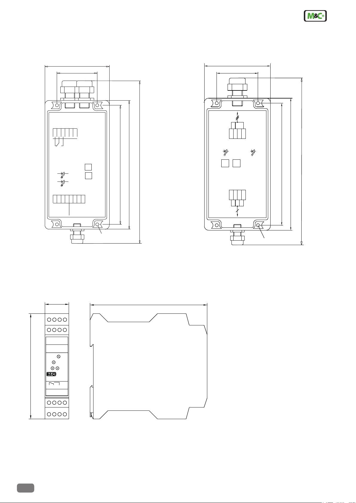
Dimensions
80
FA-1.1 in wall-mounting housing
50
3
2
1
11
12
14
P E N L
Alarm
o.k.
T
gn
D3
D5
6
7
5
wh
ye
gn
Sensor FA..
P1
rd
8
16
18
15
17
ye
wh
bn
bn
gn
Sensor KS 2/K-FA(-H)
148
160
210
Pre-amplifier K-FA
X1
D15
rd
P1
X2
80
50
FA-1..
wh
bn
8
D14
P2
0V
bnwhgn
8
6
7
Sensor FA..
ye
5ye7
gn
148
160
210
5
FA-1.4 rail mounting housing
22.8
15 16
17 18
Sensor: K...
ye. gn. wh. bn.
5 6
7 8
Sensor: FA...
ye. gn. wh. bn.
Balance
adj.
Control
100
Bal.
OK.
Flowalarm FA1.4
Durchussalarm
1211 14 NC
L/+ N/- PE PE
2 3
1
Alarm
4
Ø 4,3
Ø 4,3
111
Dimensions in mm
9.5
M&C TechGroup Germany GmbH • Rehhecke 79 • 40885 Ratingen • Germany
info@mc-techgroup.com • www.mc-techgroup.com • Fon +49 2102 935-0 • Fax +49 2102 935-111
Technical specications and illustrations are without
obligation, subject to modications. 09.96/11.06
Page 3

Technical Data
Electronic controller type FA-1.1 FA1.4 K-FA **
Part No.
230V 50/60Hz
115V 50/60Hz
24V DC
24V AC
02 E 7300*
02 E 7300*
02 E 7300 d
02 E 7300 b
02 E 7110
02 E 7110 a
02 E 7110 d
02 E 7110 d
Mounting Wall mounting housing Rail mounting housing
EN 50022
Sensor inlets 1
Function mono-stable / bi-stable / KS 2 all, selectable by assignment mono- or bi-stable selectable
Power consumption 2 VA 1 VA
Alarm-relay (MC/NC/NO)
contact rating
Pull-in/drop-off time lag
250V DC/AC
AC=500VA, DC=50W, 3A
2 sec.
250V AC/DC
AC=500VA, DC=45W, 2A
of alarm relay
Cable entry 1x clamping range 3mm - 6,5mm
2x clamping range 5mm - 10mm
Electrical connections Terminals max. 2,5 mm
Adjustment of sensitivity for
sensor FA..
Distance between sensor
after removing the lid
at the potentiometer
max. 10m >10m, max. 200m
2
in the front side of the housing at
the potentiometer
and electronic FA-..
Line break monitoring yes
Housing protection type IP65 EN 60529 IP20 EN 60529 IP65 EN 60529 IP20
Housing material Polycarbonate Polyamide Polycarbonate
Ambient temperature -25 °C to +60 °C
Electrical standard EN61010
Dimensions B 80 x L 160 x H 55 mm B 22,8 x L 100 x T 111 B 80 x L 160 x H 55 mm
Weight 0,31 kg 0,18 kg 0,3 kg
* Reversing power consumption 230V 50/60Hz / 115V 50/60Hz, adjusted at works: 230V 50/60Hz
** For use in combination with electronic controller FA-1.1 or FA-1.4 if the wiring length between the ow alarm sensor and the electronic controller is more
than 10m
02 E 4020
Wall mounting housing
1x clamping range 3mm - 6,5mm
2x clamping range 5mm - 10mm
Technical specications and illustrations are without
obligation, subject to modications. 09.96/11.06
M&C TechGroup Germany GmbH • Rehhecke 79 • 40885 Ratingen • Germany
info@mc-techgroup.com • www.mc-techgroup.com • Fon +49 2102 935-0 • Fax +49 2102 935-111
9.5
 Loading...