

Page 1
Operating Manual
Electric gas cooler series EC ®
Version EC/ECS (from model nos.: 95...)
Gas sampling and gas conditioning technology 3-4.1-ME
Page 2

2
List of Contents
1 General information ................................................................................................................... 5
2 Declaration of conformity .......................................................................................................... 5
3 Safety instructions ..................................................................................................................... 6
4 Warranty ...................................................................................................................................... 6
5 Used terms and signal indications ........................................................................................... 7
6 Introduction ................................................................................................................................ 8
7 Application .................................................................................................................................. 8
8 Technical data ............................................................................................................................ 9
9 Description................................................................................................................................ 10
10 Function .................................................................................................................................... 12
11 Reception and storage ............................................................................................................. 13
12 Installation instructions ........................................................................................................... 13
13 Supply connections ................................................................................................................. 14
13.1 Hose connections ............................................................................................................. 14
13.2 Electrical connections ....................................................................................................... 15
14 Start-up ..................................................................................................................................... 17
14.1 Function sequence and LED function display ................................................................... 18
15 Closing down ............................................................................................................................ 19
16 Maintenance.............................................................................................................................. 19
16.1 Change of the filter element at option EC-F or EC-FD ..................................................... 19
16.2 Adding and replacing the heat exchangers ....................................................................... 20
16.3 Maintenance of the optional mounted peristaltic pump(s), type SR25 .............................. 20
16.3.1 Change of the pump tube ........................................................................................... 21
16.3.2 Change of contact pulleys and springs ....................................................................... 22
16.3.3 Cleaning the pump head ............................................................................................ 22
17 Trouble shooting ...................................................................................................................... 23
18 EC automatic control board .................................................................................................... 25
18.1 Connecting the cooling compressor .................................................................................. 26
18.2 Temperature setting for the EC/ECS cooler ..................................................................... 27
18.3 Connection of an external temperature reading with option second PT100 sensor
(part no. 02k9500) ............................................................................................................. 27
19 Checking the temperature sensor .......................................................................................... 28
20 Changing the cooler aggregate .............................................................................................. 29
21 Retrofitting a digital temperature indication .......................................................................... 31
21.1 Data for mounting ............................................................................................................. 31
21.2 Installation instructions ...................................................................................................... 31
21.3 Electrical connections ....................................................................................................... 32
22 Spare parts list ......................................................................................................................... 33
23 Appendix ................................................................................................................................... 34
Gas sampling and gas conditioning technology 3-4.1-ME
Page 3

3
List of Illustrations
Figure 1 Example of application of EC/ECS .................................................................................... 8
Figure 2 EC/ECS with options EC-F and EC-FD ........................................................................... 10
Figure 3 Peristaltic pump SR25.2 mounted into the front panel .................................................... 11
Figure 4 Schematic diagram of functioning of heat exchanger ...................................................... 12
Figure 5 Electrical sockets ............................................................................................................. 16
Figure 6 Pin configuration from model nos. 96... ........................................................................... 16
Figure 7 Pin configuration for EC/ECS up to model nos. 95... ....................................................... 17
Figure 8 Change of the pump tube ................................................................................................ 21
Figure 9 EC automatic control board ............................................................................................. 25
Figure 10 Connection diagram for compressor ................................................................................ 26
Figure 11 Voltage in relation to the temperature of the cooling stage ............................................. 28
Figure 12 Resistance-temperature characteristics of the PT100 temperature sensor ..................... 28
Figure 13 EC cooler aggregate ........................................................................................................ 29
Figure 14 Locating distance of digital temperature indication .......................................................... 31
Figure 15 Sample outlet dew point .................................................................................................. 35
Figure 16 Circuit diagram EC automatic control board .................................................................... 36
Figure 17 Wiring plan automatic condensate removal unit EC-FD .................................................. 37
Gas sampling and gas conditioning technology 3-4.1-ME
Page 4

4
This Operating Manual does not claim completeness and may be
subject to technical modifications.
© 05/2002 M&C TechGroup Germany GmbH. Reproduction of this
document or its content is not allowed without permission from M&C.
EC® is a registered trade mark.
2nd Edition: 08/2009
Dear customer,
we have made up this operating manual in such a way that all necessary information about the
product can be found and understood quickly and easily.
Should you still have any question, please do not hesitate to contact M&C directly or go through your
appointed dealer. Respective contact addresses are to be found in the annexe to this operating
manual.
Please also contact our homepage www.mc-techgroup.com for further information about our
products. There, you can read or download the data sheets and operating manuals of all M&C
products as well as further information in German, English and French.
Gas sampling and gas conditioning technology 3-4.1-ME
Page 5

5
Head Office
M&C TechGroup Germany GmbH Rehhecke 79 40885 Ratingen Germany
Telephone: 02102 / 935 - 0
Fax: 02102 / 935 - 111
E - mail: info@mc-techgroup.com
www.mc-techgroup.com
1 GENERAL INFORMATION
The product described in this operating manual has been examined before delivery and left our works
in perfect condition related to safety regulations. In order to keep this condition and to guarantee a
safe operation, it is important to heed the notes and prescriptions made in this operating manual.
Furthermore, attention must be paid to appropriate transportation, correct storage, as well as
professional installation and maintenance work.
All necessary information a skilled staff will need for appropriate use of this product are given in this
operating manual.
2 DECLARATION OF CONFORMITY
CE - Certification
The product described in this operating manual complies with the following EC directives:
EMV-Instruction
The requirements of the EC directive 2004/108/EC “Electromagnetic compatibility“ are met.
Low Voltage Directive
The requirement of the EC directive 2006/95/EC “Low Voltage Directive“ are met.
The compliance with this EC directive has been examined according to DIN EN 61010.
Declaration of conformity
The EU Declaration of conformity can be downloaded from the M&C homepage or directly requested
from M&C.
Gas sampling and gas conditioning technology 3-4.1-ME
Page 6

6
3 SAFETY INSTRUCTIONS
Please take care of the following basic safety procedures when mounting, starting up or
operating this equipment:
Read this operating manual before starting up and use of the equipment. The information and
warnings given in this operating manual must be heeded.
Any work on electrical equipment is only to be carried out by trained specialists as per the regulations
currently in force.
Attention must be paid to the requirements of VDE 0100 (IEC 364) when setting high-power electrical
units with nominal voltages of up to 1000 V, together with the associated standards and stipulations.
Check the details on the type plate to ensure that the equipment is connected to the correct mains
voltage.
Protection against touching dangerously high electrical voltages:
Before opening the equipment, it must be switched off and hold no voltages. This also applies to any
external control circuits that are connected.
The device is only to be used within the permitted range of temperatures and pressures.
Check that the location is weather-protected. It should not be subject to either direct rain or moisture.
The device must not be used in hazardous areas.
Installation, maintenance, monitoring and any repairs may only be done by authorized personnel with
respect to the relevant stipulations.
4 WARRANTY
If the equipment fails, please contact M&C directly or else go through your M&C authorised dealer.
We offer a one year warranty as of the day of delivery as per our normal terms and conditions of sale,
and assuming technically correct operation of the unit. Consumables are hereby excluded. The terms
of the warranty cover repair at the factory at no cost or the replacement at no cost of the equipment
free ex user location. Reshipments must be send in a sufficient and proper protective packaging.
Gas sampling and gas conditioning technology 3-4.1-ME
Page 7
7
DANGER!
This means that death, severe physical injuries and/or important
material damages will occur in case the respective safety measures
are not fulfilled.
WARNING!
This means that death, severe physical injuries and/or important
material damages may occur in case the respective safety
measures are not fulfilled.
CARE!
This means that minor physical injuries may occur in case the
respective safety measures are not fulfilled.
CARE!
Without the warning triangle means that a material damage may
occur in case the respective safety measures are not met.
ATTENTION!
This means that an unintentional situation or an unintentional status
may occur in case the respective note is not respected.
NOTE!
These are important information about the product or parts of the
operating manual which require user’s attention.
SKILLED STAFF
These are persons with necessary qualification who are familiar with
installation, use and maintenance of the product.
5 USED TERMS AND SIGNAL INDICATIONS
Gas sampling and gas conditioning technology 3-4.1-ME
Page 8

8
Sample gas
in
+5°C
EC
Collecting vessel
Checkgas in
6 INTRODUCTION
The patented M&C EC/ECS gas cooler unit is always to be installed in situations where there is
interference from moisture in the gas to be measured.
Reduction of the gas temperature inside the cooler to a stable and very low dew point effects a
condensing-out of the sample gas.
7 APPLICATION
Figure 1 shows a typical example of an application for installation of an EC/ECS gas cooler unit.
Filter sample probe SP... 3-way ball valve Super-fine filter FP...
Heated sample line Peristaltic pump Aerosol filter CLF
EC/ECS cooler Membrane pump Flow meter FM 10
Analyser
Figure 1 Example of application of EC/ECS
The gas to be measured is extracted with a gas sample pump via a gas sample probe and a
heated sample line and cooled down in the gas cooler EC/ECS to a dew point of +5°C. The
emerging condensate is removed by a peristaltic pump or a collecting vessel . The super-fine filter
located afterwards removes solid particles. For increased operating safety of the entire system we
recommend installing a super-fine filter with a liquid alarm sensor. If required an aerosol filter
can be installed in front of the flow meter . The gas thus treated can now be passed into the
analyser . For calibration of the analyser a ball-valve is existing.
Gas sampling and gas conditioning technology 3-4.1-ME
Page 9
8 TECHNICAL DATA
Sample outlet dew point
range of adjustment: +2 °C ..... +7 °C, factory setting: +5 °C
Dew point stability
at constant conditions 0,25 °C
Sample inlet temperature
**Max. + 180°C
Sample inlet dew point
**Max. +80°C
Gas flow rate per heat exchanger
**Max. 250l/h
Number of heat exchangers
1*, installation of max. 4 heat exchangers possible
Material of heat exchangers
Duran glass or PVDF or stainless steel 316
Ambient temperature
**+5 to +45°C
with option EC-F and EC-FD: +5°C to +50°C
Storage temperature
-20 to +60°C
Admissible gas pressure
with glass and PVDF: max. 3 bar
with stainless steel : 10 bar*
with option EC-FD : 1,2 bar
Total cooling power
Max. 520 KJ/h at +25°C
Dead volume per heat exchanger
70 ml
Sample gas connection glass:
PVDF:
stainless steel:
For tube 6mm*,
option: 8mm, 10mm or hose connector
G 1/4“i,
option: hose connector
G 1/4“i*,
option: NPT or hose connector
Condensate connection glass:
PVDF:
stainless steel:
For tube 12mm*,
option: 8mm, 10mm or hose connector
G 3/8“i,
option: hose connector
G 3/8“i*,
option: NPT or hose connector
Ready for operation
< 30 minutes
Power consumption
280VA, start up current at 230V = 7,9A
Mains power supply
230V 50Hz +/- 10% *, or: 115V 60Hz +/- 10%
Electrical connections
Terminal 2,5 mm²
Status alarm
2 changeover contacts, max. 250V 2A AC/DC 500VA, 50W
Protection for casing
IP 20 (EN 60529)
Casing colour
RAL 9003
Method of mounting
19“ rack or wall mounting
Casing dimensions
EC : 84 TE x 7 HE x 450mm, 32kg
ECS: 84TE x 7 HE x 360mm, 31 kg
Refrigerant
230V: R134A 100% CFC free
115V: R404A 100% CFC free
Electrical equipment standard
EN 61010
9
* standard
Maximum values in technical datas must be rated in consideration of total cooling capacity at 25 °C
ambient temperature and an outlet dew point of 5 °C.
Gas sampling and gas conditioning technology 3-4.1-ME
Page 10
10
EC-FD
Universal unit
Kondensat Aus
Condensate out
°C>
ON
°C<
View A
A
235
310
ECS 360
435
133
45
57
2 X cable glands
PG 13,5
max. 4 X condensate out
1
268
91012134
7
3
37,5
6,2
Option: EC-F
Option: EC-FD
EC/ECS
355
443
* necessary locating distance
240
70
85
88 * 2HE
100 *
100 *
3 HE
1 HE
7 HE
465
84 TE
SR 25
SR 25
SR 25
SR 25
EC 450
5
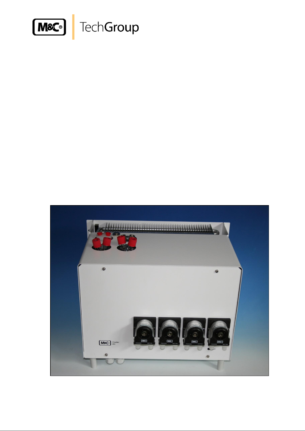
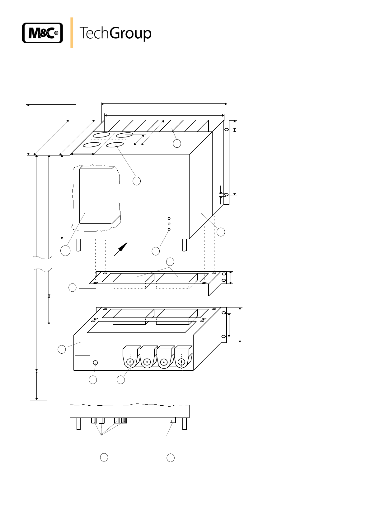
9 DESCRIPTION
Figure 2 shows the EC/ECS cooler unit with the optional universal units EC-F and EC-FD.
Figure 2 EC/ECS with options EC-F and EC-FD
Gas sampling and gas conditioning technology 3-4.1-ME
Page 11
11
The EC/ECS is equally suitable for wall installation or mounting in a 19“-rack.
The versions differ in the positioning of the LED function display . While for wall installation the LED
function display can be fitted into the corresponding cut-outs in the EC/ECS front panel, for 19”
rack mounting this is done using the cut-outs in the back panel of the casing. This positioning can be
done at the factory when stating the type of installation of the EC/ECS gas cooler. It is relatively
simple to subsequently reconfigure it on site at the user location. The location for installation of the
LED function display will be marked correspondingly.
The casing depth of the EC-.. cooler is 450mm. The ECS cooler unit differs in its less casing depth of
360mm and thereby is appropriate for mounting in a gas analysis cabinet with swing frame.
On the upper side of the cooler casing you will see the cut-outs for maximum 4 heat exchangers.
Sample gas enters and leaves the heat exchangers by the correspondingly connections on the upper
part of the heat exchangers.
At the rear part of the casing the condenser to remove heat given off in the compressor can be
seen.
The EC automatic control board is located in the plastic housing behind the removable front panel
of the EC/ECS casing.
On the underside of the casing the following connections are provided as standard:
Standard condensate outlets from the heat exchangers respectively,
Cable glands PG 13,5;
As standard, the condensate is removed externally with collecting vessels, peristaltic pumps SR25.1,
or by “over-pressure operation”, with automatic drawing-off of condensate, as e.g. type AD-... .
The heat energy from the cooling system is drawn off by a forced-ventilation . The required fans
and large air suction filter elements are provided as standard in This is arranged below the EC/ECS
casing and is absolutely essential for operation of the cooler unit.
Optionally, the automatic condensate removal unit EC-FD (10) with maximum 4 peristaltic pumps
SR25.1 (13) can by mounted by factory below the casing of the EC/ECS cooler. The fans and large
air suction filter elements guarantee the above-mentioned condenser forced ventilation and make
operation at higher ambient temperatures up to +50°C possible. The connection for the common
condensate outlet (12) is located in the front panel of the EC-FD unit.
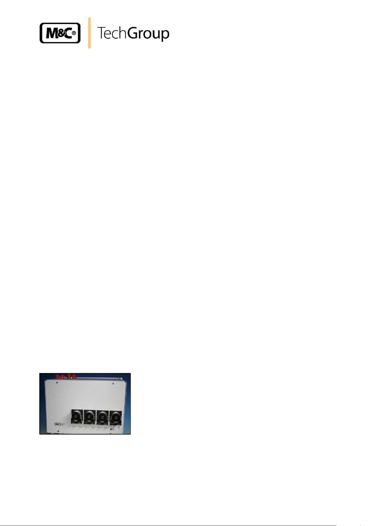
If no forced ventilation for the condenser is required, peristaltic pumps type SR25.2 can be build into
the front plate of the cooler (Part No. 01P9140).
Figure 3 Peristaltic pump SR25.2 mounted into the front panel
Instead of the unit EC-FD the universal unit EC-F optionally can be used for operation at higher
ambient temperatures up to +50°C without automatic condensate removal. The unit is mounted by
factory below the casing of the EC/ECS cooler and contains as well the above mentioned fans with
large air suction filter elements.
Gas sampling and gas conditioning technology 3-4.1-ME
Page 12
12
+5°C
Sample gas
out
Sample gas
in
Condensate out
Coolingblock
10 FUNCTION
The M&C EC/ECS gas cooler is a compressor cooler with status alarm capability. This ensures 100%
availability of the cooler.
Up to 4 Jet-stream heat exchangers made of Duran glass, PVDF or stainless steel are located in a
heat-insulated cooling block. All the heat exchangers are easily accessible and are arranged in such a
way that they can be removed very simply.
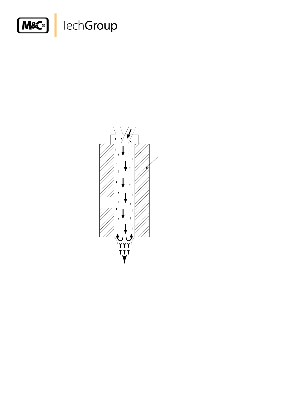
Figure 3 shows a schematic diagram of the functioning of the heat exchanger..
Figure 4 Schematic diagram of functioning of heat exchanger
The compressor cooler system has a heat-insulated cooling block at a constant temperature of +5°C.
Control of the compressor for models as from serial numbers 95... is done contactless by the EC
automatic control electronics and is therefore not subject to wear.
The novel construction of the heat exchanger guarantees a very good pre-separation of condensate
and for that reason an optimal drying of sample gas.
Alarm warnings for excess- and low-temperature are given as a collective status alarm via a relay
output with two potential-free changeover contacts. Alarm will be released if the current temperature
is out of a range of 3°C referring to the set-temperature (+5°C) .
Gas sampling and gas conditioning technology 3-4.1-ME
Page 13

13
NOTE!
The cooler must be stored in a weather-protected frost-free area!
NOTE!
During transport and when in storage, the cooler must always be stood up
with the transport feet positioned underneath so that the oil in the closed
compressor circuit cannot run out of this compressor case. If the cooler is
transported on its back by mistake, it must stood in the operating position
for approx. 24 hours before it is switched on!
NOTE!
Please state the desired type of mounting when ordering so that the LED
function display can be positioned to match at the factory!
NOTE!
The operating position for this cooler is exclusively vertical. This is the only
way to ensure proper separation and removal of condensate in the heat
exchangers. During transport and installation, the cooler must always be
stood up with the transport feet positioned underneath so that the oil in the
closed compressor circuit cannot run out of the compressor case.
The cooler should be kept away from sources of heat and well ventilated
when installed, so that condensation from warmth will not occur and
interfere with operation.
The minimum installation dimensions (fig. 2) must be followed without fail. If
the unit is installed in the open, the cooler must be installed in a housing
that is frost-free in winter and adequately ventilated in summer. Avoid
locating the unit in direct sunlight.
Unheated gas sample lines must be provided with slope up to the cooler. In
that case pre-separation of the condensate is not required.
Connect the heated sample line with sufficient thermal decoupling to the
cooler!
11 RECEPTION AND STORAGE
The EC/ECS gas cooler is a complete pre-installed unit.
Carefully inspect the EC/ECS and any special accessories included with it immediately on arrival
by removing them from the packing and checking for missing articles against the packing list!
Check the items for any damage in transit and, if required, inform the shipping insurance company
immediately of the damage found!
12 INSTALLATION INSTRUCTIONS
The EC/ECS cooler is equally suitable for wall mounting or for installation in a 19" rack.
Gas sampling and gas conditioning technology 3-4.1-ME
Page 14

14
NOTE!
Do not mix up the hose connections; the inlet and outlet connections of the
heat exchangers are marked with arrows;
Ensure that the connections are sealed adequately;
To ensure free removal of the condensate, ensure that the listed diameters
for the condensate removal lines are not reduced!
NOTE!
When fixing the connectors in the PVDF heat exchanger hold up with a
wrench at the pane of the bolt head!
13 SUPPLY CONNECTIONS
13.1 HOSE CONNECTIONS
The hoses for the heat exchangers are laid out as per Figure 3.
The connection for sample gas inlet and outlet happens on the upper part of the heat exchangers. For
possible connectors see technical data (3.).
Correspondingly tube or hose connectors are optional available by M&C.
Ensure that the connections are sealed adequately by noting the following:
Duran glass heat exchangers with connections GL 18-6 respectively GL 25-12
Before assembly, check the GL coupling rings to see if the PTFE/silicon locking rings have been
damaged.
To grant a functional and unproblematic mounting we recommend to use union pieces with taper
pipe thread type R according to DIN 2999/1 in connection with suitable sealing tape.
The sealing rings should be installed with the PTFE side facing the medium.
PVDF respectively stainless steel heat exchangers with G 1/4“i respectively G 3/8“i
The correspondingly dimensioned tube respectively hose couplings with threaded connections
have to be screwed in with PTFE thread sealing tape.
Option: stainless steel heat exchanger with NPT
The heat exchangers with NPT threaded connectors are marked with circulated notches.
The NPT thread must be screwed in with sealant or fixed with adhesive.
In the standard configuration, the tubes for removal of condensate are connected directly to the heat
exchangers. These protrude with the GL 25-12 tube connectors* (Duran glass heat exchanger)
respectively with G 3/8“* thread joint (PVDF or stainless steel heat exchanger) above the base plate
of the cooler casing (Fig.2).
Gas sampling and gas conditioning technology 3-4.1-ME
Page 15

15
NOTE!
Stainless steel heat exchangers with G 3/8“ thread joint can be directly fitted
up with the float-type condensate trap AD-SS by means of a thread adapter
part number FF 11000 (1/2“ NPT to G 3/8“i). By this wall mounting of the AD-
SS unit isn’t necessary!
WARNING!
When connecting the equipment, please ensure that the supply
voltage is identical with the information provided on the model
type plate.
NOTE!
Attention must be paid to the requirements of IEC 364 (DIN VDE
0100) when setting high-power electrical units with nominal
voltages of up to 1000 V, together with the associated standards
and stipulations.
Check the details on the type plate to ensure that the equipment is
connected up to the correct mains voltage.
The main circuit must be equipped with a fuse of 10AT (over
current protection); for electrical details see technical data.
Condensate removal is done by customer according to the type of operation with:
- Automatic float-type condensate traps AD-... only for over-pressure operation;
- Condensate collector container that is emptied manually;
- peristaltic pump.
Option: automatic condensate removal with peristaltic pump SR25.1 resp. SR25.2
In case of peristaltic pumps type SR25.2, build in the front plate, the condensate outlet 4/6 mm hose
is provided directly at the corresponding pump.
The Universal unit EC-FD with peristaltic pumps SR25.1 is equipped with a condensate outlet for
4/6mm hose connection on the front panel (see fig. 2).
13.2 ELECTRICAL CONNECTIONS
Gas sampling and gas conditioning technology 3-4.1-ME
Page 16

16
Power supply : 230V/50Hz or 115V/60Hz (see type plate)
Status alarm : two potential free changeover contacts
Contact rating : 250V AC, 2A, 500VA or
250V DC, 2A, 50W
Supply
main
18
19
20
L
N
PE
EC automatic
control electronics
27
28
303132
29
NC
MC
NO
NC
MC
NO
Status alarm
to PG 13,5
to PG 13,5
ECS
EC
Clamp connection X0 (from model nos. 96...)
123456789
10
NCMCNONCMCNOPENL
X0
Power connection to
EC electronics
Alarm connection to
EC electronics
Power In
by customer
Alarm connection by
customer
Figure 4 shows the electrical connections at the plastic housing behind the front panel of the EC/ECS
casing (Fig. 2).
Figure 5 Electrical sockets
For location of the clamp X0 see Fig.4 .
Figure 6 Pin configuration from model nos. 96...
Two PG 13.5 cable glands are provided for the cable bushings through the base plate of the cooler
casing. Further details are given in the pin configuration in Figure 5 below.
Gas sampling and gas conditioning technology 3-4.1-ME
Page 17

17
Netz ein
1 2 3
4
schwarz
schwarz
23
20
L
PE
M
51
50
49
N
48
27
29
28
30
31
32
15
13
14
16
17
19
22
44
45
46
EC-Sensor
Regelelektronik EC/ECS
Kompressor
Power in
Compressor
Universaleinheit EC-FD s. Anhang
Universal unit EC-FD see appendix
EC/ECS Automatic
NO
MC
NC
NO
NC
MC
18
21
24
40
41
42
43
47
1
2 3 1 3 2
230V
oder/or
115V
PT 100
~
M
~
M L N
PE
Universaleinheit
EC-F
Universal unit
<
<
Control electronics
black
black
s. Kapitel 13.1
see chapter 13.1
The 115V aggregate is forced
ventilated by connecting the
fan (90 K 0042a) to terminals
41, 45 respectively 49 or using
optional the universal units
EC-F/FD.
NOTE!
Before starting up the gas cooler, it must be placed i its operating
position for at least two hours. The liquid inside the system may have
been redistributed, and this could cause problems in operating!
Terminal
18
19
20
EC automatic control board
Connection
L N PE
Before model nos. 96... the pin configuration for power and alarm connection was as follows:
The power connector is on the front panel of the EC automatic control board. This is within the plastic
housing, behind the removable front panel of the cooler unit. The pin arrangement of the power
connector is as shown below (Fig. 4):
The potential-free contacts of the status collector alarm are located as well on the EC automatic
control board (Fig. 6), pins 27 to 32.
Figure 7 Pin configuration for EC/ECS up to model nos. 95...
14 START-UP
The automatic control electronics of the EC/ECS permit automatic start-up of the cooler. The error
diagnostics guarantee full monitoring and reporting of possible sources of error.
The following description is valid for start-up of the gas cooler for an ambient temperature > 8°C.
Gas sampling and gas conditioning technology 3-4.1-ME
Page 18

18
NOTE!
The status contacts must be connected to the external sample gas pump
or to a valve in the sample gas line to protect the entire analysis system
by immediately cutting off the gas supply in the event of error messages
from the cooler!
°C >
ON
°C <
red
pink
green
°C >
ON
°C <
pink
green
The following steps should be carried out before initial start-up:
Connect the cooler unit to the mains power supply;
Check that the equipment is connected to the correct mains voltage, 115V or 230V, as shown on
the type plate!
Lead the status contacts for reporting of under- and over-temperature to the measuring station;
14.1 FUNCTION SEQUENCE AND LED FUNCTION DISPLAY
Three function display LEDs are provided to give a visualization of the function sequence during startup of the cooler. According to the type of installation, they are located either on the front panel or the
back panel of the cooler (Fig. 2). The top LED (red) indicates that the temperature set by the EC
automatic control electronics has been exceeded or has not been reached. The two-colour
(pink/green) LED in the middle shows that the cooler compressor is operating. The bottom red
function display LED gives an alarm if the temperature falls too low.
Switching the cooler on
As soon as there is a mains voltage, the top red LED lights up. This indicates
that the temperature of the cooler is above +8°C. The two-coloured LED in
the middle lights up as pink once the cooler compressor is in operation.
Normal operation
After around 30 minutes the cooler has been cooled down to a temperature
below +8°C. The top red LED goes out.
The status collector alarm contacts are deactivated and control the automatic
external release for gas measurement.
The cooler compressor is switched of as soon as the cooler stage reaches
the controlled temperature of +5°C. The middle LED lights up as green.
The cooler compressor will be alternately switched on and off by the EC
automatic control electronics in a load-dependent cycle. The middle LED will
alternately light up as pink and green (normal operating functions).
Gas sampling and gas conditioning technology 3-4.1-ME
Page 19

19
NOTE!
The location for the cooler must remain frost-free, even when the
unit has been switched off!
WARNING!
Aggressive condensate is possible.
Wear protective glasses and proper protective clothing!
WARNING!
It is necessary to take the ECP electric gas cooler off the mains
before any assembly, maintenance or repair work is carried out !
15 CLOSING DOWN
If the cooler unit is putting out of action for a short time no particular measures need to be taken.
We recommended sweeping the cooler with inert gas or ambient air while the unit is putting out of
action for a longer time.
16 MAINTENANCE
The safety instructions specific to the plant and process are to be consulted prior to any maintenance
work!
The EC/ECS cooler unit does not require any special maintenance intervals.
16.1 CHANGE OF THE FILTER ELEMENT AT OPTION EC-F OR EC-FD
The air suction filter units in the EC- F / EC-FD universal unit are to be cleaned or replaced according
to the contamination level of the ambient air. They are located in a plug-in box underneath the cooler
unit. The filter elements are removed as follows:
Unclamp the plug-in box by turning the quick-lock screw plug 90° to the left;
Pull out the box;
Remove the crossbars holding the filter element by pulling with moderate force in the direction of
the filter element axis;
Remove and replace the filter elements.
Reassembly is done in the reverse order.
Gas sampling and gas conditioning technology 3-4.1-ME
Page 20

20
NOTE!
Do not mix up the hose connections; gas outlet and gas inlet are marked
with arrows!
When using automatic condensate removal by means of peristaltic pumps, the hoses of the peristaltic
pumps must be checked every three or six months, depending on the operating conditions, and
replaced if necessary. The procedure for changing the hoses is given in the corresponding operating
instruction SR25.
16.2 ADDING AND REPLACING THE HEAT EXCHANGERS
Removal of the heat exchangers may be necessary to carry out maintenance or repair work.
We recommend the following procedures and in this order for replacement of the heat exchangers:
Release the upper gas connections and lower condensate connections;
Pull the heat exchangers upwards with rotation out of the cooling block;
Replace the heat exchangers as follows:
Dry and clean the push-in opening in the aluminium cooling block with a cloth;
Smear the heat exchangers with a thin and equal layer over the whole surface with thermal
conductivity paste (part no. 90K0115) to ensure good conduction of heat. It is best to close off the
condensate removal of the heat exchangers tube with adhesive tape to prevent any of the thermal
conductivity paste from getting into the heat exchanger;
Lightly push the heat exchangers with rotation back into the push-in opening of the cooling block
and press to the upper block;
Remove the adhesive tape and any surplus thermal conductivity paste;
Reconnect the hoses.
Mounting the Duran glass heat exchangers please notice:
Check the PTFE/Silicon locking rings for damage. in assembly, the locking rings must have the
PTFE side facing the medium, otherwise the required degree of sealing cannot be guaranteed!
Do up the red GL coupling rings hand-tight by turning them to the right;
16.3 MAINTENANCE OF THE OPTIONAL MOUNTED PERISTALTIC PUMP(S), TYPE
SR25
Before the maintenance work is carried out, it is necessary hat the specific safety procedures
pertaining to the system and operational process are observed!
Gas sampling and gas conditioning technology 3-4.1-ME
Page 21

21
DANGER
Dangerous voltage!
It is necessary to take the pump off the mains before any assembly,
maintenance and repair work is carried out!
CARE!
Aggressive condensate is possible!
Wear protective glasses and proper protective clothing!
NOTE!
If you send back the peristaltic pump to the M&C service for repair,
please let us know what kind of condensate has been pumped.
Before sending the pump back clean all parts from dangerous or
highly aggressive contaminants.
1
2
3
4
Flexible tube, conveying belt, contact pulleys and contact springs are the only parts of the pump
subject to wear. They are simple to change.
16.3.1 CHANGE OF THE PUMP TUBE
Figure 8 Change of the pump tube
Take off the cooler of the mains;
Open hose connectors at the pump;
Press conveying belt at the recessed grips and turn S-bolt 2 clockwise up to limit stop;
Take away conveying belt and remove the old hose set from the guides by the hose
connectors;
Press the two contact pulleys and check whether the spring pressure is still sufficient, if not,
the contact springs have to be changed (s. 16.3.2);
Put the new hose set with the hose connectors into the guides of the conveying belt ;
Gas sampling and gas conditioning technology 3-4.1-ME
Page 22

22
NOTE!
Only the usage of the original hose set guarantees a perfect function.
Never lubricate the hose.
Before mounting the pump check all parts for impurity and clean if
necessary.
NOTE!
While mounting pay attention to the fit of ‘rotational axisdriver’.
Use genuine spare parts only!
CARE!
Aggressive sample is possible!
Wear protective glasses and proper protective clothing
during disassembly, repair or cleaning!
Put the conveying belt with the new hose into the dovetail guide of the pump body;
Press conveying belt at the recessed grips and simultaneously turn the S-bolt anticlockwise
until it snaps;
Switch on pump.
16.3.2 CHANGE OF CONTACT PULLEYS AND SPRINGS
Take off the cooler of the mains;
Unscrew the nut of the pump head (span of the jaw 5,5);
Draw the pump head out of the motor shaft;
Now the driver can picked out of the pump head and is ready for maintenance.
The removal of the springs (4 pcs.) away from the driver is possible without the aid of any
tools. Therefore press together the spring and take it out of the groove in the driver respectively
out of the boring in the axle. Now the roller bearing axle can be dismounted and the contact
pullets are ready for change.
Remounting happens in the opposite way.
16.3.3 CLEANING THE PUMP HEAD
When changing flexible tube or other parts, inspect all parts for dirt before assembling the
pump head and clean them if necessary.
As far as possible clean the parts with a dry cloth. Solvents should not be used as they can
attack the plastics and synthetic rubber parts. If a compressed air line is available, blow the
parts out with it.
Gas sampling and gas conditioning technology 3-4.1-ME
Page 23

23
LED display
Function error
and status
alarm
Probable cause
Checking / Correction
°C >
ON
°C <
Equipment
does not cool;
No mains power;
Check the mains voltage 230V (115V) at pins 18
and 19 of the EC automatic control electronics;
If mains voltage OK:
replace defective EC automatic control board.
°C >
ON
°C <
red
pink
Equipment does
not cool or the
cooling is
insufficient;
Cooling compressor is not running;
Check that the plugs are firmly seated in the sockets
for power connection to the compressor;
If OK:
Measure the voltage 230V/115V for the compressor
at the EC automatic control board at pins 21 and 22.
If not OK:
Replace the defective EC automatic control board;
If OK:
Does the red LED D3 on the EC automatic control
board lights up for more than one second?
(A blocked unit will be switched off by the motor
breaker switch);
If yes:
Replace the starting condenser;
If compressor does not run:
Send cooler in for repair.
°C >
ON
°C <
red
pink
See above
Cooling compressor runs; over-loading of the cooler
unit;
Check:
- Is the maximum of 250 l/h of gas flowing?
- Is the ambient temperature max. +45°C?
- Are the air suction filters dirty?
- Are the fans working?
- Are the condenser fins contaminated?
If OK:
Temperature at the EC automatic control board
(18.2);
If the temperature is < 8°C (< 0,8V) for a nominal
set temperature of 5°C:
Replace EC automatic control board;
If temperature > 8°C (>0,8V):
Check PT100 temperature sensor (19.);
If not OK:
Replace sensor;
If sensor and electronics OK:
Send cooler in for repair.
17 TROUBLE SHOOTING
Troubleshooting is made much easier by the LED function display.
The following table shows possible reasons for error and how to correct them (not applicable for the
running-up phase of the cooler).
Gas sampling and gas conditioning technology 3-4.1-ME
Page 24

24
LED display
Function error
and status
alarm
Probable cause
Checking / Correction
°C >
ON
°C <
green
red
Equipment does
not cool;
Cooler has been
over-cooled (temp.
< 2°C);
Ambient
temperature < 2°C
Cooling
compressor
stopped;
Cooling compressor runs continuously;
Ambient temperature must be ≥ 8°C!
Check temperature at EC automatic control board
(18.2);
If temperature < 2°C (< 0,2V):
Check PT100 temperature sensor (19);
If not OK:
Replace sensor.
Solid-state relay defective;
Replace EC automatic control board;
Gas sampling and gas conditioning technology 3-4.1-ME
Page 25

25
18 EC AUTOMATIC CONTROL BOARD
Figure 8 shows the arrangement of the EC automatic control board (wiring scheme in Appendix).
Figure 9 EC automatic control board
Gas sampling and gas conditioning technology 3-4.1-ME
Page 26

26
cable Nr.1
cable Nr.2
cable Nr.3
Condenser
230V 80uF
Art.Nr.:90K1055
115V 160uF
Art.Nr.:90K1060
from EC automatic control electronics
PE green/
yellow
cable Nr.1 from EC automatic control board pin 21
cable Nr.2 from EC automatic control board pin 24
cable Nr.3 from EC automatic control board pin 22
PE green/yellow from EC automatic control board
pin 23
Flat pin terminal Art.Nr KS5006
Klixon 230V Art.Nr.: 90K1046
Klixon 115V Art.Nr.: 90K1051
Control line Art.Nr.: KL0002
Connection cable
Art.Nr.: KL0001
Motor breaker switch:
Cable no. compressor
1 2 3
PE green/yellow
EC automatic control board
21
24
22
23
18.1 CONNECTING THE COOLING COMPRESSOR
The cooling compressor is connected to the EC automatic control board (Fig. 8). Figure 9 shows the
connection diagram for the compressor.
Figure 10 Connection diagram for compressor
Gas sampling and gas conditioning technology 3-4.1-ME
Page 27

27
NOTE!
Freezing-up in the cooling stage will endanger the operation of the cooler
unit. For this reason the cooler temperature must never fall below 2°C!
Current-Temp.
Ri > 100k
Setting-Temp.
P3
°C
+
-
Uref
Connect a d.c. voltmeter
to terminals 1, 2 and 3!
Uref
Utemp
R
C9
18.2 TEMPERATURE SETTING FOR THE EC/ECS COOLER
The EC/ECS gas cooler is set at the factory to a regulated temperature of +5°C.
Setting of the regulated temperature is
done by trimming potentiometer P3, on the
EC automatic control board of the cooler.
The setting range covers from 0°C to
20°C. Turning it to the right sets a lower
temperature, and turning it to the left sets
a higher temperature.
Connecting an external voltmeter to plugs
2 and 3 allows the nominal set
temperature to be read off and controlled.
A voltage value of 0.1V corresponds to a
temperature of 1°C.
It is possible to measure and control the
current temperature at measuring sockets
1 and 2.
18.3 CONNECTION OF AN EXTERNAL TEMPERATURE READING WITH OPTION
SECOND PT100 SENSOR (PART NO. 02K9500)
The second PT100 sensor is connected to the clamps 5 and 6 on the clamp block X2 (see fig. 8).
The external temperature reading is connected to the clamps 7 and 8. The connection cable is led
through one of the cable glands PG13,5 at the bottom plate of the cooler housing.
Gas sampling and gas conditioning technology 3-4.1-ME
Page 28

28
°C
Voltage
-3
-2
-1
0
1
2
3
4
-30 -20 -10 0 10 20 30 40
°C
Ohm
95
97
99
101
103
105
107
109
111
113
115
117
-10 0 10 20 30 40
19 CHECKING THE TEMPERATURE SENSOR
The EC/ECS cooler temperature sensor is a PT100 element as from serial numbers 95... . There are
two methods for checking the PT100 element, as follows:
1. Voltage method
In order to check the sensor for the cooler currently in operation, the actual voltage at the measuring
sockets 1 and 2 of the EC automatic control board must be measured as per section 18.2 above.
Figure 10 shows the voltage characteristics in relation to temperature. If the measured voltage is
inside the shaded area, the sensor is defective and must be replaced.
Figure 11 Voltage in relation to the temperature of the cooling stage
2. Resistance method
In this case the sensor must be disconnected from pins 1 and 2 at the EC automatic control board
(Fig. 8) and removed from the cooling block. When measuring the resistance of the PT100 element,
this must be proportional to the ambient temperature. The resistance-temperature characteristics are
shown in Figure 11 below.
Figure 12 Resistance-temperature characteristics of the PT100 temperature sensor
Gas sampling and gas conditioning technology 3-4.1-ME
Page 29

29
NOTE!
Before removing the cooler aggregate disconnect the cooler from all power
supplies;
Before mounting the new aggregate check, if voltage corresponds with the
specification on the type plate;
changing the cooler aggregate may only be carried out by qualified
personnel!
Front view
Top view
1 fastening screw cooler aggregate
2 fastening screw vaporizer
3 terminal for earth cable
4 vaporizer
5 compressor
6 valve for feeding with refrigerant
7 condenser
8 dryer
9 capillary tube
20 CHANGING THE COOLER AGGREGATE
According to the cooler version, forced ventilated or not, cooler aggregates with differing quantity of
refrigerant are available (spare parts list). As a spare part we deliver a complete replacement cooler
aggregate (230V- or 115V), including the compressor, vaporizer, condenser, dryer and the capillary
tube with the packaged refrigerant (230V R134A, 115V R404A). You send us your defective, non
damaged, complete cooler aggregate in a corresponding safe packing carton taking over the costs of
shipping.
Figure 12 shows the positioning of the cooler aggregate within the cooler casing.
Figure 13 EC cooler aggregate
Gas sampling and gas conditioning technology 3-4.1-ME
Page 30

30
NOTE!
If the LED function display is fitted in the front panel of the cooler casing
(wall mounting) pay attention that the display will not be damaged by
removing the front panel!
NOTE!
If replacing the LED function display please pay attention to the correct
position-ing (marked position respectively the connection cable points to
the base plate of the casing)!
For changing the cooler aggregate please carry out the following steps:
Remove the heat exchangers (16.2);
Loosen the fastening screws from the front panel of the cooler casing (Fig. 2);
Disconnect the earth wire of the front panel and remove the front panel;
If the LED function display is fitted in the back panel of the cooler casing (19“ version) it must be
pull out of the bracket before removing the cooler cover;
Loosen the fastening screws of the cooler cover;
Before removing the cooler cover disconnect the earth wire;
Disconnect the cooler compressor from the EC automatic control electronics (18.1). For this
remove the cap of the plastic housing (Fig. 2) and disconnect the cables from the corresponding
terminals (Fig. 5) (replacement cooler aggregate does not include connecting cables).
Disconnect the earth wire at terminal 3;
Loosen the fastening screws 1 of the cooler aggregate;
Loosen screw 2 in the aluminium cooling block (it is covered under the isolation and is not visible
from outside). For this push the isolation backwards;
Loosen the vaporizer 4 by vibrations in the middle of the cooling block. If the vaporizer is bind it is
possible to loosen it through a drilling in the base plate of the cooler by means of compressed air;
Lift the complete cooler aggregate (4, 5, 7) out of the cooler casing;
The mounting of the replacement cooler aggregate happens in opposite order. For this smear the
aluminium distributor block and the vaporizer sufficient with thermal conductivity paste (part number
90K0115).
After replacing the aggregate the cooler has to be start up according to the instructions given in
chapter 9. The cooler temperature can be controlled after approx. 30 minutes by means of a
thermometer in drilling 10.
Gas sampling and gas conditioning technology 3-4.1-ME
Page 31

31
Display
LCD 10mm, unit °C
Display range
-30°C to +30°C
Measuring period
2,5 per second
Ambient temperature range
0°C to +50°C
Main supply
4,5V to 15V, 2mA
Housing
ABS plastics black
Protection
IP50 for the front
IP00 for the back (DIN 40050)
Locating distance
30,5mm x 57mm (H x W)
Fitting length
73mm
NOTE!
The safety instructions specific to the plant and process are to be consulted
prior to installation, maintenance and inspection.
The cooler EC/ECS must be disconnected from all power supplies prior to
installation, maintenance and inspecttion!
°C>
ON
°C<
310
40
40
30,5
57
21 RETROFITTING A DIGITAL TEMPERATURE INDICATION
21.1 DATA FOR MOUNTING
Data according to the technical description DPM 528, Schwille Elektronik.
21.2 INSTALLATION INSTRUCTIONS
The digital temperature display is mounted in the front panel of the EC/ECS cooler. Figure 12 shows
the positioning and the necessary locating distance.
Figure 14 Locating distance of digital temperature indication
Gas sampling and gas conditioning technology 3-4.1-ME
Page 32

32
NOTE!
Attention must be paid to the requirements of VDE 0100 when setting UP
high-power electrical units with nominal voltages of up to 1000V together
with the associated standards and stipulations.
Check the details on the type plate to ensure that the cooler is connected up
to the correct mains voltage!
digital temperature display
cable [colour]
Meaning
8-channel connector
clamp point
yellow
+ 10V
11
brown
0V
12
green
1mV/°C
9
white
0V
12
For mounting the display and the temperature sensor please notice the following:
Loosen up the fixing screws of the front panel and remove it (see operating manual EC/ECS);
Remove the cooler cover (see operating manual EC/ECS);
Make the cut-out for the temperature display into the front panel according to the locating distance
shown in figure 13;
For cable bushings through the plastic housing of the EC/ECS control board please use the
available PG9 cable glands.
21.3 ELECTRICAL CONNECTIONS
The electrical connection of the digital temperature display happens on the EC/ECS control board (see
operation manual EC/ECS).
The temperature display is already equipped with all necessary cables.
The following steps must be done:
Loosen up the fixing screws of the cover of the plastic housing and remove the cover;
The cables of the digital temperature display have to be connected as follows:
Gas sampling and gas conditioning technology 3-4.1-ME
Page 33

33
Electric gas cooler EC/ECS
(C) consumable parts
(R) recommended spare parts
recommended quantity
EC/ECS being in operation
[years]
Part number
Description
C/R 1 2
3
02 K 9100
EC-G jet stream heat exchanger
material: Duran glass
R 1 1
1
02 K 9150
EC-G-90° jet stream heat exchanger
material: Duran glass
R 1 1
1
02 K 9200
EC-SS jet stream heat exchanger
material: stainless steel
R 1 1
1
02 K 9250
EC-SS/NPT jet stream heat exchanger
material: stainless steel
Connections: sample gas in and out 1/4“NPTi
condensate out 3/8“ NPTi
R 1 1
1
02 K 9300
EC-PV jet stream heat exchanger
material: PVDF
R 1 1
1
90 K 0115
EC thermal conductivity paste 50 g (-40°C to
140°C)
R 1 1
2
90 K 1002
Temperature sensor PT100 for EC automatic
control electronics from model nos.: 95.......
R
90 K 1007
EC automatic control board complete for PT100
and contactless compressor control
from model nos.: 95.......
R - 1
1
90 K 0035
Fan (M1/2 - 230V 50Hz)
with option EC-F/FD
C - 2
2
90 K 0040
Fan (M1/2 - 115V 60Hz)
with option EC-F/FD
C - 2
2
90 K 0042a
Fan 90mm X 90mm for EC 115V 60Hz
C - 2
2
90 K 1035
Solid-state-Relais "RE2" ASP-204
R - 1
1
90 K 1010
LED function display with connecting cable
R - -
1
90 K 1015
Cooler aggregate complete with compressor,
vaporizer and condenser for EC/ECS; refrigerant
R134A, power: 230 V, 50 Hz standard
R - -
-
90 K 1014a
Cooler aggregate complete with compressor,
vaporizer and condenser for EC/ECS; refrigerant
R404A, forced ventilated, power: 115 V, 60 Hz
R - -
-
90 K 1014
Cooler aggregate complete with compressor,
vaporizer and condenser for EC/ECS; special
quantity of refrigerant R134A for forced ventilation,
power: 230 V, 50 Hz with option EC-F/FD
R - -
-
90 K 0130
Filter cloth EC-F with option EC-F
C 2 4
6
or
90 K 0135
Filter cloth EC-FD with option EC-FD
C 2 4
6
90 K 1046
Bimetal switch Klixon 230V
R - 1
1
90 K 1051
Bimetal switch Klixon 115V
R - 1
1
90 K 1055
Capacitor for compressor 80µF-230V
R - 1
1
90 K 1060
Capacitor for compressor 160µF-115V
R - 1
1
22 SPARE PARTS LIST
Wear, tear and replacement part requirements depend on specific operating conditions.
The recommended quantities are based on experience and are not binding.
Gas sampling and gas conditioning technology 3-4.1-ME
Page 34

34
23 APPENDIX
Sample output dew point (ambient temperature 20°C) depending on gas flow rate
Circuit diagram EC automatic control board,
drawing number : 2300 - 5.04.2
Wiring plan automatic condensate removal unit EC-FD,
drawing number : 2300-5.05.0
More product documentation is available on our Internet catalogue:
www.mc-techgroup.com
Instruction manual peristaltic pump SR 25.1,
Document : 3-7.1-MD;
Condensate vessel TG, TK
Document : 3-6.3.1
GL-connectors
Document : 3-5.1.1
Universal unit EC-D and EC-FD
Document : 3-4.4
Automatic liquid drain AD-SS
Document : 3-6.2.3
Automatic liquid drain AD-P
Document : 3-6.2.1
Gas sampling and gas conditioning technology 3-4.1-ME
Page 35

35
Gasausgangs-Taupunkt
Sample outlet dewpoint
EC-G
10
5
187,5
125
250
°C
N l/h
Messgas-
Durchfluss
Gas flow rate
Gasausgangs-Taupunkt
Sample outlet dewpoint
EC-SS
10
5
°C
N l/h
Messgas-
Durchfluss
Gas flow rate
Gasausgangs-Taupunkt
Sample outlet dewpoint
EC-PV
10
5
°C
N l/h
Messgas-
Durchfluss
Gas flow rate
62,5
187,5
125
250
62,5
187,5
125
250
62,5
60°C
40°C
Sample output dew point (ambient temperature 20°C) depending on gas flow rate
sample inlet dew point
Figure 15 Sample outlet dew point
Gas sampling and gas conditioning technology 3-4.1-ME
Page 36

36
Figure 16 Circuit diagram EC automatic control board
Gas sampling and gas conditioning technology 3-4.1-ME
Page 37

37
Universaleinheit EC-FD
2300-5.05.0
Figure 17 Wiring plan automatic condensate removal unit EC-FD
Gas sampling and gas conditioning technology 3-4.1-ME
 Loading...