

Page 1
Instruction Manual
Electric Gas Cooler Series ECP
®
Versions ECP20-1 and ECP20-2 (from model nos.: 95...)
Gas sampling and gas conditioning technology 3-1.10-ME
Page 2

2
This Operating Manual does not claim completeness and may be
subject to technical modifications.
© 07/1995 M&C TechGroup Germany GmbH. Reproduction of this
document or its content is not allowed without permission from M&C.
ECP® is a registered trade mark.
3rd Edition: 12/2008
Dear customer,
we have made up this operating manual in such a way that all necessary information about the
product can be found and understood quickly and easily.
Should you still have any question, please do not hesitate to contact M&C directly or go through your
appointed dealer. Respective contact addresses are to be found in the annexe to this operating
manual.
Please also contact our homepage www.mc-techgroup.com for further information about our
products. There, you can read or download the data sheets and operating manuals of all M&C
products as well as further information in German, English and French.
Gas sampling and gas conditioning technology 3-1.10-ME
Page 3

3
List of Contents
1 General information ................................................................................................................ 4
2 Declaration of conformity ....................................................................................................... 4
3 Safety instructions .................................................................................................................. 5
4 Warranty .................................................................................................................................. 5
5 Used terms and signal indications ........................................................................................ 6
6 Application .............................................................................................................................. 7
7 Function of the M&C Jet-stream heat exchanger ................................................................ 8
8 Technical data ......................................................................................................................... 9
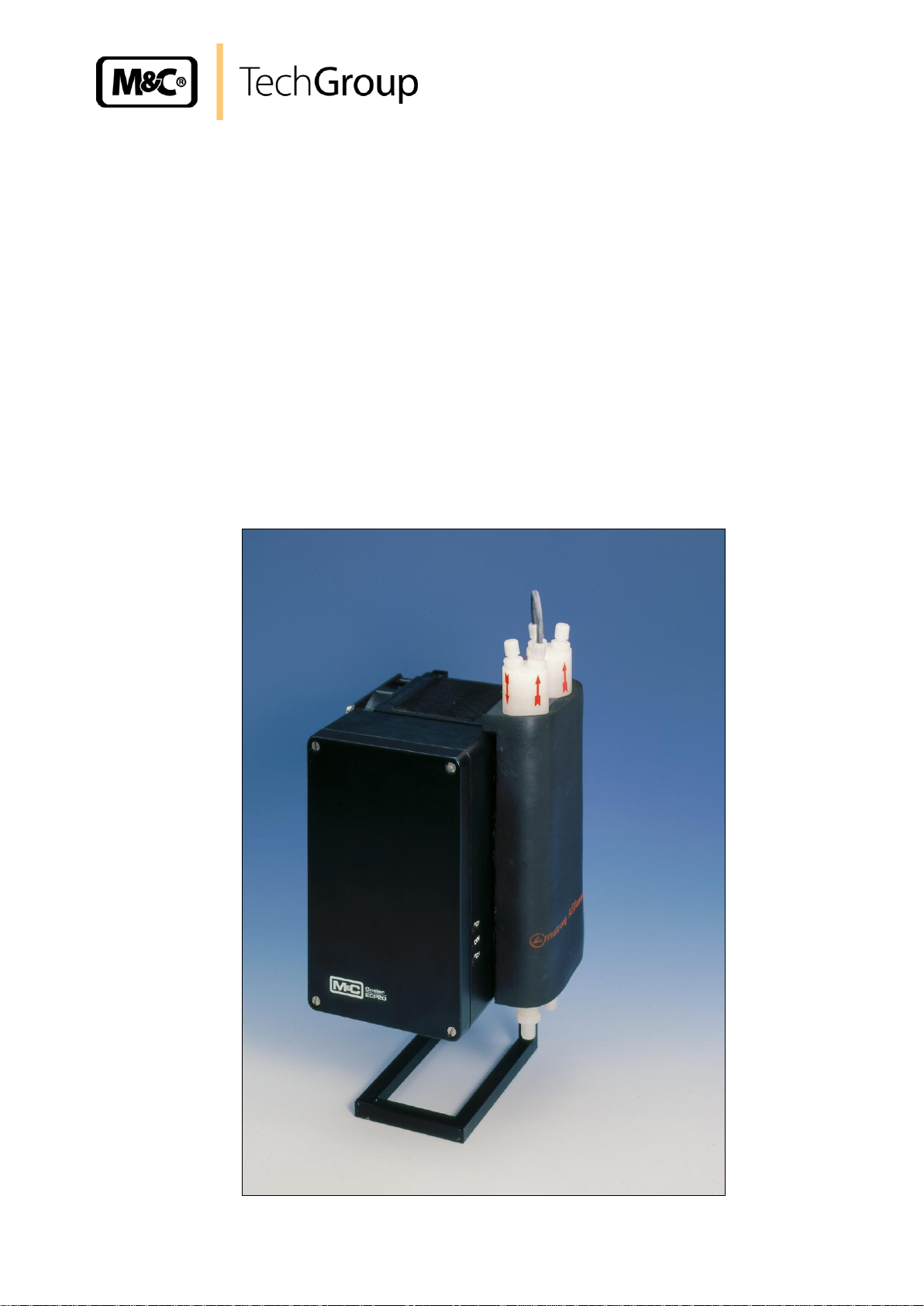
9 Description ............................................................................................................................ 10
10 Receipt of goods and storage ............................................................................................. 12
11 Installation instructions ....................................................................................................... 12
12 Supply connections .............................................................................................................. 13
12.1 Hose connections ............................................................................................................. 13
12.2 Electrical connections ...................................................................................................... 14
13 Starting .................................................................................................................................. 15
13.1 Function sequence and LED function display .................................................................. 15
14 Closing down ........................................................................................................................ 16
15 Maintenance .......................................................................................................................... 16
15.1 Adding and replacing the heat exchangers ...................................................................... 17
16 Trouble shooting ................................................................................................................... 18
17 Temperature setting and control the ECP cooler .............................................................. 19
18 Checking the temperature sensor ....................................................................................... 19
19 Spare parts list ...................................................................................................................... 21
20 Appendix ................................................................................................................................ 23
List of Figures
Figure 1 Application example of the ECP-20 .................................................................................. 7
Figure 3 Functioning diagram of the heat exchanger ...................................................................... 8
Figure 4 Electric gas cooler ECP20-1 and ECP20-2 ..................................................................... 10
Figure 5 Terminals for mains supply and temperature alarm ........................................................ 14
Figure 6 Temperature setting ........................................................................................................ 19
Figure 7 Voltage in relation to the temperature of the cooler ........................................................ 19
Figure 8 Resistance-temperature characteristics of the PT100 temperature sensor .................... 20
Gas sampling and gas conditioning technology 3-1.10-ME
Page 4

4
Head Office
M&C TechGroup Germany GmbH Rehhecke 79 40885 Ratingen Germany
Telephone: 02102 / 935 - 0
Fax: 02102 / 935 - 111
E - mail: info@mc-techgroup.com
www.mc-techgroup.com
1 GENERAL INFORMATION
The product described in this operating manual has been examined before delivery and left our works
in perfect condition related to safety regulations. In order to keep this condition and to guarantee a
safe operation, it is important to heed the notes and prescriptions made in this operating manual.
Furthermore, attention must be paid to appropriate transportation, correct storage, as well as
professional installation and maintenance work.
All necessary information a skilled staff will need for appropriate use of this product are given in this
operating manual.
2 DECLARATION OF CONFORMITY
CE - Certification
The product described in this operating manual complies with the following EC directives:
EMV-Instruction
The requirements of the EC directive 2004/108/EC “Electromagnetic compatibility“ are met.
Low Voltage Directive
The requirement of the EC directive 2006/95/EC “Low Voltage Directive“ are met.
The compliance with this EC directive has been examined according to DIN EN 61010.
Declaration of conformity
The EU Declaration of conformity can be downloaded from the M&C homepage or directly requested
from M&C.
Gas sampling and gas conditioning technology 3-1.10-ME
Page 5

5
3 SAFETY INSTRUCTIONS
Please take care of the following basic safety procedures when mounting, starting up or
operating this equipment:
Read this operating manual before starting up and use of the equipment. The information and
warnings given in this operating manual must be heeded.
Any work on electrical equipment is only to be carried out by trained specialists as per the regulations
currently in force.
Attention must be paid to the requirements of VDE 0100 (IEC 364) when setting high-power electrical
units with nominal voltages of up to 1000 V, together with the associated standards and stipulations.
Check the details on the type plate to ensure that the equipment is connected to the correct mains
voltage.
Protection against touching dangerously high electrical voltages:
Before opening the equipment, it must be switched off and hold no voltages. This also applies to any
external control circuits that are connected.
The device is only to be used within the permitted range of temperatures and pressures.
Check that the location is weather-protected. It should not be subject to either direct rain or moisture.
The equipment must not be used in hazardous areas.
Installation, maintenance, monitoring and any repairs may only be done by authorized personnel with
respect to the relevant stipulations.
4 WARRANTY
If the equipment fails, please contact M&C directly or else go through your M&C authorised dealer.
We offer a one year warranty as of the day of delivery as per our normal terms and conditions of sale,
and assuming technically correct operation of the unit. Consumables are hereby excluded. The terms
of the warranty cover repair at the factory at no cost or the replacement at no cost of the equipment
free ex user location. Reshipments must be send in a sufficient and proper protective packaging.
Gas sampling and gas conditioning technology 3-1.10-ME
Page 6
6
DANGER!
This means that death, severe physical injuries and/or important
material damages will occur in case the respective safety measures
are not fulfilled.
WA RN IN G!
This means that death, severe physical injuries and/or important
material damages may occur in case the respective safety
measures are not fulfilled.
CARE!
This means that minor physical injuries may occur in case the
respective safety measures are not fulfilled.
CARE!
Without the warning triangle means that a material damage may
occur in case the respective safety measures are not met.
AT TE NT ION!
This means that an unintentional situation or an unintentional status
may occur in case the respective note is not respected.
NOTE!
These are important information about the product or parts of the
operating manual which require user’s attention.
SKILLED STAFF
These are persons with necessary qualification who are familiar with
installation, use and maintenance of the product.
5 USED TERMS AND SIGNAL INDICATIONS
Gas sampling and gas conditioning technology 3-1.10-ME
Page 7
7
NOTE!
For protection against liquid breakthrough and to increase the dependability
of the complete system we recommend the use of a fluid alarm sensor.
Sample gas IN
+5°C
ECP-20
alternative :
condensate vessel
Test gas IN
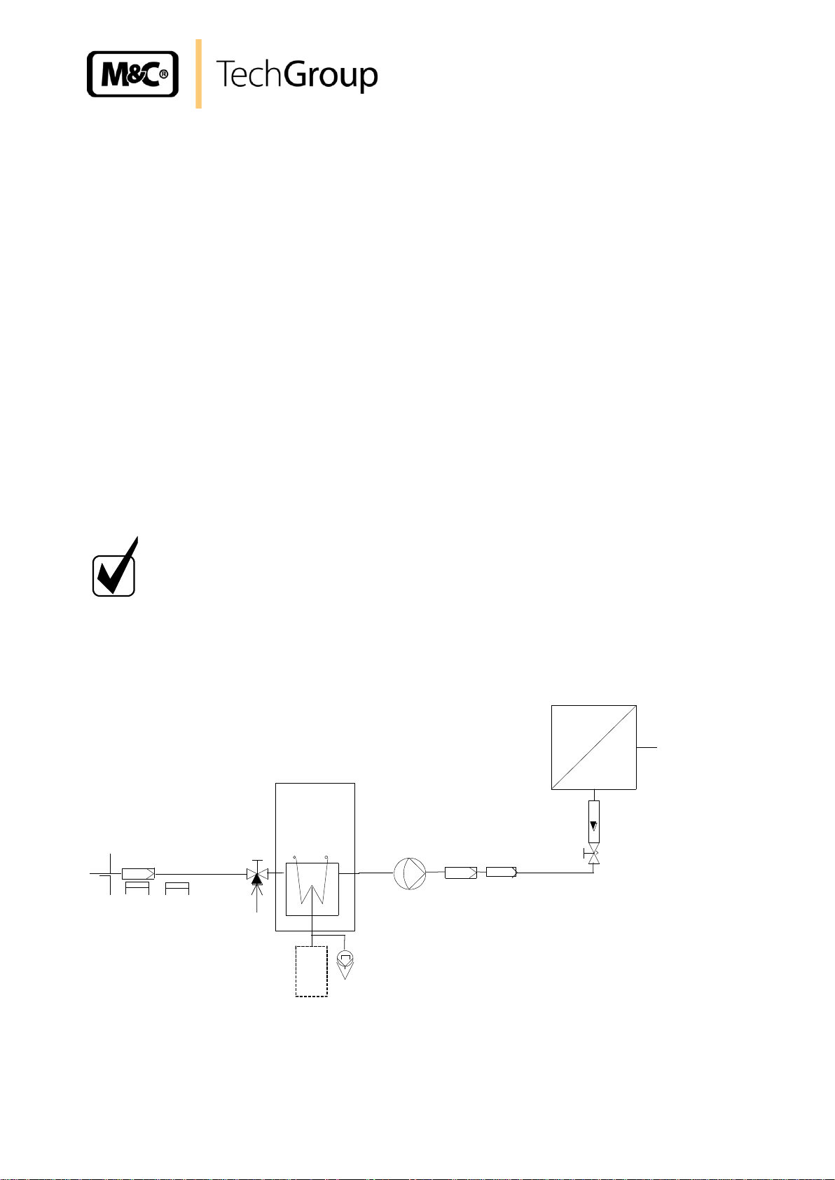
6 APPLICATION
The Peltier Gas Sample Cooler Type ECP20 is used in analyser sample system design to reduce the
dew point of wet gases to a level that is stable and low.
Sample gas cooling prevents subsequent condensation in the analyser. The stability of the dew point
is also extremely important at it helps to prevent water vapour cross sensitivity and volumetric error,
especially in infrared analysers.
The sample gas passes through a sampling probe to the Type ECP20 Cooler where it is lowered to a
dew point of +5°C. Solids will have been trapped in the filter of the sample probe, (If provided in the
type used) or are trapped in a downstream fine filter.
The conditioned gas can now be passed to the analyser.
If the analyser has no gas flow control or indicator functions, these should be provided externally, just
as with a gas delivery pump for unpressurized gases.
The condensate is discharged externally:
For operations under pressure, an automatic condensate drain or collection vessel is used.
For operations in partial vacuum (suction), a condensate vessel with a manual drain or a peristaltic
pump for automatic condensate removal is used.
For protection against liquid breakthrough and to increase the dependability of the complete system
we recommend the use of a fluid alarm sensor.
The Type ECP 20... Peltier Gas Coolers are designed for use in gas analysis whenever moisture is
likely to effect results.
The following figure shows the flow sheet of an typical application of the electric gas cooler
ECP 20....
1 : Filter sample probe SP ... 4 : 3-way ball valve 7 : Super fine filter FP ... 10 : Analyser
2 : Heating sample line 5 : Peristaltic pump (option) 8 : Aerosol filter CLF-5
3 : ECP-20 cooler 6 : Membrane pump 9 : Flow meter FM10
Figure 1 Application example of the ECP-20
Gas sampling and gas conditioning technology 3-1.10-ME
Page 8
8
+5°C
Sample gas
out
Sample gas
in
Condensate
out
Coolingblock
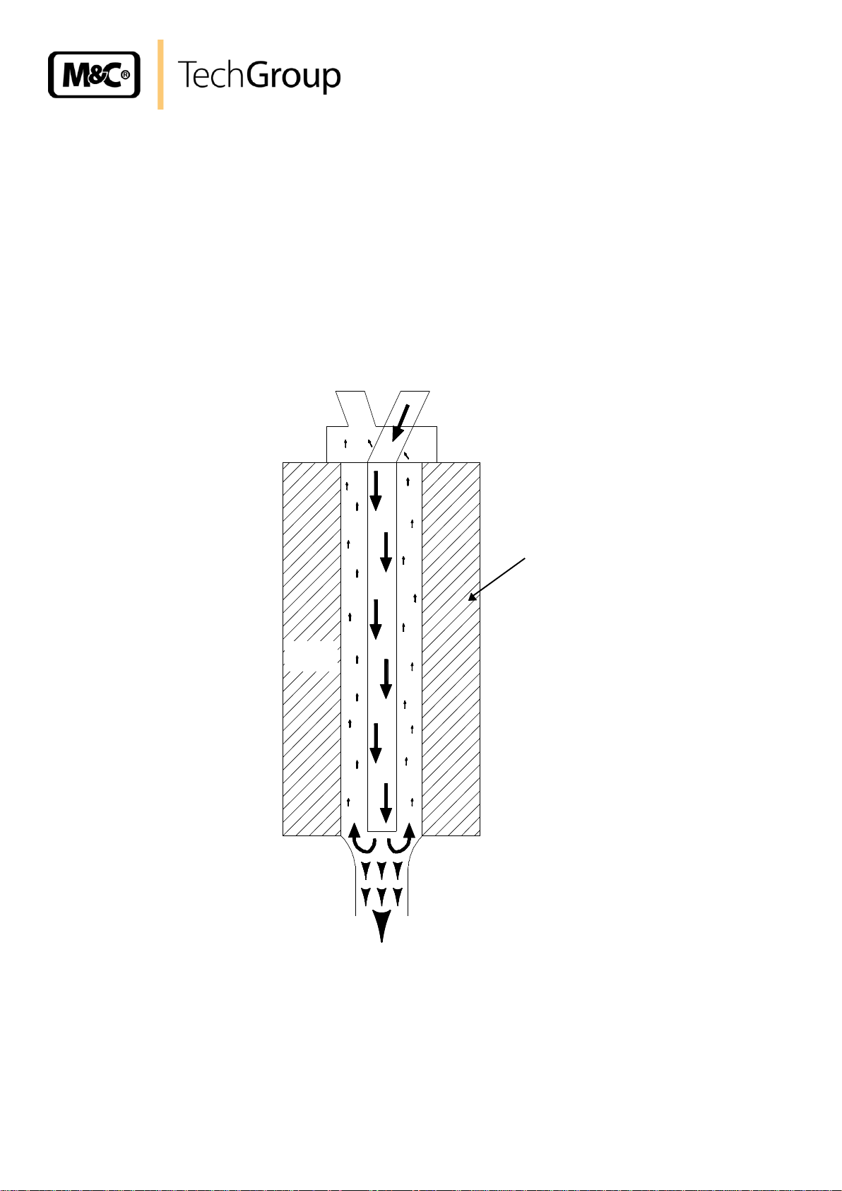
7 FUNCTION OF THE M&C JET-STREAM HEAT EXCHANGER
The ECP20-1 is equipped with one Jet-Stream heat exchanger for a flow rate of 250l/h while the
ECP20-2 has two heat exchangers in series for maximum flow of 500l/h.
The Jet-Stream heat exchangers made of Duran glass, optional PVDF or stainless steel are located in
a heat-insulated cooling block. All the heat exchangers are easily accessible and are arranged in such
a way that they can be removed very simply. Figure 2 shows a schematic diagram of the functioning of
the heat exchanger.
Figure 2 Functioning diagram of the heat exchanger
Gas sampling and gas conditioning technology 3-1.10-ME
Page 9

8 TECHNICAL DATA
Electric Gas Cooler ECP
Type ECP20-1
Type ECP20-2
Sample outlet dew point
range of adjustment: +2 °C ..... +15 °C, factory setting: +5 °C
Dew point stability
at const. conditions: < ±0,1°C
Sample inlet temperature
**max. 180°C
Sample inlet dew point
**max. 80°C
Gas flow rate
**max.250l/h
**max.500l/h
Number of heat exchangers
1
2
Material of heat exchangers
Duran glass or PVDF or stainless steel 316
Ambient temperature
**+5°C up to +40°C
Stockage temperature
-20 to +60°C
Admissible gas pressure
max. 3bar g. with glass and PVDF
max. 10bar with stainless steel
Total cooling capacity at 25°C a.t.
50KJ/h
80KJ/h
Dead volume/heat exchanger
approx. 80cm3
Sample gas connection
glass: for tube Ø6mm, PVDF/SS316: G1/4“i
Condensate connection
glass: for tube Ø12mm, PVDF/SS316: G3/8“i
Ready for operation
< 20 minutes
Mains power supply
switch 230V 50Hz or 115V 60Hz,(±10%)
Power consumption
150VA
250VA
Electrical connection
terminal 2,5mm2, cable glands 2 X PG11
Status alarm
contact rating 250V, 2A, 500VA, 50W alarm point 3°C to T
soll
Electrical protection
Fuse 2 x 4AT
Case protection
IP 54 (EN 60529)
Method of mounting
surface mounting
Casing dimensions (HxWxD)
210mm X 385mm X 226mm
Wight
10Kg
12,5Kg
Electrical equipment standard
EN 61010
9
* Standard,
** Maximum values in technical datas must be rated in consideration of total cooling capacity at 25 °C
ambient temperature and an outlet dew point of 5 °C.
Gas sampling and gas conditioning technology 3-1.10-ME
Page 10

9 DESCRIPTION
Netz/Power supply
PG11
Alarmkontakt PG11
Alarm Contact PG11
ECP20-1G
ECP20-2G
Figure 3 shows the ECP cooler unit.
10
Figure 3 Electric gas cooler ECP20-1 and ECP20-2
The type ECP20-1 Peltier Gas Sample Cooler is supplied completely with an EC Jet-Stream heat
exchanger made either of Duran glass, stainless steel or PVDF for a maximum flow of 250l/h.
The exchanger is housed for ease of replacement in a thermally insulated cooling block on the right
hand side of the cooler. From serial nos.: 95... the temperature is measured with a PT100 temperature
sensor and regulated electronically by Peltier Elements on a constant temperature of +5°C.
There are proof-plugs for checking the reference temperature and the current temperature, with an
output signal at 0,1 Volt/°C. (see Temperature Setting and Control).
The type ECP20-2 Peltier Gas Sample Cooler is supplied complete with two EC Jet-Stream heat
exchangers , one non regulated as a pre-cooler and the second regulated as a main cooler for a
maximum flow of 500l/h.
The system ensures optimum cooling of the sample gas and condensate separation.
The heat energy emitted by the cooling system is dissipated via a generously sized cooling fin block
with forced ventilation.
From serial no.: 9008023 the ECP20 coolers are equipped with a change-over switch on the control
board for operation at 230V 50Hz or 115V 60Hz. From serial nos.: 95... the switch is mounted on the
basic circuit board.
Gas sampling and gas conditioning technology 3-1.10-ME
Page 11

11
The electronic control system with status indication and the power supply unit are housed in a
protective aluminium enclosure on the front panel of the cooler.
There are three LED status indicators :
Upper red LED "°C >" = Temperature alarm > +8°C
Central green LED "On", lights or pulsates = Cooler on
Lower red LED "°C <" = Temperature alarm < +2°C
The green LED alone indicates that the specifications with regard to dew point temperature and dew
point stability are achieved. The red LED lights to indicates that the control system has deviated from
the setpoint by more than 3°C. The upper red LED "°C >" lights up to indicate an overload, i.e. more
cooling capacity is being called for than is available. The ECP20 Electric Gas Cooler is overloadprotected. In an overload condition the dew point temperature will rise proportional to the overload.
An over and under temperature alarm as a status group alarm is available for external indication, via a
relay output with a volt free relay changeover contact. The alarm thresholds are 3°C above and below
the control temperature.
The gas inlet and outlet is located on the top of the cooler and is indicated by arrows on the EC JetStream heat exchangers. On standard models with Duran glass heat exchangers the gas connections
are provided with GL18-6 mm PTFE sealing rings and on stainless steel or PVDF exchangers with
G1/4" female threads (or 1/4" NPT as optional).
The condensate drain of the EC Jet-Stream heat exchangers are located beneath the cooler and have
GL25-12 mm PTFE sealing rings as standard on the Duran glass heat exchangers. And on stainless
steel or PVDF exchangers with G3/8" female threads (or 3/8" NPT as optional).
The type of condensate discharge used will depend on the type of operation:
Peristaltic Pump Type SR25.1 for automatic condensate discharge in vacuum and pressurised
operations.
Automatic Float Condensate Discharge Type AD- .. for pressurised operation only.
Condensate Collection Vessel Type TG../TK.. with manual drain.
Option: Liquid alarm sensor LA..
For protection against liquid breakthrough and to increase the dependability of the complete system
we recommend the use of a liquid or condensate alarm sensor Type LA../KS.. with correspondingly
electronics mounted extern into the sample line between the cooler and the analyser.
Gas sampling and gas conditioning technology 3-1.10-ME
Page 12

12
NOTE!
The equipment should be stored in a protected, frost-free room!
NOTE!
The Cooler is to be used in a vertical position only! The perfect functioning
of the separation and drainage procedures will only be guaranteed if the
equipment is used in a vertical position!
When in use, the ECP cooler should be placed in an area well away from any
heat emitting sources in order to prevent damage caused by an
accumulation of heat the air vents must be free at all times!
When the equipment is being used outside, ample protection against the
effects of direct sunlight and dampness must be provided. In winter, the
equipment must only be used in frost-free areas!
Unheated gas sample lines must be provided with slope up to the cooler. In
that case pre-separation of the condensate is not required.
Connect the heated sample line with sufficient thermal decoupling to the
cooler!
10 RECEIPT OF GOODS AND STORAGE
The ECP gas cooler is a complete pre-installed unit.
Please take the ECP gas cooler and possible special accessories carefully out of the packaging
material immediately after arrival, and compare the goods with the items listed on the delivery note!
Check the goods for any damage caused during delivery and, if necessary, notify your transport
insurance company without delay of any damage discovered
11 INSTALLATION INSTRUCTIONS
The ECP 20.. Peltier Gas Cooler is designed for wall mounting and panel mounting as well.
Gas sampling and gas conditioning technology 3-1.10-ME
Page 13

13
NOTE!
Do not mix up the hose connections; the inlet and outlet connections of the
heat exchangers are marked with arrows;
Ensure that the connections are sealed adequately;
To ensure free removal of the condensate, ensure that the listed diameters
for the condensate removal lines are not reduced!
NOTE!
When fixing the connectors in the PVDF heat exchanger hold up with a
wrench at the pane of the bolt head!
NOTE!
Stainless steel heat exchangers with G 3/8“ thread joint can be directly fitted
up with the float-type condensate trap AD-SS by means of a thread adapter
part number FF 11000 (1/2“ NPT to G 3/8“i). By this wall mounting of the ADSS unit isn’t necessary!
12 SUPPLY CONNECTIONS
12.1 HOSE CONNECTIONS
The gas inlet and outlet is located on the top of the cooler and is indicated by arrows on the ECP JetStream heat exchangers. For possible connectors see technical data.
Correspondingly tube or hose connectors are optional available by M&C.
Ensure that the connections are sealed adequately by noting the following:
Duran glass heat exchangers with connections GL 18-6 respectively GL 25-12
Before assembly, check the GL coupling rings to see if the PTFE/silicon locking rings have been
damaged.
The sealing rings should be installed with the PTFE side facing the medium.
PVDF respectively stainless steel heat exchangers with G 1/4“i respectively G 3/8“i
The correspondingly dimensioned tube respectively hose couplings with threaded connections
have to be screwed in with PTFE thread sealing tape.
To grant a functional and unproblematic mounting we recommend to use union pieces with taper
pipe thread type R according to DIN 2999/1 in connection with suitable sealing tape.
Option: stainless steel heat exchanger with NPT
The heat exchangers with NPT threaded connectors are marked with circulated notches.
The NPT thread must be screwed in with sealant or fixed with adhesive.
In the standard configuration, the tubes for removal of condensate are connected directly to the heat
exchangers, with the standard GL 25-12 tube connectors (Duran glass heat exchanger) respectively
with the standard G 3/8“ thread joint (PVDF or stainless steel heat exchanger).
Condensate removal is done by customer according to the type of operation with:
- External peristaltic pump SR25.1;
- Automatic float type condensate traps AD-... only for over-pressure operation;
- Condensate collector container that is emptied manually;
Gas sampling and gas conditioning technology 3-1.10-ME
Page 14

14
WA RN IN G!
When connecting the equipment, please ensure that the supply
voltage is identical with the information provided on the model
type plate.
NOTE!
For the erection of power installations with rated voltages up to
1000V, the requirements of VDE 0100 and relevant standards and
specifications must be observed!
Set the voltage selector S1 to the correct mains voltage!
The main circuit is equipped with a fuse corresponding to the
nominal current (over current protection); for electrical details see
technical data.
1
L
2
N
4
PE
3PE5
L
6
N
123
4
X1
X2
Netz/Power
230V/115V
50Hz/60Hz
ECP20/1 150VA
ECP20/2 250VA
Alarm
250V AC
2A
500VA
ECP20/1, ECP20/2
Sicherung F1 4,0 AT
Fuse F2 4,0 AT
12.2 ELECTRICAL CONNECTIONS
The main power supply terminals are located in the aluminium enclosure on the ECP 20... electronic
board:
Power On, Terminal X1: 1, 2, 3 / L, N, PE
Coolers from serial nos.: 95.. also have a mains selector (S1) on the basic board for either 230V 50Hz
or 115V 60Hz operation on the basic circuit board (see circuit diagram in appendix).
Before commissioning, use a screwdriver to turn the selector to the correct position 230/115
depending on your main power input supply.
The status alarm contact for indicating and isolating the gas supply must be incorporated into the
equipment control system.
The volt free contact outputs of the status group alarm is located on the ECP 20.... control board:
Temp. Alarm Terminal X2: 1 and 3 normal opened, 2 and 4 normal closed.
The two PG11 cable glands are located on the underside of the cooler enclosure. For further details
refer to the electrical circuits and terminal drawing and cover plate.
Figure 4 Terminals for mains supply and temperature alarm
Gas sampling and gas conditioning technology 3-1.10-ME
Page 15

15
NOTE!
The status contacts must be connected to the external sample gas pump or
to a valve in the sample gas line to protect the entire analysis system by
immediately cutting off the gas supply in the event of error messages from
the cooler!
°C >
ON
°C <
red
°C >
ON
°C <
green
13 STARTING
Before using the equipment for the first time, check that the safety measures specific to the installation
and process are complied with!
The automatic control electronics of the ECP 20 permit automatic start-up of the cooler. The error
diagnostics guarantee full monitoring and reporting of possible sources of error.
The following description is valid for start-up of the gas cooler for an ambient temperature > 8°C.
The following steps should be carried out before initial start-up:
Connect the cooler unit to the mains power supply;
Lead the status contacts for reporting of under- and over-temperature to the measuring station;
13.1 FUNCTION SEQUENCE AND LED FUNCTION DISPLAY
Three function display LED’s are provided to give a visualisation of the function sequence during startup of the cooler. The top LED (red) indicates that the temperature set by the ECP automatic control
electronics has been exceeded or has not been reached. The central green LED shows that the cooler
is operating. The bottom red function display LED gives an alarm if the temperature falls too low.
Switching the cooler on
As soon as there is a mains voltage, the top red LED lights up. This
indicates that the temperature of the cooler is above +8°C.
Normal operation
After around 20 minutes the cooler has been cooled down to a
temperature below +8°C. The top red LED goes out.
The status collector alarm contacts are deactivated and control the
automatic external release for gas measurement.
The central green LED is alternately switched on and off by the ECP
automatic control electronics in a load-dependent cycle. The cooler is
ready to use.
Gas sampling and gas conditioning technology 3-1.10-ME
Page 16

16
NOTE!
The area in which the cooler is situated when not in use must be
kept free of frost at all times!
WA RN IN G!
Aggressive condensate possible.
Wear protective glasses and proper protective clothing!
WA RN IN G!
It is necessary to take the ECP electric gas cooler off the mains
before any assembly, maintenance or repair work is carried out!
14 CLOSING DOWN
If the cooler unit is putting out of action for a short time no particular measures need to be taken.
We recommended sweeping the cooler with inert gas or ambient air while the unit is putting out of
action for a longer time. Condensate has to be removed completely from the cooler.
15 MAINTENANCE
Before the maintenance work is carried out, it is necessary that the specific safety procedures
pertaining to the system and operational process be observed!
The ECP 20 Gas Cooler requires no particular routine maintenance. Depending on the quality of the
ambient air the cooling fin block should be blown out with compressed air from time to time.
Gas sampling and gas conditioning technology 3-1.10-ME
Page 17

17
WA RN IN G!
Aggressive condensate is possible.
Wear protective glasses and proper protective clothing!
15.1 ADDING AND REPLACING THE HEAT EXCHANGERS
Removal of the heat exchangers may be necessary to carry out maintenance or repair work.
We recommend the following procedures and in this order for replacement of the heat exchangers:
Release the upper gas connections and lower condensate connections;
Pull the heat exchangers upwards with rotation out of the cooling block;
Replace the heat exchangers as follows:
Dry and clean the push-in opening in the aluminium cooling block with a cloth;
Smear the heat exchangers with a thin and equal layer over the whole surface with thermal
conductivity paste (part no. 90K0115) to ensure good conduction of heat. It is best to close off the
condensate removal of the heat exchangers tube with adhesive tape to prevent any of the thermal
conductivity paste from getting into the heat exchanger;
Lightly push the heat exchangers with rotation back into the push-in opening of the cooling block
and press to the upper block;
Remove the adhesive tape and any surplus thermal conductivity paste;
Reconnect the hoses.
Do not mix up the hose connections; gas outlet and gas inlet are marked with arrows !
Mounting the Duran glass heat exchangers please notice:
Check the PTFE/Silicon locking Rings for damage. In assembly, the locking rings must have the
PTFE side facing the medium, Otherwise the required degree of sealing cannot be guaranteed;
Do up the red GL coupling rings hand-tight by turning them to the right;
Gas sampling and gas conditioning technology 3-1.10-ME
Page 18

18
Problem/Indication
Possible cause
Action/Check
ECP20 is not cooling
°C >
ON
°C <
°C >
ON
°C <
red
No mains supply
Ambient temperature
+2°C T +5°C
Temperature sensor faulty
Set point at Pot 3 out of
adjustment
Check for mains supply voltage at
terminals L&N, X1/1+2 against
nameplate. If OK, check fuses F1, F2.
Check ambient temperature.
Disconnect white wires from terminals
X5/5+6 and measure sensor resistance:
107,79 +0,4 Ohm at +20°C ambient; if
there is great deviation change the
sensor.
Adjust the desired temperature with the
trimmer Potentiometer P3 (0,1V/°C) and
control the current temperature at
terminals (X7/3) with an extern voltmeter
(see Temperature Setting and Control).
ECP20 cools
continuously
°C >
ON
°C <
red
Transistor BUZ11 faulty
Check voltage of the Peltier elements at
terminal X5, 1 and 3 respectively 2 and 4
(see circuit diagram):
> 12V DC = transistor faulty;
Fit the new transistor V1 on the basic
circuit board.
16 TROUBLE SHOOTING
The following table aims to point out possible operational problems and offer solutions to such
problems (not applicable during the starting procedure).
Gas sampling and gas conditioning technology 3-1.10-ME
Page 19

19
°C
Voltage
-3
-2
-1
0
1
2
3
4
-30 -20 -10 0 10 20 30 40
P3
+
-
Temperature
100mV/°C
Current
temperature
Ri>100K
Reference
temperature
17 TEMPERATURE SETTING AND CONTROL THE ECP COOLER
The gas cooler is set by manufacturer to a
control temperature of +5°C.
This temperature can be adjusted with a
trimmer Potentiometer P3 within a range
of 0°C to +20°C.
This Potentiometer is located on the
ECP20 control board.
Turning clockwise will increase the
temperature and turning counterclock will
decrease the temperature respectively.
To set the temperature it is measured at
the reference terminals (X7/1) using an
external DC-Voltmeter (0,1Volt/°C). The
current temperature can be measured at
terminals (X7/3).
Figure 5 Temperature setting
To prevent the heat exchangers freezing up, the temperature should never be set to below +2°C.
18 CHECKING THE TEMPERATURE SENSOR
The ECP20 cooler temperature sensor is a PT100 element as from serial numbers 95... . There are
two methods for checking the PT100 element, as follows:
1. Voltage method
In order to check the sensor for the cooler currently in operation, the actual voltage at the
corresponding measuring sockets must be measured (see ‘Temperature Setting and Control’). The
following figure shows the voltage characteristics in relation to temperature. If the measured voltage is
inside the shaded area, the sensor is defective and must be replaced.
Figure 6 Voltage in relation to the temperature of the cooler
Gas sampling and gas conditioning technology 3-1.10-ME
Page 20

20
°C
Ohm
95
97
99
101
103
105
107
109
111
113
115
117
-10 0 10 20 30 40
2. Resistance method
In this case the sensor must be disconnected from pins X5/5+6 at the ECP20 automatic control board
and removed from the cooling block. When measuring the resistance of the PT100 element, this must
be proportional to the ambient temperature. The resistance-temperature characteristics are shown in
the figure below.
Figure 7 Resistance-temperature characteristics of the PT100 temperature sensor
Gas sampling and gas conditioning technology 3-1.10-ME
Page 21

21
Electric Gas Cooler ECP20-1, ECP20-2
(C) consumable parts, (R) recommended spare parts, (S) spare parts
recommended quantity
ECP... being in operation
[years]
C/R/S
1 2 3
02 K 9100
EC-G Jet-Stream Heat Exchanger
Material: Duran Glass
Connections: Gas GL18-6/6mm
Condensate : GL25-12mm
R 1 1
1
02 K 9150
EC-G Jet-Stream Heat Exchanger with 90°
angled gas connections
Material: Duran Glass
Connections: Gas GL18-6/6mm
Condensate: GL25-12mm
R 1 1
1
02 K 9200
EC-SS Jet-Stream Heat Exchanger
Material: SS 316
Connections: Gas G 1/4" i
Condensate: G 3/8" i
R 1 1
1
02 K 9300
EC-PV Jet-Stream Heat Exchanger
Material: PVDF
Connections: Gas G 1/4" i
Condensate: G 3/8" i
R 1 1
1
90 K 0115
Heat sink compound 50g Type 80B522
R 1 1
2
93 K 0020
ECP20 Electronic Board complete
from serial nos.: 95...
R - 1
1
90 K 6030
4A fine-wire fuse 5mm x 20mm (F1/2)
R 2 4
4
90 K 0040
ECP Fan (M1/2 - 115V 60Hz)
C - 2
2
90 K 0045
Internal cable for connection of fan, incl. plug
R - -
1
90 K 2010
ECP20 Rectifier
R - 1
1
90 K 2020
ECP20 Power Transistor BUZ11
R - 1
1
90 K 2030
ECP20-1 Toroidal core transformer
115/230 V, 120VA
R - -
1
19 SPARE PARTS LIST
Wear, tear and replacement part requirements depend on specific operating conditions.
The recommended quantities are based on experience and are not binding.
Gas sampling and gas conditioning technology 3-1.10-ME
Page 22

22
Electric Gas Cooler ECP20-1, ECP20-2
(C) consumable parts, (R) recommended spare parts, (S) spare parts
recommended quantity
ECP... being in operation
[years]
C/R/S
1 2 3
90 K 2040
ECP20-2 Toroidal core transformer
115/230 V, 220VA
R - -
1
90 K 0075
ECP Peltier element
ECP20-1 = 2 off, ECP20-2 = 4 off
R - -
2/4
90 K 2090
PT100 temperature sensor for ECP
complete with screw and contact spring
R - -
1
90 K 2050
ECP20-1 Insulation
R - -
1
90 K 2060
ECP20-2 Insulation
R - -
1
90 K 0145
ECP Alarm Relay DSP1
R - -
1
Gas sampling and gas conditioning technology 3-1.10-ME
Page 23

23
20 APPENDIX
Sample output dew point (ambient temperature 20°C) depending on gas flow rate
Circuit diagram ECP20,
Drawing number : 2388-5.01.1
More product documentation is available on our Internet catalogue:
www.mc-techgroup.com.
Instruction manual peristaltic pump SR 25.1,
Document : 3-7.1-MD;
Condensate vessel TG, TK
Document : 3-6.3.1
GL-connectors
Document : 3-5.1.1
Automatic liquid drain AD-SS
Document : 3-6.2.3
Automatic liquid drain AD-P
Document : 3-6.2.1
Gas sampling and gas conditioning technology 3-1.10-ME
Page 24

24
4 5 6
7
8
9
10
Outlet dew
point [°C]
50
100
150
200
250
Sample gas flow [Nl/h]
Ambient temperature 20°C
Inlet
dew point:
60°C
40°C
Cooler EC-G / ECP-20 with Duran Glass Heat Exchanger
60°C
40°C
50
100
150
200
250
4
5
6
7
8 9 10
Cooler EC-G / ECP-20 with SS 316 Heat Exchanger
Outlet dew
point [°C]
Sample gas flow [Nl/h]
Inlet
dew point:
Cooler EC-PV / ECP-20 with PVDF Heat Exchanger
4 5 6
7
8
9
10
Outlet
dew point [°C]
50
100
150
200
250
Sample gas flow [Nl/h]
Inlet
dew point:
60°C
40°C
Ambient temperature 20°C
Gas sampling and gas conditioning technology 3-1.10-ME
Page 25

25
Figure 8 Circuit diagram ECP-20 from 07/97 on
Gas sampling and gas conditioning technology 3-1.10-ME
 Loading...