

Page 1

Operating Manual
Electric gas cooler series EC
®
Version EC-EX (from model nos. 9904417)
Gas sampling and gas conditioning technology 3-4.1ME EC-EX 9904
Page 2

2
This Operating Manual does not claim completeness and may be
subject to technical modifications.
© 09/1999 M&C TechGroup Germany GmbH. Reproduction of this
document or its content is not allowed without permission from M&C.
EC® is a registered trade mark.
4th Edition: 09/2004
Dear customer,
we have made up this operating manual in such a way that all necessary information about the
product can be found and understood quickly and easily.
Should you still have any question, please do not hesitate to contact M&C directly or go through your
appointed dealer. Respective contact addresses are to be found in the annexe to this operating
manual.
Please also contact our homepage www.mc-techgroup.com for further information about our
products. There, you can read or download the data sheets and operating manuals of all M&C
products as well as further information in German, English and French.
Gas sampling and gas conditioning technology 3-4.1ME EC-EX 9904
Page 3

3
List of Contents
1 General information ...................................................................................................................... 4
2 Declaration of conformity ............................................................................................................ 4
3 Electrical standards ...................................................................................................................... 5
4 Safety instructions ....................................................................................................................... 5
5 Information and safety instructions for using the cooler in hazardous areas ........................ 6
6 Warranty ........................................................................................................................................ 6
7 Used terms and signal indications ............................................................................................. 7
8 Introduction ................................................................................................................................... 8
9 Application .................................................................................................................................... 8
10 Technical data ............................................................................................................................... 9
11 Description .................................................................................................................................. 10
12 Function ....................................................................................................................................... 12
13 Reception and storage ............................................................................................................... 13
14 Installation instructions ............................................................................................................. 13
15 Supply connections .................................................................................................................... 14
15.1 Hose connections ............................................................................................................... 14
15.2 Electrical connections ........................................................................................................ 15
16 Start-up ........................................................................................................................................ 16
16.1 Function sequence and LED function display .................................................................... 17
17 Closing down .............................................................................................................................. 18
18 Maintenance ................................................................................................................................ 18
18.1 Adding and replacing the heat exchangers ........................................................................ 19
19 Trouble shooting ........................................................................................................................ 20
20 EC automatic control board ....................................................................................................... 22
20.1 Temperature setting for the EC/ECS cooler ....................................................................... 23
21 Checking the temperature sensor ............................................................................................. 24
22 Spare parts list ............................................................................................................................ 25
23 Appendix ..................................................................................................................................... 26
List of Illustrations
Figure 1 Example of application of EC-EX ........................................................................................ 8
Figure 2 EC-EX cooler .................................................................................................................... 10
Figure 3 Functioning of heat exchanger .......................................................................................... 12
Figure 4 Electrical sockets .............................................................................................................. 15
Figure 5 EC-EX automatic control board ......................................................................................... 22
Figure 6 Temperature setting .......................................................................................................... 23
Figure 7 Temperature sensor resistance ........................................................................................ 24
Figure 8 Sample outlet dew point .................................................................................................... 27
Figure 9 Schematic drawing ............................................................................................................ 28
Figure 11 Circuit diagram EC-EX 230V/50Hz ................................................................................... 29
Figure 12 Circuit diagram EC-EX 115V/50-60Hz .............................................................................. 30
Gas sampling and gas conditioning technology 3-4.1ME EC-EX 9904
Page 4
4
Head Office
M&C TechGroup Germany GmbH Rehhecke 79 40885 Ratingen Germany
Telephone: 02102 / 935 - 0
Fax: 02102 / 935 - 111
E - mail: info@mc-techgroup.com
www.mc-techgroup.com
1 GENERAL INFORMATION
The product described in this operating manual has been examined before delivery and left our works
in perfect condition related to safety regulations. In order to keep this condition and to guarantee a
safe operation, it is important to heed the notes and prescriptions made in this operating manual.
Furthermore, attention must be paid to appropriate transportation, correct storage, as well as
professional installation and maintenance work.
All necessary information a skilled staff will need for appropriate use of this product are given in this
operating manual.
2 DECLARATION OF CONFORMITY
CE - Certification
The product described in this operating manual complies with the following EC directives:
ATEX-Directive
The product described in this manual is produced in accordance with the EC directive for devices and
protection systems for appropriate use in hazardous areas 94/9/EG appendix II.
EMV-Instruction
The requirements of the EC directive 2004/108/EC “Electromagnetic compatibility“ are met.
Low Voltage Directive
The requirement of the EC directive 2006/95/EC “Low Voltage Directive“ are met.
The compliance with this EC directive has been examined according to DIN EN 61010.
Declaration of conformity
The EU Declaration of conformity can be downloaded from the M&C homepage or directly requested
from M&C.
Gas sampling and gas conditioning technology 3-4.1ME EC-EX 9904
Page 5

5
3 ELECTRICAL STANDARDS
The electrical standard of electrical equipment corresponds to the safety regulations concerning the
EN61010, EN 50014 A1 to A5, EN 50016 A1, EN 50017 A1, EN 50018 A1 to A3, EN 50019 A1 to A3
and EN 50020 A1 to A2, for operating in hazardous areas Group II Category 2G. Attention must be
paid to the certificate of conformity KEMA 03ATEX2113 (see appendix).
4 SAFETY INSTRUCTIONS
Please note the following basic safety procedures when using this equipment:
Read these operating instructions carefully before start-up and use of the equipment! The
information and warnings given in these operating instructions must be heeded.
Attention must be paid to the requirements of the certificate of conformity (see appendix): 03
ATEX 2113.
Work on electrical equipment is only to be carried out by trained specialists as per the
regulations currently in force.
Attention must be paid to the requirements of VDE 0100 when setting high-power electrical
units with nominal voltages of up to 1000V, together with the associated standards and
stipulations.
For use in hazardous area observe the relevant national and international instructions and
regulations.
Check the details on the type plate to ensure that the equipment is connected up to the correct
mains voltage.
Protection against touching dangerously high electrical voltages. Before opening the
equipment, it must be switched and hold no voltages. This also applies to any external control
circuits that are connected.
The equipment is only to be set within the permitted range of temperatures and pressures.
Check that the location is weather-protected. It should not be subjected to either direct rain or
moisture.
Installation, maintenance, monitoring and any repairs may only be done by authorised
personnel with respect to the relevant stipulations.
Gas sampling and gas conditioning technology 3-4.1ME EC-EX 9904
Page 6

6
5 INFORMATION AND SAFETY INSTRUCTIONS FOR USING THE COOLER IN
HAZARDOUS AREAS
The compressor cooler EC-Ex is suitable for using in hazardous area category 2G.
The explosion proof protection is:
230V / 115 : II 2 G EEx pedq [ib] IIC T4 (appr.-no.: 03 ATEX 2113)
The certification of the cooler was done by the Kema the authorized institute of electrical equipment in
the Netherlands. For detailed information and a copy of the certificate see appendix.
Installation and operating of the cooler has to be done corresponding to the conditions fixed in the Excertificate (see appendix). Only in this case the reliability of the operation in the hazardous area can
be guaranteed.
All changes of the standard configuration with parts which are not specified or approved by M&C as
well as repair and service with not specified parts means a loss of the Excertificate.
In case of doubt please turn directly to M&C respectively to your M&C franchised dealer.
6 WARRANTY
If the equipment fails, please contact M&C directly or else go through your M&C authorised dealer.
We offer a one year warranty as of the day of delivery as per our normal terms and conditions of sale,
and assuming technically correct operation of the unit. Consumables are hereby excluded. The terms
of the warranty cover repair at the factory at no cost or the replacement at no cost of the equipment
free ex user location. Reshipments must be send in a sufficient and proper protective packaging.
Gas sampling and gas conditioning technology 3-4.1ME EC-EX 9904
Page 7
7
DANGER!
This means that death, severe physical injuries and/or important
material damages will occur in case the respective safety measures
are not fulfilled.
WARN I N G!
This means that death, severe physical injuries and/or important
material damages may occur in case the respective safety
measures are not fulfilled.
CARE!
This means that minor physical injuries may occur in case the
respective safety measures are not fulfilled.
CARE!
Without the warning triangle means that a material damage may
occur in case the respective safety measures are not met.
ATT E NT I ON!
This means that an unintentional situation or an unintentional status
may occur in case the respective note is not respected.
NOTE!
These are important information about the product or parts of the
operating manual which require user’s attention.
SKILLED STAFF
These are persons with necessary qualification who are familiar with
installation, use and maintenance of the product.
NOTE!
These are important information about the product or parts of the
instruction manual referring to operating in hazardous areas.
7 USED TERMS AND SIGNAL INDICATIONS
Gas sampling and gas conditioning technology 3-4.1ME EC-EX 9904
Page 8
8
Sample gas
in
+5°C
EC-EX
Collecting vessel
Checkgas in
8 INTRODUCTION
The M&C EC-EX gas cooler unit is always to be installed in situations where there is interference from
moisture in the gas to be measured and if the point of installation is declared as hazardous area (see
appendix).
Reduction of the gas temperature inside the cooler to a stable and very low dew point effects a
condensing-out of the sample gas.
9 APPLICATION
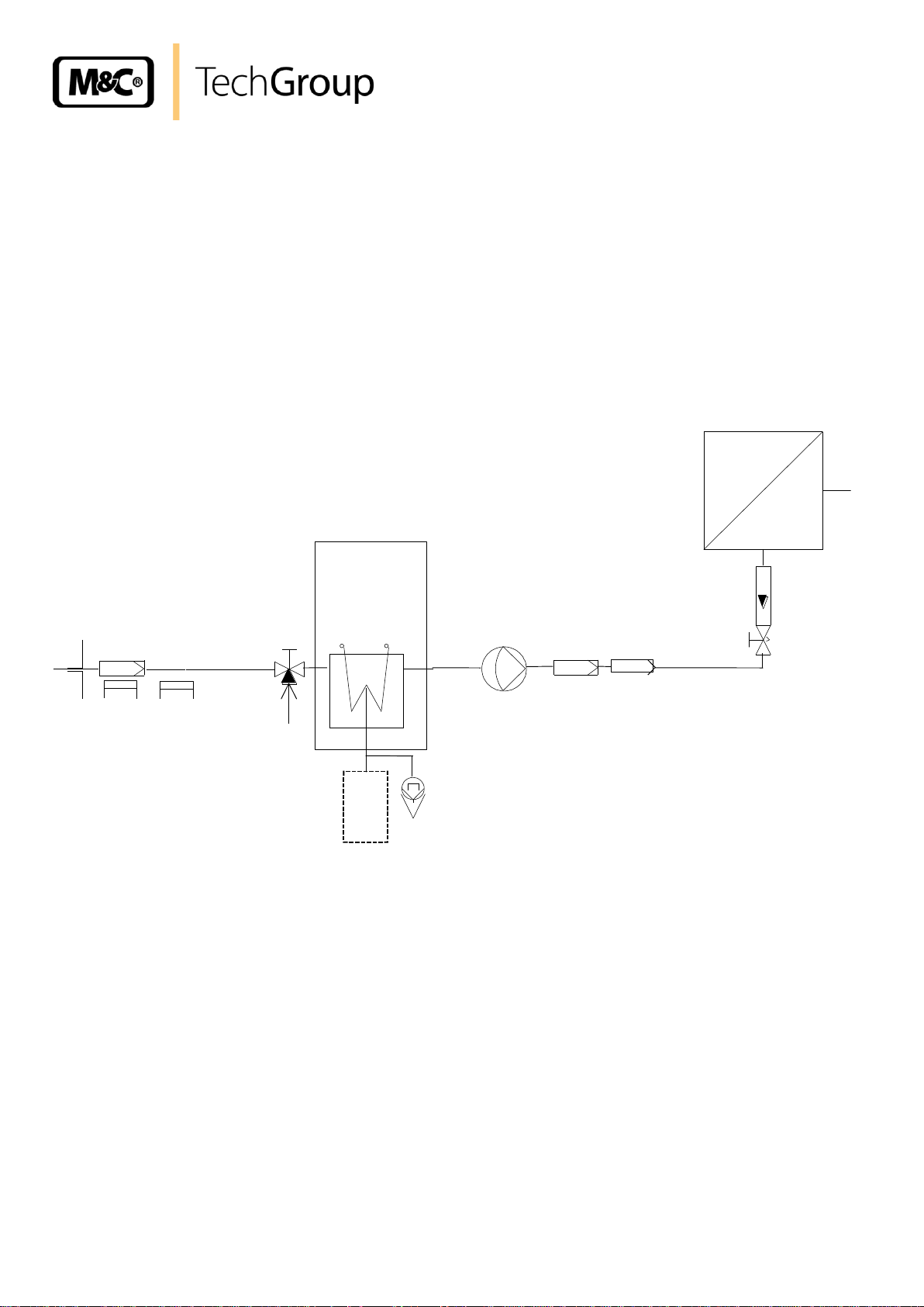
Figure 1 shows a typical example of an application for installation of an EC-EX gas cooler unit.
Filter sample probe SP2000-H/Ex 3-way ball valve Super-fine filter FP...
Heated sample line Ex-version Peristaltic pump SR25.1/Ex Aerosol filter CLF
EC-EX cooler Membrane pump MP47/Ex Flow meter FM 10
Figure 1 Example of application of EC-EX
The gas to be measured is taken from the EC-EX gas cooler by a gas sample probe and cooled
down to a dew point of +5°C. The super-fine filter located afterwards removes solid particles. For
increased operating safety of the entire system we recommend installing a super-fine filter with a
liquid alarm sensor (for example LA1 with electronic controller type ER 142 Exi). If required an aerosol
filter can be installed in front of the flow meter . The gas thus treated can now be passed into the
analyser .
Gas sampling and gas conditioning technology 3-4.1ME EC-EX 9904
Analyser PMA50 Ex
Page 9
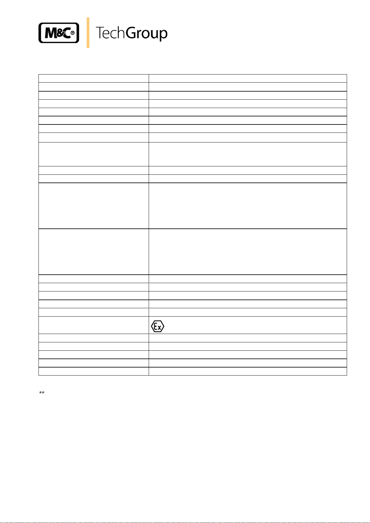
10 TECHNICAL DATA
Sample outlet dew point
range of adjustment: +2 °C ..... +7 °C, factory setting: +5 °C
Dew point stability
at constant conditions 0,25°C
Sample inlet temperature
**Max. + 180°C
Sample inlet dew point
**Max. +80°C
Gas flow rate per heat exchanger
**Max. 250l/h
Number of heat exchangers
1*, installation of max. 4 heat exchangers possible
Material of heat exchangers
Borosilicate glass or PVDF or stainless steel 316
Ambient temperature
**+0 to +45°C
Admissible gas pressure
with glass and PVDF: max. 3 bar
with stainless steel : 10 bar*
with option EC-FD : 1,2 bar
Total cooling power
Max. 520 KJ/h at +25°C
Dead volume per heat exchanger
70 ml
Sample gas connection glass:
PVDF:
stainless steel:
For tube 6mm*,
option: 8mm, 10mm or hose connector
G 1/4“i,
option: hose connector
G 1/4“i*,
option: NPT or hose connector
Condensate connection glass:
PVDF:
stainless steel:
For tube 12mm*,
option: 8mm, 10mm or hose connector
G 3/8“i,
option: hose connector
G 3/8“i*,
option: NPT or hose connector
Ready for operation
< 30 minutes
Power consumption
280VA, start up current at 230V = 8,1A at 115V= 17A
Mains power supply
230V 50Hz +/- 10% *, or 115V 50-60Hz +/- 10%
Electrical connections
Terminal 2,5 mm²
Status alarm
1 changeover contact, max. 230V 2A AC/DC 100VA, 50W
Ex-Protection
II 2G EEx p e d q [ib] IIC T4
Casing colour
RAL 9003
Method of mounting
19“ rack or wall mounting
Casing dimensions
84 TE x 7 HE x 450mm, 40 kg
Refrigerant
R134A 100% CFC free
Electrical equipment standard
EN 61010
9
* standard
Maximum values in technical datas must be rated in consideration of total cooling capacity at 25 °C
ambient temperature and an outlet dew point of 5 °C.
Gas sampling and gas conditioning technology 3-4.1ME EC-EX 9904
Page 10
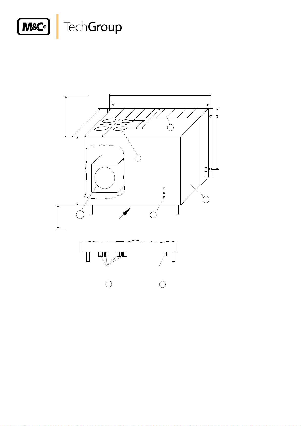
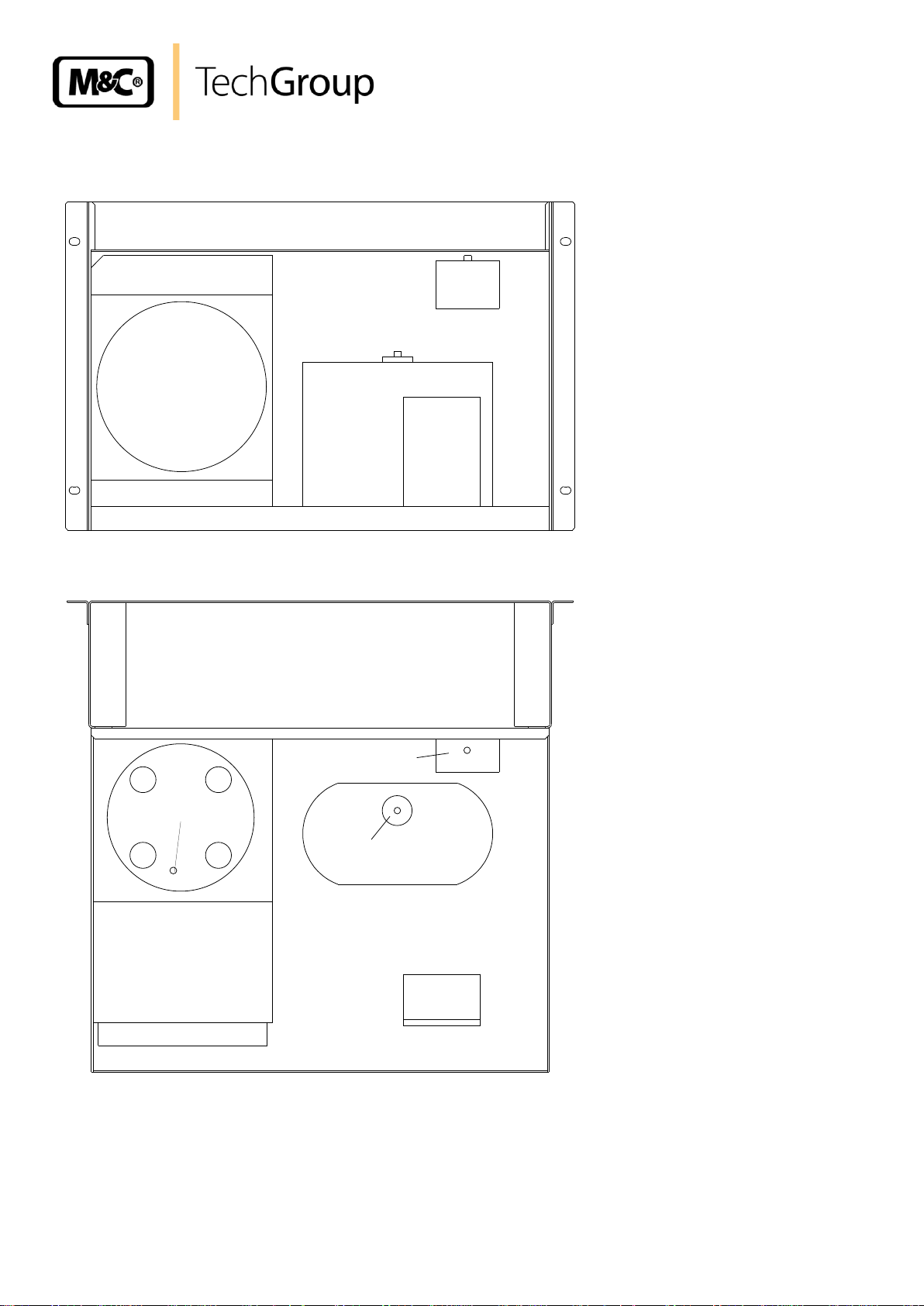
11 DESCRIPTION
°C>
ON
°C<
A
235
310
435
1
2
4
3
37,5
6,2
* necessary locating distance
240
70
85
88 * 2HE
100 *
7 HE
465
84 TE
View A
2 X cable glands
PG 13,5
max. 4 X condensate out
6
7
450
5
Figure 2 shows the EC-EX cooler unit .
10
Figure 2 EC-EX cooler
The EC-EX is equally suitable for wall installation or mounting in a 19“ rack.
The versions differ in the positioning of the LED function display . While for wall installation the LED
function display can be fitted into the corresponding cut-outs in the EC-EX front panel, for 19” rack
mounting this is done using the cut-outs in the back panel of the casing. This positioning can be done
at the factory by when stating the type of installation of the EC-EX gas cooler. It is relatively simple to
subsequently reconfigure it on site at the user location. The location for installation of the LED function
display will be marked correspondingly.
The casing depth of the EC-EX cooler is 450mm. Additional installations within the casing aren’t
possible.
The electrical parts of the cooler EC-EX are explosion protected. The EC-EX control board and the
protective motor switch are mounted in a flameproof enclosure EEx-d .
Gas sampling and gas conditioning technology 3-4.1ME EC-EX 9904
Page 11

11
NOTE!
The manual Reset for the pressure alarm is cancelled since September 2004.
The cooler is switched off continuously in case of a leaking cooling system!
The EC-EX cooling compressor has a special junction box and one surface area temperature alarm
contact with manual reset button. The refrigeration circulation suction side of the EC-EX compressor
has a pressure alarm unit with manual reset button.
This alarms are connected into the Ex-i-circuit and to switch off the voltage of the compressor during
compressor temperature alarm or pressure alarm.
The EC-EX cooler in 230V-version has two EEx-q compressor start capacitors, the EC-EX cooler in
115V-version three.
The electrical connectors for mains power supply and the alarm contact output are located in the
EEx-e terminal box.
On the upper side of the cooler casing you will see the cut-outs for maximum 4 heat exchangers.
Sample gas enters and leaves the heat exchangers by the correspondingly connections on the upper
part of the heat exchangers.
At the rear part of the casing the condenser to remove heat given off in the compressor can be
seen.
On the underside of the casing the following connections are provided as standard:
Standard condensate outlets from the heat exchangers respectively,
Cable glands PG 13,5;
As standard, the condensate is removed externally with collecting vessels, peristaltic pumps
SR25.1/Ex, or by “over-pressure operation”, with automatic drawing-off of condensate, as e.g. type
AD-... .
Gas sampling and gas conditioning technology 3-4.1ME EC-EX 9904
Page 12
12
+5°C
Sample gas
out
Sample gas
in
Condensate out
Coolingblock
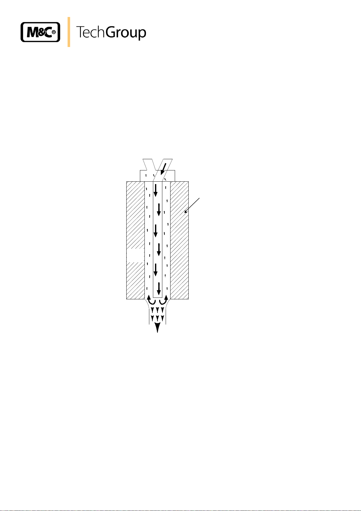
12 FUNCTION
The M&C EC-EX gas cooler is a compressor cooler with status alarm capability. This ensures 100%
availability of the cooler.
Up to 4 Jet-stream heat exchangers made of Borosilicate glass, PVDF or stainless steel are located in
a heat-insulated cooling block. All the heat exchangers are easily accessible and are arranged in such
a way that they can be removed very simply.
Figure 3 shows a schematic diagram of the functioning of the heat exchanger..
Figure 3 Functioning of heat exchanger
The compressor cooler system has a heat-insulated cooling block at a constant temperature of +5°C.
The novel construction of the heat exchanger guarantees a very good pre-separation of condensate
and for that reason an optimal drying of sample gas.
Alarm warnings for over- and under-temperature are given as a collective status alarm via a relay
output with two potential-free changeover contacts. Alarm will be released if the current temperature is
out of a range of 3°C referring to the set-temperature (+5°C).
Gas sampling and gas conditioning technology 3-4.1ME EC-EX 9904
Page 13

13
NOTE!
The cooler must be stored in a weatherproof frost-free area!
NOTE!
During transport and when in storage, the cooler must always be stood up
with the transport feet positioned underneath so that the oil in the closed
compressor circuit cannot run out of this compressor case. If the cooler is
transported on its back by mistake, it must stood in the operating position
for approx. 24 hours before it is switched on!
NOTE!
The compressor cooler EC-Ex is suitable for using in hazardous Group II
Category 2G. Attention must be paid to the certificate of conformity KEMA
03ATEX2113 (see appendix).
NOTE!
Please state the desired type of mounting when ordering so that the LED
function display can be positioned to match at the factory!
NOTE!
The operating position for this cooler is exclusively vertical. This is the
only way to ensure proper separation and removal of condensate in the
heat exchangers. During transport and installation, the cooler must
always be stood up with the transport feet positioned underneath so that
the oil in the closed compressor circuit cannot run out of the compressor
case.
The cooler should be kept away from sources of heat and well ventilated
when installed, so that condensation from warmth will not occur and
interfere with operation.
The minimum installation dimensions (fig. 2) must be followed without
fail. If the unit is installed in the open, the cooler must be installed in a
housing that is frost-free in winter and adequately ventilated In summer.
avoid locating the unit in direct sunlight.
Unheated gas sample lines must be provided with slope up to the cooler.
In that case pre-separation of the condensate is not required.
Connect the heated sample line with sufficient thermal decoupling to the
cooler!
13 RECEPTION AND STORAGE
The EC-EX gas cooler is a complete pre-installed unit.
Carefully inspect the cooler and any special accessories included with it immediately on arrival by
removing them from the packing and checking for missing articles against the packing list!
Check the items for any damage in transit and, if required, inform the shipping insurance company
immediately of the damage found!
14 INSTALLATION INSTRUCTIONS
The EC-EX cooler is equally suitable for wall mounting or for installation in a 19" rack.
Gas sampling and gas conditioning technology 3-4.1ME EC-EX 9904
Page 14

14
NOTE!
Do not mix up the hose connections; the inlet and outlet connections of the
heat exchangers are marked with arrows;
Ensure that the connections are sealed adequately;
To ensure free removal of the condensate, ensure that the listed diameters
for the condensate removal lines are not reduced!
NOTE!
When fixing the connectors in the PVDF heat exchanger hold up with a
wrench at the pane of the bolt head!
NOTE!
NOTE!
Stainless steel heat exchangers with G 3/8“ thread joint can be directly fitted
up with the float-type condensate trap AD-SS by means of a thread adapter
part number FF 11000 (1/2“ NPT to G 3/8“i). By this wall mounting of the AD-
SS unit isn’t necessary!
15 SUPPLY CONNECTIONS
15.1 HOSE CONNECTIONS
The hoses for the heat exchangers are laid out as per Figure 3.
The connection for sample gas inlet and outlet happens on the upper part of the heat exchangers. For
possible connectors see technical data (10.).
Correspondingly tube or hose connectors are optional available by M&C.
Ensure that the connections are sealed adequately by noting the following:
Borosilicate glass heat exchangers with connections GL 18-6 respectively GL 25-12
Before assembly, check the GL coupling rings to see if the PTFE/silicon locking rings have been
damaged.
The sealing rings should be installed with the PTFE side facing the medium.
To grant a functional and unproblematic mounting we recommend to use union pieces with taper
pipe thread type R according to DIN 2999/1 in connection with suitable sealing tape.
PVDF respectively stainless steel heat exchangers with G 1/4“i respectively G 3/8“i
The correspondingly dimensioned tube respectively hose couplings with threaded connections
have to be screwed in with PTFE thread sealing tape.
Option: stainless steel heat exchanger with NPT
The heat exchangers with NPT threaded connectors are marked with circulated notches.
The NPT thread must be screwed in with sealant or fixed with adhesive.
In the standard configuration, the tubes for removal of condensate are connected directly to the heat
exchangers. These protrude with the GL 25-12 tube connectors* (Borosilicate glass heat exchanger)
respectively with G 3/8“* thread joint (PVDF or stainless steel heat exchanger) above the base plate of
the cooler casing (Fig.2) (* standard).
Condensate removal is done by customer according to the type of operation with:
- Automatic float-type condensate traps AD-... only for over-pressure operation;
- Condensate collector container that is emptied manually;
- External peristaltic pump SR 25.1/Ex.
Gas sampling and gas conditioning technology 3-4.1ME EC-EX 9904
Page 15

15.2 ELECTRICAL CONNECTIONS
WARN I N G!
When connecting the equipment, please ensure that the supply
voltage is identical with the information provided on the model type
plate.
NOTE!
Attention must be paid to the requirements of IEC 364 (DIN VDE
0100) when setting high-power electrical units with nominal
voltages of up to 1000 V, together with the associated standards
and stipulations.
Check the details on the type plate to ensure that the equipment is
connected up to the correct mains voltage.
The main circuit must be equipped with a fuse of 10AT for the 230V
version and 16AT for the 115V version (automatic cut-out); for
electrical details see technical data.
Power supply : 230V/50Hz oder 115V/50-60Hz (see type plate)
Status alarm : one changeover contact
Contact rating : 230V AC, 2A, 100VA or
230V DC, 2A, 50W
Power
supply
2 N
3 PE
4
230V 50Hz
5
6
7
8
11 NC
12 Com
13 NO
Alarm
contact
230V 100VA
15
Figure 4 shows the electrical connections at the plastic housing behind the front panel of the EC-EX
casing (Fig. 2).
Figure 4 Electrical sockets
Gas sampling and gas conditioning technology 3-4.1ME EC-EX 9904
Page 16
16
Terminal
1 2 3
EC-EX Terminal box
Connection
L N PE
Terminal
11
12
13
EC-EX Terminal box
Connection
NC
COM
NO
NOTE!
If you want to connection this alarm contact, please remove the certified
stopping plug and install the enclosed certified cable gland. Certified cable
gland PTB-Nr. EX-90.C.1004 EEX eII must be used only, to maintain the EEx-e
class of protection.
NOTE!
Before starting up the gas cooler, it must be placed in its operating position
for at least two hours. The liquid inside the system may have been
redistributed, and this could cause problems in operating!
NOTE!
The status contacts must be connected to the external sample gas pump or
to a valve in the sample gas line to protect the entire analysis system by
immediately cutting off the gas supply in the event of error messages from
the cooler!
The power connection is in the terminal box inside the cooler housing
The potential-free contact of the status collector alarm is located as well in the terminal box inside the
EC-EX cooler housing.
Two PG 13.5 cable glands are provided for the cable bushings through the base plate of the cooler
casing.
The volt free contact output of the status group alarm is located on the same EEx-e terminal box.
16 START-UP
The automatic control electronics of the EC-EX permit automatic start-up of the cooler. The error
diagnostics guarantee full monitoring and reporting of possible sources of error.
The following description is valid for start-up of the gas cooler for an ambient temperature > 8°C.
The following steps should be carried out before initial start-up:
Connect the cooler unit to the mains power supply;
Check that the equipment is connected to the correct mains voltage, 115V or 230V, as shown on
the type plate!
Lead the status contacts for reporting of under- and over-temperature to the measuring station;
Gas sampling and gas conditioning technology 3-4.1ME EC-EX 9904
Page 17

17
°C >
ON
°C <
red
pink
green
°C >
ON
°C <
pink
green
16.1 FUNCTION SEQUENCE AND LED FUNCTION DISPLAY
Three function display LED's are provided to give a visualization of the function sequence during startup of the cooler. According to the type of installation, they are located either on the front panel or the
back panel of the cooler (Fig. 2). The top LED (red) indicates that the temperature set by the EC
automatic control electronics has been exceeded or has not been reached. The two-colour
(pink/green) LED in the middle shows that the cooler compressor is operating. The bottom red function
display LED gives an alarm if the temperature falls too low.
Switching the cooler on
As soon as there is a mains voltage, the top red LED lights up. This
indicates that the temperature of the cooler is above +8°C. The twocoloured LED in the middle lights up as pink once the cooler
compressor is in operation.
Normal operation
After around 30 minutes the cooler has been cooled down to a
temperature below +8°C. The top red LED goes out.
The status collector alarm contacts are deactivated and control the
automatic external release for gas measurement.
The cooler compressor is switched of as soon as the cooler stage
reaches the controlled temperature of +5°C. The middle LED lights up
as green.
The cooler compressor will be alternately switched on and off by the EC automatic control electronics
in a load-dependent cycle. The middle LED will alternately light up as pink and green (normal
operating functions).
Gas sampling and gas conditioning technology 3-4.1ME EC-EX 9904
Page 18

18
NOTE!
The location for the cooler must remain frost-free, even when the
unit has been switched off!
WARN I N G!
Aggressive condensate is possible.
Wear protective glasses and proper pretective clothing!
WARN I N G!
It is necessary to take the cooler off the mains before any
assembly, maintenance or repair work is carried out!
17 CLOSING DOWN
If the cooler unit is putting out of action for a short time no particular measures need to be taken.
We recommend sweeping the cooler with inert gas or ambient air while the unit is putting out of action
for a longer time.
18 MAINTENANCE
The safety instructions specific to the plant and process are to be consulted prior to any maintenance
work!
The EC-EX cooler unit does not require any special maintenance intervals.
Depending on the quality of the ambient air the cooling fin block should be blown out with compressed
air from time to time.
When using automatic condensate removal by means of peristaltic pumps, the hoses of the peristaltic
pumps must be checked every three or six months, depending on the operating conditions, and
replaced if necessary. The procedure for changing the hoses is given in the corresponding operating
instruction SR25.1/Ex (Appendix).
Gas sampling and gas conditioning technology 3-4.1ME EC-EX 9904
Page 19
19
NOTE!
Do not mix up the hose connections; gas outlet and gas inlet are marked
with arrows!
18.1 ADDING AND REPLACING THE HEAT EXCHANGERS
Removal of the heat exchangers may be necessary to carry out maintenance or repair work.
We recommend the following procedures and in this order for replacement of the heat exchangers:
Release the upper gas connections and lower condensate connections;
Pull the heat exchangers upwards with rotation out of the cooling block;
Replace the heat exchangers as follows:
Dry and clean the push-in opening in the aluminium cooling block with a cloth;
Smear the heat exchangers with a thin and equal layer over the whole surface with thermal
conductivity paste (part no. 90K0115) to ensure good conduction of heat. It is best to close off the
condensate removal of the heat exchangers tube with adhesive tape to prevent any of the thermal
conductivity paste from getting into the heat exchanger;
Lightly push the heat exchangers with rotation back into the push-in opening of the cooling block
and press to the upper block;
Remove the adhesive tape and any surplus thermal conductivity paste;
Reconnect the hoses.
Mounting the Borosilicate glass heat exchangers please notice:
Check the PTFE/Silicon locking rings for damage. in assembly, the locking rings must have the
PTFE side facing the medium, otherwise the required degree of sealing cannot be guaranteed!
Do up the red GL coupling rings hand-tight by turning them to the right;
Gas sampling and gas conditioning technology 3-4.1ME EC-EX 9904
Page 20

20
LED display
Function error
and status
alarm
Probable cause
Checking / Correction
°C >
ON
°C <
Equipment
does not cool;
No mains power;
Fuse F1
defective;
Check for main supply voltage 230V (115V)
at terminals X1.1 (L1) and X1.2 (N)
If O.K.:
check main supply voltage after fuse F1 on
control board in EEX-d box, if necessary
replace fuse. If O.K.: replace faulty control
board.
°C >
ON
°C <
red
pink
(red LED
V18 on
control board
is out)
Equipment does
not cool or
cooling is
insufficient;
Cooling
compressor is
not running;
Protective motor
switch M1.1
Compression
senor alarm S2
Temperature
sensor-alarm S1
First check the correct fit of the plugs in the
EEx-d box ( power supply for compressor )
If o.k.:
Check voltage in EEx-d box at terminals X2.7
(L) and X2.6 (N) (230V/115V) for compressor:
If 0 Volt on X2.6 and X2.7:
Either the protective motor switch M1.1 has
released and will switch on again after 3 min.
(this state can alternate; a possible reason is
that the ambient temperature or the needed
cooling power is to high) or the internal alarm
relays K1 has cut off because of temperatureor low pressure alarm:
1. Check compression sensor alarm S2.
Bridge over terminal X3.3 and X3.4. If
compressor runs, remove bridge and reset with
S2. (Possible reasons: very low ambient
temperature while starting the compressor or
empty cooling circuit).
Since September 2004 the pressure sensor
works without a reset switch. If the pressure
sensor releases the cooling aggregate is
potentially empty; please change the
aggregate
2. Check temperature sensor alarm S1.
Bridge over Terminal X3.5 and X3.6. If
compressor runs, remove bridge. After 10 min.
reset with S1. Otherwise renew defect EC-EX
control board.
19 TROUBLE SHOOTING
Troubleshooting is made much easier by the LED function display.
The following table shows possible reasons for error and how to correct them (not applicable for the
running-up phase of the cooler).
Gas sampling and gas conditioning technology 3-4.1ME EC-EX 9904
Page 21

21
LED display
Function error
and status
alarm
Probable cause
Checking / Correction
°C >
ON
°C <
red
pink
(red LED V18
on control
board is on)
Equipment does
not cool or
cooling is
insufficient;
see above
Cooling
compressor is
not running;
Cooling
compressor is
running; Cooler
is overstressed
1. Check voltage in the EEx-d box at terminals
X2.9 and X2.6 (N) (drive of the compressor
starting coil). In case of 230V (115V) renew the
EC-EX control board.
There is no voltage at terminals X2.9 and X2.6
(N):
2. Check the starting coil;
The red LED V18 must be light up. Check the
voltage at clamps X2.12 and X2.6. In case of
voltage change the control board or renew the
capacitors.
Note: If the compressor is stuck the described
stage (red LED V18 on) can alternate with the
above described stage (red LED V18 out),
because the protective motor switch will release
and switch on again after 3 min.
Check:
-Is gas flow 4 x 250 l/h maximum?
-Is ambient temp. +45°C maximum?
-Cooling fins are dirty?
Release EC-EX temperature sensor R51
at terminals X3.1+ X3.2 and measure
resistance.
It should be > 1.7 k at 20°C ambient temp.
If O.K.:
Replace complete EC-EX compressor unit
°C >
ON
°C <
green
red
or
°C >
ON
°C <
green
red
Equipment does
not cool;
Cooling
compressor
stopped;
Release EC-EX temperature sensor R51 at
X3.1 and X3.2 and measure resistance.
It should be >1.7 k at 20°C ambient temp.
If faulty:
fit new EC-EX temperature sensor to cooling
block using heat sink paste.
If o.k.:
Replace faulty EC-EX control board.
°C >
ON
°C <
red
pink
Cooler has been
over-cooled
(temp. < 2°C);
Cooling
compressor runs
to long or
continuously;
Release EC-EX temperature sensor R51 at
X3.1 and X3.2 and measure resistance.
Should be >1.7 k at 20°C ambient temp.
If faulty:
fit new EC-EX temperature sensor to cooling
block using heat sink paste.
If o.k.:
Replace faulty EC-EX control board
Gas sampling and gas conditioning technology 3-4.1ME EC-EX 9904
Page 22

22
20 EC AUTOMATIC CONTROL BOARD
Figure 5 shows the arrangement of the EC-EX automatic control board (wiring scheme in Appendix).
Figure 5 EC-EX automatic control board
Gas sampling and gas conditioning technology 3-4.1ME EC-EX 9904
Page 23

23
NOTE!
Do not adjust the temperature below +2°C or above +7°C.
Freezing-up of the heat exchanger can happen below +2°C.
Above +7°C the cooling unit will not work sufficiently!
20.1 TEMPERATURE SETTING FOR THE EC/ECS COOLER
The EC-EX gas cooler is set at the factory to a regulated temperature of +5°C.
Setting of the regulated temperature is done by trimming potentiometer P1, on the EC-EX automatic
control board of the cooler. The setting range covers from 0°C to 20°C. Turning it to the left sets a
lower temperature, and turning it to the right sets a higher temperature.
Figure 6 Temperature setting
Connecting an external temperature measuring device into the cooling block out of aluminium the real
temperature can be taken and controlled.
Gas sampling and gas conditioning technology 3-4.1ME EC-EX 9904
Page 24

24
21 CHECKING THE TEMPERATURE SENSOR
The temperature sensor of the EC-EX cooler is a KTY-semiconductor.
Figure 7 Temperature sensor resistance
Gas sampling and gas conditioning technology 3-4.1ME EC-EX 9904
Page 25

25
Electric gas cooler EC-EX
(C) consumable parts and (R) recommended spare parts
recommended quantity
EC-EX being in
operation [years]
Part number
Description
C/R 1 2
3
02 K 9105
EC-G jet stream heat exchanger
material: Borosilicate glass
R 1 1
1
02 K 9150
EC-G-90° jet stream heat exchanger
material: Borosilicate glass
R 1 1
1
02 K 9200
EC-SS jet stream heat exchanger
material: stainless steel
R 1 1
1
02 K 9250
EC-SS/NPT jet stream heat exchanger
material: stainless steel
Connections: sample gas in and out 1/4“i NPT
condensate out 3/8“i NPT
R 1 1
1
02 K 9300
EC-PV jet stream heat exchanger
material: PVDF
R 1 1
1
90 K 0115
EC thermal conductivity paste 50 g (-40°C to
140°C)
R 1 1
2
90 K 5010
EC-EX temperature sensor R51
E - -
1
90 K 5015
EC-EX Temperature contact S1
E - -
1
90 K 1010
EC-EX LED-display unit with connecting cable
E - -
1
90 K 5035
EC-EX cooling unit complete with compressor
vaporizer and condenser. Supply 230V, 50Hz
E - -
-
90 K 5040
EC-EX cooling unit complete with compressor
vaporizer and condenser. Supply 115 V, 50-60 Hz
E - -
-
90 K 5021
EC-EX control board complete with EEx-d box,
230V/50Hz
E - -
-
22 SPARE PARTS LIST
Wear, tear and replacement part requirements depend on specific operating conditions.
The recommended quantities are based on experience and are not binding.
Gas sampling and gas conditioning technology 3-4.1ME EC-EX 9904
Page 26

26
23 APPENDIX
Sample output dew point (ambient temperature 20°C) depending on gas flow rate
Circuit diagram EC-EX automatic control board 230V,
drawing number : 2392 - 5.04.0;
Circuit diagram EC-EX automatic control board 115V,
drawing number : 2392 - 5.05.0;
Certificate KEMA 03ATEX2113
More product documentation is available on our Internet catalogue:
www.mc-techgroup.com.
Instruction manual peristaltic pump SR 25.1,
Document : 3-7.1-MD;
Condensate vessel TG, TK
Document : 3-6.3.1
GL-connectors
Document : 3-5.1.1
Automatic liquid drain AD-SS
Document : 3-6.2.3
Automatic liquid drain AD-P
Document : 3-6.2.1
Gas sampling and gas conditioning technology 3-4.1ME EC-EX 9904
Page 27

27
Gasausgangs-Taupunkt
Sample outlet dewpoint
EC-G
10
5
187,5
125
250
°C
N l/h
Messgas-Durchfluss
Gas flow rate
Gasausgangs-Taupunkt
Sample outlet dewpoint
EC-SS
10
5
°C
N l/h
Messgas-Durchfluss
Gas flow rate
Gasausgangs-Taupunkt
Sample outlet dewpoint
EC-PV
10
5
°C
N l/h
Messgas-Durchfluss
Gas flow rate
62,5
187,5
125
250
62,5
187,5
125
250
62,5
60°C
40°C
Sample outlet dew point (ambient temperature 20°C) depending on gas flow rate
Sample input dew point
Figure 8 Sample outlet dew point
Gas sampling and gas conditioning technology 3-4.1ME EC-EX 9904
Page 28
28
Temperature sensor
Temperature contact
Compression contact
Schematic description of the EC-EX cooler including installation position of sensors
Figure 9 Schematic drawing
Gas sampling and gas conditioning technology 3-4.1ME EC-EX 9904
Page 29

29
Figure 10 Circuit diagram EC-EX 230V/50Hz
Gas sampling and gas conditioning technology 3-4.1ME EC-EX 9904
Page 30

30
Figure 11 Circuit diagram EC-EX 115V/50-60Hz
Gas sampling and gas conditioning technology 3-4.1ME EC-EX 9904
Page 31

31
Gas sampling and gas conditioning technology 3-4.1ME EC-EX 9904
Page 32

32
Gas sampling and gas conditioning technology 3-4.1ME EC-EX 9904
Page 33

33
Gas sampling and gas conditioning technology 3-4.1ME EC-EX 9904
 Loading...