

Page 1
Operating Manual
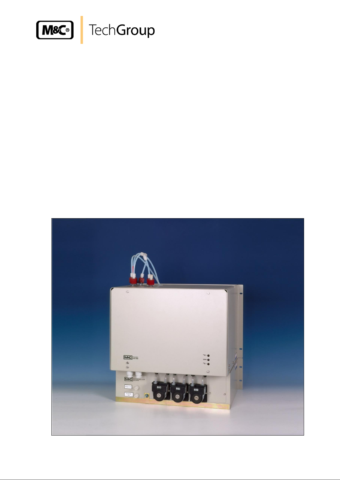
Low-temperature electric gas cooler series EC®
version EC30 and EC-30/FD
Gas sampling and gas conditioning technology 3-4.20-ME
Page 2

2
Content
1 General information ................................................................................................................... 5
2 Declaration of conformity .......................................................................................................... 5
3 Safety instructions ..................................................................................................................... 6
4 Warranty ...................................................................................................................................... 6
5 Used terms and signal indications ........................................................................................... 7
6 Introduction ................................................................................................................................ 8
6.1 Serial number ........................................................................................................................... 8
7 Application .................................................................................................................................. 9
8 Technical data .......................................................................................................................... 10
9 Description................................................................................................................................ 10
9.1 Assembly ................................................................................................................................ 11
10 Function .................................................................................................................................... 12
11 Reception and storage ............................................................................................................. 14
12 Installation instructions ........................................................................................................... 15
13 Supply connections ................................................................................................................. 15
13.1 Hose connections ................................................................................................................... 15
13.2 Electrical connections ............................................................................................................. 16
14 Start-up ..................................................................................................................................... 18
14.1 Function sequence and LED function display ........................................................................ 18
15 Closing down ............................................................................................................................ 20
16 Maintenance.............................................................................................................................. 20
16.1 Maintenance of the peristaltic pumps type SR25.1 of the EC-30/FD ..................................... 21
16.1.1 Change of the pump tube ................................................................................................. 21
16.1.2 Change of contact pulleys and springs ............................................................................. 22
16.1.3 Cleaning the pump head ................................................................................................... 22
16.2 Replacing the heat exchangers .............................................................................................. 23
17 Trouble shooting ...................................................................................................................... 24
18 EC automatic control board .................................................................................................... 26
18.1 Connecting the cooling compressor ....................................................................................... 27
18.2 Temperature setting for the cooler ......................................................................................... 28
19 temperature sensors ................................................................................................................ 28
19.1 Checking the temperature sensor of the pre-cooling stage .................................................... 28
19.2 Checking the temperature sensor of the deep cooling stage ................................................. 29
20 EC control board ...................................................................................................................... 31
20.1 Function sequence of the EC30 control electronics ............................................................... 32
21 Spare parts list ......................................................................................................................... 34
22 Appendix ................................................................................................................................... 35
Gas sampling and gas conditioning technology 3-4.20-ME
Page 3

3
List of Illustrations
Figure 1 Example of application of EC-30/FD .................................................................................. 9
Figure 2 EC-30 with options EC-F and EC-FD .............................................................................. 11
Figure 3 Schematic diagram of functioning of heat exchanger ...................................................... 12
Figure 4 Tubing of the heat exchangers ........................................................................................ 13
Figure 5 Timing schematic of the switching processes .................................................................. 13
Figure 6 Position of terminal X0 ..................................................................................................... 17
Figure 7 Electrical connections ...................................................................................................... 17
Figure 8 Change of the pump tube ................................................................................................ 21
Figure 9 EC automatic control board ............................................................................................. 26
Figure 10 Connection diagram for compressor ................................................................................ 27
Figure 11 Temperature adjustment .................................................................................................. 28
Figure 12 Voltage in relation to the temperature of the cooling stage ............................................. 29
Figure 13 Resistance-temperature characteristics of the PT100 temperature sensor ..................... 29
Figure 14 Sensor voltage as function of temperature ...................................................................... 30
Figure 15 EC30 control board .......................................................................................................... 31
Figure 17 Sample outlet dew point .................................................................................................. 36
Figure 18 Circuit diagram EC automatic control board .................................................................... 37
Figure 19 Circuit Diagram EC-30 ..................................................................................................... 38
Figure 20 Circuit diagram control electronic EC-30 ......................................................................... 39
Figure 21 Wiring plan automatic condensate removal unit EC-FD .................................................. 40
Gas sampling and gas conditioning technology 3-4.20-ME
Page 4

4
This Operating Manual does not claim completeness and may be
subject to technical modifications.
© 04/2000 M&C TechGroup Germany GmbH. Reproduction of this
document or its content is not allowed without permission from M&C.
3rd Edition: 11/2001
Dear customer,
we have made up this operating manual in such a way that all necessary information about the
product can be found and understood quickly and easily.
Should you still have any question, please do not hesitate to contact M&C directly or go through your
appointed dealer. Respective contact addresses are to be found in the annexe to this operating
manual.
Please also contact our homepage www.mc-techgroup.com for further information about our
products. There, you can read or download the data sheets and operating manuals of all M&C
products as well as further information in German, English and French.
Gas sampling and gas conditioning technology 3-4.20-ME
Page 5
5
Head Office
M&C TechGroup Germany GmbH Rehhecke 79 40885 Ratingen Germany
Telephone: 02102 / 935 - 0
Fax: 02102 / 935 - 111
E - mail: info@mc-techgroup.com
www.mc-techgroup.com
1 GENERAL INFORMATION
The product described in this operating manual has been examined before delivery and left our works
in perfect condition related to safety regulations. In order to keep this condition and to guarantee a
safe operation, it is important to heed the notes and prescriptions made in this operating manual.
Furthermore, attention must be paid to appropriate transportation, correct storage, as well as
professional installation and maintenance work.
All necessary information a skilled staff will need for appropriate use of this product are given in this
operating manual.
2 DECLARATION OF CONFORMITY
CE - Certification
The product described in this operating manual complies with the following EC directives:
EMV-Instruction
The requirements of the EC directive 2004/108/EC “Electromagnetic compatibility“ are met.
Low Voltage Directive
The requirement of the EC directive 2006/95/EC “Low Voltage Directive“ are met.
The compliance with this EC directive has been examined according to DIN EN 61010.
Declaration of conformity
The EU Declaration of conformity can be downloaded from the M&C homepage or directly requested
from M&C.
Gas sampling and gas conditioning technology 3-4.20-ME
Page 6

6
3 SAFETY INSTRUCTIONS
Please take care of the following basic safety procedures when mounting, starting up or
operating this equipment:
Read this operating manual before starting up and use of the equipment. The information and
warnings given in this operating manual must be heeded.
Any work on electrical equipment is only to be carried out by trained specialists as per the regulations
currently in force.
Attention must be paid to the requirements of VDE 0100 (IEC 364) when setting high-power electrical
units with nominal voltages of up to 1000 V, together with the associated standards and stipulations.
Check the details on the type plate to ensure that the equipment is connected to the correct mains
voltage.
Protection against touching dangerously high electrical voltages:
Before opening the equipment, it must be switched off and hold no voltages. This also applies to any
external control circuits that are connected.
The device is only to be used within the permitted range of temperatures and pressures.
Check that the location is weather-protected. It should not be subject to either direct rain or moisture.
The device must not be used in hazardous areas.
Installation, maintenance, monitoring and any repairs may only be done by authorized personnel with
respect to the relevant stipulations.
4 WARRANTY
If the equipment fails, please contact M&C directly or else go through your M&C authorised dealer.
We offer a one year warranty as of the day of delivery as per our normal terms and conditions of sale,
and assuming technically correct operation of the unit. Consumables are hereby excluded. The terms
of the warranty cover repair at the factory at no cost or the replacement at no cost of the equipment
free ex user location. Reshipments must be send in a sufficient and proper protective packaging.
Gas sampling and gas conditioning technology 3-4.20-ME
Page 7
7
DANGER!
This means that death, severe physical injuries and/or important
material damages will occur in case the respective safety measures
are not fulfilled.
W A R NI N G !
This means that death, severe physical injuries and/or important
material damages may occur in case the respective safety
measures are not fulfilled.
CARE!
This means that minor physical injuries may occur in case the
respective safety measures are not fulfilled.
CARE !
Without the warning triangle means that a material damage may
occur in case the respective safety measures are not met.
ATTE N T I O N !
This means that an unintentional situation or an unintentional status
may occur in case the respective note is not respected.
NOTE!
These are important information about the product or parts of the
operating manual which require user’s attention.
SKILLED STAFF
These are persons with necessary qualification who are familiar with
installation, use and maintenance of the product.
5 USED TERMS AND SIGNAL INDICATIONS
Gas sampling and gas conditioning technology 3-4.20-ME
Page 8

8
6 INTRODUCTION
The patented M&C EC30 gas cooler with universal unit EC-F and EC-30/FD with unit EC-FD is always
to be installed in situations where there is interference from moisture in the gas to be measured, or if
the measured components exhibit very high sensitivity to water vapour or if long and expensive heated
sampling lines are to be avoided.
Reduction of the gas temperature inside the cooler to a stable and very low dew point effects a
condensing out of the sample gas. Dry gas leaves the gas cooler and passes into the analyser after
suitable filtration. When installing the EC30(/FD) gas cooler on site in a frost-free protective housing,
there is no need to use a heated sample line with a high energy consumption as long as the ambient
temperature does not fall below a value of -25C.
6.1 SERIAL NUMBER
The type plate with the serial number is located at the side panel of the cooler housing (19“ version).
Whenever you call M&C regarding questions or orders for the spares please give us the serial number
of your EC30.
Gas sampling and gas conditioning technology 3-4.20-ME
Page 9
9
1
EC-
Sample gas IN
Sample
gas OUT
EC-30
Condensate
OUT
Test gas
IN
7 APPLICATION
The patented M&C ultra-low temperature cooler EC-30(/FD) finds its applications in the analytical field
for reducing the dew point of humid sample gases, providing a stable and very low dew point and
reducing aerosol formation in the analyser. By mounting the cooler near to the sample point, costly
energy consuming heated sample lines can be avoided. An extremely stable and low gas dew point
avoids water vapour cross-sensitivity and volumetric errors.
Figure 1 shows a typical example of an application for installation of an EC-30 gas cooler unit.
Filter sample probe SP... Universal unit EC-FD Membrane pump Analyser
Heated sample line 3-way-ball valve Flow meter FM
EC-30/FD cooler Super-fine filter FP... Aerosol filter CLF
Deep cooling stage 1 Deep cooling stage 2 Pre cooling stage
Figure 1 Example of application of EC-30/FD
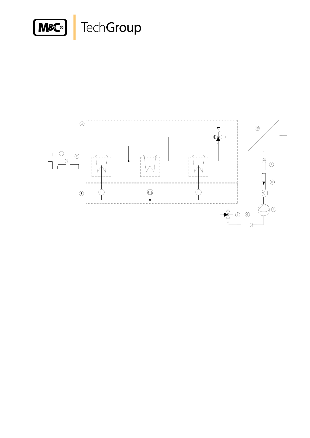
The gas to be measured is taken from the EC-30/FD gas cooler by a gas sample probe and
cooled down to a dew point of -30°C. Via the universal unit EC-FD the condensate is removed. The
super-fine filter located afterwards removes solid particles. For increased operating safety of the
entire system we recommend installing a super-fine filter with a liquid alarm sensor. If required an
aerosol filter can be installed in front of the flow meter . The gas thus treated can now be passed
into the analyser . Via the 3-way-ball valve it is possible to feed test gas for calibration to the
analyser.
Gas sampling and gas conditioning technology 3-4.20-ME
Page 10
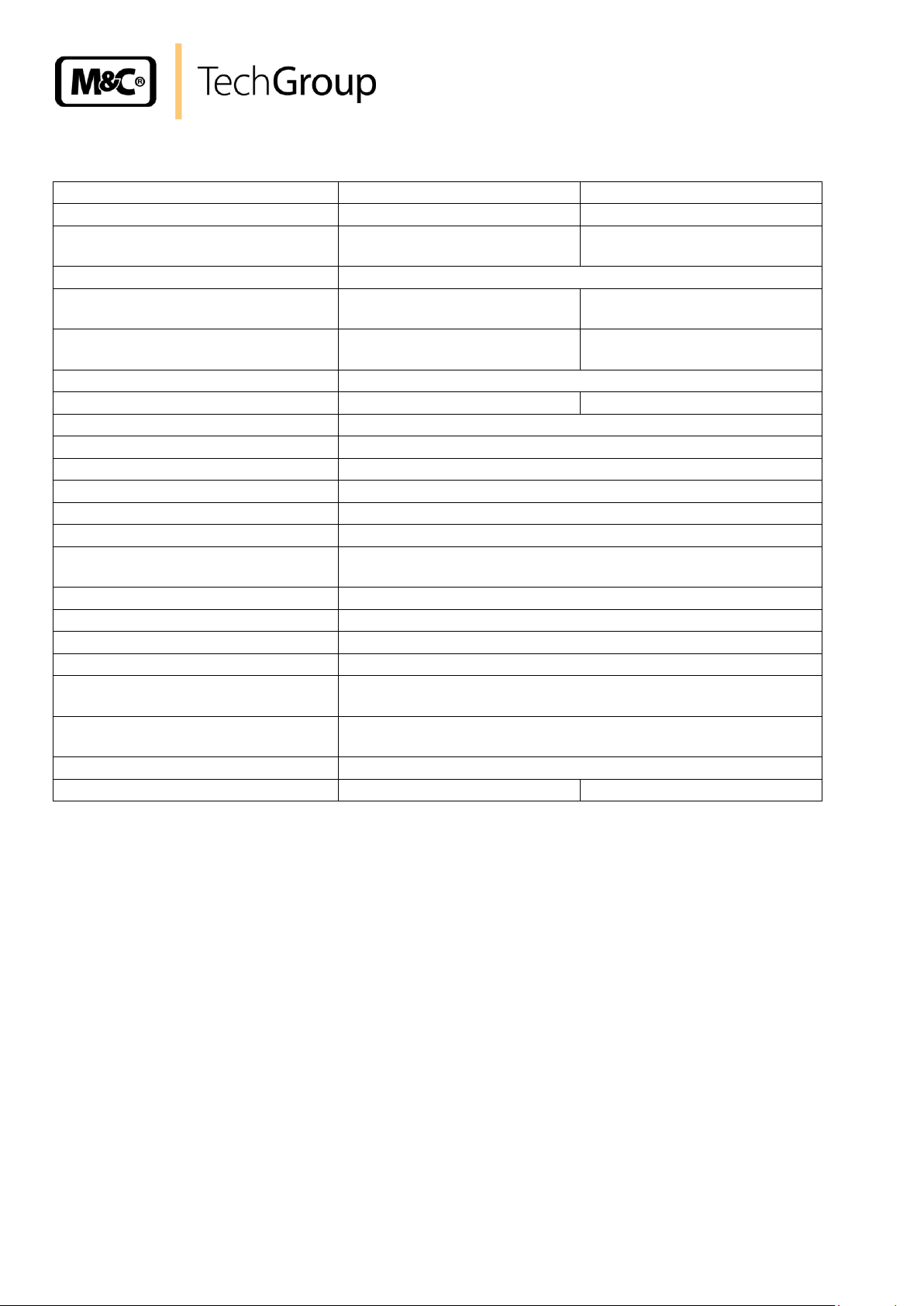
8 TECHNICAL DATA
Cooler series EC®
Version EC-30
Version EC-30/FD
Part No.
02K6000 (a)**
02K6010 (a)**
With integrated universal unit:
EC-F to force the ventilation
EC-FD ventilation and
condensate removal
Gas connection
tube connector DN 4/6 i./o. d. mm
Condensate connections
3x tube connector GL25-12 mm
1x tube connector DN 4/6 i./o. d.
mm
Material of sample contacting parts
Duran glass, PTFE, PVDF
Duran glass, PTFE, PVDF,
Novoprene
Single stream, gas flow rate
90 Nl/hr-250 Nl/hr*
Gas pressure
max. 3 bar abs.
max. 2 bar abs.
Ambient temperature
+5 to +45 °C
Storage temperature
-20 to +60°C
Sample outlet dew point
-30 °C
Sample inlet temperature
max. 180 °C*
Sample inlet dew point
max. 80 °C*
Cooling capacity at 25 °C ambient
max. 860 kJ/hr*
Main power connection / Power
consumption
230V 50Hz 380VA or **Part No. ...-a = 115V 60 Hz 380VA
Start up time
< 60 min.
Stagnant space
approx.160 ml
Δ P at 250 Nl/hr flow rate
5 mbar
Electrical connection
2,5 mm2 terminals, 2x PG13,5 cable glands
Status alarm
2 changeover contacts, potential free contact rating 250V, 3A,
500VA, 50W
Case protection / Electrical equipment
standard
IP20 EN 60529 / EN 61010
Method of mounting / Case colour
19" rack or wall / case colour RAL 9003
Dimension / Weight
84 TE x 8 HE x 360 mm / 37 kg
84 TE x 10 HE x 360 mm / 42 kg
10
** Maximum values in technical datas must be rated in consideration of total cooling capacity at 25 °C ambient temperature and an outlet
dew point of 5 °C.
9 DESCRIPTION
The patented M&C gas cooler EC-30(/FD) is a two stage combination of compressor and Peltier
cooler with status alarm and automatic defrosting of the dual deep freezer unit for 100% sample
availability. The pre-cooler of the gas cooler EC- is fitted with a “Jet-Stream“ heat exchanger EC-G
which is cooled by a compressor cooling unit with electronic control at a constant temperature of +1°C.
Optimum cooling of sample gases and pre-elemination of a larger part of the condensate from the gas
is reliably achieved. No external pre-draining is normally needed. The deep freezer and is cooled
with two modified “Jet-Stream“ heat exchangers EC-30 fitted between two automatic cooling units for a
minimum temperature of -30 °C. The special design of the Jet-Stream heat exchanger guarantees
optimum dew point reduction to a low, stable value and secures condensate separation. The gas
outlets of the heat exchangers are connected to a 3/2 way solenoid valve. An electronic control system
EC-30 switches the solenoid valve for simultaneous changeover and automatic defrosting of the heat
exchangers EC-30. In order to guarantee the necessary and minimum operation of the gas cooler EC30, we provide this unit with an accessory module EC-F containing two fans for forced air ventilation
and cooling of the compressor unit. Alternative we deliver the cooler with the module EC-FD
containing additionally three peristaltic pumps SR-25.1 for automatic removal of condensate.
Gas sampling and gas conditioning technology 3-4.20-ME
Page 11

9.1 ASSEMBLY
11
Figure 2 EC-30 with options EC-F and EC-FD
Gas sampling and gas conditioning technology 3-4.20-ME
Page 12
12
+5°C
Sample gas
out
Sample gas
in
Condensate out
Coolingblock
The EC30 is equally suitable for wall installation or mounting in a 19” rack. The versions differ in the
positioning of the LED function display . While for wall installation the LED function display can be
fitted into the corresponding cut-outs in the EC30 front panel, for 19” rack mounting this is done using
the cut-outs in the back panel of the casing. This positioning is done at the factory when stating the
type of installation of the EC30 gas cooler. It is relatively simple to subsequently reconfigure it on site
at the user location. The location for installation of the LED function display is marked
correspondingly.
On the upper side of the cooler casing you will see the cut-outs for the heat exchangers of the precooling stage and for the two low-temperature stages and . Sample gas enters the pre-cooling
stage at the 4/6 hose connection on the upper part of the heat exchanger. At the rear part of the
casing the condenser to remove heat given off in the compressor can be seen. The mains power
connector, EC automatic control board and EC30 control board with the contact outputs for the status
alarm are located in two plastic housings respectively behind the removable front panel of the EC30
casing.
On the underside of the casing the following connections are provided as standard: cable glands
PG13,5 to the plastic housings ; condensate outlets GL25/12 from the heat exchangers ,
and ; sample gas outlet DN4/6.
As standard, the condensate is removed externally with collecting vessels, peristaltic pumps, or by
”over-pressure operation”, with automatic float condensate traps, as e.g. type AD-... The heat energy
from the cooling system is drawn off by a forced-ventilation . The required fans and large air
suction filter elements are provided as standard in universal unit EC-f . This is arranged below the
EC30 casing and is absolutely essential for operation of the cooler unit. Optionally, the universal unit
EC-F can be replaced by an automatic condensate removal unit EC-FD , which is likewise located
below the casing of the cooler. Apart from the above-mentioned condenser forced ventilation, the ECFD unit has three peristaltic pumps of type SR25.1 for automatic condensate removal. This can also
be set in underpressure operation (suction operation).
The connections for the sample gas outlet and the condensate outlet are located in the front
panel of the EC-FD unit.
10 FUNCTION
The patented M&C EC30(/FD) gas cooler is a combined two stage compressor Peltier cooler with
status alarm capability. Automatic defrosting of the double-construction low temperature stage ensures
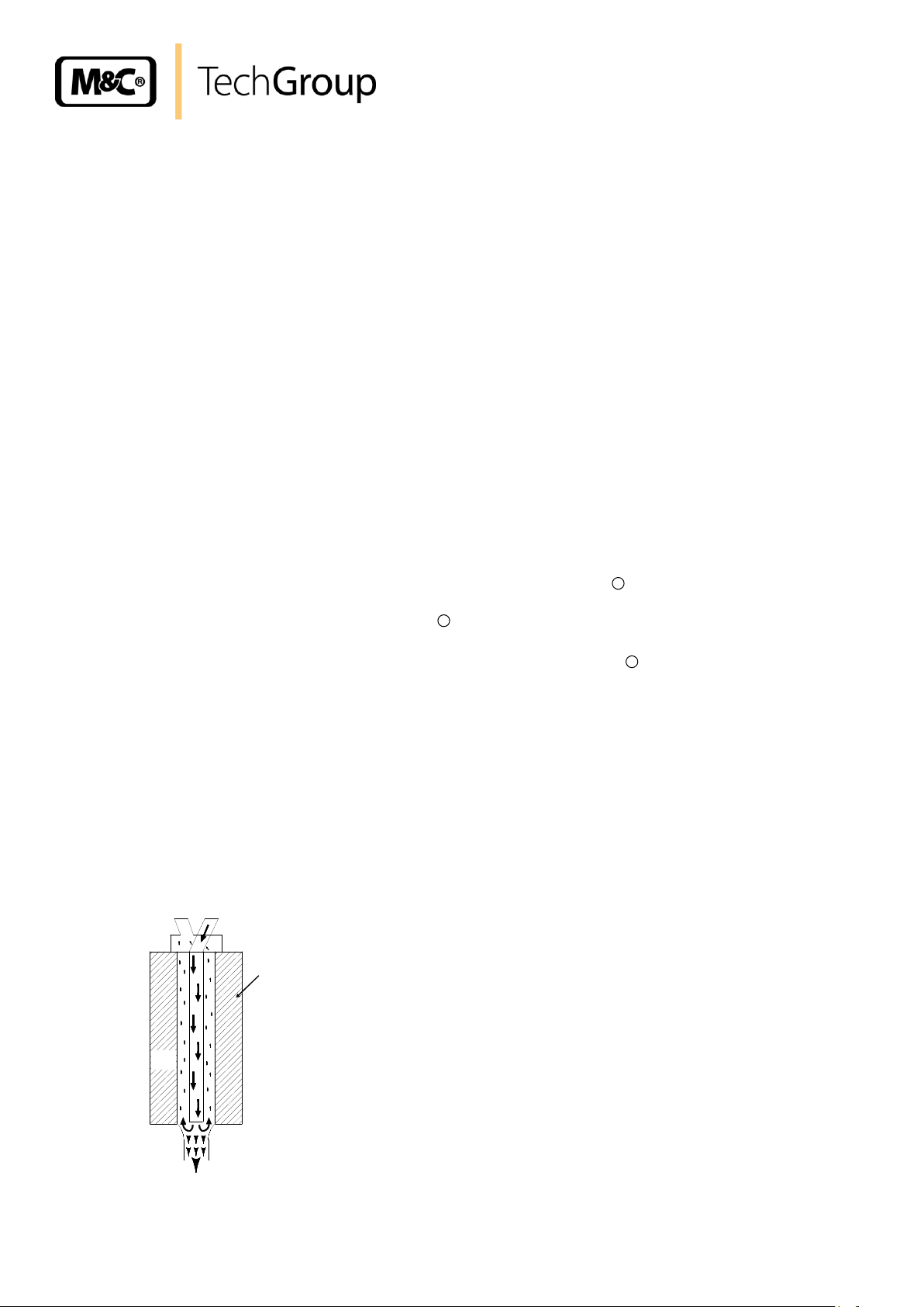
100% availability of the cooler. The pre-cooling stage (see fig. 1) of the cooler is equipped with a jet
stream EC heat exchanger made of Duran glass. Figure 3 shows a schematic diagram of the
functioning of the heat exchanger.
Figure 3 Schematic diagram of functioning of heat exchanger
Gas sampling and gas conditioning technology 3-4.20-ME
Page 13

13
Solenoid valve
Channel 2
Channel 1
Temperature channel 2
Temperature channel 1
EC pre-cooler
Ambient temperature
Power OFF
Power ON, start
1 hr
3 hr
3 hr
3 hr
3 hr
Status
o.k.
Alarm
-30°C
+5°C
-30°C
+5°C
+1°C
Sample gas
IN
Sample gas
OU
Pre-cooling stage
Deep cooling stages
A decoupled compressor cooler system has a heat-insulated cooling block at a constant temperature
of +1C. Control of the compressor is contactless done by the EC automatic control electronics and is
therefore not subject to wear. The pre-cooling stage ensures that the greater part of the condensate
has already been removed from the gas stream.
The low-temperature stages are provided with two modified jet stream EC30 heat exchangers made of
Duran glass. These are cooled down to a temperature of around -30C by two completely independent
Peltier element cooling systems.
Stages and (see fig. 1) of the gas cooler work intermittently at intervals of three hours. While one
stage is in operation, the other one is automatically defrosted. All the heat exchangers are easily
accessible and are arranged in such a way that they can be removed very simply. Switching over the
gas flow is done by a 3/2-way solenoid valve made of PVDF/Viton (see fig. 4). This arrangement
excludes any possibility of water vapour being sucked back from the low-temperature stage that is
being defrosted.
Figure 4 Tubing of the heat exchangers
The EC30 control electronic switches the solenoid valve every three hours and at the same time
carries out the alternating defrosting process of the low-temperature heat exchangers.
Figure 5 Timing schematic of the switching processes
Gas sampling and gas conditioning technology 3-4.20-ME
Page 14
14
NOTE!
The cooler must be stored in a weather-protected frost-free area!
NOTE!
During transport and when in storage, the cooler has always to stand vertical
with the transport feet positioned underneath so that the oil in the closed
compressor circuit cannot run out of this compressor case. If the cooler is
transported on its back by mistake, it has to stand in the operating position
for approx. 24 hours before it is switched on!
The heat energy from the cooling system is drawn off by the forced ventilated condenser. The LED
function display on the front of the cooler shows the operating status. Alarm warnings for over- and
under-temperature are given as a collective status alarm via a relais output with two potential-free
changeover contacts.
11 RECEPTION AND STORAGE
The EC-30(/FD) gas cooler is a complete pre-installed unit.
Carefully inspect the EC-30(/FD) and any special accessories included immediately on arrival by
removing them from the packing and checking for missing articles against the packing list!
Check the items for any damage in transit and, if required, inform the shipping insurance
company immediately of the damage found!
The tubing for the heat exchangers is dismounted for shipping and it is separately inside of the
package.
Gas sampling and gas conditioning technology 3-4.20-ME
Page 15

15
NOTE!
Please state the desired type of mounting when ordering, so that the LED
function display can be positioned to match at the factory!
NOTE!
The operating position for this cooler is exclusively vertical. This is the only
way to ensure proper separation and removal of condensate in the heat
exchangers. During transport and when in storage, the cooler has always to
stand vertical with the transport feet positioned underneath so that the oil in
the closed compressor circuit cannot run out of this compressor case.
The cooler should be kept away from sources of heat and well ventilated
when installed, to avoid interfering heat accumulation.
The minimum installation dimensions (fig. 2) must be followed without fail. If
the unit is installed outdoors, the cooler must be installed in a housing that
is frost-free in winter and adequately ventilated in summer. Avoid locating
the unit in direct sunlight.
Unheated gas sample lines have to be run with slope up to the cooler. In that
case pre-separation of the condensate is not required.
Connect the heated sample line with sufficient thermal decoupling to the
cooler!
NOTE!
Do not mix up the hose connections; the inlet and outlet connections of the
heat exchangers are marked with arrows;
Exit hose of the low-temperature stage (fig. 4) is marked red.
Ensure that the connections are sealed adequately;
To ensure free removal of the condensate, ensure that the listed diameters
for the condensate removal lines are not reduced!
12 INSTALLATION INSTRUCTIONS
The EC-30(/FD) cooler is equally suitable for wall mounting or for installation in a 19" rack.
13 SUPPLY CONNECTIONS
13.1 HOSE CONNECTIONS
The hoses for the heat exchangers are connected as shown in figure 4.
Ensure that the connections are sealed adequately by noting the following:
Duran glass heat exchangers with GL connections
Before assembly, check the GL coupling rings to see if the PTFE/silicon locking rings have been
damaged;
The locking rings should be installed with the PTFE side facing the medium.
PVDF heat exchangers with PVDF tube connectors
Carefully remove the nuts from the coupling body so that the ferrule that is loose inside the nut
will not be lost.
Push the union nut first, and then the ferrule with the thick bulb facing the nut, onto the 4/6 mm
hose.
Push the hose onto the support nipple in the coupling body and tighten the union nut hand-tight.
Gas sampling and gas conditioning technology 3-4.20-ME
Page 16

16
NOTE!
When fixing the connectors in the PVDF heat exchanger hold up with a
wrench at the pane of the bolt head!
The connection for the gas inlet (see above) is made to the heat exchanger
of the pre-cooling stage 3(fig. 2). This is marked accordingly with an arrow.
The outlet for gas to be measured, DN 4/6, is located as standard on the
universal unit EC-F located on the underside of the cooler casing (fig. 2).
When using the automatic condensate removal EC-FD, the connection for
the outlet for gas to be measured will be made to the corresponding
connector on the front panel of the universal unit (fig. 2).
W A R NI N G !
When connecting the equipment, please ensure that the supply
voltage is identical with the information provided on the model
type plate.
NOTE!
Attention must be paid to the requirements of IEC 364 (DIN VDE
0100) when setting high-power electrical units with nominal
voltages of up to 1000 V, together with the associated standards
and stipulations.
Check the details on the type plate to ensure that the equipment is
connected up to the correct mains voltage.
The main circuit must be equipped with a fuse of 10AT (over
current protection); for electrical details see technical data.
In the standard configuration, the tubes for removal of condensate are connected directly to the heat
exchangers.
These protrude with the 12mm tube connectors above the base plate of the cooler casing (fig. 2).
Condensate removal is done according to the type of operation with:
Universal unit EC-FD with peristaltic pumps for automatic condensate removal;
Automatic float condensate trap and remover AD-... only for over-pressure operation;
Condensate collector container that has to be drained manually.
13.2 ELECTRICAL CONNECTIONS
Gas sampling and gas conditioning technology 3-4.20-ME
Page 17

17
123456789
10
NCMCNONCMCNOPENL
X0
Power connection to
EC electronics
Alarm connection to
EC electronics
Power In
by customer
Alarm connection by
customer
EC-electronic
Pre-cooler
EC30-electronic
deep
EC30 power supply
Terminal X0
Solenoid valve
Sample gas switching
from deep
cooling stage
from deep
cooling stage
2 x PG 13,5
Figure 6 shows the location of the terminal X0 behind the front panel of the EC-30 casing (fig. 2).
Power supply : 230V/50Hz or 115V/60Hz (see type plate)
Status alarm : two potential free changeover contacts
Contact rating : 250V AC, 2A, 500VA or
250V DC, 2A, 50W
Figure 6 Position of terminal X0
Two PG 13,5 cable glands are provided for the cable bushings through the base plate of the cooler
casing. Power and alarms have to be connected as shown in the pin configuration in Figure 7 below:
Figure 7 Electrical connections
Gas sampling and gas conditioning technology 3-4.20-ME
Page 18

18
NOTE!
Before starting up the gas cooler, it must be placed in its operating position
for at least two hours. The liquid inside the system may has been
redistributed, and this could cause problems in operating!
NOTE!
The status contacts must be connected to the external sample gas pump or
to a valve in the sample gas line to protect the entire analysis system by
immediately cutting off the gas supply in the event of error messages from
the cooler!
°C >
ON
°C <
red
pink
green
14 START-UP
The control electronics of the EC30(/FD) permit automatic start up of the cooler, which also ensures
safe and guaranteed operation regardless of external influences such as a power failure. The error
diagnostics guarantee full monitoring and reporting of possible sources of error. The following
description is valid for startup of the gas cooler for an ambient temperature > 5C.
The following steps should be carried out before initial start up:
Connect the cooler unit to the mains power supply; Check that the equipment is connected to
the correct mains voltage, 115V or 230V, as shown on the type plate.
Lead the status contacts for reporting of low- and excess temperature to the measuring station.
14.1 FUNCTION SEQUENCE AND LED FUNCTION DISPLAY
Three function display LEDs are provided to give a visualization of the function sequence during start
up of the cooler. According to the type of installation, they are located either on the front panel or the
back panel of the cooler (fig. 2). The top LED (red) indicates that the temperature set by the EC
automatic control electronics for the pre-cooler stage has been exceeded or has not been reached.
The two-colour (pink/green) LED in the middle shows that the cooler compressor is operating (on/off).
The bottom red function display LED gives an alarm if the pre-cooler stage temperature falls too low or
if the low-temperature stage temperature is exceeded.
Switching the cooler on
As soon as there is a mains voltage, the top red LED lights up. This
indicates that the temperature of the pre-cooler is min. 3C above the set
temperature of +1C. The two-coloured LED in the middle lights up as pink
once the cooler compressor is in operation.
Gas sampling and gas conditioning technology 3-4.20-ME
Page 19

19
NOTE!
A second meaning of the flashed up bottom red LED and the flashed up
green LED in the middle could be that the temperature of the pre-cooling
stage is to low (see also chapter 17).
°C >
ON
°C <
pink
green
red
°C >
ON
°C <
pink
green
Switching on the low-temperature stages
After approx. 30 minutes the pre-cooler stage has been cooled down to a
temperature below +4C. The top red LED goes out and the bottom red LED
lights up. The low-temperature stage is activated and starts operating at
full power. The cooler compressor is switched of as soon as the pre-cooler
stage reaches the controlled temperature of +1C. The middle LED lights up
green. The cooler compressor will be alternately switched on and off by the
EC automatic control electronics in a load-dependent cycle. The middle LED
will alternately light up pink and green (normal operating functions).
Normal operation
After about 1 hour the low-temperature stage reaches the alarm threshold
value of -25C. The bottom LED goes out. The status collector alarm
contacts are deactivated and control the automatic external release for gas
measurement. The EC30 cooler unit is ready for operation. The low
temperature stage will be operated without control and will reach approx. 30C. Normal operating function will be indicated on the front panel by the
middle two-coloured LED.
Gas sampling and gas conditioning technology 3-4.20-ME
Page 20

20
NOTE!
The location for the cooler must remain frost-free, even when the
unit has been switched off!
W A R NI N G !
Aggressive condensate is possible.
Wear protective glasses and proper protective clothing!
W A R NI N G !
Dangerous voltage!
Before opening the housing please disconnect the cooler from the
mains supply!
15 CLOSING DOWN
If the cooler unit is put out of operation for a short time no particular measures have to be taken.
We recommend purging the cooler with inert gas or ambient air, while the unit is put out of operation
for a longer time.
16 MAINTENANCE
The safety instructions specific to the plant and process are to be consulted prior to any maintenance
work!
The EC-30(/FD) cooler unit does not require any special maintenance intervals.
Depending on the degree of contamination of the ambient air the cooling fins of the condenser have
to be cleaned periodically with pressure air and the air suction filter units in the EC-F / EC-FD
universal unit have to be cleaned or replaced. They are located in a plug-in box underneath the
cooler unit. The filter elements are removed as follows:
Unclamp the plug-in box by turning the quick-lock screw plug 90to the left;
Pull out the box;
Remove the crossbars holding the filter element by pulling with moderate force in the direction
of the filter element axis;
Remove and replace the filter elements.
Reassembly is done in the reverse order.
Gas sampling and gas conditioning technology 3-4.20-ME
Page 21

21
DANGER
Dangerous voltage!
It is necessary to take the pump off the mains before any assembly,
maintenance and repair work is carried out!
CARE!
Aggressive condensate is possible!
Wear protective glasses and proper protective clothing!
NOTE!
If you send back the peristaltic pump to the M&C service for repair,
please let us know what kind of condensate has been pumped.
Before sending the pump back clean all parts from dangerous or
highly aggressive contaminants.
1
2
3
4
16.1 MAINTENANCE OF THE PERISTALTIC PUMPS TYPE SR25.1 OF THE EC-30/FD
Before the maintenance work is carried out, it is necessary that the specific safety procedures
pertaining to the system and operational process are observed!
Flexible tube, conveying belt, contact pulleys and contact springs are the only parts of the pump
subject to wear. They are easy to change.
16.1.1 CHANGE OF THE PUMP TUBE
Figure 8 Change of the pump tube
Take off the cooler of the mains;
Open hose connectors at the pump;
Press conveying belt at the recessed grips and turn S-bolt clockwise up to limit stop;
Gas sampling and gas conditioning technology 3-4.20-ME
Page 22

22
NOTE!
Only the usage of the original hose set guarantees a perfect function.
Never lubricate the hose.
Before mounting the pump check all parts for impurity and clean if
necessary.
NOTE!
While mounting pay attention to the fit of ‘rotational axis - driver’.
Use genuine spare parts only!
CARE!
Aggressive sample is possible!
Wear protective glasses and proper protective clothing during
disassembly, repair or cleaning!
Take away conveying belt and remove the old hose set from the guides by the hose
connectors;
Press the two contact pulleys and check whether the spring pressure is still sufficient, if not,
the contact springs have to be changed;
Put the new hose set with the hose connectors into the guides of the conveying belt ;
Put the conveying belt with the new hose into the dovetail guide of the pump body;
Press conveying belt at the recessed grips and simultaneously turn the S-bolt anticlockwise
until it snaps;
Switch on pump.
16.1.2 CHANGE OF CONTACT PULLEYS AND SPRINGS
Take off the cooler of the mains;
Unscrew the nut of the pump head (span of the jaw 5,5);
Draw the pump head out of the motor shaft; Now the driver can be taken out of the pump head
and is ready for maintenance.
To remove the springs (4 pcs.) of the driver is possible without the aid of any tools. Therefore
press the spring together and take it out of the groove in the driver respectively out of the
boring in the axle. Now the roller bearing axle can be dismounted and the contact pulleys are
ready for change.
Remounting in reverse order.
16.1.3 CLEANING THE PUMP HEAD
When changing flexible tube or other parts, inspect all parts for dirt before assembling the
pump head and clean them if necessary.
Clean the parts with a dry cloth as far as possible. Solvents should not be used as they can
attack the plastics and synthetic rubber parts. If a compressed air line is available, blow out the
parts with pressure air.
Gas sampling and gas conditioning technology 3-4.20-ME
Page 23

23
NOTE!
Do not mix up the hose connections; the outlet hose for the low temperature
stage is marked in red!
16.2 REPLACING THE HEAT EXCHANGERS
Removal of the heat exchangers may be necessary to carry out maintenance or repair work. It is
possible to replace the heat exchanger (pre-cooling stage) without switching off the entire cooler.
This does not apply to the heat exchangers of the low-temperature stages and . Icing-up at
operating temperatures of -30C will make it impossible to dismantle the unit. It will take approximately
two hours to defrost after switching off the cooler. We recommend the following procedures for
replacement of the heat exchangers in the following order:
Release the GL coupling rings by turning them to the left at the upper gas connections and
lower condensate connections to the glass heat exchangers;
Pull the heat exchangers upwards with rotation out of the cooling block;
Dry and clean the push-in opening in the aluminium cooling block with a cloth;
Smear thermal conductivity paste (part no. 90K0115) on the heat exchangers with a thin and
equal layer over the whole surface to ensure good conduction of heat. It is best to shut the
condensate outlet of the heat exchangers with adhesive tape to prevent any of the thermal
conductivity paste from getting into the heat exchanger;
Lightly push the heat exchangers back into the opening of the cooling block and press to the
upper limit stop;
Remove the adhesive tape and any surplus thermal conductivity paste;
Reconnect the hoses as shown in the flow diagram (fig. 4).
Check the PTFE/Silicon locking rings for damage. In assembly, the locking rings must have the
PTFE side facing the medium, otherwise the required degree of sealing cannot be guaranteed!
Screw on the red GL coupling rings hand tight by turning them to the right.
Gas sampling and gas conditioning technology 3-4.20-ME
Page 24

24
LED display
Function error
and status
alarm
Probable cause
Checking / Correction
°C >
ON
°C <
Equipment
does not cool;
No mains power;
Check the mains voltage 230V (115V) at terminal X0
(see Fig. 6 and 7);
If mains voltage OK:
replace defective EC automatic control board.
°C >
ON
°C <
red
pink
Equipment does
not cool or the
cooling is
insufficient;
Cooling compressor is not running;
Check that the plugs are firmly seated in the sockets
for power connection to the compressor;
If OK:
Measure the voltage 230V/115V for the compressor
at the EC automatic control board at pins 21 and 22
(see Fig. 9).
If not OK:
Replace the defective EC automatic control board;
If OK:
Does the red LED D3 (see Fig. 9) on the EC
automatic control board lights up for more than one
second?
(A blocked unit will be switched off by the motor
breaker switch);
If yes:
Replace the starting condenser;
If compressor does not run:
Send cooler in for repair.
°C >
ON
°C <
red
pink
See above
Cooling compressor runs; over-loading of the cooler
unit;
Check:
- Is the maximum of 250 l/hr of gas flowing?
- Is the ambient temperature max. +45°C?
- Are the air suction filters dirty?
- Are the fans working?
- Are the condenser fins contaminated?
If OK:
Check temperature at the EC automatic control
board (18.2);
If the temperature is < 4°C (< 0,4V) for a nominal
set temperature of +1°C:
Replace EC automatic control board;
If temperature > 4°C (>0,4V):
Check PT100 temperature sensor (19.1);
If not OK:
Replace sensor;
If sensor and electronics OK:
Send cooler in for repair.
17 TROUBLE SHOOTING
Troubleshooting is made much easier by the LED function display.
The following table shows possible reasons for error and how to correct them (not applicable for the
running-up phase of the cooler).
Gas sampling and gas conditioning technology 3-4.20-ME
Page 25

25
LED display
Function error
and status
alarm
Probable cause
Checking / Correction
°C >
ON
°C <
green
red
Equipment does
not cool;
Cooler has been
over-cooled (temp.
< - 2°C);
Ambient
temperature < -2°C
Cooling compressor
stopped;
Cooling compressor
runs continuously;
Ambient temperature must be ≥ +5°C!
Check temperature at EC automatic control board
(18.2);
If temperature < -2°C (< -0,2V):
Check PT100 temperature sensor (19.1);
If not OK:
Replace sensor.
Solid-state relay defective;
Replace EC automatic control board;
Low-temperature
function affected;
Low temperature
stages defective
Sensors;
Peltier elements;
Check the fine fuses in the EC30 mains supply;
if o.k.:
Check the voltage at pins 20/21 and 21/22 of the
EC30 automatic control board (Fig. 15);
if voltage > 12V:
Check the voltage for the EC30 temperature
sensors on the EC30 control board at pins 27/28
and 33/34 (19.2);
if voltage > 2,83V (> +10C):
Replace the relevant sensors;
if voltage < 2,83V (< +10C):
Check the voltage of the Peltier elements at pins
23/26, channel , and pins 29/32, channel (Fig.
15)
if voltage for channel thus controlled (LED D16/
D17) = 13VDC:
Peltier element is defective; send cooler in for
repair;
Heat
exchanger
frozen up
No gas flow,
sample gas pump
runs;
Peristaltic pump
defective;
Gas flow too low
Check peristaltic pump SR25.1
if o.k.:
Raise gas flow to min. 100l/h;
°C >
ON
°C <
green
pink
red
Gas sampling and gas conditioning technology 3-4.20-ME
Page 26

26
18 EC AUTOMATIC CONTROL BOARD
Figure 7 shows the arrangement of the EC automatic control board of the pre-cooling stage (wiring
scheme in Appendix).
Figure 9 EC automatic control board
Gas sampling and gas conditioning technology 3-4.20-ME
Page 27

27
cable No.1
cable No.2
cable No.3
Condenser
230V 80uF
Part No.:90K1055
115V 160uF
Part No.:90K1060
from EC automatic control electronics
PE green/
yellow
cable Nr.1 from EC automatic control board pin 21
cable Nr.2 from EC automatic control board pin 24
cable Nr.3 from EC automatic control board pin 22
PE green/yellow from EC automatic control board
pin 23
Flat pin terminal Part No.: KS5006
Klixon 230V Part No. : 90K1046
Klixon 115V Part No.: 90K1051
Control line Part No.: KL0002
Connection cable
Part No.: KL0001
Motor breaker
Cable no. compressor
1 2 3
PE green/yellow
EC automatic control board
21
24
22
23
18.1 CONNECTING THE COOLING COMPRESSOR
The cooling compressor is connected to the EC automatic control board (Fig. 9). Figure 10 shows the
connection diagram for the compressor.
Figure 10 Connection diagram for compressor
Gas sampling and gas conditioning technology 3-4.20-ME
Page 28

28
Current-Temp.
Ri > 100k
Setting-Temp.
P3
°C
+
-
Uref
Connect a d.c. voltmeter
to terminals 1, 2 and 3!
Uref
Utemp
R
C9
NOTE!
Freezing up in the pre-cooling stage will endanger the operation of the
cooler unit. For this reason the cooler temperature must never fall below
+1°C!
18.2 TEMPERATURE SETTING FOR THE COOLER
The pre-cooling stage is set at the factory to a regulated temperature of +1°C.
Figure 11 Temperature adjustment
Setting of the regulated temperature is done by trimming potentiometer P3, on the EC automatic
control board of the cooler. The setting range covers temperatures from 0°C to 20°C. Turning it to the
right sets a lower temperature, and turning it to the left sets a higher temperature.
Connecting an external voltmeter to plugs 2 and 3 allows the nominal set temperature to be read off
and controlled. A voltage value of 0.1V corresponds to a temperature of 1°C.
It is possible to measure and control the current temperature at measuring sockets 1 and 2.
19 TEMPERATURE SENSORS
The pre-cooling stage temperature sensor is a PT100 element. STP 35 temperature sensors are
available for the low temperature stages and .
19.1 CHECKING THE TEMPERATURE SENSOR OF THE PRE-COOLING STAGE
There are two methods for checking the PT100 element, as follows:
Voltage method
In order to check the sensor for the cooler currently in operation, the actual voltage at the measuring
sockets 1 and 2 of the EC automatic control board must be measured as per section 18.2 above.
Gas sampling and gas conditioning technology 3-4.20-ME
Page 29

29
°C
V
-3
-2
-1
0
1
2
3
4
-30
-20
-10
0
10
20
30
40
°C
Ohm
95
97
99
101
103
105
107
109
111
113
115
117
-10 0 10 20 30 40
Figure 12 shows the voltage characteristics in relation to temperature. If the measured voltage is
inside the shaded area, the sensor is defective and has to be replaced.
Figure 12 Voltage in relation to the temperature of the cooling stage
Resistance method
In this case the sensor must be disconnected from pins 1 and 2 at the EC automatic control board
(Fig. 9) and removed from the cooling block. When measuring the resistance of the PT100 element,
this must be proportional to the ambient temperature. The resistance-temperature characteristics are
shown in Figure 13 below.
Figure 13 Resistance-temperature characteristics of the PT100 temperature sensor
19.2 CHECKING THE TEMPERATURE SENSOR OF THE DEEP COOLING STAGE
In order to check the sensors for the low-temperature stages and , the voltage at the EC30 control
board should be measured between pins 27 and 28 (fig. 15) for channel 1 and between pins 33 and
34 for channel 2. Figure 14 allocates a corresponding voltage value for a given temperature value.
This should be compared with the measured voltage value.
Gas sampling and gas conditioning technology 3-4.20-ME
Page 30

30
Figure 14 Sensor voltage as function of temperature
If the measured voltage is inside the shaded area, the sensor is defective and has to be replaced.
Gas sampling and gas conditioning technology 3-4.20-ME
Page 31

31
Temperature
adjustment
(zero)
Alarm threshold
(<-25°C at MP3)
Power
Trans-
Solenoid
Power
supply
Channel 2
Channel 1
Channel
Operating indication
Heating
Operation
Test
Voltage at MP1, MP2, MP3 measured
against MP5 (V):
1 2 3 4 5 6 7
8
Corresponding temperatures in °C
+30
+20
+10 0 -10
-20
-30
-40
Voltage at MP1, MP2, MP3 measured
against MP5 (V):
1 2 3 4 5 6 7
8
Corresponding temperatures in °C
+30
+20
+10 0 -10
-20
-30
-40
20 EC CONTROL BOARD
Figure 15 shows the layout of the EC30 control board (wiring diagram in appendix).
Figure 15 EC30 control board
Gas sampling and gas conditioning technology 3-4.20-ME
Page 32

32
NOTE!
Do not change any settings that had been made at the factory!
With the potentiometer P1 the temperature (zero point) is adjusted
(measuring points M1, M2)
Potentiometer P2 figures the alarm < -25°C (measuring point M3).
P3 is used to set the automatic time cycle (measuring point M4)
The switch S1 is used for factory-made tests. It must always be set in
the higher position, ‘operation’.
NOTE!
It is essential to check the setting of switch S1 prior to initial start-up.
20.1 FUNCTION SEQUENCE OF THE EC30 CONTROL ELECTRONICS
Nine LEDs are available for error diagnosis of the EC30 control electronics to display all the logic and
alarm functions.
Start up is done by applying a voltage to the cooler unit:
LEDs D7 and D10 light up red;
LED D16 lights up green;
The temperature of the low-temperature stages is > +0°C.
Once the pree-cooling stage has reached +4°C after about half an hour:
Cooler stage is activated;
After a short time the temperature of the low-temperature stage < 0°C:
LED D7 goes out.
After 1 hour total the temperature of the low-temperature stage < -25°C:
LED D6 lights up green;
LED D19 - status all o.k.- lights up green;
The status alarm contact is deactivated;
LED D13 - timing cycle active - blinks red.
It is now ready for cooler operation. The sample gas flows through the pre-cooling stage and the
low-temperature stage , after which an external release is done by the status alarm contact, so that
the external sample gas pump or a solenoid valve in the sample gas line can be controlled by the
alarm contact. After additional two hours, low-temperature stage will likewise be activated:
LED D17 lights up green.
After a short time the temperature of the low-temperature stage < 0°C:
LED D10 goes out.
After half an hour the temperature of the low-temperature stage is < -25°C:
LED D12 lights up green;
Three hours after low-temperature stage was ready for operation, the solenoid valve will be
switched over to channel 2:
LED D18 - solenoid valve channel 2 selected - lights up green;
LED D16 - cooling ON channel 1 - goes out.
Gas sampling and gas conditioning technology 3-4.20-ME
Page 33

33
The sample gas flows through the pre-cooling stage and low-temperature stage . This cycle will
be changed automatically every three hours.
In the event of a brief (mains) power failure:
The current cycle status will be stored;
All LEDs go out;
The status alarm contact is activated;
The flow of sample gas is cut off externally, in case the sample gas pump or a solenoid valve in
the sample gas line are to be controlled by an alarm contact.
When the mains power is restored:
The controller starts up automatically;
The status alarm contact is deactivated;
The status alarm contact will release the flow of sample gas externally, in case the sample gas
pump or a solenoid valve in the sample gas line are controlled by an alarm contact.
In the event of a prolonged power failure, the controller will start up automatically like it happens for a
new start. Release is only done when the temperature is < -25°C.
Gas sampling and gas conditioning technology 3-4.20-ME
Page 34

34
Gas cooler EC-30(/FD)
(C) Consumable parts
(R) Recommended spare parts
(S) Spare parts
Recommended quantity being in
operation [years]
Part No.
Indication
C/R/S
1 2 3
02 K 9105
Spare heat exchanger EC-G pre-cooling stage EC30 with GL
connections, Material: Duran glass Connections: Sample gas:
2x GL18-8mm, Condensate: 1x GL25-12mm·
R 1 1
1
02 K 9150
EC-G-90° jet stream heat exchanger
material: Duran glass
R 1 1 1 02 K 9200
EC-SS jet stream heat exchanger
material: stainless steel
R 1 1
1
02 K 9250
EC-SS/NPT jet stream heat exchanger
material: stainless steel
Connections: sample gas in and out 1/4“NPTi
condensate out 3/8“ NPTi
R 1 1
1
02 K 9300
EC-PV jet stream heat exchanger
material: PVDF
R 1 1 1 90 K 6001
Jet stream heat exchanger type EC-G30 for deep cooling stage,
material: Duran glass.
R 1 1
1
90 K 6003
Heat exchanger EC30-PV for the deep cooling stage.
R 1 1
1
90 K 0115
EC thermal conductivity paste 50 g (-40°C to 140°C)
R 1 1
2
90 K 1002
Temperature sensor PT100 for EC automatic control electronics
from model nos.: 95.......
R
90 K 6055
Temperature sensor for EC30
R - -
-
90 K 1007
EC automatic control board complete for PT100 and contactless
compressor control from model nos.: 95.......
R - 1
1
90 K 0035
Fan (M1/2 - 230V 50Hz) with option EC-F/FD
C - 2
2
90 K 0040
Fan (M1/2 - 115V 60Hz) with option EC-F/FD
C - 2 2 90 K 6045
Fan 80 for EC-30
C - 2 2 90 K 1035
Solid-state-Relais "RE2" ASP-204
R - 1
1
90 K 1010
LED function display with connecting cable
R - -
1
90 K 1015
Cooler aggregate complete with compressor, vaporizer and
condenser for EC-30; refrigerant R134A, power: 230 V, 50 Hz
standard
R - - - 90 K 1014a
Cooler aggregate complete with compressor, vaporizer and
condenser for EC-30; refrigerant R404A, forced ventilated,
power: 115 V, 60 Hz
R - -
-
90 K 1014
Cooler aggregate complete with compressor, vaporizer and
condenser for EC-30; special quantity of refrigerant R134A for
forced ventilation, power: 230 V, 50 Hz with option EC-F/FD
R - -
90 K 0130
Filter cloth EC-F with option EC-F
C 2 4
6
90 K 0135
Filter cloth EC-FD with option EC-FD
C 2 4 6 90 K 1046
Bimetal switch Klixon 230V
R - 1 1 90 K 1051
Bimetal switch Klixon 115V
R - 1
1
90 K 1055
Capacitor for compressor 80µF-230V
R - 1 1 90 K 1060
Capacitor for compressor 160µF-115V
R - 1 1 90 K 6035
Peltier element EC30
T - -
-
90 K 6030
Fine fuse 4AT 5x20
R 2 4
6
21 SPARE PARTS LIST
Wear, tear and replacement part requirements depend on specific operating conditions.
The recommended quantities are based on experience and are not binding.
Gas sampling and gas conditioning technology 3-4.20-ME
Page 35

35
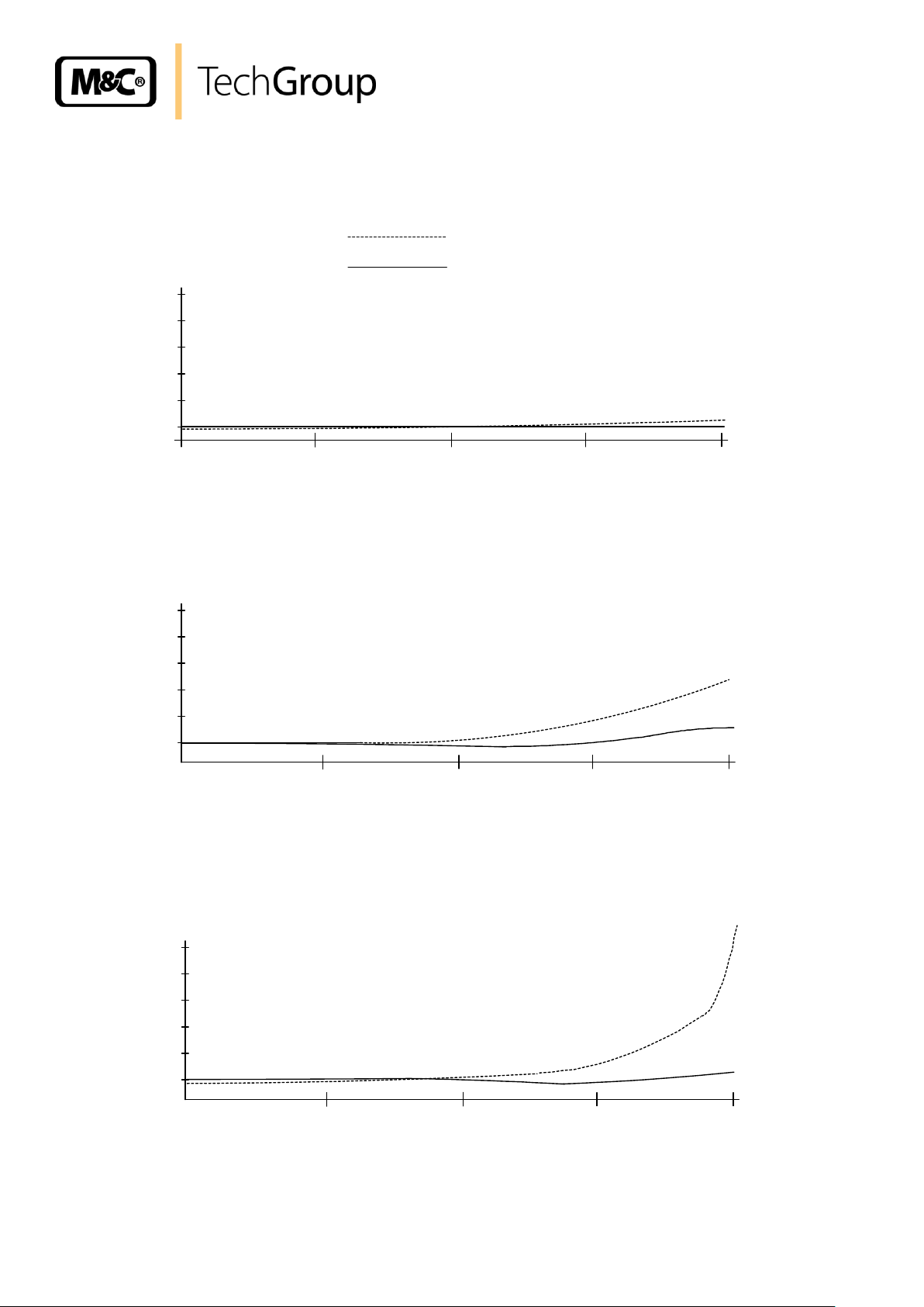
22 APPENDIX
Sample outlet dew point (ambient temperature 20°C) depending on heat exchanger material,
inlet dew point and gas flow rate
Circuit diagram EC automatic control board, drawing number : 2300 - 5.04.2
Circuit diagram EC30 (from 9/98), drawing number: 2389 - 5.01.3
Circuit diagram EC-30-control electronic, drawing number: 2389 - 5.02.3
Wiring plan automatic condensate removal unit EC-FD, drawing number : 2300-5.05.0
Further product documentation can be seen and downloaded from our home page:
www.mc-techgroup.com
Instruction manual peristaltic pump SR 25.1, Document : 3-7.1-MD;
Condensate vessel TG, TK, Document : 3-6.3.1
GL-connectors, Document : 3-5.1.1
Universal unit EC-D and EC-FD, Document : 3-4.4
Automatic liquid drain AD-SS, Document : 3-6.2.3
Automatic liquid drain AD-P, Document : 3-6.2.1
Gas sampling and gas conditioning technology 3-4.20-ME
Page 36
36
Sample outlet dew point
EC-G
10
5
187,5
125
250
°C
N l/hr
Gas flow rate
Sample outlet dew point
EC-SS
10 5 °C
N l/hr
Gas flow rate
Sample outlet dew point
EC-PV
10 5 °C
N l/hr
Gas flow rate
62,5
187,5
125
250
62,5
187,5
125
250
62,5
60°C
40°C
Sample outlet dew point (ambient temperature 20°C) depending on gas flow rate
sample inlet dew point
Figure 16 Sample outlet dew point
Gas sampling and gas conditioning technology 3-4.20-ME
Page 37

37
Figure 17 Circuit diagram EC automatic control board
Gas sampling and gas conditioning technology 3-4.20-ME
Page 38

38
Figure 18 Circuit Diagram EC-30
Gas sampling and gas conditioning technology 3-4.20-ME
Page 39

39
Figure 19 Circuit diagram control electronic EC-30
Gas sampling and gas conditioning technology 3-4.20-ME
Page 40

40
Figure 20 Wiring plan automatic condensate removal unit EC-FD
Gas sampling and gas conditioning technology 3-4.20-ME
 Loading...