

Page 1
CSS-VC1
Embracing Challenge
Gas Conditioning Unit series CSS®
Version CSS-VC1 for max. 1 x 250Nl/h gas ow rate,
Version CSS-VC2 for max. 2 x 150Nl/h gas ow rate,
for 19”- or wall mounting or portable in transport case
Special Features
Compact high-performance construc-
tion with compressor cooler
Individually congurable, also beyond
the scope listed here
Completely pre-installed
Multi functional expandable control unit
TCU with warning and fault indicator in
plain text
One or two gas streams
19”- or wall mounting housing or port-
able in transport case
Low maintenance and self-monitoring
Outlet dew point adjustable from +2 °C
to +7 °C
Dew point stability ± 0,1°C
Operational in 10 minutes
Light weight
Optimum reliability
Operating hours counter
Resettable service interval
History memory
Application
The units CSS-VC.. provide a complete preinstalled compact high-performance sample
gas conditioning for continuous use. Due to
the multi functional expandable control unit
TCU and a big variety of additional options
the gas conditioning units excellently can be
adapted to the most diverse requirements of
gas analysis technique and therefore assume
tasks of complete anlayse systems.
Its compact construction only takes up little
space. The CSS-VC units are ready for use in
a few minutes. This makes time-consumingprocurement of individual components and
assembly superfluous. Also a portable version
in transport case is possible.
Description
All components of the gas conditioning unit
are mounted in a robust compact sheet steel
case for wall- or 19»-rack mounting. The ventilation grids in the sidewalls ensure that the
equipment is sufficiently ventilated.
Filter, flowmeter and peristaltic pump are
placed into the front panel and thus assure a
very easy maintenance. Due to a removable
lid and a foldable front plate also quick and
easy inspection and maintenance of all other
built-in components, especially easy change
of heat exchangers is possible.
The compressor gas cooler is equipped with
one or two heat exchangers of Duran glass,
stainless steel SS316Ti or PVDF.
Peristaltic pumps type SR25.2 are used for
contiuous condensate removal or also used
as dosing pump.
The current cooler temperature is displayed
at the front panel mounted multi functional
control unit TCU. Via keys the set temperature
of the cooler can be adjusted. In case of warnings or faults in plain text are displayed and
additionally via LED’s indicated ( cooler within
set temperature range - green LED, flow alarm
(option) - yellow LED, temperature +-3°C from
set point and liquid alarm (option) - red LED.
The fine filter downstream cooler (different
filter executions possible) ensures the necessary solid separation. The condition of the
filter element is visible from outside.
For protection of downstream analysers
against liquid breakthrough and for increase
of operating safety of the whole system
depending on the chosen type of filter a
suitable liquid alarm is possible or already
integrated in the filter.
A collective alarm message or on request
single alarm message inclusive mA outlet
for cooler temperature connected to output
terminals is available. Alarm message and
switching off the sample pump if present
happens via potential free contacts for collective alarm resp. single alarms (cooler temperature, flow, liquid in the system).
The downstream installed sample gas pump
N3/5/9 KPE is available with 3 pump capacities.
The flow meter FM40 with corresponding
measuring range installed in the sample gas
outlet can be equipped with a flow alarm
sensor FA-20mo and the adequate electronic.
Additionally for each sample outlet a second
sample outlet resp. bypass, also with flowmeter and flowalarm as option can be set up.
In case of aerosol problems a liquid particle
filter can be installed downstream the flowmeter in the sample gas outlet.
Via extension modules for control unit TCU
two more temperature controllers e.g. for
control of heated sample lines or gas sample
probes are available. Also external sample
gas pumps can be switched and gas sample
probes individually be purged back.
Technical specications and illustrations are without
obligation, subject to modications. 04.12/06.13
M&C TechGroup Germany GmbH • Rehhecke 79 • 40885 Ratingen • Germany
info@mc-techgroup.com • www.mc-techgroup.com • Fon +49 2102 935-0 • Fax +49 2102 935-111
14.1a
Page 2
1
2
5
3
6
4
8
7
1
2
5
6
4
8
7
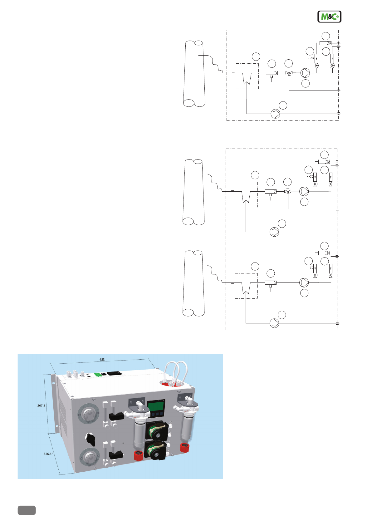
Example configuration CSS-VC1
1 Gas cooler series ECM-1
2 Option universal lter or front panel lter FPF-0,1GF, 0,1µm,
optional with liquid alarm LA or front panel lter
FPF+, optional with integrated liquid alarm
3 Option 3 or 5-way-ball valve 3L/PV or 5L/PV
4 Option sample gas pump N3/5/9KPE
5 Option peristaltic pump SR25.2
6 Option ow meter FM40 with ow alarm
7 Option ow meter FM40
8 Option liquid particle llter CLF-5/W or CLF-T(SS)
Example configuration CSS-VC2
1 Gas cooler series ECM-2
2 Option universal lter or front panel lter FPF-0,1GF, 0,1µm,
optional with liquid alarm LA or front panel lter
FPF-2-0,3GF, 0,3µm, with integrated liquid alarm
3 Option 3 or 5-way-ball valve 3L/PV or 5L/PV
4 Option sample gas pump N3/5/9KPE
5 Option peristaltic pump SR25.2
6 Option ow meter FM40 with ow alarm
7 Option ow meter FM40
8 Option liquid particle llter CLF-5/W or CLF-T(SS)
8
6
1
3
2
4
5
7
Dimensions CSS-VC..
Dimensions in mm
* 301,5 without wall mounting brackets
14.1a
M&C TechGroup Germany GmbH • Rehhecke 79 • 40885 Ratingen • Germany
info@mc-techgroup.com • www.mc-techgroup.com • Fon +49 2102 935-0 • Fax +49 2102 935-111
Technical specications and illustrations are without
obligation, subject to modications. 04.12/06.13
Page 3

Technical Data
Gas Conditioning Unit series CSS® Version CSS-VC1 Version CSS-VC2
Part No. 230V 50Hz 01G6050 01G6055
Part No. 115V/50-60Hz 01G6050a 01G6055a
Sample outlet dew point range of adjustment: +2 °C ..... +7 °C, factory setting: +5 °C
Dew point stability at constant conditions < ±0,1 °C
Sample inlet temperature **max. 180 °C
Sample inlet dew point **max.+80 °C
Gas flow rate **max. 250 Nl/hr **max. 2 x 150 Nl/hr
Ambient temperature **+5 °C up to +40 °C
Storage temperature -25 °C up to +65 °C
Pressure 0,7 bar up to 1,4 bar abs.
Total cooling capacity ** max. 144 kJ/hr
Number of gas inlets 1 2
Number of gas outlets 1 2
Condensate outlet 1 2
Medium connections tube connection 4/6 mm
Material of sample contacting parts Heat exchanger : glass, PVDF or stainless steel 1.4571
Tubing and fittings : PTFE, PVDF
Universal filter FP-2T-D : PVDF, FPM, glass, PTFE
Front panel filter FPF-0,1GF : PVDF, glass, FPM
Front panel filter FPF+ : PVDF, glass, FPM
Peristaltic pump SR25.2 : PVDF, Novoprene
Liquid particle filter CLF-5/W : PVDF, glass, FPM, PTFE
Sample gas pumps N3/5/9 : PVDF, PTFE, FPM
Flowmeter FM40 : PVDF, glass, FPM, Hastelloy C4
Ball valve 3L/PV and 5L/PV : PVDF, FPM
Ready for operation approx. 10 min.
Power supply 230V 50-60Hz ±10% resp. 115V 50-60Hz ±10%***
Power consumption max. 220VA + max. 300VA for the sample gas pumpfür die Messgaspumpen
Fuse protection 4A t, 5x 20 mm
Electrical connection Cold appliance plug with 2 m of cable
Case protection IP20 EN 60529
Housing protection sheet steel case for 19“- or wall mounting, lacquered RAL 7032
Equipment dimensions (H x W x D) 267,5 mm x 483 mm x 301,5 mm
(portable version : 355 mm x 515 mm x 395 mm)
Electrical equipment standard EN61010
Weight approx. 22 kg
PVDF = Polyvinylidenuoride
PVC = Polyvinylchloride
FPM = Fluor caoutchouc = Viton
PPH = Polypropylene hard
PTFE = Polytetraourethylene
** Technische Daten mit Max.-Angaben sind unter Berücksichtigung der Gesamtkühlleistung bei 25 °C und einem Ausgangstaupunkt von 5 °C zu bewerten.
*** 115V/50Hz sample gas pump as feature artticle possible
®
®
Options
Description Part No.
Heat exchangers and housing version
Extra charge for gas connections directly at one heat exchanger
Extra charge for heat exchanger ECM-1 out of glass for CSS-VC1, sample gas connections at the heat exchanger 93K0140
Extra charge for heat exchanger ECM-1 out of stainless steel SS316Ti for CSS-VC1, sample gas connections at the heat exchanger 93K0160
Extra charge for heat exchanger ECM-1 out of PVDF for CSS-VC1, sample gas connections at the heat exchanger 93K0170
Extra charge for gas connections directly at two heat exchangers 01G6063
Extra charge for heat exchanger ECM-2 out of glass for CSS-VC2, sample gas connections at the heat exchanger 97K0100
Extra charge for heat exchanger ECM-2 out of stainless steel SS316Ti for CSS-VC2, sample gas connections at the heat exchanger 97K0115
Extra charge for heat exchanger ECM-2 out of PVDF for CSS-VC2, sample gas connections at the heat exchanger 97K0110
Extra charge for gas connections of one heat exchanger in the joint plate for e.g. 19“ mounting 01G6060
Extra charge for heat exchanger ECM-1 90° out of glass for CSS-VC1, sample gas connections in the joint plate for e.g. 19“ mounting 93K0150
Extra charge for heat exchanger ECM-1 out of PVDF for CSS-VC1, sample gas connections in the joint plate for e.g. 19“ mounting 93K0170
Extra charge for gas connections of two heat exchangers in the joint plate for e.g. 19“ mounting 01G6061
Extra charge for heat exchanger ECM-2 90° out of glass for CSS-VC1, sample gas connections in the joint plate for e.g. 19“ mounting 97K0150
Extra charge for heat exchanger ECM-2 out of PVDF for CSS-VC1, sample gas connections in the joint plate for e.g. 19“ mounting 97K0110
Peristaltic pumps for condensate removal (max. 2 pcs.)
Extra charge for mounting a peristaltic pump SR25.2 for condensate removal, completely flexible tubed (one per gas path necessary) 01G6140
Filters (max. 2 pcs. front panel filters and 2 pcs. universal filters resp. aerosol filters) and liquid alarm
Extra charge for mounting of front panel filter FPF-0,1GF 04F1000
Technical specications and illustrations are without
obligation, subject to modications. 04.12/06.13
M&C TechGroup Germany GmbH • Rehhecke 79 • 40885 Ratingen • Germany
info@mc-techgroup.com • www.mc-techgroup.com • Fon +49 2102 935-0 • Fax +49 2102 935-111
01G6062
14.1a
Page 4

Options
Description Part No.
Extra charge for liquid alarm with flow chamber LS/LA2 at front panel filter FPF-0,1GF 03E3010
Extra charge for mounting a font panel filter FPF+ 04F2100
Extra charge for a filter element for FPF+ (depending on filter element) to choice
Extra charge for liquid alarm sensor LA3 integrated in FPF+ 03E1300
Extra charge for universal filter / aerosol filter CLF.. (depending on filter) to choice
Extra charge for mounting an universal filter / aerosol filter CLF on front plate (max. 2 pcs.) 01G6075
Extra charge for liquid alarm LA1S for universal filter F.-..-D 03E3001
Ball valves for test gas feeding (max. 1 pc.)
Extra charge for mounting a 3-way ball valve 3L/PV 01G9046
Extra charge for mounting a 5-way ball valve 5L/PV 01G9045
Sample gas pumps (max. 2 pcs.) (only with electronic controller 01G6175)
Extra charge for mounting sample gas pumps N..KPE 01G6070
Extra charge for mounting the sample gas pump N3KPE 01G6125
Extra charge for mounting the sample gas pump N5KPE 01G6130
Extra charge for mounting the sample gas pump N9KPE 01G6135
Flowmeter (max. 4 pcs. in total) and flow alarm (max. 2 pcs.)
Extra charge for mounting a flowmeter FM40 7-70Nl/hr in sample gas outlet 09F4000
Extra charge for mounting a fowmeter FM40 15-150Nl/hr in sample gas outlet 09F4005
Extra charge for mounting a fowmeter FM40 25-250Nl/hr in sample gas outlet 09F4010
Extra charge for mounting a fowmeter FM40 50-500Nl/hr in sample gas outlet 09F4015
Extra charge for flow alarm with forked light barrier FA-20mo 02E3500
Extra charge for second sample gas outlet resp. bypass with flow meter FM40 7-70Nl/hr 01G6200
Extra charge for second sample gas outlet resp. bypass with flow meter FM40 15-150Nl/hr 01G6210
Extra charge for second sample gas outlet resp. bypass with flow meter FM40 25-250Nl/hr 01G6220
Extra charge for second sample gas outlet resp. bypass with flow meter FM40 50-500Nl/hr 01G6230
Electronic controllers
Extra charge for electronic controller with collective status alarm 01G6170
Extra charge for single alarm messages (temperature, flow, liquid in the system) inclusive mA-outlet (4-20mA, or 0-20mA on request) for
cooler temperature for external temperature display
External additional modules (only with electronic controller 01G6175)
Extra charge for communication module (only necessary once for all extension modules of the TCU) 01B8620
Extra charge for temperature controller module (2 additional temperature controllers in TCU with 4 relays for excess resp. low temperature
monitoring) for control of solid state relays
For controller parameterization please specify with order which M&C devices should be controlled (type of gas sample probe(s) resp. type and length
of heated sample line(s)).
Extra charge for status module for collective alarm message via 1 changeover contact relay and 1 solid state relay for switching of external
sample gas pumps
Extra charge for blow back module for programmed control of solenoid valves for blow back of gas sample probes with status monitoring
(measuring/blow back), monitoring of the blow back pressure and control of the sample gas pumps (on/off)
Extra charge for M&C-bus for external modules 01G6180
Carrying case (only for 19“-version)
Extra charge for aluminium carrying case for portable gas conditioning 01G6250
Temperature controller for heated sample line (only with electronic controller 01G6175)
Extra charge for temperature controller for max. 10m heated sample line, 230V with PT100, with solid state relais and 7-pole plug 01G6190
Bending protection adapter for portable gas conditioning
Extra charge for bending protection for heated sample line DN4/6 01G9060
Extra charge for bending protection for heated sample line DN6/8 01G9061
01G6175
01B8640
01B8630
01B8650
Order example:
1x 01G6050 + 1 x 01G6060 + 1 x + 1x 93K0150 + 1 x 01G6140 + 1x 04F2100 + 1 x 90F0002 + 1 x 03E1300 + 1 x 03F3005 + 1 x 01G6075 + 1 x 01G6070 + 1 x
01G6130 + 1 x 09F4005 + 1 x 02E3500 + 1 x 01G6210 + 1 x 01G6175 + 1 x 01G9160 =
CSS-VC1, 230V, with heat exchanger out of glass, sample gas connections in the joint plate, built in peristaltic pump SR25.2, built in front panel filter FPF+2T
with integrated liquid alarm sensor LA3, aerosol filter CLF-5/W mounted on front panel, built-in sample gas pump N5KPE, flowmeter FM40 15-150Nl/hr and flow
alarm sensor FA-20mo in the sample outlet, flowmeter FM40 15-150Nl/hr in the bypass, single alarm messages and mA-outlet for external cooling temperature
indication, temperature controller module TCU.
14.1a
M&C TechGroup Germany GmbH • Rehhecke 79 • 40885 Ratingen • Germany
info@mc-techgroup.com • www.mc-techgroup.com • Fon +49 2102 935-0 • Fax +49 2102 935-111
Technical specications and illustrations are without
obligation, subject to modications. 04.12/06.13
Page 5

CSS-VC in aluminium carrying case
The CSS-VC can be delivered in a robust aluminium carrying case with 2 ergonomic handles, removable perspex front and termination technique easily accessible
from outside. Dimensions : 355 mm x 515 mm x 395 mm (H x W x D)
Application example
Technical specications and illustrations are without
obligation, subject to modications. 04.12/06.13
M&C TechGroup Germany GmbH • Rehhecke 79 • 40885 Ratingen • Germany
info@mc-techgroup.com • www.mc-techgroup.com • Fon +49 2102 935-0 • Fax +49 2102 935-111
14.1a
 Loading...