

Page 1
Manual
Gas conditioning series CSS
®
Version CSS VC1 and CSS VC2
for 19"- or wall mounting
or portable version in carrying case
with software version 1.6
Gas sampling and gas conditioning technology 14.1a ME
Page 2

Contents
1 General information ..................................................................................................................... 5
2 Declaration of conformity ............................................................................................................ 5
3 Safety ............................................................................................................................................ 6
4 Warranty ........................................................................................................................................ 6
5 Terminology and symbols used ................................................................................................. 7
6 Introduction .................................................................................................................................. 8
7 Application .................................................................................................................................... 9
8 Technical specifications ............................................................................................................ 10
8.1 Technical specifications for the expansion modules .............................................................. 11
8.2 Options ................................................................................................................................... 12
9 Description ................................................................................................................................. 15
10 Goods receiving and storage .................................................................................................... 16
11 Installation instructions ............................................................................................................. 17
11.1 Conversion to wall mounted or 19" rack housing ................................................................... 17
12 Supply connections ................................................................................................................... 18
12.1 Hose connections ................................................................................................................... 19
12.2 Lay the connectors on the rear panel ..................................................................................... 19
12.3 Connection of the heated line with antikink adapter for portable version (Art. No. 01G9060
or 01G9061) ........................................................................................................................... 20
12.4 Electrical connections ............................................................................................................. 20
12.4.1 Group connection alarm (Art. No. 01G6170) .................................................................... 21
12.4.2 Connection of individual alarms, external pump control and external cooler
temperature display (Art. No. 01G6175) ........................................................................... 22
12.4.3 Connection of heated line for portable version (Art. No. 01G6190) .................................. 23
12.4.4 Connecting the optional expansion modules .................................................................... 24
13 Commissioning .......................................................................................................................... 24
13.1 Cooler controller ..................................................................................................................... 25
14 Decommissioning ...................................................................................................................... 26
15 The multifunctional control unit TCU ....................................................................................... 26
15.1 Basic functions of the TCU ..................................................................................................... 26
15.2 Properties of the TCU ............................................................................................................. 26
15.3 Enhancements to the TCU ..................................................................................................... 27
15.3.1 The communication module .............................................................................................. 27
15.3.2 The temperature control module ....................................................................................... 28
15.3.3 The status module ............................................................................................................ 29
15.3.4 The backflush module ................................................................ ....................................... 30
16 Operation of the multifunctional control unit TCU ................................................................. 31
16.1 Display of control temperatures or cooling temperature curve ............................................... 32
16.2 Configure the switching on and off of the sample pumps ....................................................... 33
16.3 Configure backflushing ........................................................................................................... 34
16.4 Display of events .................................................................................................................... 35
16.5 Operating data ........................................................................................................................ 36
16.6 Resetting service and operating time ..................................................................................... 36
16.7 Setting service interval, language, control temperatures and temperature sensor types ....... 37
17 Alarms and faults ....................................................................................................................... 39
17.1 Meaning of the LEDs .............................................................................................................. 39
17.2 Temperature alarms from cooler and temperature control module ........................................ 40
17.3 Flow disturbance and liquid alarms ........................................................................................ 40
17.4 Other fault and alarm messages ............................................................................................ 41
18 Maintenance ............................................................................................................................... 41
18.1 Change the filter elements and O rings .................................................................................. 42
18.2 Maintenance of the sample gas pump(s) ............................................................................... 42
2 Gas sampling and gas conditioning technology 14.1a-ME
Page 3

18.2.1 Remove pump head Type N 3/5/9 KPE ............................................................................ 44
18.2.2 Replacing the diaphragm Type N 3/5/9 KPE ................................................................... 44
18.2.3 Valve plate change Type N 3/5/9 KPE ............................................................................. 44
18.2.4 Mount pump head type N 3/5/9 KPE ................................................................................ 44
18.2.5 CleaningType N 3/5/9 KPE ............................................................................................... 45
18.3 Maintenance of the built-in peristaltic pump type SR 25.2 ..................................................... 45
18.3.1 Exchange the pump hose ................................................................................................. 46
18.3.2 Change of contact pulleys and springs ............................................................................. 47
18.3.3 Cleaning the pump head ................................................................................................... 49
18.4 Cleaning of the cooling fins of the compressor cooler ............................................................ 49
19 Spare parts lists ......................................................................................................................... 50
20 Appendix .................................................................................................................................... 52
List of figures
Figure 1 Example of a gas flow diagram CSS-VC1 ................................................................... 9
Figure 2 Dimensions and possible construction CSS-VC.. ...................................................... 15
Figure 3 Connections in the connection panel of the CSS-VC.. ............................................... 18
Figure 4 Connection group alarm ............................................................................................. 18
Figure 5 Connecting heated line DN4/6 with antikink adapter ................................................. 20
Figure 6 Plug assignment for the version with group alarm (Art. No. 01G6170) ...................... 21
Figure 7 Upper and lower channel of CSS-VC2 ....................................................................... 21
Figure 8 Plug assignment for design with individual alarms (Art. No. 01G6175) ..................... 22
Figure 9 Connection examples for alarm outputs ..................................................................... 23
Figure 10 Heated line connection for portable version to 10A ................................................... 24
Figure 11 Electrical connections communication module .......................................................... 27
Figure 12 Electrical connections temperature control module ................................................... 28
Figure 13 Electrical connections status module ......................................................................... 29
Figure 14 Electrical connections backflush module ................................................................... 30
Figure 15 Front view of the TCU in normal operation without temperature control module ....... 31
Figure 16 Front view of the TCU in normal operation with temperature control module ............ 31
Figure 17 Maintenance of sample gas pump(s) ......................................................................... 43
Figure 18 Sectional drawing N3/5 KPE and N9 KPE ................................................................. 43
Figure 19 Components of the peristaltic pump SR25.2 .............................................................. 46
Figure 20 Replacing the pump hose .......................................................................................... 47
Figure 21 Disassembly of pump head and driver ....................................................................... 48
Figure 22 Check of axes and rolls .............................................................................................. 48
Figure 23 TCU menu .................................................................................................................. 56
14.1a ME Gas sampling and gas conditioning technology 3
Page 4

This manual does not purport to be complete and is subject to technical
changes.
© 09/2012 M&C TechGroup Germany GmbH. Reproduction of this
document or its content is not allowed without the express permission
of M&C.
CSS ® is a registered trademark.
4. Circulation: 06/2013
Dear Customer,
We have organised this manual to enable you to find and understand all the necessary information
about the product quickly and easily.
If nevertheless you should still have questions regarding the product or its use, do not hesitate to
contact us directly at M&C, or your local dealer. Contact addresses can be found in the appendix of
this manual.
Please also consult our homepage www.mc-techgroup.com for further information about our products.
There you will find the manuals and product data sheets for all M&C products and other information
in German, English and French for download.
4 Gas sampling and gas conditioning technology 14.1a-ME
Page 5

Headquarters
M&C TechGroup Germany GmbH Rehhecke 79 40885 Ratingen Germany
Tel: 02102 / 935 - 0
Fax: 02102 / 935 - 111
e-mail: info@mc-techgroup.com
www.mc-techgroup.com
1 GENERAL INFORMATION
The product described in this manual has been supplied in a safe and tested condition. For safe
operation and to maintain this condition, the information and instructions in this manual must be
followed. In addition, the appropriate transportation, proper storage and installation as well as careful
operation and maintenance are necessary.
For the proper use of this product, all information required for technical personnel is contained in this
manual.
2 DECLARATION OF CONFORMITY
CE Mark
The product described in this operating manual complies with the following EC Directives.
EMC Directive
The requirements of EC Directive 2004/108/EC "Electromagnetic compatibility" are met.
Low Voltage Directive
The requirements of EC - Directive 2006/95/EC "Low Voltage Directive" are met.
Compliance with this EC Directive has been verified according to DIN EN 61010.
Declaration of conformity
The EU declaration of conformity is available for download on the M&C homepage or can be
requested directly from M&C.
14.1a ME Gas sampling and gas conditioning technology 5
Page 6

3 SAFETY
Please note the following basic safety precautions when installing, commissioning and
operating the device:
Before operation and use of the equipment, read the operating manual. The instructions and warnings
listed in the operating manual must be followed.
Work on electrical equipment must only be performed by qualified personnel in accordance with the
regulations currently in force.
The requirements of VDE 0100 together with its associated standards and regulations must be
complied with for the creation of power installations with nominal voltages up to 1000V.
When connecting the device, ensure the correct mains voltage in accordance with the specifications
on the rating plate.
Protection against contact with dangerously high electrical voltages:
Before opening the equipment, it must be switched off. This also applies to any connected external
control circuits.
Only use the device in approved temperature and pressure ranges.
Ensure installation is weather-protected. Do not directly expose to dust, rain or liquids.
The device must not be operated in hazardous areas;
Installation, maintenance, monitoring and any repairs must be performed by authorised personnel in
compliance with the relevant provisions.
4 WARRANTY
If the device fails, please contact M&C directly, or your M&C authorised dealer.
Provided that the device is used correctly, we undertake to provide a 1 year warranty from the date of
delivery according to our terms of sale. Consumables are not covered by the warranty. The warranty
covers free repair at the factory or free replacement of the device sent free to the point of use. Returns
must be made in sufficient and proper protective packaging.
6 Gas sampling and gas conditioning technology 14.1a-ME
Page 7
DANGER!
means that death, serious personal injury and/or substantial property
damage will result if proper precautions are not taken.
WARNING!
indicates that death, serious personal injury and/or substantial
property damage might occur if proper precautions are not taken.
CAUTION!
means that minor personal injury may result if proper precautions
are not taken.
CA UTION!
without a warning triangle symbol, indicates that property damage
may result if proper measures are not taken.
AT TENTI ON
indicates that an undesirable result or an undesirable situation may
occur if the corresponding instructions are not followed.
NOTICE!
This is important information about the product or the appropriate
part of the manual to which particular attention should be paid.
SPECIALIST
PERSONNEL
These are persons who are familiar with the installation, use,
maintenance, and operation of the product and have the necessary
skills through training or instruction.
5 TERMINOLOGY AND SYMBOLS USED
14.1a ME Gas sampling and gas conditioning technology 7
Page 8

6 INTRODUCTION
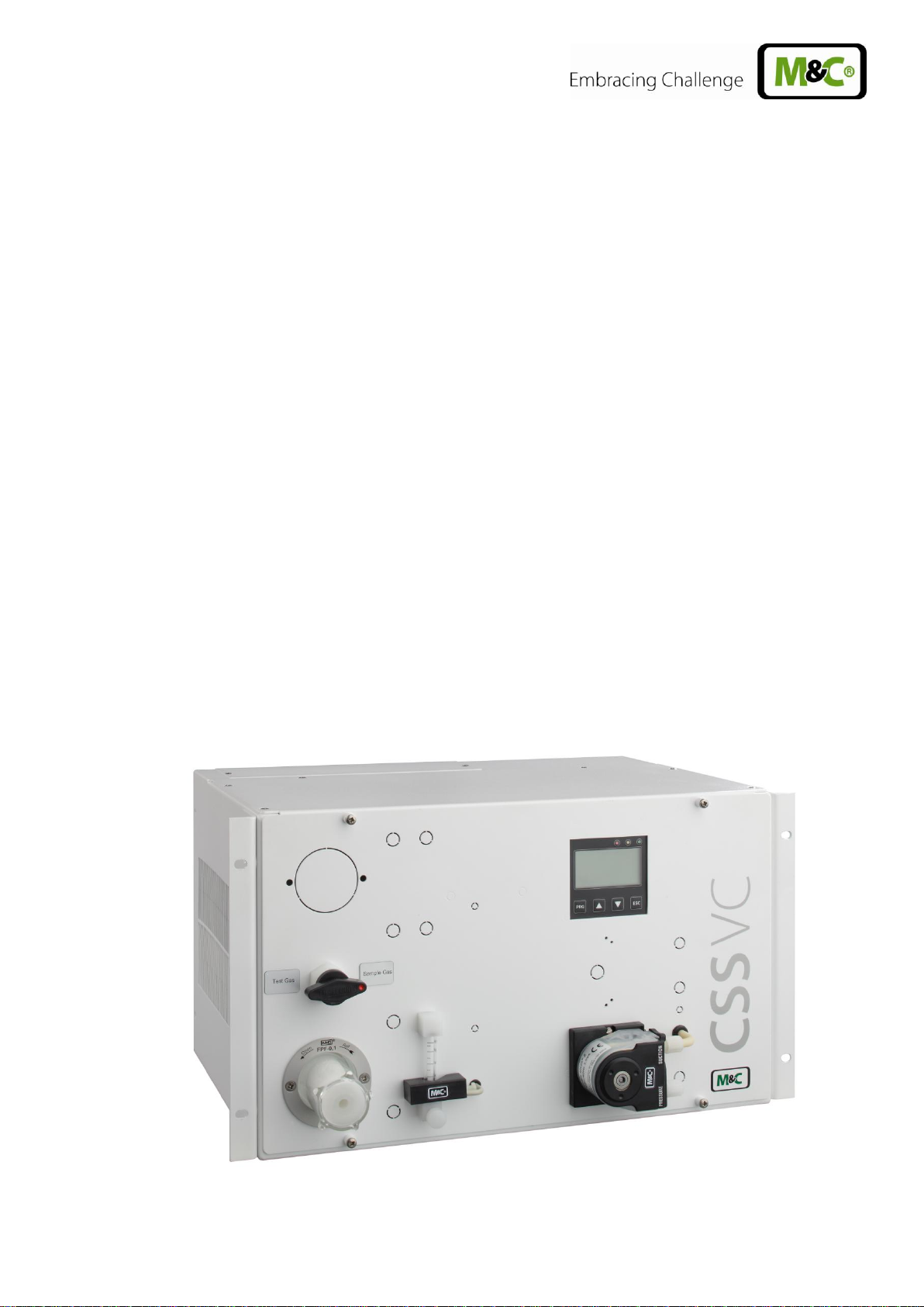
The gas conditioning CSS-VC unit, either for 19 "- or wall mounting or as a portable unit in carrying
case, is a fully pre-assembled compact continuously-operating gas purification system, which,
depending on the design, can supply a sample gas volume of max. 1 x 250Nl/h (CSS VC1) or 2 x
150Nl/h (CSS-VC2). Sample gas conditioning units are suitable due to their equipment and additional
options for the wide-ranging requirements of continuous gas analysis.
The entire gas conditioning unit is housed in a compact, rugged steel housing so that gas analyses
can be performed rapidly without a great deal of effort, with low maintenance and reliability.
Gas conditioning unit CSS-VC must not be used to support gas/air or gas/oxygen mixtures that are
ignitable during operation, for the supply of combustible gases that can form an ignitable mixture in
combination with air or oxygen, or in potentially explosive atmospheres and in potentially explosive
locations.
8 Gas sampling and gas conditioning technology 14.1a-ME
Page 9
7 APPLICATION
With the CSS-VC, fully pre-installed gas conditioning systems are created for continuous use, which
can be integrated perfectly into analytical systems. The compact design makes few demands on
space. The gas conditioning systems are operational within minutes. This renders time-consuming and
expensive procurement of individual components and small parts and their assembly unnecessary. A
portable version is also available in a carrying case.
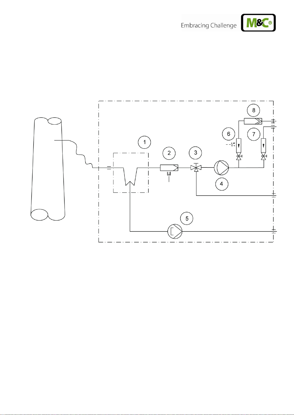
Figure 1 Example of a gas flow diagram CSS-VC1
Gas cooler series ECM-1
Option universal filter or front-installed filter FPF-0, 1GF, 0. 1μm, with optional liquid alarm LA
or front-installed filter FPF-2-0, 3GF, 0. 3μm, with integrated humidity alarm
Option 3 or 5-way ball valve 3L/PV or 5L/PV
Option sample gas pump N3/5/9KPE
Option peristaltic pump SR25.2
Option flow meter FM40 with flow alarm
Option flow meter FM40
Option liquid particulate filter CLF-5/W or CLF-T (SS)
In version CSS-VC2 there are 2 parallel gas lines in one gas conditioning unit.
14.1a ME Gas sampling and gas conditioning technology 9
Page 10
Gas conditioning series CSS ®
Version CSS-VC1
Version CSS-VC1
Article number 230V 50Hz
01G6050
01G6055
Article number 115V/50-60Hz
01G6050a
01G6055a
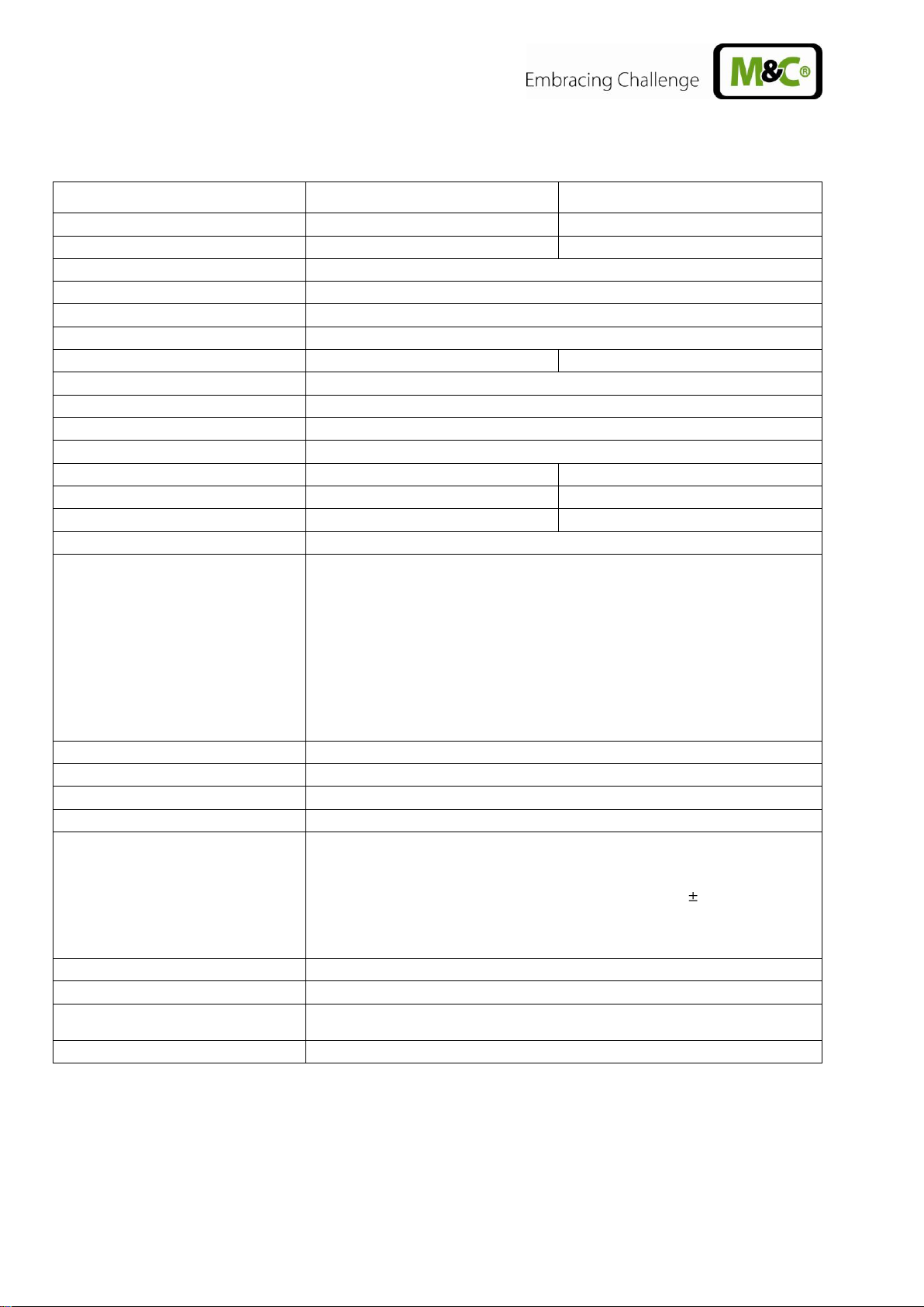
Gas outlet dew point
Setting range: + 2 ° C ..... + 7 ° C, factory setting: + 5 ° C
Dew point stability
under constant conditions < ± 0.1 ° C
Gas inlet temperature
**max. 180° C.
Gas inlet water-vapour saturation
**max. + 80 ° C
Gas flow
**max. 250 Nl/hr
**max. 2 x 150 l/h
Ambient temperature
** 10 ° C to + 40° C
Storage temperature
-25 ° C to + 65 ° C.
Pressure
0.7 bar to 1.4 bar abs.
Total cooling capacity **
max. 144 kJ/h
Number of gas inlets
1 2 Number of gas outlets
1 2 Condensate connection
1
2
Medium connections
Hose connection 4/6 mm
Material of parts in contact with
medium
Heat exchangers: Glass, PVDF or stainless steel 1.4571
Hoses/screwed connectors: PTFE/PVDF
Universal filter e.g. FP-2T-D: PVDF, FPM, glass, PTFE
Front-installed filter FPF-0.1GF: PVDF, glass, FPM
Front-installed filter FPF-2-0.3GF: PVC, FPM, PPH
Peristaltic pump SR25.2: PVDF, Novoprene ®
Liquid particle e.g. CLF-5/W: PVDF, glass, FPM, PTFE
Sample gas pumps N3/5/9: PVDF, PTFE, FPM
Flow meter FM40: PVDF, glass, FPM, Hastelloy C4
Ball valve 3L/PV and 5L/PV: PVDF, FPM
Operational
approx. 10 minutes.
Mains connection
230V 50-60Hz ± 10% or 115V 50-60Hz ± 10% ***
Power input
max. 220VA + max. 300VA for sample gas pumps
Device fuse
4A inert, 5x20 mm
Electrical connection
- Cold-device connector with 2 m cable
- Single alarm connections (11 & 12-pole) or status alarm(s)
(6-pole) : maximum capacity of the relays 24V 500mA
- mA-outlet : maximum load 500Ohm, accuracy 2% of
measuring range end value for display indication
- M&C Bus
- Heated sample line : maximum length 10m
Device protection class
IP20 to EN 60529
Housing design
Steel housing for 19"- or wall mounting, painted RAL 7035
Device dimensions (H x W x D)
267.5 mm x 483 mm x 301.5 mm
(Portable version: 355 mm x 515 mm x 395 mm)
Electrical device standard
EN 61010
8 TECHNICAL SPECIFICATIONS
FPM = Viton ®
PVDF = Polyvinylidene fluoride
PVC = Polyvinyl chloride
FPM = Fluorinated rubber
PPH = Hard polypropylene
PTFE = Polytetrafluoroethylene
**Technical specifications with maximum values must be rated in consideration of total cooling capacity at 25° C and an outlet dew point of 5 ° C.
*** 115V/50Hz sample gas pump available as a special item
10 Gas sampling and gas conditioning technology 14.1a-ME
Page 11
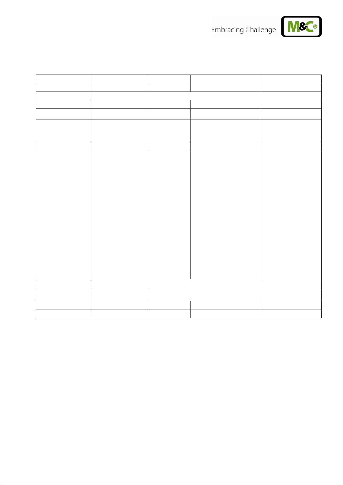
Module
Communication module
Status module
Temperature control module
Backflush module
Article No.
91 B 8620
91 B 8630
91 B 8640
91 B 8650
Power supply
24V DC + - 20%
internal
Earthing
L <3m
-
L <3m
Communication
M & C system (RJ-45) L
<3m
- - -
Inputs
2 x PT100 (2-wire)
L <30 m or
2 x thermocouples
L <30 m
-
-
Switching input
(Pressure switch)
Connection cable
length
see above
-
-
Max. 100 m
Outputs
-
Function: Status
1 potential-free
contact
(Changeover
switch 230VAC
1A)
(Can be used up
to 24V, 500mA!)
1 solid-state
output
230VAC 3A
Function: Pump1
1 solid state
output
230VAC 3A
Function: Pump 2
1 solid-state
output
230VAC 3A
2 x small signal digital output for
solid state relay control
24V max. 20mA
Function: High temperature
alarm
2 potential-free contacts
(N/O contact 230VAC 1A)
(can be used up to 24V
500mA!)
Function: Low temperature
alarm
2 potential-free contacts
(N/O contact 230VAC 1A)
(can be used up to 24V
500mA!)
Function: Measurement
1 potential-free contact
(Changeover switch
48VAC 1A)
(can be used up to 24V
500mA!)
Function: Backflush 1
1 solid-state output
230VAC 3A
Function: Control air
1 solid-state output
230VAC 3A
Function: Backflush 2
1 solid state output
230VAC 3A
Connection cable
length
-
Max. 100 m
Ambient temperature
max.
+ 60 ° C
Dimensions:
72 x 88 x 20mm
72 x 68 x 30mm
72 x 68 x 18mm
72 x 79 x 30mm
Weight
90 g
100 g
48 g
106 g
8.1 TECHNICAL SPECIFICATIONS FOR THE EXPANSION MODULES
The power consumption of all modules together is max. 140mA at 24V => 3.36 W.
14.1a ME Gas sampling and gas conditioning technology 11
Page 12
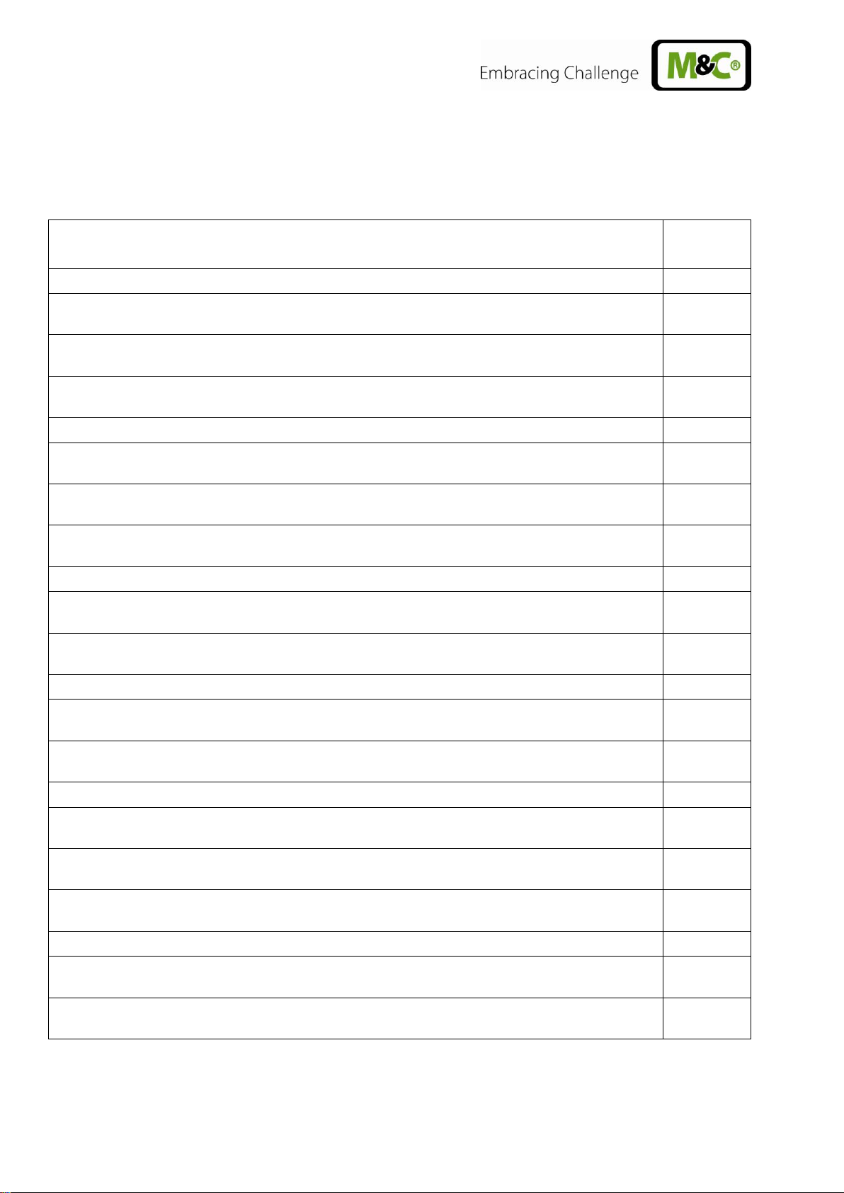
Description
Article No.
Extra charge for gas connections directly to a heat exchanger
01G6062
Extra charge for glass heat exchanger ECM-1 for
CSS-VC
1, sample gas connections on the
heat exchanger
93K0140
Extra charge for stainless steel heat exchanger ECM-1 for
CSS-VC
1, sample gas connections
on the heat exchanger
93K0160
Extra charge for PVDF heat exchanger ECM-1 for
CSS-VC
1, gas connections on the heat
exchanger
93K0170
Extra charge for gas connections directly to two heat exchangers
01G6063
Extra charge for glass heat exchanger ECM-2 for
CSS-VC
2, sample gas connections on the
heat exchangers
97K0100
Extra charge for stainless steel heat exchanger ECM-2 for
CSS-VC
2, sample gas connections
on the heat exchangers
97K0115
Extra charge for PVDF heat exchanger ECM-2 for
CSS-VC
1, sample gas connections on the
heat exchangers
97K0110
Extra charge for gas connections of a heat exchanger in the connection plate for e.g. 19" mount
01G6060
Extra charge for glass heat exchanger ECM-1 90 ° for
CSS-VC
1, sample gas connections in the
connection plate for e.g. 19" mount
93K0150
Extra charge for PVDF heat exchanger ECM-1 90° for
CSS-VC
1 sample gas connections in the
connection plate for e.g. 19" mount
93K0170
Extra charge for gas connections of 2 heat exchangers in the connection plate for e.g. 19" mount
01G6061
Extra charge for glass heat exchanger ECM-2 90° for
CSS-VC
2 sample gas connections in the
connection plate for e.g. 19" mount
97K0150
Extra charge for PVDF heat exchanger ECM-2 90° for
CSS-VC
2 sample gas connections in the
connection plate for e.g. 19" mount
97K0110
Extra charge for gas connections directly to a heat exchanger
01G6062
Extra charge for glass heat exchanger ECM-1 for
CSS-VC
1, sample gas connections on the
heat exchanger
93K0140
Extra charge for stainless steel heat exchanger ECM-1 for
CSS-VC
1, sample gas connections
on the heat exchanger
93K0160
Extra charge for PVDF heat exchanger ECM-1 for
CSS-VC
1, gas connections on the heat
exchanger
93K0170
Extra charge for gas connections directly to two heat exchangers
01G6063
Extra charge for glass heat exchanger ECM-2 for
CSS-VC
2, sample gas connections on the
heat exchangers
97K0100
Extra charge for glass heat exchanger ECM-2 for
CSS-VC
2, sample gas connections on the
heat exchangers
97K0100
8.2 OPTIONS
Beyond the standard scope of options of this for the CSS-VC, other customised options are possible
that cannot be listed in this manual.
12 Gas sampling and gas conditioning technology 14.1a-ME
Page 13
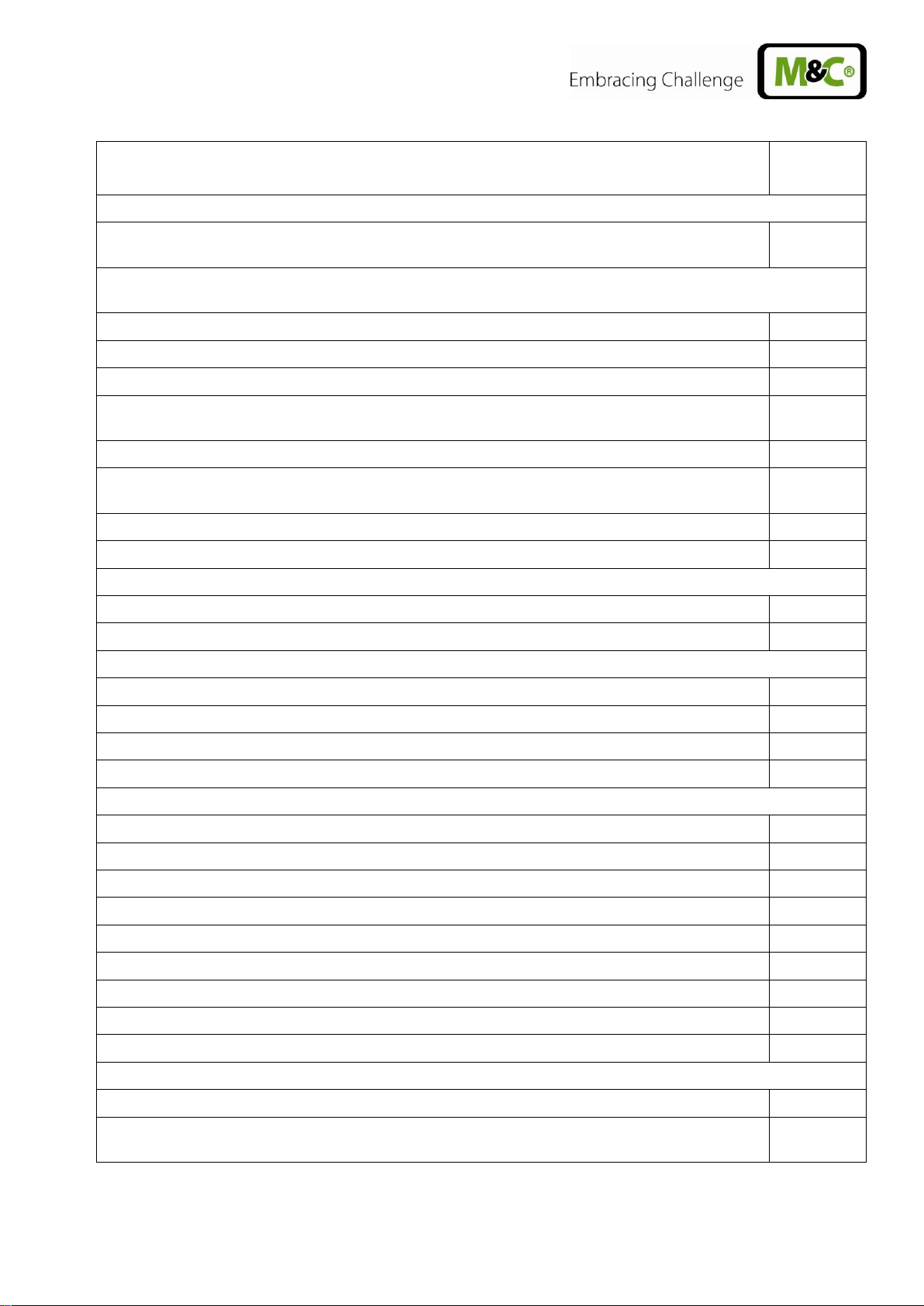
Description
Article No.
Peristaltic pumps for condensate disposal (max. 2 pcs.)
Extra charge for mounting a peristaltic pump SR25.2 for condensate disposal, with hoses preinstalled (one required for each gas line)
01G6140
Filter (max. 2 pcs. Front-installed filters and 2 pcs. Universal or aerosol filters) and liquid alarm (max. 2
pcs.)
Extra charge for installation of a sample gas filter FPF-0, 1GF
04F1000
Extra charge for liquid alarm with flow chamber LS/LA2 with sample gas filter FPF-0, 1GF
03E3010
Extra charge for installation of a sample gas filter FPF+
04F2100
Extra charge for filter element for FPF+ (see datasheet 7.2a)
according
to choice
Extra charge for liquid sensor LA3 integrated into FPF+
03E1300
Extra charge for universal filter (see data sheet 7.1)/aerosol filter CLF... (see data sheet 7.7 and
7.8)
according
to choice
Extra charge for installation of universal filter/aerosol filter CLF on front plate (max 2 pcs.)
01G6075
Extra charge for liquid alarm LA1S with universal filter F. -..-D
03E1001
Ball valves for calibration gas feeding (max. 1 pc.)
Extra charge for installation of a 3-way ball valve 3L/PV
01G9045
Extra charge for installation of a 5-way ball valve 5L/PV
01G9046
Sample gas pumps (max. 2 pcs., only with evaluation electronic system 01G6175)
Extra charge for installing sample pumps N.. KPE
01G6070
Extra charge for sample gas pump N3KPE
01G6125
Extra charge for gas pump N5KPE
01G6130
Extra charge for gas pump N9KPE
01G6135
Flow meter (max. 4 pc. total) and flow alarm (max. 2 pcs.)
Extra charge for installation of a flow meter FM40 7-70N1/h/in the sample gas outlet
09F4000
Extra charge for installation of a flow meter FM40 15-150Nl h/in the sample gas outlet
09F4005
Extra charge for installation of a flow meter FM40 25-250Nl h/in the sample gas outlet
09F4010
Extra charge for installation of a flow meter FM40 50-500Nl/h in the sample gas outlet
09F4015
Extra charge for flow alarm with forked light barrier FA-20mo
02E3500
Extra charge for second sample gas output or bypass flow meter FM40 7-70Nl/h
01G6200
Extra charge for second sample gas output or bypass flow meter FM40 15-150Nl/h
01G6210
Extra charge for second sample gas output or bypass with flow meter FM40 25-250Nl/h
01G6220
Extra charge for second sample gas output or bypass flow meter FM40 50-500Nl/h
01G6230
Electronic evaluation system
Extra charge for electronic evaluation system with group status alarm
01G6170
Extra charge for electronic evaluation system with individual alarm (temperature, flow, liquid in
system) including MA output for cooler temperature for external temperature display
01G6175
14.1a ME Gas sampling and gas conditioning technology 13
Page 14
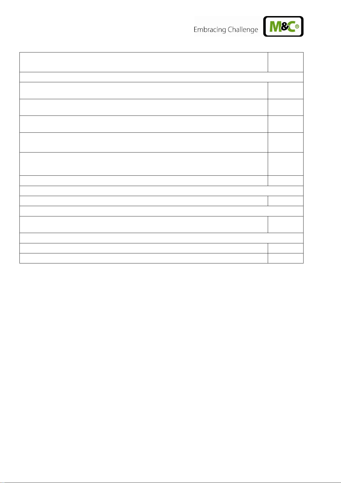
Description
Article No.
External expansion modules (only with electronic evaluation system 01G6175)
Extra charge for communication module (one-time necessity for all expansion modules of the
TCU)
01B8620
Extra charge for temperature control module (2 additional thermostats in TCU with 4 relays for
high or low temperature monitoring) for controlling solid-state relays
01B8640
Extra charge for status module for group alarm via 1 changeover relay and 1 solid-state relay for
switching external sample gas pumps
01B8630
Description
Article No.
Extra charge for backflush module for programmed control of solenoid valves for backflushing of
gas probes with status monitoring (measuring/backflush), monitoring of backflush pressure and
control of the sample pumps (on/off)
01B8650
Extra charge for
M&C
bus for external modules
01G6180
Transport case (19" version only)
Extra charge for carrying case for portable gas conditioning
01G6250
Temperature controller for portable version (only with electronic evaluation system 01G6175)
Extra charge for thermostat for maximum 10m heated line, 230V with PT100, with solid-state
relays and 7-pin connector
01G6190
Kink protection for portable gas conditioning
Extra charge for kink protection for heated line DN4/6
01G9060
Extra charge for kink protection for heated line DN6/8
01G9061
14 Gas sampling and gas conditioning technology 14.1a-ME
Page 15
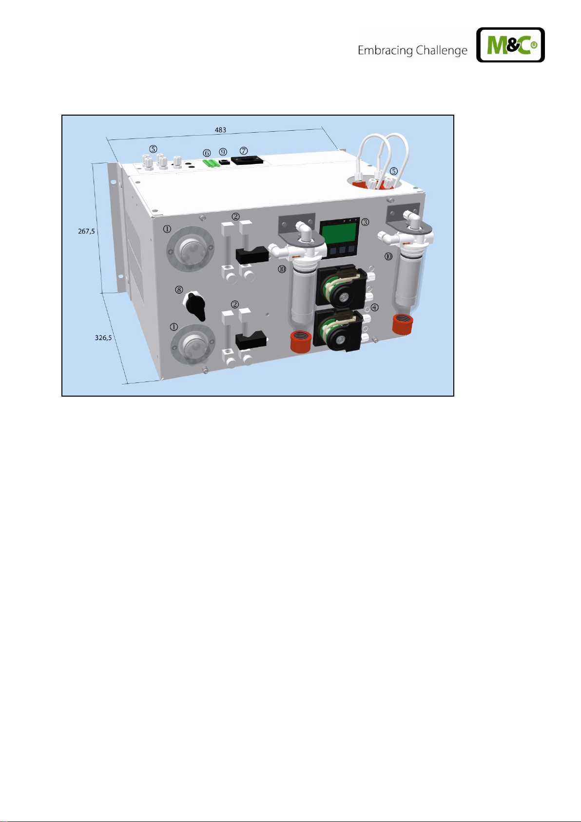
9 DESCRIPTION
Figure 2 Dimensions and possible construction CSS-VC..
Fine filter FPF-0, 1GF
Flow meter FM40 with and without forked light barrier FA-20mo
Multifunctional expandable controller unit TCU
Peristaltic pumps SR25.2 with condensate output at the pump
Sample gas inputs and outputs DN4/6 in connection plate or sample gas inputs on the heat
exchanger
Connection of group alarms (temperature, flow, liquid penetration)
Cold-device socket
3 or 5-way ball valve for calibration gas feeding or 3L/PV or 5L/PV
M&C bus interface
Aerosol filter CLF..
All components of the gas conditioning systems are installed in a strong compact steel housing for wall
or 19" mount. The ventilation grilles in the side walls provide adequate forced ventilation.
Filter, flow meter and peristaltic pumps are located in the front panel and thus ensure very simple
maintenance. Due to a removable lid and a hinged front panel, quick and easy inspection and
maintenance of all other built-in components is possible, in particular the easy changing of heat
exchangers.
The compressor gas cooler can be equipped with one or two heat exchangers made of glass, stainless steel or PVDF.
Peristaltic pumps of type SR25.2 are used for continuous condensate removal or as a metering pump.
14.1a ME Gas sampling and gas conditioning technology 15
Page 16

NOTICE!
Storage of the gas conditioning unit should be in a sheltered frost-free
room!
The current cooler temperature is displayed on the multi-functional control unit TCU mounted on the
front panel. The setpoint temperature of the cooler can be set by pressing keys. In the event of
warnings or faults, plain text information appears on the display and is also indicated by LEDs (e.g.
cooler within the setpoint range and no other alarms - green LED, flow alarm (option) - yellow LED,
temperature ± 3° C from the setpoint and humidity alarm (option) - red LED).
The fine filter downstream of the cooler (different filter types available) provides for the necessary
separation of solids. The condition of the filter can be judged from the outside. To protect the
downstream analysers against liquid penetration and to increase the operating reliability of the whole
system, according to the selected filter type, a suitable liquid alarm is possible or already integrated
into the filter.
A group alarm or on request individual alarms including mA output for the cooler temperature at the
output terminals is available wired. Via potential-free contacts for the group alarm or the individual
alarms (cooler temperature, flow, fluid in the system), an alarm message and shutdown of the sample
gas pump, if present, occurs.
Integrated sample gas pumps are available in three performance levels to choose from N3/5/9 KPE.
The flow meter FM40 arranged in the sample gas outlet with a measuring range adapted to the pump
power can be supplied for flow monitoring with a flow sensor FA-20mo. In addition, each sample gas
line can be equipped with a second sample gas outlet or bypass flow meter and flow control.
In the event of an aerosol problem, a liquid particulate filter CLF can be added downstream of the flow
meter in the sample gas outlet.
Via expansion modules for the control unit TCU two further temperature controllers are available e.g.
to regulate heated lines or gas probes. Here too external sample gas pumps can be connected and
individual sample gas probes can be backflushed.
10 GOODS RECEIVING AND STORAGE
The gas conditioning unit CSS-VC.. is a fully pre-assembled unit. In addition there are included:
1 x connection cable
1 x 6-pin or 11 and 12-pin connector
Optional 2 - 4 expansion modules
Immediately after arrival carefully remove the CSS-VC.. and any special accessories from the
dispatch packaging and check the supplied items in accordance with the delivery note and the list;
Check the goods for shipping damage and, if necessary, inform your transport insurer immediately
of any damage.
16 Gas sampling and gas conditioning technology 14.1a-ME
Page 17

NOTICE!
So that the unit is safe and operates reliably, it should be mounted
horizontally and without vibration. Only then is proper separation and
drainage of the condensate in the heat exchanger of the cooler
ensured.
The mounting of the gas conditioning unit should take place away from
heat sources and be freely ventilated so that there can be no disruptive
accumulation of heat.
When installed outdoors, adequate protection against direct sunlight
and moisture needs to be ensured. In winter, the place of installation
must be frost-free; ensure correct protection for the device.
Temperature variations, strong air movement and aggressive
atmospheres at the place of installation are to be avoided.
To ensure safe operation of the gas conditioning unit and downstream
analysers and to avoid false alarms, the gas conditioning unit should
not be used outside the specified temperature range. It must also be
protected against the ingress and accumulation of dust.
Downstream analysers and lines must operate at temperatures
significantly above the specified gas outlet dew point of +5 ° C. This
will avoid subsequent condensation of the gas in the connecting lines
to the analysers.
Unheated gas sample lines must be laid on a slope to the cooler.
11 INSTALLATION INSTRUCTIONS
11.1 CONVERSION TO WALL MOUNTED OR 19" RACK HOUSING
Gas conditioning units CSS-VC.., if not in a carrying case, are delivered with wall-mounting or 19"
housing.
Depending on which housing is required, the gas conditioning unit can be converted very simply by
moving the mounting bracket:
Remove two screws per bracket
Align bracket to the mounting holes according to the desired housing forward or rearward
Secure the bracket flush with the housing panel (19" mounting) or with protrusion to the rear
(wall mounting) with the two fixing screws on the housing
14.1a ME Gas sampling and gas conditioning technology 17
Page 18

12 SUPPLY CONNECTIONS
Figure 3 Connections in the connection panel of the CSS-VC..
Depending on the version of the CSS-VC, instead of the 11 and 12-pin connector for single alarms,
mA output cooler temperature and external sample gas pump control, a 6-pin connector may also be
present for group alarm (see Figure 4 ). The sample gas inlet, depending on the version, may also lie
directly on the heat exchangers.
Figure 4 Connection group alarm
In the portable version of the CSS-VC.., the supply connectors shown above are located on the rear
panel of the housing. The RJ45 connector is not present here. With the temperature controller option
for the portable version (Art. No. 01G6190), a 7-pin connector (see section 0) is present at the position
of the RJ45 connector in Figure 3.
18 Gas sampling and gas conditioning technology 14.1a-ME
Page 19

NOTICE!
Do not confuse the hose connections. They are marked appropriately.
After connecting all the lines, they should be checked to ensure there
are no leaks.
NOTICE!
The tightness of the connection can only be guaranteed if the
hose has a straight end edge (using a hose cutter).
WA RNING !
Possible aggressive condensate.
Wear protective glasses and proper protective clothing!
12.1 HOSE CONNECTIONS
The connection of the sample gas input, depending on the connection type, is directly on the heat
exchanger or on the clamping plate.
The condensate connections are made directly to the hose pump.
All hose connections are standard DN4/6mm ferrule hose fittings made of PVDF, for gas inlet
temperatures up to 105° C (see section 8 ).
Installation of the sample gas hoses or the condensate hose must be carried out as follows:
Loosen the clamping ring screwed fitting counterclockwise; It is important to ensure that the nut is
carefully removed from the threaded joint, so that the loose clamping ring which is in the nut is not
lost;
Slide the nut over the hose connection;
Slide the clamping ring with the thicker bulge facing the nut, onto the connection hose;
Attach the hose to the nipple in the threaded support;
Hand-tighten the nut.
The hose is now mounted slip-proof and pressure-tight.
The dismantling of the hoses is carried out in the reverse order.
12.2 LAY THE CONNECTORS ON THE REAR PANEL
If, for example with the 19" mounting, mounting conditions require the connections to be moved up in
the connection panel onto the back of the device, this is quite possible:
Remove the connection-panel mounting screws (see Figure 3)
14.1a ME Gas sampling and gas conditioning technology 19
Remove the cover-bracket mounting screws on the rear panel
Page 20

Sample gas IN
bulkhead fitting
Pressure ring 6mm Øi
Pressure ring 10mm Øi
Clip ring 10mm Øi
Clip ring 6mm Øi
Support sleeve 4mm
Junction nut 10mm Øi
Heated sample line
Adapter
WA RNING !
Incorrect voltage can destroy the device. On connection, ensure
the correct mains voltage in accordance with the rating plate!
NOTICE!
For the erection of power installations with nominal voltages up
to 1000V the requirements of VDE 0100 and relevant standards
and regulations must be complied with!
Mount the connection plate with 2 mounting screws on the rear panel
Mount the cover bracket with 2 connection screws on the device cover
12.3 CONNECTION OF THE HEATED LINE WITH ANTIKINK ADAPTER FOR
PORTABLE VERSION (ART. NO. 01G9060 OR 01G9061)
Figure 5 Connecting heated line DN4/6 with antikink adapter
Place special adapters according to the above drawing on Teflon tubing;
Slide the support sleeve slide into the Teflon tubing;
Draw the Teflon tubing all the way into the bulkhead union 'Sample Gas ON' and hand-tighten
the adapter;
Tighten the adapter with wrench (SW 14) 1 1/4 turns; here hold the lock nut of the bulkhead
union with a wrench (SW 15);
Insert the 10mm pipe of the heating line all the way into the adapter and hand-tighten using the
nut;
Tighten nut with wrench (SW 19), 1 1/4 turns; here hold the adapter with wrench;
The union is now cut to be gas-tight and can be loosened as often as required.
12.4 ELECTRICAL CONNECTIONS
20 Gas sampling and gas conditioning technology 14.1a-ME
Page 21

1
2
3
4
5 6 Internal
External
Status Alarm
Contact load
Contact rating
24V AC/DC 0,5A
Plug/male connector type Phoenix MSTB
2,5/6-STF 5,08
Socket/Female X2
Upper Channel
Channel 2
Lower channel
Channel 1
The CSS-VC.. is to be supplied in voltages 230V/50Hz or 115V/50-60Hz (for the circuit diagram see
Appendix). Protection is provided as standard with two 4A fuses. These are located in the cold-device
socket.
The electrical connection is via the 2m long power cord with cold-device connector depending on the
mounting of the connection plate either at the back or in the lid of the housing (see Section 12.2).
12.4.1 GROUP CONNECTION ALARM (ART. NO. 01G6170)
The electrical connection of the general alarm (condenser, fluid and flow) is via a 6-pin connector,
depending on the mounting of the connection plate, either at the back or in the lid of the housing.
The corresponding 6-pin socket is included.
The connector is wired as follows:
Figure 6 Plug assignment for the version with group alarm (Art. No. 01G6170)
Figure 7 Upper and lower channel of CSS-VC2
14.1a ME Gas sampling and gas conditioning technology 21
Page 22

NOTICE!
For the alarm relays „safety first“ is valid, i.e. contacts are open
currentless and in case of alarm.
For external pump control potential free contacts have to be used!
Switch open => pump off
Switch closed => pump on
12.4.2 CONNECTION OF INDIVIDUAL ALARMS, EXTERNAL PUMP CONTROL AND
EXTERNAL COOLER TEMPERATURE DISPLAY (ART. NO. 01G6175)
The electrical connection of the individual alarms is via two connectors, depending on the mounting of
the connection plate, either on the back or in the lid of the housing.
The corresponding 11 and 12-pin connectors are included.
The connectors are assigned as follows:
Figure 8 Plug assignment for design with individual alarms (Art. No. 01G6175)
On X2 connector pin 10-12, external switches can be connected for controlling the sample gas pumps
(internal or external).
On X2 connector pin 7+8, an indicator can be connected that warning messages are present (yellow
LED lights up on the front of the TCU).
On X2 connector pin 7+9, an indicator can be connected that alarm messages are present (red LED
lights up on the front of TCU).
On X2 connector pin 1+6, an indicator can be connected that a cooler temperature alarm is present
(excess or low temperature alarm).
On connector X2 pin 1+2, 1+3, 1+4, 1+5, an indicator can be connected that excess or low
temperature alarms of the optional temperature controller module are present.
22 Gas sampling and gas conditioning technology 14.1a-ME
Page 23

NOTICE!
Route the indicator lines separately from the power supply lines.
On connector X2.1 pin 3+8, 3+9, 3+10, 3+11 respectively, an indicator can be connected that flow
alarm messages are present. Since this is a warning message, the yellow LED on the front of the TCU
lights up.
On X2.1 connector pin 3+4, 3+5, 3+6, 3+7 respectively, an indicator can be connected that liquid
alarm messages are present. Since this is an alarm message, the red LED on the front of the TCU
lights up.
On connector X2.1 pin 1+2, an indicator of cooler temperature can be connected (standard 4-20mA.
0-20mA if ordered).
Figure 9 Connection examples for alarm outputs
14.1a ME Gas sampling and gas conditioning technology 23
Page 24

3 Mains
probe
1 Mains L
2 Mains N
4 Mains
probe
6 PT100
5 PT100
NOTICE!
The RJ45 socket is only suitable for the connection of the
communication module. A network connection is not possible with it!
WA RNUNG!
Before comissioning exclude that for one channel as well
internal as external a PT100 is connected.
12.4.3 CONNECTION OF HEATED LINE FOR PORTABLE VERSION (ART. NO. 01G6190)
If, for the portable version in a carrying case, the option temperature controller for heated line (Art. No.
01G6190) is selected, on the rear of the housing of the CSS-VC.. there is a 7-pin connector for
connection of heated lines type PSP and PSP 4M and PSP 4M-W. These have at the point of
connection and termination a 7-pin connector and a 7-pin socket for connection to the portable gas
conditioning unit CSS-VC.. and the portable gas sampling probe type PSP4000H. This is the power
supply to the heated line and gas sampling probe using the CSS-VC...
Figure 10 Heated line connection for portable version to 10A
12.4.4 CONNECTING THE OPTIONAL EXPANSION MODULES
The connection of expansion modules to the CSS-VC.. is via the communication module with the
appropriate cable to the RJ-45 socket in the connection panel (see Figure 3).
The electrical connection of the individual expansion modules is described in Section 15.
13 COMMISSIONING
Before commissioning, the plant and process-specific safety measures must to be observed.
Before switching on the power supply, it should be checked again that the operating voltage (see
nameplate) and the power supply voltage correspond!
24 Gas sampling and gas conditioning technology 14.1a-ME
Page 25

NOTICE!
In the case of long-term measurements with high dust content in
the sample gas, a suitable gas sampling probe to protect the
sample line from clogging must be provided.
Display
LED red
LED yellow
LED green
Status message
After
commissioning
> 8° C (room
temperature)
ON (status
alarm)
Lights up in the
case of an existing
flow alarm
OFF
Hightemp.: 1
Pump-warn.: 1.2 (when
pump is connected and
configured accordingly,
see Section 16.2)
After about. 10
min.
5.5 ° C
OFF
OFF
ON (cooling)
OK
Normal operation
5 ° C
OFF
OFF
ON (cooling)
OK
NOTICE!
If a cooler temperature alarm is present, after default setting, the
gas sample pumps are switched off (if available) to prevent the
transport of wet sample gas into the analyser.
The following steps are to be carried out before initial commissioning:
Plug the cold-device connector of the supplied mains connection cable into the cold-device socket
for gas conditioning;
Connect power cord to the network;
Switch on power supply.
After the end of the lead time, the gas conditioning unit is ready for operation (green LED on the
controller lights up).
13.1 COOLER CONTROLLER
14.1a ME Gas sampling and gas conditioning technology 25
Page 26

NOTICE!
The location of the compact conditioning unit must remain frost-
free, even during periods when the unit is switched off.
WA RNING !
Possible aggressive condensate.
Wear protective glasses and proper protective clothing!
14 DECOMMISSIONING
On short-term decommissioning of the gas conditioning unit CSS-VC.. no special measures need to
be taken.
For long-term decommissioning, it is recommended to flush the gas conditioning unit with ambient air
or inert gas. A flushing time of 3 to 5 minutes is sufficient under normal conditions. Likewise,
condensate residue must be removed from the system.
15 THE MULTIFUNCTIONAL CONTROL UNIT TCU
The multifunctional control unit TCU in the front panel of the gas conditioning unit CSS-VC.. can
undertake a series of different tasks centrally and provide wide-ranging system information.
15.1 BASIC FUNCTIONS OF THE TCU
1 x temperature controller for the integrated sample gas cooler
Evaluation of max. 2 liquid alarm sensors
Evaluation of max. 2 flow monitoring sensors
An mA output for external cooler temperature display e.g. in the control room
Control (on/off) of 2 sample gas pumps depending on the cooler temperatures and liquid alarms or
permanent switching on or off. In addition, setting of external pump control yes/no
Optional 1 x temperature controller for max. 10m heated hose for portable version (Art. No.
01G6190)
With expansion modules backflush programme for gas sampling probes, 2 more temperature
controllers for heated line(s) and/or gas sampling probe(s) and the control of external sample
pumps are possible
15.2 PROPERTIES OF THE TCU
Menu navigation with 3 language selections (German, English, French)
Error history (32 messages)
Detailed status indicators: Group alarm or individual alarm (cooler temperature, liquid flow),
warnings, OK condition, control temperature, temperature gradient, total running time after
service, error-free time
Configuration options: Service interval, language, pump control, temperature control and
backflush programme
26 Gas sampling and gas conditioning technology 14.1a-ME
Page 27

WA RNUNG!
Before comissioning exclude that for one channel as well
internal as external a PT100 is connected.
15.3 ENHANCEMENTS TO THE TCU
The TCU can be expanded by up to 4 modules in the range of functions. The modules are plugged
together according to requirements and provided for rail mounting.
15.3.1 THE COMMUNICATION MODULE
Communication of the TCU with the expansion modules is always with the communication module via
the M&C bus. This is therefore the base module for all other modules.
The TCU or CSS-VC.. and communication module are connected via RJ45 sockets.
On the communication module there are the temperature sensor ports (PT100 or thermocouples E, J,
T, K, N) of the temperature controller module.
Figure 11 Electrical connections communication module
14.1a ME Gas sampling and gas conditioning technology 27
Page 28
NOTICE!
If the CSS-VC.. is purchased with an external thermostat module, it
must be specified at the time of ordering which devices should be
regulated (2 probes or 2 heated lines or 1 probe and 1 heated line) so
that the controller can be configured accordingly.
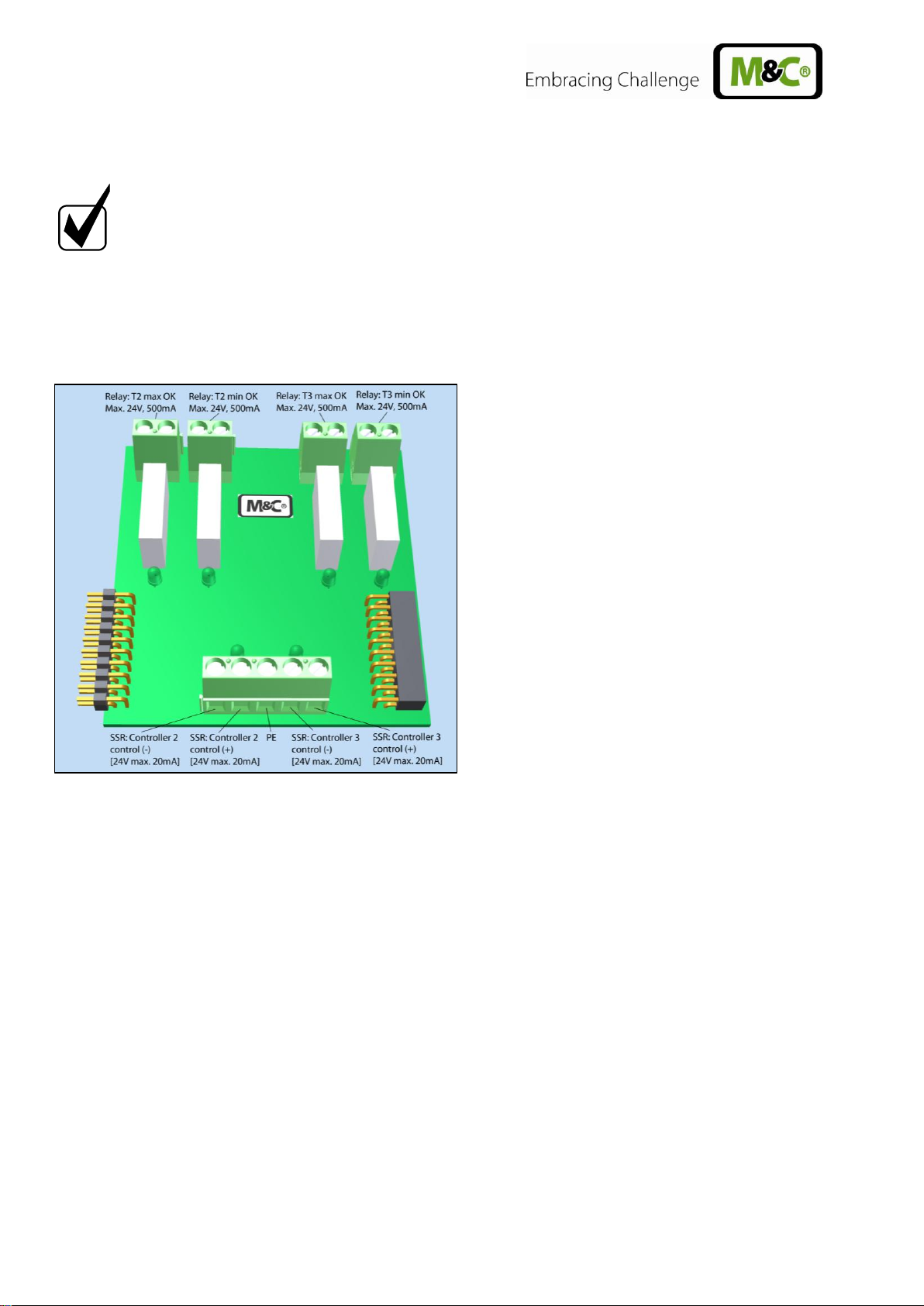
15.3.2 THE TEMPERATURE CONTROL MODULE
The temperature control module includes 2 additional thermostats e.g. for control of heated lines or
gas sampling probes. Control is by control of external solid-state relays. The module also includes 4
relays for high and low temperature monitoring. The connections for the temperature sensors are
located on the communication module.
Figure 12 Electrical connections temperature control module
28 Gas sampling and gas conditioning technology 14.1a-ME
Page 29

15.3.3 THE STATUS MODULE
On the status module, by the group alarm message of the TCU a changeover relay and a solid-state
relay are connected. These can be used for alarm indication. In addition, external sample gas pumps
can be switched off via two further solid-state relays e.g. in the event of an alarm and switched on
under good conditions. For external control of the pumps, see Section 12.4.2.
Figure 13 Electrical connections status module
14.1a ME Gas sampling and gas conditioning technology 29
Page 30

15.3.4 THE BACKFLUSH MODULE
With the backflush module, on the TCU a backflush programme can be set for gas sampling probes
(duration of a backflush pulse, number of backflush pulses, time between backflush pulses, timing of
backflush). The programme switches with time delay two solid-state relays with which in turn solenoid
valves can be switched, which accordingly release purging air to the gas sampling probe.
At start and end of a backflush programme, another solid-state relay is switched one second before
start and after the end of the programme, with which a solenoid valve can be controlled, which
releases control air to shut off and open the sample gas output of the gas sampling probe with
pneumatic valve.
In addition, at the start and end of a backflush programme, a changeover relay for status monitoring
(measuring/backflush) is switched. Here at the TCU dead time can be specified to ensure that, on the
"Measure" message, sample gas is currently flowing in the analyser. In addition, a connection is
present for pressure monitoring of the backflush gas. For this purpose, a pressure switch is connected
in the backflush line which closes the contact at upcoming pressure.
Figure 14 Electrical connections backflush module
30 Gas sampling and gas conditioning technology 14.1a-ME
Page 31

16 OPERATION OF THE MULTIFUNCTIONAL CONTROL UNIT TCU
In normal fault-free operation, the TCU display shows the current cooling temperature and the green
LED is lit constantly when the cooler temperature is within the alarm limits. The bottom line of the
display shows "status: OK" or current warning and error messages.
Figure 15 Front view of the TCU in normal operation without temperature control module
If the external temperature controller module has been purchased with the CSS-VC.., under error-free
normal operation, the temperature of the devices to be controlled (gas sampling probe (probe) and/or
heated sample gas line (B. line)) is indicated.
Figure 16 Front view of the TCU in normal operation with temperature control module
From any screen (except single temperature view and Service Reset) returns the TCU after 60s back
into the temperature overview without any key being pressed. If appropriate, altered and unapproved
settings jump back to the original state.
14.1a ME Gas sampling and gas conditioning technology 31
Page 32

16.1 DISPLAY OF CONTROL TEMPERATURES OR COOLING TEMPERATURE CURVE
By 1 x pressing of the arrow button, the following screen will appear on the CSS-VC.. without an
external temperature control module:
If the external temperature control module was purchased with the CSS-VC.., there is a choice as to
which display will appear here after the PRG key has been pressed once.
Selection is made with the arrow keys (flashing) and
confirmed by pressing the PRG key again .
The following displays are available to choose from, depending on the controller configuration:
Cooler temperature Probe temperature Temp. heated line Cooling temperature curve
32 Gas sampling and gas conditioning technology 14.1a-ME
Page 33

16.2 CONFIGURE THE SWITCHING ON AND OFF OF THE SAMPLE PUMPS
By 2 x pressing of the arrow key and then 1 x pressing of the PRG key, the following view
appears:
Here it is visible whether the pump is working or not. Using the arrow keys, the pump to be
configured can be selected. By pressing the PRG key again, the following view will appear:
Using the arrow keys, the parameters to be
changed can be selected. By pressing the PRG key,
the parameter can now be changed with the arrow keys
and then confirmed with the PRG key or
discarded with the ESC key .
Here you select the parameter to be taken into consideration for switching off the pump.
- = Not taken into consideration/= x is taken into consideration
T1 = Pump off with cooler temperature alarm (default setting x)
T2 + T3 = Pump off with temperature alarms from external temperature control module or
Temperature controller for heated line in portable version (Art. No.. 01G6190)
(Factory setting x)
Ext = external pump control (with closed switch on) (Default setting -)
LA = Pump 1 resp. 2 off with liquid alarm 1 resp. 2 (x factory setting) At activated reset
(see 16.7) R occurs behind – or x.
On = Pump is always on (overrides all other settings) (default setting -)
Off = Pump is always off (overrides all other settings) (default setting -)
RSp = Pump off during backflush programme (default setting x)
14.1a ME Gas sampling and gas conditioning technology 33
Page 34

16.3 CONFIGURE BACKFLUSHING
By 3 x pressing of the arrow key, then 1 x pressing of the PRG key, the following view
appears when the backflush module is connected:
Using the arrow keys, the parameters to be
changed can be selected. By pressing the PRG key,
the parameter can now be changed with the arrow keys
and then confirmed with the PRG key or
discarded with the ESC key .
Here the backflushing of gas sampling probes is determined:
Start in = specifies the time of the first backflushing.
Flushing time T1 = Duration of backflushing in a channel
Deadtime = Delay after the end of backflushing in channel 2 until the indication
shows "Measure" (changeover switch on the backflush module is switched)
Interval T2 = Period until the next backflush
On time T3 = Duration of a backflush pulse
Off time = Duration between backflush pulses
Pulse number i = Number of resulting backflush pulses (cannot be entered)
Activation = Backflush programme is to run (on) or not (off). When deactivating, "Start in" = 0
is set.
A programmed backflush runs always automatically after
a delay of T1 on two channels. Thus, for example 2 gas
sampling probes directly following one another or first the
internal probe (/ BB/F), and then the pre-filter (/ BB) are
backflushed. The dead time for channel 1 is therefore
always extended to T1.
If only one gas sampling probe is backflushed, T1 must
be added to the dead time or already represents sufficient
dead time, so that the value for the dead time can be set
to 0.
This menu appears only when the communication module is connected in conjunction with the
backflush module (automatic detection).
34 Gas sampling and gas conditioning technology 14.1a-ME
Page 35

Parameters:
Default setting
Info
Start in:
0d 0h 0m
Max.: 9T 23h 59m
Flushing time T1
30s
Max.: 99m 59s
Dead time
60s
0-120s
Interval T2
24h
On time T3
1s
Max.: 99s
Off time T4
5s
Max.: 99s
Pulse number
10
Is only calculated and cannot be <1
Activation
Off
16.4 DISPLAY OF EVENTS
By 4 x pressing (3 x without backflush module) of the arrow key and then 1 x pressing of the PRG
key, the event list appears in which the last 32 error messages and warnings are listed on 8
pages. The individual pages can be seen by using the arrow keys .
At the bottom of the list of events, furthermore, the error-free time and the total run time (operating
time counter) are displayed. The error-free time indicates how much time has passed since the last
error. The total running time indicates how long the device has been running since the last service.
If service reset is performed, the error messages are erased and the times reset.
During a power failure, the data remains stored.
14.1a ME Gas sampling and gas conditioning technology 35
Page 36

NOTICE!
A reset can only be carried out when no alarm is present!
16.5 OPERATING DATA
By 5 x pressing (4 x without backflush module) of the
arrow key (or 1 x pressing of the arrow key ) the
following view appears:
Here the actual device temperature, the period until the
next service warning, the service interval, the software
version and serial number are displayed.
By pressing the arrow key again, the display of the
control temperature reappears.
16.6 RESETTING SERVICE AND OPERATING TIME
Service and operating time can be reset as follows:
Press the ESC key and press both arrow keys at the same time. The following
screen appears:
Press the PRG key . Service life and operating time are reset and “Service OK” occurs.
With the ESC key resetting can be cancelled.
36 Gas sampling and gas conditioning technology 14.1a-ME
Page 37

16.7 SETTING SERVICE INTERVAL, LANGUAGE, CONTROL TEMPERATURES AND
TEMPERATURE SENSOR TYPES
To change service interval, language, control temperatures and temperature sensor types:
Disconnect the device from the mains.
Hold the PRG key down and switch the device back on until the message to release the
key is displayed. The following is displayed (2nd screen ):
Select the parameter to be changed using the arrow key and confirm using the PRG
key.
Use the arrow keys, the settings and values can be changed and confirmed with the
PRG key . Press and hold down the PRG key for 5 seconds to apply all changes.
To discard the changed settings, keep the ESC key pressed for 5 seconds
14.1a ME Gas sampling and gas conditioning technology 37
Page 38

After saving or discarding the settings, you will automatically return to the start screen.
If the unit is disconnected from the mains voltage while it is in user setup, all changes made are also
rejected.
The following values can be set:
Service interval = (0 (-----) - 365 days/default setting 180Tage/off). After the set
time has elapsed, the warning LED (yellow) LIGHTS UP and
the following appears in plain text: "Service required". In
addition, the pending warning is also reported via the individual
alarm connection (see Section 12.4.2).
Language = (German, English, French)
Cooler setpoint temperature = (0-7 ° C/default setting 5 ° C)
Temperature channel 2 = (temperature range dependent on sensor type (see below) /
default setting 180° C)
Temperature channel 3 = (temperature range dependent on sensor type (see below) /
default setting 180° C)
Thermocouple 2 = (T, N, K, J, E, ---/--- Default setting --- = PT100)
Thermocouple 3 = (T, N, K, J, E, ---/--- Default setting --- = PT100)
T : Cu/CuNi, -10 to +400°C
N : NiCrSi/NiSi, -50 to 800°C
K : NiCr/NiAl, -10 to +700°C
J : Fe/CuNi, 0 to +500°C
E : NiCr/CuNi, +10 to 400°C
--- : PT100, 0 to +240°C
LA-Reset = (x = reset necessary, ----- = no reset necessary)
38 Gas sampling and gas conditioning technology 14.1a-ME
Page 39

NOTICE!
A thermocouple type must be set only when the temperature control
module is connected in conjunction with equipment which do not use a
PT100 as a temperature sensor.
If a thermocouple type is set, on warming up, an internal check is made whether a heating rate of +
3°C/minute is being reached. If this is not the case, a cable break in the temperature sensor or a
thermocouple not connected are assumed. The heating is turned off and the display shows "Thermal
Error: 2 (and/or 3) ". The error can only be corrected by removing the cause and switching on again.
17 ALARMS AND FAULTS
In the event of warnings, or errors, plain text information appears on the screen and simultaneously via
the LEDs on the controller front, as well as alarms via the group alarm connection (Art. No. 01G6170)
or alarms and warnings via the individual alarm connector (Art. No. 01G6175) (see 12.4.1. and
12.4.2).
In front of the plaintext information, is the serial number of the error message and the total number of
messages is specified, e.g. 1/3 ... = Error message 1 of 3.
Depending on the alarm and TCU configuration, an alarm can result in further alarms and warnings:
E.g. the liquid alarm (LA-Alarm:1,2) can trigger the pump alarm (Pump-Warn:1,2) and that in turn can
trigger the flow alarm (FA-Warn.:1,2).
The comm. error (e.g. interrupted connection cable RJ45) causes temperature sensor range exceeded
(T> max.:2,3) and flushing pressure alarm (flushing pressure not present!) as temperature sensors
and pressure sensors are connected to the communication module. From this follows the temperature
alarm (Hightemp.:2.3), then the pump alarm (Pump-Warn:1, 2) (with the appropriate TCU configuration
and then as a result the flow alarm FA-Warn.:1,2).
17.1 MEANING OF THE LEDS
Green LED: Coolant temperature within the setpoint range, there are no faults
Yellow LED: Flow alarm, low temperature of temperature controller modules and/or service time
reached or exceeded. Also message via individual alarm connection (see Section
12.4.2). In addition, device temperature <1° C or > 50° C, flushing pressure absent or
internal error requiring the device to be returned.
Red LED: Temperature> 8 ° C or <2 ° C and/or humidity alarm and/or breakage of the cable of the
liquid sensor and/or high temperature alarm Temperature controller module at +10 ° C. to
Tset. Message also via group alarm connection (see Section 12.4.1), or via individual
alarm connection (see Section 12.4.2). In addition, short circuit and cable break of a
temperature sensor, and "Thermal Error" if during heating on channel 2 and/or 3, the
temperature does not increase
14.1a ME Gas sampling and gas conditioning technology 39
Page 40

Error message
Alarm
Warning
LED
Error
Lowtemp.: 1
x - red
Low temperature cooler
Hightemp: 1
x - red
High temperature cooler
T> Max: 1
x red
Temperature sensor range exceeded
=> sensor defective
T <min:1
x red
Temperature sensor measuring range
fallen below => sensor defective
Lowtemp.: 2, 3
- x yellow
Low temperature channel 2, 3
Hightemp.: 2, 3
x - red
High temperature channel 2, 3
T> Max.: 2, 3
x red
Temperature sensor range exceeded
=> sensor defective
T <Min:2, 3
x red
Temperature sensor measuring range
fallen below => sensor defective
Error message
Alarm
Warning
LED
Error
FA-Warn: 1, 2
- x yellow
Flow disturbance channels 1 and/or 2
LA-Alarm: 1, 2
x - red
Liquid alarm channel 1and/or 2
LA-Break: 1, 2
x - red
Cable break liquid sensor channel 1 and/or 2
17.2 TEMPERATURE ALARMS FROM COOLER AND TEMPERATURE CONTROL
MODULE
For channels 2 and 3 appears when the control temperature is fallen below (+10° C alarm hysteresis)
of the following screen:
This prevents the heated line or the heated probe from overheating due to a defect ! The triggered
alarm (red LED) must be acknowledged by pressing any key. If the error is not corrected, the error
screen comes back after 60s.
17.3 FLOW DISTURBANCE AND LIQUID ALARMS
In case of liquid alarm and activated LA-Reset (see 16.7) the following screen occurs :
40 Gas sampling and gas conditioning technology 14.1a-ME
Page 41

Error message
Alarm
Warning
LED
Error
Pump-Warn.: 1, 2
x x red
+
yello
w
Pump 1 and/or 2 off due to an alarm
(temperature, liquid)
Maintenance needed!
- x yello
w
Maintenance interval expired
Comm. Error
x - red
Error on connecting cable RJ45 between
CSS-VC.. and communication module
Flushing pressure not
present!
- x yello
w
Pressure for probe backflushing too low or
non-existent
Thermal Error: 2, 3
x - red
Thermocouple set and defective or not
connected or PT100 connected
WARNING!
Hazardous voltage. Pull the mains plug out before carrying out
work on the gas conditioning unit!
This prevents liquid pumped along to the analyser and thus damaging ! The triggered alarm (red LED)
must be acknowledged by pressing any key. If the error is not corrected, the error screen comes back
after 60s.
17.4 OTHER FAULT AND ALARM MESSAGES
18 MAINTENANCE
Before performing maintenance work, the system and process-specific safety measures must be
observed!
14.1a ME Gas sampling and gas conditioning technology 41
Page 42

NOTICE!
In order to protect downstream analysers, in the event of a
condensate breakthrough, the wet filter element must always be
changed.
WARNING!
Hazardous voltage. Pull the mains plug out before carrying out
work on the gas conditioning unit!
The maintenance intervals depend on the process conditions and therefore need to be determined for
specific applications.
All serviceable parts are mounted in an easily accessible location in the front of the compact gas
conditioning unit CSS-VC...
Change filter elements of the dust and aerosol filters (FPF-0,1GF/FPF+/universal filter/aerosol
filter) when there is too little flow or after visual inspection (see Section 18.1);
Check the condensate pump SR25.2 every six months and replace if necessary (see section
18.3.1)
Clean cooling fins on the compressor cooler of dust regularly using compressed air (see Section
18.4)
18.1 CHANGE THE FILTER ELEMENTS AND O RINGS
To change the filter elements and O-rings:
Unplug the gas conditioning unit from the mains
Unscrew filter glass
Unscrew filter element with filter holder
Exchange filter element and/or O-ring(s). Ensure correct seating of filter element and O-
ring(s).
Screw glass filter cap back
18.2 MAINTENANCE OF THE SAMPLE GAS PUMP(S)
Diaphragm and valve plates are the only pump parts subject to wear. They are easy to change. Wear
is indicated by a drop in pneumatic power.
Unplug the gas conditioning unit from the mains;
Loosen 4 screws (captive) on the front panel and, without removing the hoses and wiring, bring
slightly forward and pull up out of the housing support; the front panel can now be suspended
back in the housing holder by rotating it 90° (Figure 17).
42 Gas sampling and gas conditioning technology 14.1a-ME
Page 43

NOTICE!
Valve plates, diaphragms and seals should always be replaced at the
same time.
3
4 2 9
1
13
16
14
11
7
8
N9 KPE
N3/5 KPE
Figure 17 Maintenance of sample gas pump(s)
Loosen hoses on the pump head; mount [sic] any existing flow chamber(s) with mounting plate
from the stud bolts.
Figure 18 Sectional drawing N3/5 KPE and N9 KPE
14.1a ME Gas sampling and gas conditioning technology 43
Page 44

The changing of diaphragm(s), valve plates and sealing rings is to be carried out in the following
order:
Remove pump head
Change the diaphragm
Change valve plates and sealing rings
Mount pump head.
Proceed as follows:
18.2.1 REMOVE PUMP HEAD TYPE N 3/5/9 KPE
Mark head cover 3 (with metal frame with N3/5), intermediate plate 2 and housing 1 with a felt
pen (M). This rules out parts being mounted incorrectly during subsequent assembly.
Loosen the four head cap screws 4 and remove the head cover from the pump housing together
with the intermediate plate.
18.2.2 REPLACING THE DIAPHRAGM TYPE N 3/5/9 KPE
Move the structured diaphragm 9 by turning the fan wheel into the top dead centre position.
Lift the structured diaphragm on the opposite side edges, grip and unscrew counterclockwise.
Make sure that the adjusting washer(s) 11 do not fall from the threaded bolt of the structure
diaphragm into the housing.
Remove adjusting washer(s) 11 from the threaded bolt of the structure diaphragm and keep.
Inspect all parts for contamination and clean if necessary
Place the adjusting washer(s) onto the threaded bolts of the new structure diaphragm.
Move the connecting rod 13 into the top dead centre position.
Screw the new structure diaphragm with washer(s) onto the connecting rod (clockwise) and
hand-tighten.
18.2.3 VALVE PLATE CHANGE TYPE N 3/5/9 KPE
Separate head cover 3 (with metal frame with N3/5) from the intermediate plate 2.
Remove the valve plate 7 and the sealing rings 8 from the intermediate plate.
Check valve seat, intermediate plate and head cover for cleanliness; in the event of
unevennesses, scratches and corrosion, these parts are to be replaced.
Insert the new valve plate 7 into the valve seat of intermediate plate 2; the valve plates for
pressure and suction sides are identical; the same applies to upper and lower sides of the valve
plates.
By slight horizontal movement of the valve plates, ensure that these are not strained.
Insert sealing rings into the intermediate plate.
18.2.4 MOUNT PUMP HEAD TYPE N 3/5/9 KPE
Move structure diaphragm via fan wheel into top dead centre (dead point) position.
Place intermediate plate 2 on the housing with valve plates 7 and 8 as well as head cover 3 in
accordance with the marks (M).
Check its centering by slight lateral movement of the head cover.
Fit metal frame with N3/5.
Only slightly tighten 4 screws diagonally.
44 Gas sampling and gas conditioning technology 14.1a-ME
Page 45

WA RNING !
Aggressive media residues possible.
On dismantling, repairing or cleaning the pump, protective
glasses and protective clothing must be worn!
Check ease of movement of the pump by turning the fan wheel.
Move structure diaphragm via fan wheel into the top dead centre (dead point) position.
Now hand tighten the screws 4.
18.2.5 CLEANINGTYPE N 3/5/9 KPE
On changing valve plates and diaphragm, prior to assembly of the pump head, all parts should be
checked for contamination and cleaned if necessary.
Wipe the parts as dry as possible with a cloth. Solvents should not be used when cleaning
because they may damage the plastic parts. If oil-free compressed air is available, blow out the
parts.
18.3 MAINTENANCE OF THE BUILT-IN PERISTALTIC PUMP TYPE SR 25.2
Pump hose, belt, pressure rollers and springs are the only wear parts of the pump. They are easy to
change.
14.1a ME Gas sampling and gas conditioning technology 45
Page 46

WARNING!
Aggressive media residues possible.
On disassembly, repair or cleaning of the hose pump, wear
protective glasses and appropriate protective clothing!
WA RNING !
If you return the hose pump to M&C customer service for repair,
we will ask for information concerning the delivered liquid.
The pump should be cleaned of hazardous or highly aggressive
contaminants prior to return shipment.
Figure 19 Components of the peristaltic pump SR25.2
18.3.1 EXCHANGE THE PUMP HOSE
46 Gas sampling and gas conditioning technology 14.1a-ME
Page 47

WARNING!
Only the use of original spare pump hose ensures proper
function.
Never lubricate the pump hose.
Check all parts for dirt before assembling the hose pump and
clean if necessary.
Figure 20 Replacing the pump hose
Unplug gas conditioning unit from the mains;
Remove hose connections on the pump;
Squeeze belt using the handles and turn the S-latch clockwise until it stops;
Remove the belt and pull the old pump tubing on the slip fittings out of the guides;
Squeeze the pressure rollers and see if spring tension exists; if not, change pressure springs
(see Section Fehler! Verweisquelle konnte nicht gefunden werden.);
Insert new pump hosewith slip fittings into the guides of the belt;
Insert belt complete with the new hose into the dovetail of the pump body; Squeeze the belt
at the handles and simultaneously turn the S-latch counter clockwise until it clicks;
Switch pump on.
18.3.2 CHANGE OF CONTACT PULLEYS AND SPRINGS
Switch off the mains;
Unscrew nuts of the pump head (wrench size 5,5) and remove snap ring from motor
shaft;
14.1a ME Gas sampling and gas conditioning technology 47
Page 48

NOTE!
The springs may occur in different coulerings. This does not constitute a
quality defect. But make sure that the right spring strength is used. This
can be identified by the spring wire diameter. The „standard version for
Novoprene pump hoses“ (part no. 90P1010) has a diameter of 1,1mm and
the strengthened version for FPM-, Acidflex- or Masterflex-hoses“ (part
no. 90P1015) has a diameter of 1,2mm.
NOTE!
At first delivery two different types of springs are mounted in the driver
(right and left springs). When spare springs are ordered, for simplified
storage only one type will be delivered (right spring) that can be replaced
without any problems and guarantees full functionality when all four
springs are replaced.
The dent prevents
rotation of the axis
new
worn out
Figure 21 Disassembly of pump head and driver
Draw the pump head out of the motor shaft
Take driver out of the pump head
The removal of the springs (4 pcs.) away from the driver is easily possible without the aid of
any tools. For this take spring out of the groove near to the shaft bore.
Dismount roller axes and change contact pulleys. Take care that axes are not worn out by the
springs and have damaged the dent at the axes front end. In case of abrasion the axes have to
be changed (see Figure 22).
Figure 22 Check of axes and rolls
48 Gas sampling and gas conditioning technology 14.1a-ME
Page 49

NOTE!
While mounting pay attention to the fit of ‘rotational axisdriver’ and
check that the plunged boss at the shaft bore points to the front of the
pump head.
Use genuine spare parts only !
WARNING!
Aggressive media residues possible.
On dismantling, repairing or cleaning the pump, protective
glasses and protective clothing must be worn!
NOTICE!
With clean cooling fins, an A4 sheet of paper is sucked onto the
grille on the right housing side and sticks.
Make sure that contact pulleys roll easily on the axis. After remounting the axis with contact
pulley into the driver the spring has to be mounted as shown in Figure 22. Please pay attention
to the alignment of the dent.
Remounting happens in reverse order.
18.3.3 CLEANING THE PUMP HEAD
We recommend that you clean the individual parts with a dry wipe. Solvents should generally not
be used when cleaning, as they may damage the plastic parts. If oil-free compressed air is
present, the parts can be blown out.
18.4 CLEANING OF THE COOLING FINS OF THE COMPRESSOR COOLER
In order to prevent reduction in cooling performance, the cooling fins of the compressor cooler must be
cleaned of dust regularly. To do this, blow compressed air on the right side in the housing into the
ventilation grille.
14.1a ME Gas sampling and gas conditioning technology 49
Page 50

Gas conditioning version CSS-VC..
(C) Consumable parts,
(E) Recommended spare parts
(T) Spare parts
Recommended quantity
in operation [years]
Article No.
Description
V/I/T 1 2
3
FPF-0, 1GF
90F0009
Filter element type F-0, 1GF material: Glass fibre
filtration fineness: 0.1 μ
V 6 12
18
90F0045
O-ring for FPF, material: Viton®.
E 1 1
1
90F0118
Replacement filter glass F-45
E 1 1
1
FPF+
90F0044
O-ring (35) for FPF. Material: Viton.
E 1 1
1
90F0210
Filter glass FPF+
E 1 1
1
90F0002
Filter element type F-2T. Length: 75mm, material:
PTFE filtration fineness: 2μm
E 6 12
18
90F0004
Filter element type F-20T. Length: 75mm,
material: PTFE filtration fineness: 20µm
E 6 12
18
90F0003
Filter element type F-50T. Length: 75mm,
material: PTFE filtration fineness: 50µm
E 6 12
18
90F0005
Filter element type F-3G. Length: 75mm,
material: Glass, filter fineness: 3µm
E 6 12
18
90F0011
Filter element type F-2GF. Length: 75mm,
material: Fiberglass filter fineness: 2μm. Pack of
25 pcs. (For assembly 2 x adapter rings type No.
93S0050 are required)
E 1 2
3
90F0016
Filter element type F-0, 1GF. Length: 64mm,
material: Fiberglass filter fineness: 0.1 µm. (For
assembly 2 x adapter rings Art. No.. 93S0050 are
required)
E 6 12
18
90F0550
Filter element type F-0,05SIC. Length: 75mm,
material: Ceramic, filtration fineness: 0.05 µm.
E 6 12
18
90F0006
Filter element type F-2K. Length: 75mm,
material: Ceramic, filtration fineness: 2μm
E 6 12
18
90F0007
Filter element type F-20K. Length: 75mm,
material: Ceramic, filtration fineness: 20 µm
E 6 12
18
90F0008
Filter element type F-3SS. Length: 75mm,
material: SS 1.4404, filtration fineness: 3 µm
E 6 12
18
90F0010
Filter element type F-20SS. Length: 75mm,
material: SS 1.4404, filtration fineness: 20 µm
E 6 12
18
93S2083
Spec. Glass wool resistant to high temperatures,
for filter wool receiving element FW. Content:
1000g
E 1 2
3
93S0050
Adapter ring for filter element F-0,1GF and F2GF. Material: PTFE (1 pc.)
E - -
2
Universal filter (replacement filter elements see FPF+)
90F0040
O-ring (26) for the filter head. Material: Viton.
E 2 4
6
90F0045
O-ring (26) for the filter head. Material: FEP.
E 2 4
6
90F0012
Replacement filter glass type F-120G
T - -
1
90F0015
Replacement filter glass type F-120G-D with
condensate connection thread GL25
T - -
1
19 SPARE PARTS LISTS
The wear and spare part requirements depend on specific operating conditions. The recommended
quantities are based on experience and are not binding. They refer to the version of CSS-VC.. with a
gas line.
50 Gas sampling and gas conditioning technology 14.1a-ME
Page 51

Gas conditioning unit version CSS-VC..
(C) Consumable parts,
(E) Recommended spare parts
(T) Spare parts
Recommended quantity
in operation [years]
Article No.
Description
V/I/T 1 2
3
Aerosol filter CLF5
90F2005
Filter element type CLF-5 for liquid particulate
filters CLF and CLF-5.
E 1 2
3
90F0040
O-ring (26) for the filter head. Material: Viton.
E 1 2
3
90F3530
CLF-5/W Spare parts set I, filter frit, membrane
filters, flat ring washer, O-ring.
E 1 2
3
Sample gas pump N3/5/9
90P2120
Moulded diaphragm type S3, for N3-N5 KPE,
material: Viton/PTFE.
V 1 2
3
90P2110
Valve reed type V3, for N3-N5 KPE, 1 piece,
material: Viton.
V 2 4
6
90P2115
O-ring type O3, for N3-N5 KPE, 1 pcs, Material:
Viton.
V 2 4
6
90P2220
Moulded diaphragm type S9 for N9 KPE,
material: Viton/PTFE.
V 1 2
3
90P2211
Valve plate with gasket for N9 KPE, 1 piece,
material: Viton.
V 2 4
6
Peristaltic pump SR25.2:
90P1007
SR25 pump hose with PVDF hose connector DN
4/6mm
V 1 2
4
90P1010
1 set of pressure springs for roller support of
SR25.2 (set = 4 pieces)
V 1 2
3
90P1020
Roller support complete for SR25.2
E - -
1
90P1045
Pressure roller (1 pc.) for SR25.2
V - 2
4
90P1050
Belt for SR25.2
T 1 1
1
90P1025
S-lock for SR25.2
T 1 1
1
90P1031
Hose pump head complete for SR25.2 without
synchronous motor and transmission
T 1 1
1
Flow meter FM40:
90A0015
Flow meter glass for FM40
Measuring range 7-70 l/h air
T - 1
1
94F0010
Flow meter glass for FM40
Measuring range 15-150 l/h air
T - 1
1
94F0015
Flow meter glass for FM40
Measuring range 25-250 l/h air
T - 1
1
90A0018
Viton O-ring 9 for FM40 glass
E 2 4
6
Miscellaneous:
90K6030
Fuse 4A T, 5x20mm for CSS...
E 5 5
5
Hose and hose fittings:
05V3215
Bulkhead union SV-PVDF DN 4/6
E 2 2
2
05V6600
Clamping ring 4/6 PVDF see above.
E 5 10
10
05V6605
Nut M10-4/6 PVDF see above.
E 5 10
10
02B1000
PTFE hose NW 4/6 (m)
T 1 2
3
10T1000
Tubing cutter
T 1 1
1
14.1a ME Gas sampling and gas conditioning technology 51
Page 52

20 APPENDIX
Event messages and their meaning
CE certification
TCU menu
Further product documentation can be viewed and accessed on the home page:
www.mc-techgroup.com.
52 Gas sampling and gas conditioning technology 14.1a-ME
Page 53

Event message
Significance
Everything OK
Everything OK
T1 alarm
Cooler temp. too high
T2 alarm
Temp. channel 2 is too high
T3 alarm
Temp. channel 3 is too high
T1 low alarm
T1 under the alarm hysteresis
LA1 cable br.
Cable break humidity sensor 1
LA2 cable br.
Cable break humidity sensor 2
LA1 alarm
Alarm humidity sensor 1
LA2 alarm
Alarm humidity sensor 2
T1-temp> max
T1> 99.9° C => possible cable break
T2-temp> max
T1> 248 ° C => possible cable break
T3 temp> max
T1> 248 ° C => possible cable break
Th2 Error
If thermocouple is connected and temperature does not rise => defective
thermocouple
Th3 Error
If thermocouple is connected and temperature does not rise => thermocouple
is faulty
T1-Temp <min
T1 <-70 ° C => possible short circuit
T2-Temp <min
T2 <-50 ° C => possible short circuit
T3-Temp <min
T3 <-50 ° C => possible short circuit
Event message
Significance
T2 low warning
T2 low temp. (outside of hysteresis)
T3 low warning
T3 low temp. (outside of hysteresis)
Unit cold
Device temp. too low: <1° C
Device hot
Device temp. too high: > 50° C
FA1 warning
Flow alarm channel 1
FA2 warning
Flow warning channel 2
Pump1 warning.
Pump1 out, caused by an alarm (fluid/temperature)
Pump2 warning.
Pump2 out, caused by an alarm (fluid/temperature)
Calibration
defective
Internal error triggers service interval and requires return of the unit
Service int.
Service interval expired
Flushing pressure
off
Flushing pressure defective
Messages that may appear in the list of events and their meanings:
Alarms
Warnings
14.1a ME Gas sampling and gas conditioning technology 53
Page 54

Event message
Significance
T1 OK
T1 is in the control range or PT100 is OK
T2 OK
T2 is in the control range or PT100 is OK
T3 OK
T3 is in the control range or PT100 is OK
LA1 OK
Humidity sensor 1 is OK or has no humidity
LA2 OK
Humidity sensor 2 is OK or has no humidity
T1-Temp <max
T1 <99.9° C
T2-Temp <max
T2 <248° C
T3-Temp <max
T3 <248° C
Th2 OK
Thermocouple 2 is OK
T1-Temp> min
T1-Temp> min T1> -70° C
T2-Temp> min
T2-Temp> min T2> -50° C
T3-Temp> min
T3-Temp> min T3> -50° C
Th3 OK
Thermocouple 3 is OK
Event message
Significance
T2 L warning OK
T2 now has no low temperature
T3 L warning OK
T3 now has no low temperature
Device OK
Device within the operating temperature (1° C> T <50° C)
FA1 OK
Flow channel 1 OK
FA2 OK
Flow channel 2 OK
Pump1 OK
Pump1 running after alarm cancelled
Pump2 OK
Pump2 running after alarm cancelled
Calib. OK
Cancelling of an internal error after returning the device
Service OK
Service reset carried out
Flushing pressure
OK
Flushing pressure available
Cancellation of alarms
Cancellation of warnings
54 Gas sampling and gas conditioning technology 14.1a-ME
Page 55

Message
Significance
SysError
general internal error. Consult with M&C service department.
Sys OK
general error cancelled
Comm. error
Communication with expansion module is missing
Comm. OK
Communication with expansion module is back
P1 man. On
Pump 1 is set to On
P1 man. Off
Pump 1 is set to off
P2 man. On
Pump 2 is set to On
P2 man. Off
Pump 2 is set to off
P1 ext. On
Pump 1 external active
P1 ext. Off
Pump 1 external inactive
P2 ext. On
Pump 2 external active
P2 ext. Off
Pump 2 external inactive
P1 auto
Appears when ON or OFF is disabled in the pump menu
P2 auto
Appears when ON or OFF is disabled in the pump menu
T2 alrm conf.
T2 alarm has been confirmed
T3 alrm conf.
T3 alarm has been confirmed
Error and status messages
14.1a ME Gas sampling and gas conditioning technology 55
Page 56

Figure 23 TCU menu
56 Gas sampling and gas conditioning technology 14.1a-ME
 Loading...