

Page 1
Operating Manual
Gas conditioning unit Series CSS
®
Version CSS-V1 and CSS-V2
for 19“- or wall mounting
Gas sampling and gas conditioning technology 4-1.2-ME
Page 2

List of Contents
1 General information ....................................................................................................................... 4
2 Declaration of conformity .............................................................................................................. 4
3 Safety instructions ......................................................................................................................... 5
4 Warranty .......................................................................................................................................... 5
5 Used terms and signal indications ............................................................................................... 6
6 Introduction .................................................................................................................................... 7
7 Application ...................................................................................................................................... 8
8 Technical Data .............................................................................................................................. 10
8.1 Options .................................................................................................................................... 11
9 Description ................................................................................................................................... 12
10 Receipt of marchendise and storage ...................................................................................... 14
11 Installation instructions .......................................................................................................... 14
11.1 Retrofitting of the wall mounting housing to a 19“-housing ..................................................... 15
12 Supply connections ................................................................................................................. 15
12.1 Hose connections ................................................................................................................... 15
12.2 Displace the connections to the back of the housing .............................................................. 16
12.3 Electrical connections ............................................................................................................. 16
13 Starting ...................................................................................................................................... 18
13.1 Cooler regulation ..................................................................................................................... 18
14 Closing down ............................................................................................................................ 19
15 Maintenance .............................................................................................................................. 19
15.1 Replacement of the filter element and the O-Ring .................................................................. 20
15.2 Dismountage of the sample gas pump for examination or maintenance ................................ 21
15.3 Maintenance of the integrated peristaltic pump type SR 25.2 ................................................ 21
15.4 Cleaning the cooling fins of the compressor cooler ................................................................ 24
16 Operating of the integrated electronic temperature regulator ............................................. 25
16.1 Changing the set value ........................................................................................................... 25
17 Trouble shooting ...................................................................................................................... 26
18 Spare part list ............................................................................................................................ 28
19 Appendix ................................................................................................................................... 30
List of Illustrations
Figure 1 Scheme of gas flow CSS-V1.. ............................................................................................ 8
Figure 2 Scheme of gas flow CSS-V2.. ............................................................................................ 9
Figure 3 Design CSS-V2.. .............................................................................................................. 12
Figure 4 Dimensions CSS-V.. ........................................................................................................ 13
Figure 5 Hose connections CSS-V ................................................................................................ 15
Figure 6 Plug connections summery alarm .................................................................................... 17
Figure 7 Replacement of the filter element and the O-ring ............................................................ 20
Figure 8 Dismountage of the sample gas pump ............................................................................ 21
Figure 9 Replacement of the pump hose ....................................................................................... 22
Figure 10 Disassembly of pump head and driver ............................................................................. 23
Figure 11 Check of axes and rolls .................................................................................................... 23
Figure 12 Front view of the temperature regulator ........................................................................... 25
Figure 13 Connecting conductors board CSS-V .............................................................................. 31
2 Gas sampling and gas conditioning technology 4-1.2-ME
Page 3

This Operating Manual does not claim completeness and may be
subject to technical modifications.
© 12/2008 M&C TechGroup Germany GmbH. Reproduction of this
document or its content is not allowed without permission from M&C.
CSS® is a registered trade mark.
3rd Edition: 05/2013
Dear customer,
we have made up this operating manual in such a way that all necessary information about the
product can be found and understood quickly and easily.
Should you still have any question, please do not hesitate to contact M&C directly or go through your
appointed dealer. Respective contact addresses are to be found in the annexe to this operating
manual.
Please also contact our homepage www.mc-techgroup.com for further information about our
products. There, you can read or download the data sheets and operating manuals of all M&C
products as well as further information in German, English and French.
4-1.2-ME Gas sampling and gas conditioning technology 3
Page 4

Head Office
M&C TechGroup Germany GmbH Rehhecke 79 40885 Ratingen Germany
Telephone: 02102 / 935 - 0
Fax: 02102 / 935 - 111
E - mail: info@mc-techgroup.com
www.mc-techgroup.com
1 GENERAL INFORMATION
The product described in this operating manual has been examined before delivery and left our works
in perfect condition related to safety regulations. In order to keep this condition and to guarantee a
safe operation, it is important to heed the notes and prescriptions made in this operating manual.
Furthermore, attention must be paid to appropriate transportation, correct storage, as well as
professional installation and maintenance work.
All necessary information a skilled staff will need for appropriate use of this product are given in this
operating manual.
2 DECLARATION OF CONFORMITY
CE - Certification
The product described in this operating manual complies with the following EC directives:
EMV-Instruction
The requirements of the EC directive 2004/108/EC “Electromagnetic compatibility“ are met.
Low Voltage Directive
The requirement of the EC directive 2006/95/EC “Low Voltage Directive“ are met.
The compliance with this EC directive has been examined according to DIN EN 61010.
Declaration of conformity
The EU Declaration of conformity can be downloaded from the M&C homepage or directly requested
from M&C.
4 Gas sampling and gas conditioning technology 4-1.2-ME
Page 5

3 SAFETY INSTRUCTIONS
Please take care of the following basic safety procedures when mounting, starting up or
operating this equipment:
Read this operating manual before starting up and use of the equipment. The information and
warnings given in this operating manual must be heeded.
Any work on electrical equipment is only to be carried out by trained specialists as per the regulations
currently in force.
Attention must be paid to the requirements of VDE 0100 (IEC 364) when setting high-power electrical
units with nominal voltages of up to 1000 V, together with the associated standards and stipulations.
Check the details on the type plate to ensure that the equipment is connected to the correct mains
voltage.
Protection against touching dangerously high electrical voltages:
Before opening the equipment, it must be switched off and hold no voltages. This also applies to any
external control circuits that are connected.
The device is only to be used within the permitted range of temperatures and pressures.
Check that the location is weather-protected. It should not be subject to either direct rain or moisture.
The gas conditioning unit CSS-V.. must not be used in hazardous areas.
Installation, maintenance, monitoring and any repairs may only be done by authorized personnel with
respect to the relevant stipulations.
4 WARRANTY
If the equipment fails, please contact M&C directly or else go through your M&C authorised dealer.
We offer a one year warranty as of the day of delivery as per our normal terms and conditions of sale,
and assuming technically correct operation of the unit. Consumables are hereby excluded. The terms
of the warranty cover repair at the factory at no cost or the replacement at no cost of the equipment
free ex user location. Reshipments must be send in a sufficient and proper protective packaging.
4-1.2-ME Gas sampling and gas conditioning technology 5
Page 6
DANGER!
This means that death, severe physical injuries and/or important
material damages will occur in case the respective safety
measures are not fulfilled.
WARNING!
This means that death, severe physical injuries and/or important
material damages may occur in case the respective safety
measures are not fulfilled.
CARE!
This means that minor physical injuries may occur in case the
respective safety measures are not fulfilled.
CARE!
Without the warning triangle means that a material damage may
occur in case the respective safety measures are not met.
ATTENT I O N !
This means that an unintentional situation or an unintentional
status may occur in case the respective note is not respected.
NOTE!
These are important information about the product or parts of the
operating manual which require user’s attention.
SKILLED STAFF
These are persons with necessary qualification who are familiar
with installation, use and maintenance of the product.
5 USED TERMS AND SIGNAL INDICATIONS
6 Gas sampling and gas conditioning technology 4-1.2-ME
Page 7

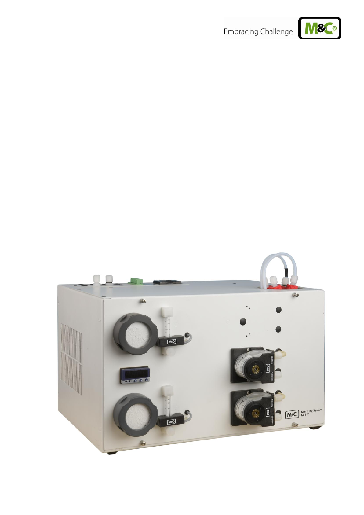
6 INTRODUCTION
The gas conditioning unit CSS-V.. for wall- or 19”-mounting is a completely pre-assembled compact
gas conditioning system, working continuously and delivering a sample gas quantity of max. 2 x
150Nl/hr resp. 1 x 250Nl/hr. A big variety of additional options guarantees an adaption to the different
requirements of continuous gas analysis technique.
The entire gas conditioning unit is housed in a compact and robust steel plate case which ensures that
the gas analyses can be carried out quickly, safely and with a minimum amount of maintenance.
The gas conditioning unit CSS-V.. must not be used for sampling of explosive gas/air or gas/oxygen
mixtures, for sampling of combustible gases which may result in an explosive mixture in combination
with air or oxygen nor in explosive atmospheres and hazardous areas.
4-1.2-ME Gas sampling and gas conditioning technology 7
Page 8
7 APPLICATION
The units CSS-V.. provide completely pre-installed sample gas conditioning for continuous use and
can excellently be integrated into gas analysis systems. Its compact construction means that it takes
up only little space. The CSS-V.. units are ready for use within a few minutes. This, at last, makes the
usual time-consuming procurement of individual components and assembly superfluous.
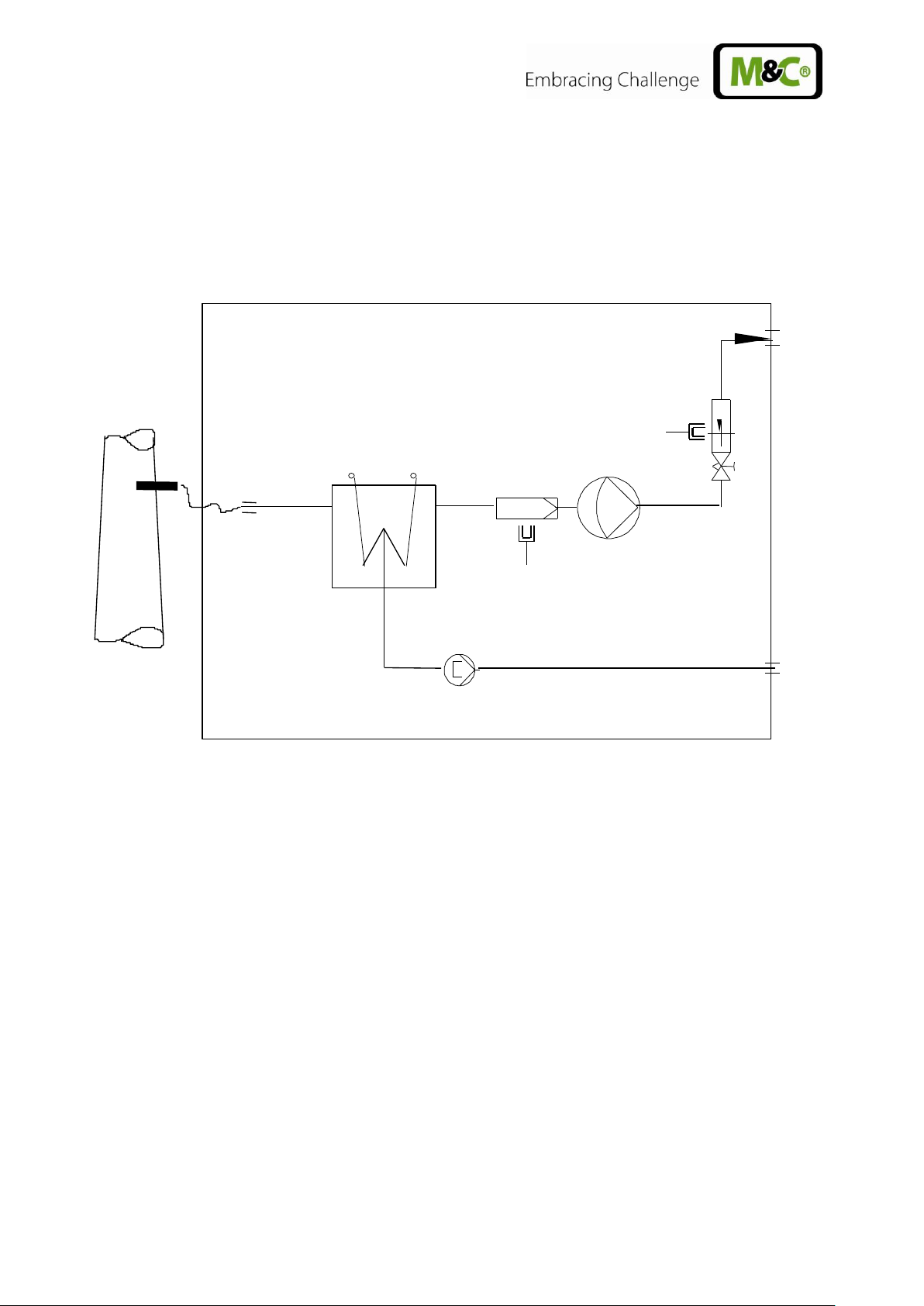
Figure 1 Scheme of gas flow CSS-V1..
Gas cooler ECM-1
Front panel filter FPF-2-0,3GF, 0,3µm porosity with integrated liquid alarm
Sample gas pump N3/5/9 KPE
Flowmeter FM40 with option flow alarm FM-20mo
Peristaltic pump SR25.2 for continuous automatic condensate removal
Way of sample gas tubed in PTFE.
Way of condensate tubed in Novopren®.
At the heat exchanger sample gas inlet and outlet are marked with arrows.
8 Gas sampling and gas conditioning technology 4-1.2-ME
Page 9
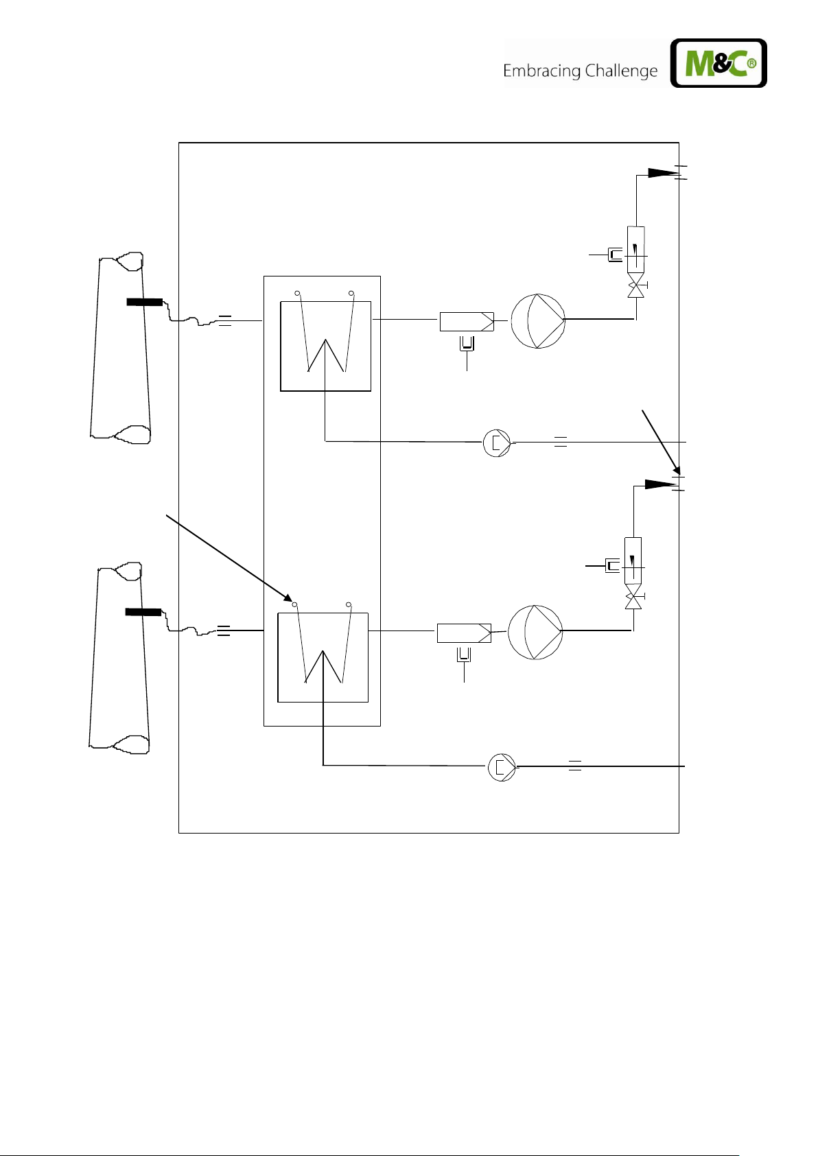
Marking with
black o-ring
Marking with
black o-ring
Figure 2 Scheme of gas flow CSS-V2..
Gas cooler ECM-2
2 x Front panel filter FPF-2-0,3GF, 0,3µm porosity with integrated liquid alarm
2 x Sample gas pump N3/5/9 KPE
2 x Flowmeter FM40 with option flow alarm FM-20mo
2 x Peristaltic pump SR25.2 for continuous automatic condensate removal
Way of sample gas tubed in PTFE.
Way of condensate tubed in Novopren®.
For differentiation the way of sample gas 2 is marked with a black o-ring at the sample gas inlet of the
heat exchanger 2 and sample gas outlet 2.
At the heat exchanger sample gas inlet and outlet are marked with arrows.
4-1.2-ME Gas sampling and gas conditioning technology 9
Page 10

Gas Conditioning Unit Type
CSS-V1
CSS-V2
Part No. 230V/50Hz
01G6010
01G6020
Part No. 115V/50-60Hz
01G6010a
01G6020a
Sample outlet dew point
Range of adjustment 2 … 7°C, factory setting +5°C
Dew point stability
at constant conditions < ±0,1 °C
Sample inlet temperature
**max. 180°C**
Gas inlet water vapour saturation
**max. +80°C
Gas flow rate
**max. 250l/h
**max. 2 x 150l/h
Ambient temperature
**+10°C to +40°C
Storage temperature
-25°C to +65°C
Pressure
0,7bar to 1,4bar abs.*
Total cooling capacity
max. 144kJ/h
Number of gas inlets
1
2
Number of gas outlets
1
2
Number of condensate outlets
1
2
Sample gas connections
Hose connection 4/6 mm
Material medium-touched parts
PVDF, PVC, Novoprene®, FPM, PPH, PTFE
Ready for operation
Approx. 10 min.
Mains power supply
230V 50-60Hz ± 10% or 115V 50-60Hz ± 10%
(115V/50Hz not with option sample pump)
Power consumption
max. 220VA + max: 300VA for the sample gas pumps
Fuse protection
4A, time-lag, 5x20mm
Electrical mains supply
Cold appliance plug with 2m cable
Case protection
IP20 (EN 60529)
Housing version
Sheet steel case foe 19”- or wall mounting, lacquered
RAL 7035
Case dimensions (H x W x D)
267,5mm x 483mm x 301,5mm
Weight
Approx. 22kg
8 TECHNICAL DATA
PVDF = Polyvinylidenefluoride
PVC = Polyvinyl chloride
FPM = Fluor caoutchouc
PPH = Polypropylene hard
PTFE = Polytetraflourethylene
* Standard
** Maximum values in technical data must be rated in consideration of total cooling capacity at 25°C
ambient temperature and 5°C outlet dewpoint.
10 Gas sampling and gas conditioning technology 4-1.2-ME
Page 11

Part No.
Description
93 K 0140
Extra charge for heat exchanger ECM- 1 out of glass
93 K 0170
Extra charge for heat exchanger ECM- 1 out of stainless steel SS316Ti
93 K 0160
Extra charge for heat exchanger ECM- 1 out of PVDF
97 K 0100
Extra charge for heat exchanger ECM- 2 out of Glas
97 K 0110
Extra charge for heat exchanger ECM- 2 out of stainless steel SS316Ti
97 K 0115
Extra charge for heat exchanger ECM- 1 out of PVDF
01 G 6125
Extra charge for mounting a sample gas pump N3 KPE
(additionally electronic controller 01G6150 necessary)
01 G 6130
Extra charge for mounting a sample gas pump N5 KPE
(additionally electronic controller 01G6150 necessary)
01 G 6135
Extra charge for mounting a sample gas pump N9 KPE
(additionally electronic controller 01G6150 necessary)
01 G 6120
Extra charge for mounting a sample gas filter FPF-2-0,3GF with integrated liquid
alarm sensor
09 F4000
Extra charge for mounting a flow meter FM40 7-70Nl/h
09 F 4005
Extra charge for mounting a flow meter FM40 15-150Nl/h
09 F 4010
Extra charge for mounting a flow meter FM40 25-250Nl/h
02 E 3500
Extra charge for mounting a flow alarm sensor FA-20mo
01 G 6150
Extra charge for mounting a control electronic for max. 2 liquid alarm sensors and
max. 2 flow alarm sensors
01 P 9125
Extra charge for mounting a peristaltic pump SR25.2 for condensate removal, with
complete tubing
8.1 OPTIONS
4-1.2-ME Gas sampling and gas conditioning technology 11
Page 12

9 DESCRIPTION
Figure 3 Design CSS-V2..
Fine filter FPF-2-0,3GF
Electronic controller
Flow meter FM40 with flow alarm sensor FA-20mo
Peristaltic pump SR25.2 with condensate outlet
Cold appliance socket
Connection for summery alarm
Sample gas outlets
Condensate outlet directly at the peristaltic pump
Sample gas inlet directly at the heat exchanger
All components of the gas conditioning unit are mounted in a compact sheet steel case. Filter and
peristaltic pump are placed into the front panel and thus assure a very easy maintenance.
The minimum flow is determined by the gas sampling pump (see also chapter 13). Premature damage
can be caused to the pump membrane if less than the minimal total amount of flow is extracted as a
result of excess pressure.
The gas cooler is equipped with a heat exchanger of Duran glass, stainless steel SS316Ti or PVDF.
The fine filter FPF-2-0,3GF (0,3µm filter fineness) installed in front of the sample gas pump
N3/5/9 KPE ensures the necessary removal of solid particles.
The instrument contains a temperature alarm contact that is activated in case the temperature differs
more than +/-3 °C from the set value (+ 5°C) adjusted at the factory and switches off the sample gas
pump if existing. The temperature alarm contact of the cooler (+8°C or +2°C) controls automatically
the switching on and off of the sample gas pump.
The condensate occurred is removed continuously via the peristaltic pump type SR25.2.
12 Gas sampling and gas conditioning technology 4-1.2-ME
Page 13

483
287,5
375,5
190,5
35,5
261,5
466
The DN4/6mm hose connections for the sample gas outlet as well as the electrical connections in the
top of the gas conditioning unit can, in dependence on the installation conditions, also be mounted in
the back of the unit very easily.
The ventilation grids in the sidewalls ensure that the equipment is sufficiently ventilated.
A liquid alarm sensor is integrated in the filter FPF-2-0,3GF to protect the downward analysers against
liquid irruptions and to increase the operating safety of the whole system. In case of liquid inrush, the
sample gas pump, if existing, is switched off automatically.
Figure 4 Dimensions CSS-V..
4-1.2-ME Gas sampling and gas conditioning technology 13
Page 14

NOTE!
The gas conditioning system should be stored in a protected frost-free area !
NOTE!
In order to ensure that the case is safe and stable when being used, it should
be placed on a horizontal surface free from vibrations. Only then, the perfect
functioning of the separation and drainage procedures of the condensate
inside the heat exchanger of the cooler will only be guaranteed.
The gas conditioning system should be kept away from heat sources and be
freely ventilated in order to prevent an accumulation of heat.
When the equipment is being used outside, ample protection against the
effects of direct sunlight and dampness must be provided. In winter, the
equipment must only be used in frost-free areas; pay attention to the type of
the equipment protection.
Please avoid temperature variations, strong airflow as well as aggressive
atmospheres at the place of installation.
In order to guarantee the operational safety of the gas conditioning system
and the downstream analysers, and to avoid false alarms, the gas
conditioning unit should not be used at temperatures other than those
specified. Furthermore, it must be protected against dust deposits and
penetrating dust.
It is of great importance that the analysers connected downstream are used
at temperatures well above the specified gas outlet dew point of +5°C. This
prevents the gas in the connector lines to the analysers from subsequent
condensing.
Unheated gas sample lines must be installed with slope up to the cooler.
10 RECEIPT OF MARCHENDISE AND STORAGE
The gas sampling system CSS-V.. is a completely pre-installed unit. The scope of delivery includes
furthermore:
25 Filter elements (1 pckg.)
1 Connection cable
1 6-pole connection box
1 Operating Manual
Please take the CSS-V.. and possible special accessories carefully out of the packaging material
immediately after arrival, and compare the goods with the items listed on the delivery note;
Check the goods for any damage caused during delivery and, if necessary, notify your transport
insurance company without delay of any damage discovered.
11 INSTALLATION INSTRUCTIONS
14 Gas sampling and gas conditioning technology 4-1.2-ME
Page 15

NOTE!
Do not mix up the hose connections.
After having connected all lines, please check the seals.
11.1 RETROFITTING OF THE WALL MOUNTING HOUSING TO A 19“-HOUSING
The gas conditioning units CSS-V.. are delivered with a wall mounting housing.
If a 19”-housing is needed, the gas conditioning unit can be backfitted very easy by installing the
mounting brackets from the back to the front:
Dismount the two fixing screws at each mounting bracket
Adjust the mounting bracket with 19“-bore holes forward-turned
Fix the mounting bracket flush with the front panel at the housing by using the two fixing
screws
12 SUPPLY CONNECTIONS
12.1 HOSE CONNECTIONS
Figure 5 Hose connections CSS-V
Contrary to figure 4 execution CSS-V2 has two sample gas outlets.
The condensate connections are carried out directly at the peristaltic pump.
All hose connections are DN4/6mm sealing ring threaded hose couplings out of PVDF/PPH as
standard. They are suitable for gas inlet temperatures of maximum 80°C (see chapter 8).
4-1.2-ME Gas sampling and gas conditioning technology 15
Page 16

NOTE!
The tightness of the connections can only be guaranteed if the connecting
hose has a straight edge (use a hose cutter).
WARNING!
Aggressive condensate is possible.
Wear protective glasses and proper protective clothing!
WARNING!
False supply voltage can damage the equipment. When connecting
the equipment, please ensure that the supply voltage is identical
with the information provided on the model type plate!
The mounting of the sample gas hoses and the condensate hoses is to be executed as follows:
Remove the union nut from the sealing ring couplings by turning it anti-clockwise. The nut should
be removed from the thread with great care so as to ensure that the loose sealing ring in the nut is
not lost.
Place the union nut over the connecting hose.
Push the sealing ring over the connecting hose with the thicker bead towards the nut.
Place the hose over the nipple on the thread.
The union nut is to be screwed tight by hand.
The hose will no longer be able to slip off, and is now compression-proof.
The hoses are to be removed in the reverse order.
12.2 DISPLACE THE CONNECTIONS TO THE BACK OF THE HOUSING
If the installation conditions necessitate to displace the connections to the back of the housing, this is
possible very easily:
Remove connection sheet fixing screws (see Fig.4)
Remove cover angle fixing srews at the back of the unit
Install connection sheet with 2 fixing screws at the back of the unit
Install cover angle with 2 fixing screws at the top of the housing
12.3 ELECTRICAL CONNECTIONS
16 Gas sampling and gas conditioning technology 4-1.2-ME
Page 17

NOTE!
For the assembly of power installations with rated voltages up to
1000V, the requirements of VDE 0100 and relevant standards and
specifications must be observed!
The main circuit is equipped with a fuse corresponding to the
nominal current (over current protection); for electrical details see
technical data (chapter 8).
1 2 3 4 5 6 Intern
Extern
Status Alarm
Kontaktbelastung
Contact rating
24V AC/DC 0,5A
Stecker/male connector Typ Phoenix MSTB
2,5/6-STF 5,08
Oberer Kanal
Unterer Kanal
Buchse/Female X2
Lower channel
Upper channel
The gas conditioning unit CSS-V is available with either 230V/50 Hz or 115V/50-60Hz (for circuit
diagram see Appendix). 4A fuses are used on all models as fuse protection. The fuses are located
inside of the cold appliance socket.
The electrical connection is made via the 2m mains cable with cold appliance plug optionally at the
back side or the top of the housing.
Connection of the signal lines:
The electrical connection of the summery alarm (cooler, liquid and flow) is made via the 6-pole
connection box optionally at the back or top of the housing.
The adequate 6-pole plug is part of the scope of delivery .
The plug is connected as follows:
Figure 6 Plug connections summery alarm
For CSS-V1 the summery alarm of the lower channel is connected (4, 5, 6).
For CSS-V2 both channels are connected with the cooler alarm as well as with a liquid and a flow
alarm each.
4-1.2-ME Gas sampling and gas conditioning technology 17
Page 18

HINWEIS!
Please install the signal lines separated from the power supply
lines.
NOTE!
The request for a maximum pressure load of the sample gas pump of 1,4 bar
abs. results in the following minimal gas flow rates:
N 3 KPE min. 30l/h air
N 5 KPE min. 60l/h air
N 9 KPE min. 110l/h air
Premature damage can be caused to the pump membrane due to excess
pressure if less than the minimal total amount of flow is extracted.
In case of long-term measurements with a high level of dust, it is necessary
to utilise a suitable sample gas probe in order to protect the sample leads
from clogging-up.
Indication
LED K1
LED K2
After starting up
> 8°C
(Ambient temp.)
Off (Status alarm and pump
off)
Beaming permanently
yellow (cooling)
After approx. 10 min.
7,5°C
Beaming yellow.
In case no condensate alarm
is given and the pump switch
is activated (beaming green),
the pump will be switched on.
Sample gas is lifted.
Beaming permanently
yellow
(cooling)
Normal operation
5°C
Beaming yellow
Beaming yellow
(Regulation of the
cooler)
13 STARTING
Before starting the gas conditioning system, pay attention to the site-oriented and process-oriented
precautions. Please check once again that the operating voltage (see type plate) corresponds with
the supply voltage!
The following steps have to be done before starting up for the first time:
Place the cold appliance plug, which is delivered with the mains supply cable, into the cold
appliance plug socket;
Connect the mains plug to the mains;
Switch on power.
After the starting time (LED K1 on the controller is beaming), the gas conditioning system is ready for
use, and the sample gas pump is switched on. Only now the sample gas can be be fed.
13.1 COOLER REGULATION
18 Gas sampling and gas conditioning technology 4-1.2-ME
Page 19

NOTE!
The location for the gas conditioning unit must remain frost-free, even if the
unit has been switched off.
WARNING!
Aggressive condensate possible.
Wear protective glasses and proper protective clothing!
WARNING!
Dangerous voltage. Before any maintenance work is carried out on
the gas conditioning system, disconnect the unit from the mains !
NOTE!
In order to protect downstream analysers in case of a irruption of
condensate, always replace the humid filter element.
14 CLOSING DOWN
There are no special regulations to be observed if the gas conditioning unit CSS-V is to be closed
down for a short period of time.
In case of a long-term closing down, for example after a series of measurements has been completed,
it is recommended to purge the gas conditioning system with ambient air or inert gas. Under normal
conditions, the equipment needs only to be washed for 3 to 5 minutes. Condensate residues should
also be removed from the system.
15 MAINTENANCE
Before carrying out any maintenance work, the specific safety instructions referring to the instalment
and the process must be observed!
The frequency of the maintenance work depends on the operational process and can therefore only
be determined in each individual case.
All parts which require maintenance work are easily accessible and are installed on the front side of
the gas conditioning unit CSS-V. Only for any work on the gas sample pump, the case has to be
opened:
Replace the filter element of the fine filter FPF-2-0,3 GF in case the flow rate is to low or after
visible control (see chapter 15.1).
The diaphragm of the sample gas pump N3/5/9 KPE should be checked every six months and, if
necessary, replaced (see chapter 15.2).
4-1.2-ME Gas sampling and gas conditioning technology 19
Page 20

NOTE!
In any case you open the filter, the filter element has to be changed.
The hose of the condensate pump SR25.2 should be checked every six months and, if necessary,
replaced (see chapter 15.3.1);
Remove dust periodical from the cooling fins with pressure air (see chapter 15.4)
15.1 REPLACEMENT OF THE FILTER ELEMENT AND THE O-RING
For changing the filter element and the O-ring:
Disconnect the mains voltage;
Unscrew the filter housing cover;
Exchange the filter element and/or O-ring. Pay attention to the correct insertion of the filter
element and the O-ring (the structural surface of the filter element has to be forward turned!).
Screw down the filter housing cover again.
Figure 7 Replacement of the filter element and the O-ring
20 Gas sampling and gas conditioning technology 4-1.2-ME
Page 21
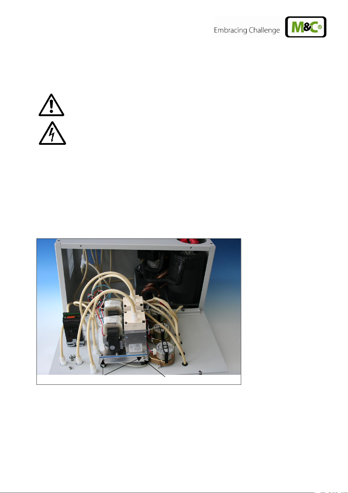
WARNING!
Dangerous voltage. Before any maintenance work is carried out on
the gas conditioning system, disconnect the unit from the mains !
fixing screws
mounting angle
15.2 DISMOUNTAGE OF THE SAMPLE GAS PUMP FOR EXAMINATION OR
MAINTENANCE
For dismounting the sample gas pump N3/5/9 KPE:
Disconnect the gas conditioning system from the mains voltage;
Unscrew the 4 screws at the front panel, open the front lightly without detaching the piping and
the wiring and remove the front panel upwards;
Loosen the 4 fastening screws of the mounting angle on which the pump is mounted (see Fig.
7);
Remove piping from the pump head;
Pull out the pump with mounting angle;
Examination and maintenance of the pump with help of the manual N3/5/9 KPE (the manual is
part of the provided manual or for a download on our homepage: www.mc-techgroup.com);
After examination and maintenance screw the mounting angle again and mount the front panel.
Figure 8 Dismountage of the sample gas pump
15.3 MAINTENANCE OF THE INTEGRATED PERISTALTIC PUMP TYPE SR 25.2
Pump hose, moving strap, pressure roller and springs are the only wearing parts of the pump. They
are easily to exchange.
4-1.2-ME Gas sampling and gas conditioning technology 21
Page 22

WARNING!
Aggressive sample residues possible.
Wear protective glasses and proper protective clothing during
dismountage, repair or cleaning of the peristaltic pump!
NOTE!
In case you send the peristaltic pump to the M&C Service
Department, please indicate what medium has been lifted.
Before returning the pump to M&C, it must be cleaned from
dangerous or highly aggressive contaminations.
WARNING!
Only when using the original spare pump hose, the perfect function
is guaranteed.
Never grease the pump hose.
Before assembling the peristaltic pump, examine all parts for
contaminations and if necessary clean them.
15.3.1 REPLACEMENT OF THE PUMP HOSE
Figure 9 Replacement of the pump hose
Disconnect the gas conditioning system from the mains voltage;
Loosen the hose connections on the pump;
Press the moving strap on the recessed grips and turn the S-bar clockwise as far as the
limit stop;
Take out the moving strap and pull the old pump hose on the hose nozzles out of the
guides;
Press the pressure rollers and check whether there is any tension on the springs, if not,
exchange the pressure springs (see chapter 15.3.2);
Place the new pump hose with the hose nozzles into the guides of the moving strap ;
Put he moving strap with the new hose completely into the dovetail guide of the pump
body; press the moving strap on the recessed grips and turn at the same time the S-bar
anticlockwise as far as it locks into place;
Turn the pump on.
22 Gas sampling and gas conditioning technology 4-1.2-ME
Page 23

NOTE!
The springs may occur in different coulerings. This does not constitute a
quality defect. But make sure that the right spring strength is used. This
can be identified by the spring wire diameter. The „standard version for
Novoprene pump hoses“ (part no. 90P1010) has a diameter of 1,1mm and
the strengthened version for FPM-, Acidflex- or Masterflex-hoses“ (part
no. 90P1015) has a diameter of 1,2mm.
The dent prevents
rotation of the axis
new
worn out
15.3.2 CHANGE OF CONTACT PULLEYS AND SPRINGS
Switch off the mains;
Unscrew nuts of the pump head (wrench size 5,5) and remove snap ring from motor
shaft;
Figure 10 Disassembly of pump head and driver
Draw the pump head out of the motor shaft
Take driver out of the pump head
The removal of the springs (4 pcs.) away from the driver is easily possible without the aid of
any tools. For this take spring out of the groove near to the shaft bore.
Dismount roller axes and change contact pulleys. Take care that axes are not worn out by the
springs and have damaged the dent at the axes front end. In case of abrasion the axes have to
be changed (see Figure 11).
Figure 11 Check of axes and rolls
4-1.2-ME Gas sampling and gas conditioning technology 23
Page 24

NOTE!
At first delivery two different types of springs are mounted in the driver
(right and left springs). When spare springs are ordered, for simplified
storage only one type will be delivered (right spring) that can be replaced
without any problems and guarantees full functionality when all four
springs are replaced.
NOTE!
While mounting pay attention to the fit of ‘rotational axisdriver’ and
check that the plunged boss at the shaft bore points to the front of the
pump head.
Use genuine spare parts only !
WARNING!
Aggressive medium residues possible.
During dismountage, rapair or cleaning of the pump, wear
protective glasses and proper protective clothing!
NOTE!
With clean cooling fins a DIN A4 sheet of paper is sucked in and
clings to the right side of the housing.
Make sure that contact pulleys roll easily on the axis. After remounting the axis with contact
pulley into the driver the spring has to be mounted as shown in Figure 11. Please pay attention
to the alignment of the dent.
Remounting happens in reverse order.
15.3.3 CLEANING OF THE PUMP HEAD
We recommend to clean the single parts with a dry cloth. Principally, you should not use any
solvents for cleaning because they could affect the synthetic material. In case there is oil-free
compressed air available, the parts can be blown through.
15.4 CLEANING THE COOLING FINS OF THE COMPRESSOR COOLER
To prevent a decrease of the cooling capacity the cooling fins have to be cleaned from dust periodical.
For this purpose blow compressed air into the ventilation grid at the right side of the housing.
24 Gas sampling and gas conditioning technology 4-1.2-ME
Page 25

16 OPERATING OF THE INTEGRATED ELECTRONIC TEMPERATURE REGULATOR
During normal operation, the display of the temperature regulator shows the actual cooling
temperature.
Figure 12 Front view of the temperature regulator
16.1 CHANGING THE SET VALUE
For changing the set value, press the P-button < 2s. The set value, adjusted at the factory to 5°C, is
shown. With both arrow keys, the set value can be set upwards or downwards. However, this value
should not be adjusted below +2°C, otherwise freezing up of the heat exchanger is possible. If the
value is set above ambient temperature, the cooler will not work.
4-1.2-ME Gas sampling and gas conditioning technology 25
Page 26

Display
Fault
Possible cause
Examination/Correction
None
No supply voltage;
Check the supply voltage according to the type
plate;
ok?
Control whether the mains plug is put in correctly;
ok?
Examine the fine fuses F1, F2 in the cold appliance
socket;
ok?
LED K1 is
beaming
permanently
and temp. > 8°C
Cooler alarm „Excess
temperature“; cooler
switches off the
sample gas pump
automatically if
existing;
Ventilator does not
function
Ambient temperature too high;
ok?
Free convection inside the gas conditioning unit
upset internal temperature too high;
ok?
Sample flow or dew point too high? Reduce flow.
ok?
Return the instrument for repair to M&C.
Temp.
>2°C and
< 7,5°C
Cooler runs,
sample flow is
interrupted;
Pump
defective
Diaphragm pump
does not work;
Liquid alarm sensor:
Sensor turns sample
gas pump
automatically off;
LED Liquid alarm is beaming red.
Liquid in the filter (Dry filter and liquid alarm sensor
and check peristaltic pump, see below.)
ok?
Check the hoses for condensate draining;
ok?
Check pump hose (see 15.3.1);
ok?
Check pump SR25.2 (see 15.3);
ok?
Return instrument for repair to M&C.
Pump works,
but sample
gas flow is
interrupted;
Flow meter :
Needle valve is shut.
Sample probe or
sample hose clogged
or line squeezed;
Set the desired flow rate on the needle valve.
Loosen the sample hose from the sample gas inlet
of the gas conditioning unit (see 12.1);
Gas flow?
Clean the clogged line or replace it;
17 TROUBLE SHOOTING
The following table shows possible sources of errors and how to remove them (not applicable for the
starting-up phase).
26 Gas sampling and gas conditioning technology 4-1.2-ME
Page 27

Sample line to the
analyser clogged or
squeezed;
Pollution of the
diaphragm pump;
No gas flow?
Loosen the outlet hose on the analyser side and
check on the threaded hose coupling whether
sample gas flows;
Sample gas does not flow?
Clean the clogged line or replace it;
Sample gas flows?
ok?
Loosen the piping on the pump head and examine
it (see 15.2);
ok?
If necessary, clean the pump;
Ok?
Temp.
<2°C
Cooler switches off
the sample gas pump
automatically;
Cooler defective;
Ambient temperature too low;
ok?
Return the instrument for repair to M&C.
4-1.2-ME Gas sampling and gas conditioning technology 27
Page 28

Gas Conditioning Unit Version CSS-V
(V) Consumables, (E) Recommended Spare Parts and (T) Spare Parts
Recommended quantity after
operation of [years]
Part No.
Description
C/R/S 1 2
3
Fine filter FPF-2-0,3GF
90 F 0160
Filter element type F-2-0,3GF. Material:
glass fiber, porosity: 0,3µ 25 pcs./pack.
C 1 2
3
90 F 0167
O-ring FPF-2/54. Material: Viton.
R 1 1
1
Peristaltic pump SR25.1:
90 P 1007
SR25 pump hose with threaded hose
coupling of PVDF, DN 4/6mm
C 1 2
4
90 P 1010
1 set contact spring for driver of peristaltic
pump R25.2, (set = 4 pcs.)
C 1 2
3
90 P 1020
Driver complete for peristaltic pump SR25.2
R
1
90 P 1045
Contact pulley (1 pc.) for peristaltic pump
SR25.2, (2 pcs./pump required).
C 2
4
Diaphragm pump type N3/5/9 KPE
90P2100
Square cap type D3, 1/8“i for
N3/N5 KPE/KP18. Material: PVDF
S - -
1
90P2120
Diaphragm type S3, for
N3/N5 KPE/KP18,
Material: Viton, PTFE coated
C 1 2
3
90P2115
O-ring type O3, for N3/N5 KPE/KP18,
1 pc., Material: Viton (2 pcs. Required)
C 2 4
6
90P2110
Valve plate type V3, for N3/N5 KPE/KP18,
1 pc., Material: Viton (2 pcs. Required)
C 2 4
6
90P2105
Intermediate plate type Z3, for
N3/N5 KPE/KP18, Material: PVDF
S - -
1
90 P 2220
Diaphragm type S9, for
N9 KPE/KP18,
Material: Viton, PTFE coated
C 1 2
3
90 P 2211
Valve plate with seal for N9 KPE, 1 pc.,
material: Viton. (2 pcs./pump)
C 2 4
6
90 P 2205
Intermediate plate type Z9, for
N9 KPE/KP18, Material: PVDF
S - -
1
90 P 2200
Square cap type D9, 1/8“i for
N9 KPE/KP18. Material: PVDF
S - -
1
18 SPARE PART LIST
Wear, tear and replacement part requirements depend on specific operating conditions.
The recommended quantities are based on experience and are not binding.
28 Gas sampling and gas conditioning technology 4-1.2-ME
Page 29

Flow meter FM40:
90 A 0015
Flow meter glass for FM40
Measuring range 7-70 l/h air
S - 1
1
94 F 0010
Flow meter glass for FM40
Measuring range 15-150 l/h air
S - 1
1
94 F 0015
Flow meter glass for FM40
Measuring range 25-250 l/h air
S - 1
1
90 A 0018
Viton O-ring 9 for FM40 glass
R 2 4
6
Miscellaneous:
90 K 6030
Fine fuse 4A T, 5x20mm for CSS...
R 5 5
5
Hose and threaded hose couplings:
05 V 3215
Bulkhead union SV-PVDF DN 4/6
R 2 2
2
05 V 6600
Ferrule 4/6 PVDF s.a.
R 5 10
10
05 V 6605
Union nut M10-4/6 PVDF s.a.
R 5 10
10
01 T 1000
Viton tube NW 4/6 (m)
S 1 2
3
10 T 1000
Hose cutter
S 1 1
1
4-1.2-ME Gas sampling and gas conditioning technology 29
Page 30

19 APPENDIX
Connecting conductors board CSS-V
For further product documentation, please see our internet catalogue:
www.mc-techgroup.com
Instruction manual peristaltic pump SR25.1, SR25.1-G,
document : 3-7.1-ME
Instruction manual diaphragm pump series N
document : 6-1.2.1-ME
Flowmeter FM 40,
document : 5-6.1.10
30 Gas sampling and gas conditioning technology 4-1.2-ME
Page 31

Figure 13 Connecting conductors board CSS-V
4-1.2-ME Gas sampling and gas conditioning technology 31
 Loading...