

Page 1
CSS-V2
Embracing Challenge
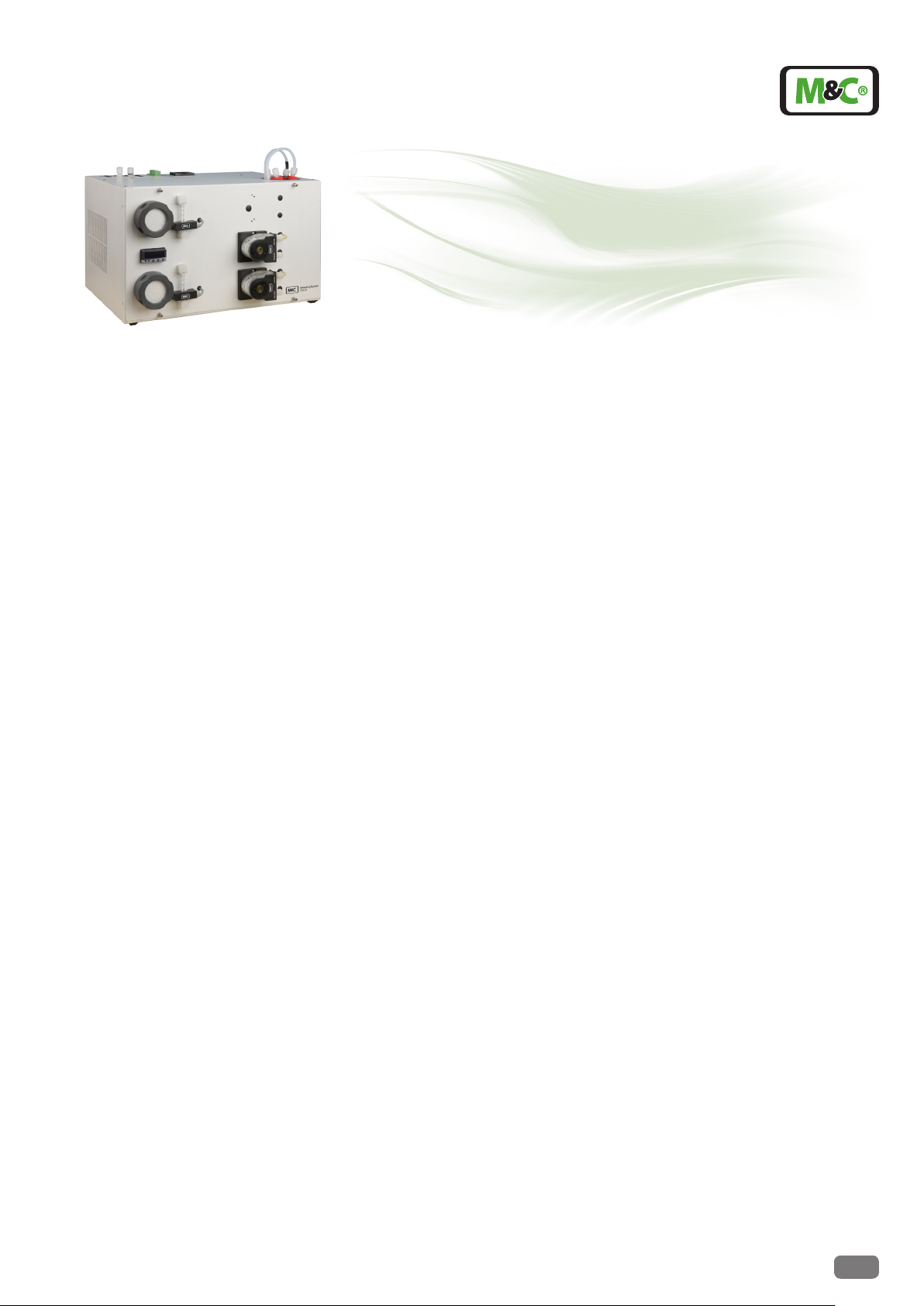
Gas Conditioning Unit series CSS®
Version CSS-V1 for max. 1 x 250Nl/h gas ow rate,
Version CSS-V2 for max. 2 x 150Nl/h gas ow rate,
for 19”- or wall mounting
Special Features
Compact high-performance construc-
tion with compressor cooler
Individually congurable
Completely pre-installed
One or two gas streams
19”- or wall mounting housing
Low maintenance and self-monitoring
Outlet dew point adjustable from +2 °C
to +7 °C
Dew point stability ± 0,1°C
Operational in 10 minutes
Light weight
Optimum reliability
Application
The units CSS-V.. provide a complete preinstalled compact high-performance sample
gas conditioning for continuous use. Due to a
big variety of additional options the gas conditioning units excellently can be adapted to
the most diverse requirements of gas analysis
technique.
Its compact construction only takes up little
space. The CSS-V units are ready for use in a
few minutes. This makes time-consumingprocurement of individual components and
assembly superfluous.
Description
All components of the gas conditioning unit
are mounted in a compact sheet steel case.
Filter, flowmeter and peristaltic pump are
placed into the front panel and thus assure a
very easy maintenance.
The compressor gas cooler is equipped with
one or two heat exchangers of Duran glass,
stainless steel SS316Ti or PVDF.
The fine filter FPF-2-0,3GF (0,3µm filter fineness) installed in front of the sample gas
pump N3/5/9 KPE ensures the necessary
removal of solid particles. The condition of
the filter element is visible from outside.
The downstream installed sample gas pump
N3/5/9 KPE is available with 3 pump capacities.
The flow meter FM40 with corresponding
measuring range installed in the sample gas
outlet can be equipped with a flow alarm
sensor FA-20mo and the adequate electronic.
The unit contains a temperature alarm contact that is activated in case the temperature
differs more than +/-3 °C from the set value (+
5°C) adjusted at the factory and switches off
the sample gas pump if existing.
The condensate occurred is removed continuously via the peristaltic pump type SR25.2.
The ventilation grids in the sidewalls ensure
that the equipment is sufficiently ventilated.
A liquid alarm sensor is integrated in the filter
FPF-2-0,3GF to protect the downstream analysers against liquid irruptions and to increase
the operating safety of the whole system. Via
one or two potential free contacts for the
summery alarm (cooler temperature, gas flow,
liquid) an alarm is indicated and the sample
gas pump, if existing, is switched off.
Technical specications and illustrations are without
obligation, subject to modications. 11.08/11.12
M&C TechGroup Germany GmbH • Rehhecke 79 • 40885 Ratingen • Germany
info@mc-techgroup.com • www.mc-techgroup.com • Fon +49 2102 935-0 • Fax +49 2102 935-111
14.1
Page 2

1
2
5
2
5
4
3
4
3
Design CSS-V1
1 Gas cooler series ECM-1
2 Option front panel lter FPF-2-0,3GF, 0,3µm
lter unit with integrated liquid alarm
3 Option sample gas pump N3/5/9KPE
4 Option owmeter FM40 with ow alarm
5 Option peristaltic pump SR25.2
Design CSS-V2
1 Gas cooler series ECM-2
2 Option front panel lter FPF-2-0,3GF, 0,3µm
lter unit with integrated liquid alarm
3 Option sample gas pump N3/5/9KPE
4 Option owmeter FM40 with ow alarm
5 Option peristaltic pump SR25.2
1
4
2
3
5
Dimensions CSS-V..
14.1
M&C TechGroup Germany GmbH • Rehhecke 79 • 40885 Ratingen • Germany
info@mc-techgroup.com • www.mc-techgroup.com • Fon +49 2102 935-0 • Fax +49 2102 935-111
1 Fine filter FPF-2-0,3GF
2 Electronic controller
3 Flow meter FM40 with flow alarm sensor
FA-20mo
4 Peristalltic pump SR25.2
5 Power supply
6 Connection collective alarm
7 Sample gas outlets
8 Condensate outlet at the peristaltic pump
9 Sample gas inlets at heat exchanger
Technical specications and illustrations are without
obligation, subject to modications. 11.08/11.12
Page 3

Technical Data
Gas Conditioning Unit series CSS
®
version CSS-V1 version CSS-V2
Part No. for 230V 50Hz version 01G6010 01G6020
Extra charge 115V/50-60Hz 01G6160
Sample outlet dew point range of adjustment: +2 °C ..... +7 °C, factory setting: +5 °C
Dew point stability at constant conditions < ±0,1 °C
Sample inlet temperature **max. 180 °C
Sample inlet dew point **max.+80 °C
Gas flow rate **max. 250 Nl/hr **max. 2 x 150 Nl/hr
Ambient temperature **+5 °C up to +40 °C
Storage temperature -25 °C up to +65 °C
Pressure 0,7 bar up to 1,4 bar abs.
Total cooling capacity ** max. 144 kJ/hr
Number of gas inlets 1 2
Number of gas outlets 1 2
Condensate outlet 1 2
Medium connections tube connection 4/6 mm
Material of sample contacting parts PVDF, Novoprene®,FPM, PVC, PPH, PTFE
Ready for operation approx. 10 min.
Power supply 230V 50-60Hz ±10% or 115V 50-60Hz ±10% (115V/50Hz not with option sample pump)
Power consumption max. 220VA + max. 300VA for the sample gas pump
Fuse protection 4A t, 5x 20 mm
Electrical connection Cold appliance plug with 2 m of cable
Case protection IP20 EN 60529
Sheet steel housing, execution sheet steel case for 19"- or wall mounting, lacquered RAL 7032
Equipment dimensions 267,5 mm x 483 mm x 301,5 mm (H x W x D)
Electrical equipment standard EN61010
Weight approx. 22 kg
PVDF = Polyvinylidenuoride
PVC = Polyvinylchloride
FPM = Fluor caoutchouc = Viton
PPH = Polypropylene hard
PTFE = Polytetraourethylene
** Maximum values in technical data must be rated in consideration of total cooling power at 25 °C and an outlet dew point of +5°C.
®
Options
Description Part No.
Extra charge for heat exchanger ECM-1 out of glass 93K0140
Extra charge for heat exchanger ECM-1 out of stainless steel SS316Ti 93K0160
Extra charge for heat exchanger ECM-1 out of PVDF 93K0170
Extra charge for heat exchanger ECM-2 out of glass 97K0100
Extra charge for heat exchanger ECM-2 out of stainless steel SS316Ti 97K0115
Extra charge for heat exchanger ECM-2 out of PVDF 97K0110
Extra charge for mounting the sample gas pump N3KPE (additionally electronic controller 01G6150 necessary) 01G6125
Extra charge for mounting the sample gas pump N5KPE (additionally electronic controller 01G6150 necessary) 01G6130
Extra charge for mounting the sample gas pump N9KPE (additionally electronic controller 01G6150 necessary) 01G6135
Extra charge for mounting a sample gas filter FPF-2-0,3GF with integrated liquid alarm sensor 01G6120
Extra charge for mounting a flow meter FM40 7-70Nl/hr 09F4000
Extra charge for mounting a flow meter FM40 15-150Nl/hr 09F4005
Extra charge for mounting a flow meter FM40 25-250Nl/hr 09F4010
Extra charge for mounting a flow alarm sensor FA-20mo 02E3500
Extra charge for mounting a peristaltic pump SR25.2 for condensate removal, completely flexible tubed 01G6140
Extra charge for mounting an electronic controller for max. 2 liquid alarm sensors and max. 2 flow alarm sensors 01G6150
Order example:
1x 01G6010 + 1x 93K0140 + 1x 01G6125 + 1x 01G6120 + 1x 09F4010 + 1x 02E3500 + 1x 01G6140 + 1x 01G6150 = CSS-V1 , 230V, with heat
exchanger out of glass, built-in sample gas pump N3KPE, sample gas filter FPF-2-0,3GF with integrated liquid alarm sensor, flowmeter FM40
25-250Nl/h and flow alarm sensor FA-20mo, peristaltic pump SR25.2 for condensate removal and electronic controller for liquid and flow
alarm sensor.
Technical specications and illustrations are without
obligation, subject to modications. 11.08/11.12
M&C TechGroup Germany GmbH • Rehhecke 79 • 40885 Ratingen • Germany
info@mc-techgroup.com • www.mc-techgroup.com • Fon +49 2102 935-0 • Fax +49 2102 935-111
14.1
 Loading...