

Page 1
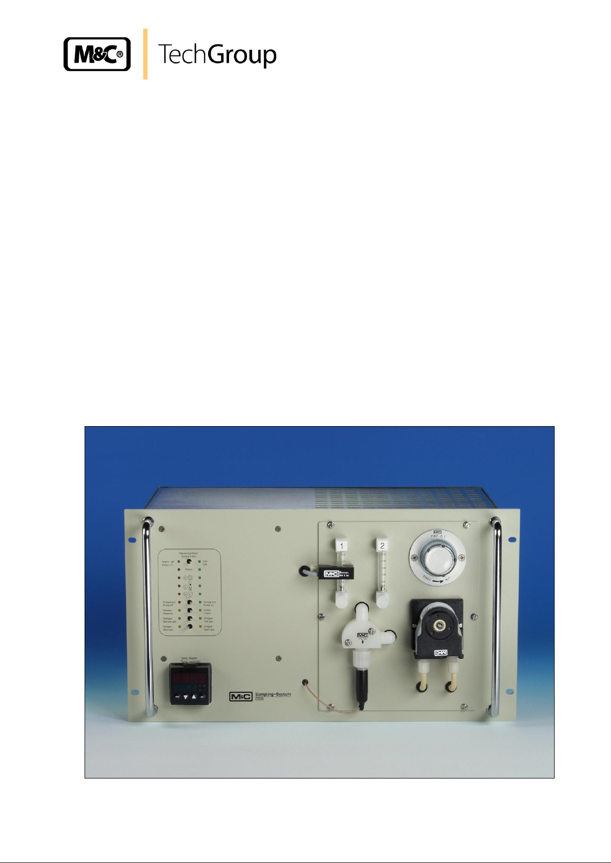
Operating Manual
19 Inch Rack Mounting Gas Conditioning Unit
series CSS
®
(incl. the new temperature controller type 70304)
Gas sampling and gas conditioning technology 4-1.1-ME
Page 2

2
List of contents
1 General information ................................................................................................................... 5
2 Declaration of conformity .......................................................................................................... 5
3 Safety instructions ..................................................................................................................... 6
4 Warranty ...................................................................................................................................... 6
5 Used terms and signal indications ........................................................................................... 7
6 Introduction ................................................................................................................................. 8
6.1 Serial number ........................................................................................................................... 8
6.2 Power supply ............................................................................................................................ 8
7 Technical Data ............................................................................................................................ 9
8 Description ................................................................................................................................ 10
9 Function .................................................................................................................................... 16
10 Electrical Connections ............................................................................................................. 18
10.1 Electrical junction box X1 ....................................................................................................... 18
10.2 Sub-D-plug X2 ........................................................................................................................ 19
10.2.1 Status contacts ................................................................................................................. 19
10.2.2 Local control ..................................................................................................................... 20
10.2.3 External Control ................................................................................................................ 21
10.3 Liquid- and flow alarm card LFC-2 ......................................................................................... 22
11 Description of the optional temperature controller 70304 for heated sample lines ........... 24
12 Operating principle of the controller 70304 ........................................................................... 24
12.1 Parameter of the user level with factory setting ...................................................................... 24
13 Change of parameters .............................................................................................................. 25
13.1 Removing and activating the level inhibit ............................................................................... 25
13.2 Menue structure...................................................................................................................... 26
13.3 Time Out ................................................................................................................................. 26
14 Receipt Of Goods and storage ................................................................................................ 27
15 Installation instructions ........................................................................................................... 27
16 Supply connections ................................................................................................................. 28
16.1 Hose connection ..................................................................................................................... 28
16.2 Electrical connections ............................................................................................................. 28
17 Starting ...................................................................................................................................... 29
17.1 Measure.................................................................................................................................. 29
17.2 Check/Calibration ................................................................................................................... 30
17.3 Self-optimising (PID-Function) of the controlled system ......................................................... 31
18 Closing down ............................................................................................................................ 31
19 Maintenance .............................................................................................................................. 32
20 Dismounting the flow components sub panel ....................................................................... 32
21 Alarms and elimination ............................................................................................................ 33
21.1 Voltage loss ............................................................................................................................ 33
21.2 Cooler alarm/temperature controller alarm ............................................................................. 34
21.3 Flow alarm .............................................................................................................................. 34
21.4 Liquid alarm ............................................................................................................................ 35
22 Spare part lists .......................................................................................................................... 36
23 Appendix ................................................................................................................................... 38
Gas sampling and gas conditioning technology 4-1.1-ME
Page 3

3
List of illustrations
Figure 1 Front view of the CSS ...................................................................................................... 10
Figure 2 Operation and control board............................................................................................. 11
Figure 3 Plan view of the components mounted on the Flow components sub panel .................... 13
Figure 4 Components mounted in the 19“ rack housing ................................................................. 14
Figure 5 Back-panel of the 19" rack housing .................................................................................. 15
Figure 6 Gas flow schematic .......................................................................................................... 16
Figure 7 Electrical junction box X1 (B) ........................................................................................... 18
Figure 8 Status contacts ................................................................................................................. 19
Figure 9 Plan of terminal connections in the Sub-D-Plug X2 (A) for local control of the
CSS... and CSS.../C ......................................................................................................... 20
Figure 10 Plan of terminal connections in the Sub-D-Plug X2 (A) for external control of
the CSS... and CSS.../C ................................................................................................... 21
Figure 11 Circuit diagram LFC-2 ...................................................................................................... 23
Figure 12 Display/control elements .................................................................................................. 24
Figure 13 Menue structure ............................................................................................................... 26
Figure 14 Pin assignment for external drive of the CSS ................................................................... 39
Figure 15 Circuit diagram gas conditioning CSS .............................................................................. 40
Figure 16 CSS with 4 x span solenoid valves .................................................................................. 41
Gas sampling and gas conditioning technology 4-1.1-ME
Page 4

4
This Operating Manual does not claim completeness and may be subject to technical modifications.
© 10/1996 M&C TechGroup Germany GmbH. Reproduction of this
document or its content is not allowed without permission from M&C.
CSS® is a registered trade mark.
4th Edition: 02/2008
Dear customer,
we have made up this operating manual in such a way that all necessary information about the product can be found and understood quickly and easily.
Should you still have any question, please do not hesitate to contact M&C directly or go through your
appointed dealer. Respective contact addresses are to be found in the annexe to this operating manual.
Please also contact our homepage www.mc-techgroup.com for further information about our products. There, you can read or download the data sheets and operating manuals of all M&C products as
well as further information in German, English and French.
Gas sampling and gas conditioning technology 4-1.1-ME
Page 5

5
Head Office
M&C TechGroup GmbH Rehhecke 79 40885 Ratingen Germany
Telephone: 02102 / 935 - 0
Fax: 02102 / 935 - 111
E - mail: info@mc-techgroup.com
www.mc-techgroup.com
1 GENERAL INFORMATION
The product described in this operating manual has been examined before delivery and left our works
in perfect condition related to safety regulations. In order to keep this condition and to guarantee a
safe operation, it is important to heed the notes and prescriptions made in this operating manual. Furthermore, attention must be paid to appropriate transportation, correct storage, as well as professional
installation and maintenance work.
All necessary information a skilled staff will need for appropriate use of this product are given in this
operating manual.
2 DECLARATION OF CONFORMITY
CE - Certification
The product described in this operating manual complies with the following EC directives:
EMV-Instruction
The requirements of the EC directive 2004/108/EC “Electromagnetic compatibility“ are met.
Low Voltage Directive
The requirement of the EC directive 2006/95/EC “Low Voltage Directive“ are met.
The compliance with this EC directive has been examined according to DIN EN 61010.
Declaration of conformity
The EU Declaration of conformity can be downloaded from the M&C homepage or directly requested
from M&C.
Gas sampling and gas conditioning technology 4-1.1-ME
Page 6

6
3 SAFETY INSTRUCTIONS
Please take care of the following basic safety procedures when mounting, starting up or operating this equipment:
Read this operating manual before starting up and use of the equipment. The information and warnings given in this operating manual must be heeded.
Any work on electrical equipment is only to be carried out by trained specialists as per the regulations
currently in force.
Attention must be paid to the requirements of VDE 0100 (IEC 364) when setting high-power electrical
units with nominal voltages of up to 1000 V, together with the associated standards and stipulations.
Check the details on the type plate to ensure that the equipment is connected to the correct mains
voltage.
Protection against touching dangerously high electrical voltages:
Before opening the equipment, it must be switched off and hold no voltages. This also applies to any
external control circuits that are connected.
The device is only to be used within the permitted range of temperatures and pressures.
Check that the location is weather-protected. It should not be subject to either direct rain or moisture.
The device must not be used in hazardous areas.
Installation, maintenance, monitoring and any repairs may only be done by authorized personnel with
respect to the relevant stipulations.
4 WARRANTY
If the equipment fails, please contact M&C directly or else go through your M&C authorised dealer.
We offer a one year warranty as of the day of delivery as per our normal terms and conditions of sale,
and assuming technically correct operation of the unit. Consumables are hereby excluded. The terms
of the warranty cover repair at the factory at no cost or the replacement at no cost of the equipment
free ex user location. Reshipments must be send in a sufficient and proper protective packaging.
Gas sampling and gas conditioning technology 4-1.1-ME
Page 7
7
DANGER!
This means that death, severe physical injuries and/or important
material damages will occur in case the respective safety measures are not fulfilled.
W ARNIN G!
This means that death, severe physical injuries and/or important
material damages may occur in case the respective safety measures are not fulfilled.
CARE!
This means that minor physical injuries may occur in case the
respective safety measures are not fulfilled.
CARE!
Without the warning triangle means that a material damage may
occur in case the respective safety measures are not met.
AT TE NTION !
This means that an unintentional situation or an unintentional
status may occur in case the respective note is not respected.
NOTE!
These are important information about the product or parts of the
operating manual which require user’s attention.
SKILLED STAFF
These are persons with necessary qualification who are familiar
with installation, use and maintenance of the product.
5 USED TERMS AND SIGNAL INDICATIONS
Gas sampling and gas conditioning technology 4-1.1-ME
Page 8
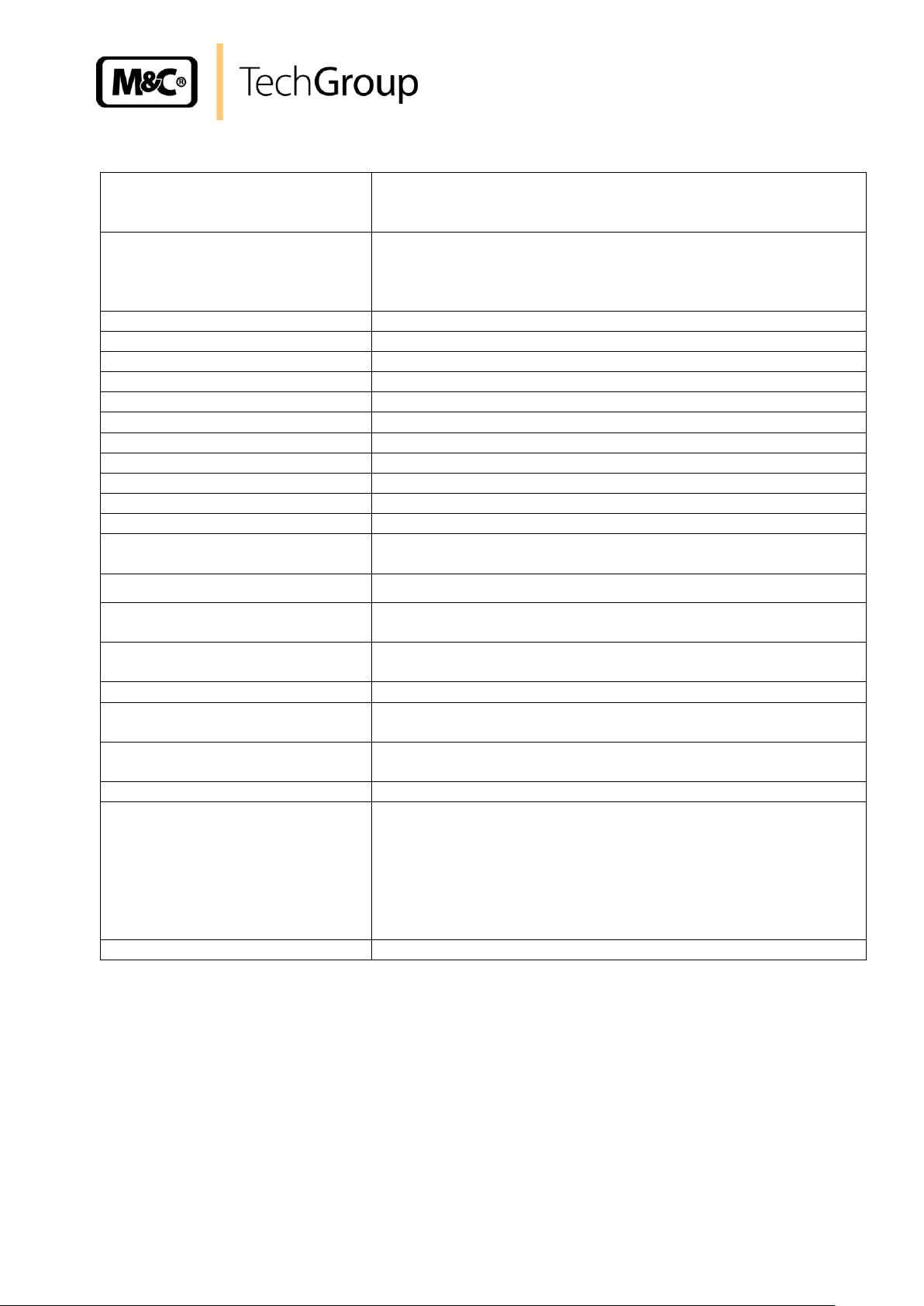
8
Part number
Type
Cooler - gas flow [l/h]
Power supply
03 G 1000
CSS 230V
ECP 1000 - 140l/h
230V 50/60Hz
03 G 1000a
CSS 115V
ECP 1000 - 140l/h
115V 60Hz
03 G 1100
CSS/C* 230V
ECP 1000 - 140l/h
230V 50/60Hz
03 G 1100a
CSS/C* 115V
ECP 1000 - 140l/h
115V 60Hz
03 G 2000
CSS-2 230V
ECP 2000 - 2 x 140l/h
230V 50/60Hz
03 G 2000a
CSS-2 115V
ECP 2000 - 2 x 140l/h
115V 60Hz
03 G 3000
CSS-3 230V
ECP 3000 - 350l/h
230V 50/60Hz
03 G 3000a
CSS-3 115V
ECP 3000 - 350l/h
115V 60Hz
03 G 3100
CSS-3/C* 230V
ECP 3000 - 350l/h
230V 50/60Hz
03 G 3100a
CSS-3/C* 115V
ECP 3000 - 350l/h
115V 60Hz
Options
03 G 9000
Extra charge for CSS... with integr. temp. controller 70304 f. heated sample line
03 G 9020(a)
Extra charge for CSS... with altogether 3 check valves
03 G 9025(a)
Extra charge for CSS... with altogether 4 check valves
03 G 9030(a)
Extra charge for CSS... with altogether 5 check valves
6 INTRODUCTION
This M&C unit provides completely pre-installed sample gas conditioning for continuous use and can
be excellently integrated within analysis systems. It is equipped with:
1 sample gas inlet;
Electric gas cooler;
Sample gas pump;
Condensation pump;
Micro fine filter with glass-fibre element (0,1µm);
External or manual switching for testing with zero or span gas by 3-way and 2-way
solenoid valves;
Status alarm with display for cooler temperature, flow alarm and liquid alarm;
2 sample gas outlets with flow meters incl. needle valve (70 l/h or rather 250 l/h);
PTFE hosing;
Optional: electronic temperature controller for heated sample lines.
Its compact construction means that it takes up little space. The CSS unit is ready for use within a
matter of a few minutes. This at last makes the usual time consuming procurement of individual components and assembly superfluous.
6.1 SERIAL NUMBER
The type plates bearing the serial number are located on the back panel of the 19“-rack-housing.
Always quote the device’s serial number when making inquiries and ordering spare parts.
6.2 POWER SUPPLY
Depending on the version, the CSS is operated with 115 or 230 V AC.
Precise details can be found on the device's type plate.
In dependence of the cooler type, the power supply and the version .../C -test gas to the probe- the
following types of the CSS can be distinguished:
* Version CSS.../C: test gas to sample probe
(a) : 115V-Version
Gas sampling and gas conditioning technology 4-1.1-ME
Page 9
7 TECHNICAL DATA
Gas flow rate**
CSS(/C) : max. 140l/h
CSS-2 : max. 2 x 140l/h
CSS-3(/C) : max. 350l/h
Flow meter
CSS(/C), CSS-2: 2 x with needle valve, adjustable to 70l/h,
flow meter FM1 with flow alarm sensor
CSS-3(/C) : 2 x with needle valve, adjustable to 250l/h,
flow meter FM1 with flow alarm sensor
Gas pressure
0,7bar to 1,4bar abs.
Sample inlet temperature**
max. 150°C
Sample inlet dew point**
max. 80°C
Sample outlet dew point
range of adjustment: +2 °C ..... +15 °C, factory setting: +5 °C
Dew point stability
at constant conditions < ± 0,1 °C
Gas filter F-0,1GF50
Glass fiber, retention rate 99,99% for particles > 0,1µm
Ambient temperature**
+5°C to +45°C
Storage temperature
-25°C to +65°C
Relative humidity
< 80%
Housing
19"-rack housing mounting 6 U, depth 350mm
Degree of protection
IP20, DIN40050
Weight
CSS(/C) : approx. 15kg
CSS-2, CSS-3(/C): approx. 16,5kg
Connections
G 1/4 i* - DIN ISO 228/1
Power supply
230V 50/60Hz or 115V 60Hz, CSS : 150VA
CSS-2/3: 250VA
Electrical connection
Power terminals max. 4 mm2 (4 x PG 13,5)
Alarm-/Control signal 15 pin Sub-D-Connector
Warm up time
approx. 10 min.
Material of sample contacting
parts
PVDF, glass, Viton, Novoprene, PTFE
Status signal for
Measure/Check, cooler temperature, liquid alarm, flow alarm:
potential free change over contact, max. 24V/1A
Test gas inlet - 2 x
solenoid valve actuated by manual or external switch
Option:
Electronic PID temperature controller for heated sample lines
front panel mounting
control range : 0°C to 200°C
sensor inlet : PT 100 and Fe-CuNi
controlling outlet : 10A solid state relay #
status alarm : integrated into the status signal
parameter : free adjustable
Electrical equipment standard
EN 60204-1 (DIN VDE 0113 Teil 1/02.86)
9
* other connections on request
** Maximum values in technical datas must be rated in consideration of total cooling capacity at 25 °C ambient temperature and an outlet dew
point of 5 °C.
#
standard for max. 20m heated sample line at 110W/m
Gas sampling and gas conditioning technology 4-1.1-ME
Page 10
10
Pumpe EinPumpe Aus
Sampling-Sy stem
Temp. controller
Nullgas
Zero gas
Meßgas
Sample gas
Messen
Measure
Pump off
Temp. Regler
CSS
Pump on
Prüfen
Check
Prüfgas
Test gas
Endgas
Span gas
LS/LA
Steuerung Intern
Extern-rt
Intern-gn
A-
A-
A±
Status
control intern
Ein
2
1
FA-1,bi
Sensor
Open
Auf
FPF-0,1
M&C
190,5
266
465
483
(1.4) 1 (1.2)
optional tempreature controller
(1.3)
1.2.1
1.2.4
1.2.5
1.2.3 1.2.2
1.2.6
A
A
(1.1)
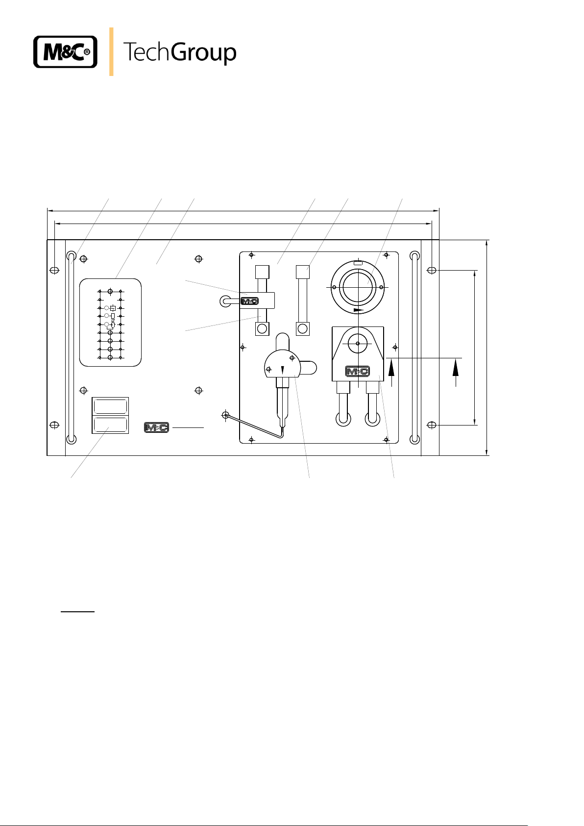
8 DESCRIPTION
The components of the M&C gas conditioning sampling system type CSS are mounted in a 19" rack
housing. The CSS may also be configured with an optional wall-mounting-bracket (Part-No.
03G9005).
Figure 1 Front view of the CSS
The front plate (1) displays the following components:
(1.1) operation and control board;
(1.2) flow components sub panel;
(1.3) option*- temperature controller for heated sample line (Part No. 03G9000);
(1.4) handles.
*
If the temperature controller option is not chosen a plastic plate will cover the opening.
Gas sampling and gas conditioning technology 4-1.1-ME
Page 11
11
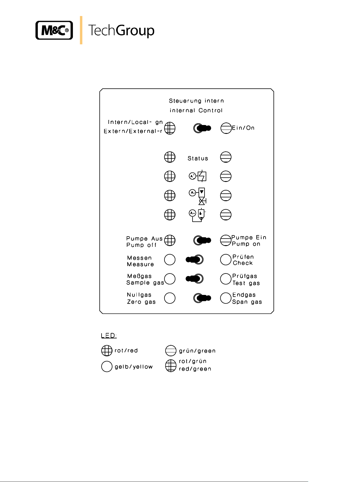
Figure 2 shows the operation and control board (1.1). The different functions are selected by toggle
switches and indicated with LED’s. The internal or external function is configured through the wiring in
the Sub-D-Plug (see 4.1) and indicated by a dual coloured LED on the operation and control board.
Figure 2 Operation and control board
Gas sampling and gas conditioning technology 4-1.1-ME
Page 12
12
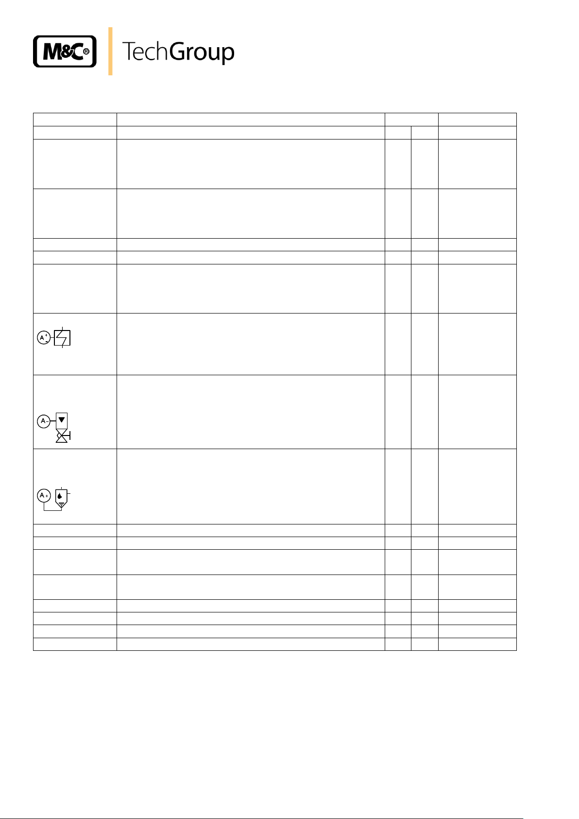
Function
Description
Switch
LED
l
r
Local Control
(intern)
control of the CSS with operation and control board;
link between pin 1 and 9 (connector X2, s. 10.2.2);
control power supply;
(dual col-
oured)
green
External Control
(extern)
external control with Sub-D-Plug X2 (s. 10.2.3),
switches of the operation and control board out of
function; control power supply after switching the CSS
on ;
(dual col-
oured)
red
On
internal control activated;
X green*
Off
switches CSS off
X no LED
Status
no alarm: CSS ready for operation;
alarm : cooler-/temperature-controller alarm;
flow alarm;
liquid alarm.
green*
red*
Cooler- Alarm
no alarm: CSS ready for operation;
alarm : CSS not ready for operation,
temperature of cooler <2°C or >8°C,
or optional temperature-controller:
controller not in range
green*
red*
FlowAlarm
no alarm: CSS in operation;
alarm : no gas flow (i.e. inlet or outlet
is blocked),
sample gas pump not in operation,
liquid alarm,
cooler-/temperature-controller alarm;
green*
red*
LiquidAlarm
no alarm: CSS ready for operation
alarm : condensate alarm;
green*
red*
Pump Off
sample gas pump off;
X red
Pump On
sample gas pump on;
X green*
Measure
CSS in sample mode,
signal contact available;
X yellow*
Check
CSS in test mode,
signal contact available;
X yellow*
Sample Gas
3-way solenoid valve open for sample mode;
X yellow*
Test Gas
3-way solenoid valve open for test mode;
X yellow*
Zero Gas
2-way solenoid valve open for Zero Gas;
X yellow*
Span Gas
2-way solenoid valve open for Span Gas;
X yellow*
The following chart describes the functions of the operation and control board.
* LED display also for external control
Gas sampling and gas conditioning technology 4-1.1-ME
Page 13
13
175
1.2.7 1.2.8
152
48
1.2.1 1.2.21.2.61.2.31.2.41.2.5
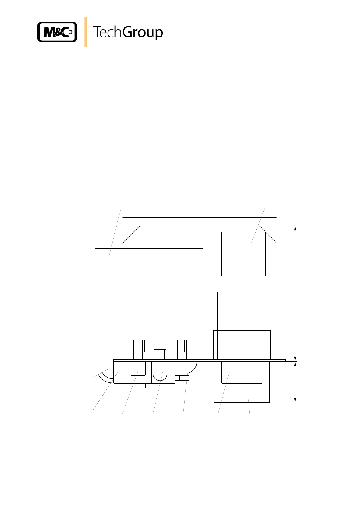
All of the maintenance components are mounted on the flow components sub panel (1.2) (s. Fig. 1
and 3) and are easily accessed by removing front panel mounting screws. These are:
(1.2.1) Gas-Filter FPF-0,1GF;
(1.2.2) Peristaltic pump SR25.1;
(1.2.3) Liquid-Alarm-Sensor LA1 with Flow-Chamber LS;
(1.2.4) Flow-Meter 1 FM40, measuring range 7-70l or 25-250l**
(1.2.5) Optical bi stable Flow-Alarm-Sensor FA-1,bi;
(1.2.6) Flow-Meter 2 FM40, measuring range 7-70l or 25-250l**;
(1.2.7) Gas Pump N3 KPE or N9 KPE**;
(1.2.8) Terminal X8
(** with version CSS-3... and CSS-3/C...)
Figure 3 Plan view of the components mounted on the Flow components sub panel
For maintenance it is possible to pull out the rack housing (1.2), without dismounting the complete
unit.
Gas sampling and gas conditioning technology 4-1.1-ME
Page 14

14
265
6
23
5
9
8
14
10 13
2120
Schnitt A-A
16
17
15 1924
1.2
Cooler
max. flow rate [l/h]
ECP 1000
140
ECP 2000
2 x 140
ECP 3000
350
NOTE!
The PSS must be stored in a weather-protected frost-free area ! Allows ade-
quate ventilation around the chassis !
Figure 4 Components mounted in the 19“ rack housing
The gas cooler (10) is fixed on the back panel of the 19“ rack housing. With respect to the maximum
flow rate required, the following versions are available:
Ambient air enters the chassis through the slots in the bottom (8) and top plate (9) of the 19“ rack
housing. This allows ventilation and cooling of the internal components including the gas cooler.
The cooler fan exhausts air out of the cut out in the side wall (6) of the 19“ rack housing.
The 3-way solenoid valve (14), for switching of the sample and test gas, is mounted in a special holder
(13) on the back panel (5).
Sectional view A-A in illustration 4 shows the two 2-way solenoid valves (16) and (17), for zero and
span gas. They are mounted with valve block (15) below the valve (14) on the back panel of the 19"
rack housing. Additional 3 span gas valves are possible as option (see page 8). The span gas valves
are preselected by snap switch 1.5 (Fig. 1).
The combined card for flow- and liquid alarm LFC-2 (20) is connected on the main circuit board (21).
The CSS is protected by fuse (F1= 2A, see wiring diagram in appendix).
Gas sampling and gas conditioning technology 4-1.1-ME
Page 15

15
10
7
435
258
X 1
Status X2
465
190,5
A
C G B
F
D
E I J
M
Power
connection
A1
L K H
N
All the electrical and tube-/hose connections are located on the back panel of the 19" rack housing.
These are:
(A) Sub-D-Plug X2 (see 10.2):
device status
- external status inquiry
measuring/test mode
internal ( the link between pin 1 and 9 is factory installed and
- control functions must exist for the local control to function)
external (with potential free contacts)
(A1) Reserve
(B) electrical junction box X1 (see 10.1):
- power supply
- option: connection heated sample line and temperature-sensor
(C)* sample gas inlet
(D) sample and test gas outlet 1 with Flow-Alarm
(E) sample and test gas outlet 2
(F) zero gas inlet
(G) span gas inlet
(H) condensate outlet
(I) test gas to the probe**
(J) ventilation**
(K) option: span gas 2 inlet, condensate outlet 2***
(L) option: span gas 3 inlet, sample gas outlet 3***
(M) sample gas inlet 2***
(N) option: span gas 4 inlet
Figure 5 Back-panel of the 19" rack housing
* (C) - (M) are PVDF G 1/4“ i fittings
** only version CSS.../C, test gas to probe
*** only version CSS-2
Gas sampling and gas conditioning technology 4-1.1-ME
Page 16

16
13
12
11
10
9
7
4
5 8 6
3 2 1
F G H
D
E
C
FM1
FM2
A
B
B2
FI1
M1
B1
E1
Y1
Y2
Y3
M1
CSS; CSS-3
Zero
gas
Span
gas
9
7
4
C
B1
E1
Y1
M K L
CSS-2
9 FUNCTION
The gas flow schematic of the CSS is shown in the following illustration.
Figure 6 Gas flow schematic
Principally, there are two main ways for gas to enter and flow through the CSS:
- sample gas flow (C, 4, 7, 9, 10, 12 and 13, D and E);
(version CSS-2 additional: M, 7, K);
- test gas flow (F or G, 5 or 6, 4, 7, 9, 10, 11, 12 and 13, D or E)
(Version CSS.../C: F or G, 5 or 6, I, 2, C, 4, ... see above).
The gas sample pump (10) transports the sample gas via the gas sample probe, consisting of a sample tube (1) and a filter (2), to the CSS. The heated sample line (3) is connected at the sample gas
inlet (C). In order to prevent early condensation of the sample gas, components (2) and (3) are
heated.
In the measuring mode, the 3-way solenoid valve (4) allows the flow to the gas cooler (7).
The dew point of the gas is maintained at a stable value of +5°C +/- 0,1 °C (for further specifications
see appendix).
Gas sampling and gas conditioning technology 4-1.1-ME
Page 17

17
The peristaltic pump (8) draws and removes the condensate via the condensation outlet (H) on back
panel.
The liquid alarm sensor (9) which located after the gas cooler protects the gas analysers in the event
of faulty gas drying. In the event of an alarm in the condensate removal, cooling or heating functions,
the 3-way solenoid valve is automatically closed. Also the measuring pump is switched off so that no
wet gases can reach the gas outlets (D) and (E). The alarm is shown on the operation and control
board of the CSS and is available on Sub-D-Plug X2 (A) as a status contact outlet (see 10.2.2 and
10.2.3).
After the sample gas pump (10) is a gas filter (11) for precipitation of the finest particles.
After the filter, the sample gas flows through both flow meters: the flow meters FM1 (12) and FM2 (13),
and the measuring outlets (D) and (E). Both flow meters are individually adjustable by a needle valve.
In order to keep the gas outlet dew point of 5°C, the total flow rate should not exceed the specified
maximum value (see 7.).
The minimum flow rate is determined by the sample gas pump (see 17.1). If the flow rate remains under the minimum value the pump membrane can be premature destroyed by over pressure.
The flow rate is controlled via needle valve on the flow meter FM1 and the optical bi stable flow sensor. The flow sensor can be moved on the flow meter glass and adjusted to an alarm value of your
choice. The flow is below the alarm value, this effects a flow alarm which is shown on the operation
and control board of the CSS and which is also available on Sub-D-Plug X2 (A) as a status contact
(see 10.2).
In the test mode, the 3-way solenoid valve (4) is switched to allow zero or span gas to enter the system. The inlets (F) and (G) are then available and the 2-way valves (5) or (6) open respectively.
Additional 3 span gas valves (K, L, N) are possible as option (see page 8). The span gas valves are
preselected by snap switch 1.5 (Fig. 1).
The versions CSS.../C are configured in such a way that the test gases first flow via the sample gas
probe and then via the sample gas inlet (C) to the gas cooler. Therefore, the CSS.../C is equipped with
the additional inlet fittings (I) and (J). The test gas outlet (I) is connected with the test gas inlet of the
sample gas probe.
In Version CSS-2 the gas cooler ECP2000 with two heat exchangers is mounted. Thus it is possible to
operate with a second independent sample gas flow. The sample gas line for the second independent
sample gas flow has to be connected to the inlet (M) and outlet (K) by customer. Condensate removal
happens via the condensate outlet (L). Sample gas pump, condensate pump, gas filter and alarm sensors have to be installed extern by customer.
In case of alarm, the 3-way solenoid valve opens automatically the gas way (4) - (J) and closes the
way (4) - (C). This guarantees that no sample gas or test gas can enter the system.
Zero and span gas both flow through the heat exchanger of the gas cooler. This configuration guarantees the same conditions during measuring and calibration.
The CSS gets its respective voltage via an electrical junction box X1 (B). Here, you can also find the
connections for the option "heated sample line with temperature controller" (specification see 10.1).
Gas sampling and gas conditioning technology 4-1.1-ME
Page 18

18
Electrical junction box X1
Power In 230V 50Hz, 150VA for CSS
Option controller 70304 for heated sample line
Power In 150V 60Hz, 1100VA for heated sample line
Power In 150V 60Hz, 1100VA for heated sample line
Connection for the temperature sensor of the heated sample line
PT100 / thermocouple +
PT100 / thermocouple -
PT100 (3-wire)
screening
10 ELECTRICAL CONNECTIONS
The electrical connections are located on the back panel of the 19“ rack housing (see fig.5)
10.1 ELECTRICAL JUNCTION BOX X1
Figure 7 shows the possible connections of the electrical junction box X1 (B).
For devices from 12/2001 to 01/2008 with controller 703: thermocouple + at terminal 11, thermocouple –
at terminal 12
Figure 7 Electrical junction box X1 (B)
The CSS is protected by fuse (F1= 2A, see wiring diagram in appendix). The fuse is located on the
main circuit board (see fig.4).
Gas sampling and gas conditioning technology 4-1.1-ME
Page 19

19
NOTE!
To guarantee the function of the CSS, the SUB-D-Plug must be mounted!
NOTE!
Breaking capacity : maximum 24V 1A!
10.2 SUB-D-PLUG X2
10.2.1 STATUS CONTACTS
Two potential free switches operating in ‘Safety-First’ function and guarantee an adequate signal for
CSS being in test mode, alarm mode or loosen voltage.
For one of the above mentioned situations the circuit is closed by the contacts MC (master contact, 5
and 15) ) and NC (normal closed, 7 and 14). In case that the CSS is ready for operation the contacts
MC and NO (normal open, 6 and 13) are switched.
Figure 8 Status contacts
The kind of alarm is displayed on the operation and control board (see fig.2).
Gas sampling and gas conditioning technology 4-1.1-ME
Page 20

20
NOTE!
For local control, the link between PIN 1 and 9 in the SUB-D-Plug is neces-
sary!
10.2.2 LOCAL CONTROL
For local control all functions of the CSS are effected by the operation and control board (functions
see 8.).
The way for gas to enter the CSS is chosen by operating the adequate switch on the operation and
control board (see 8.). All other possible gas ways will be automatically closed. This avoids measuring
inaccuracy by simultaneous feeding the CSS with different gases.
For version CSS.../C -test gas to sample gas probe (see 9.)- pin 1 and 4 in the Sub-D-Plug are
shorted-out.
Figure 9 Plan of terminal connections in the Sub-D-Plug X2 (A) for local control of the CSS... and CSS.../C
Gas sampling and gas conditioning technology 4-1.1-ME
Page 21

21
NOTE!
For external control, the link between PIN 1 and 9 in the D-SUB-Plug must
be removed!
Operating error by feeding the CSS simultaneous with sample- and test gas
must be excluded by customer!
10.2.3 EXTERNAL CONTROL
The external control off the CSS has to be realised by customer by means of potential free switches.
The selector switch functions of the control board (s. 8.) are out of operation.
Figure 10 Plan of terminal connections in the D-Sub-Plug X2 (A) for external control of the CSS... and
CSS.../C
For version CSS.../C -test gas to sample gas probe a link between pin 1 and 4 in the D-Sub-Plug is
mounted.
Gas sampling and gas conditioning technology 4-1.1-ME
Page 22

22
Terminal
Path
Connections
Terminal
Path
Connections
d2
power 230/115V
L
d32
alarm contact 2
NC
z2
power 230/115V
N
d12
FA sensor
brown
z4
power 230/115V
PE
d16
FA sensor
green
d4
supply
+15V up to +24V DC
d14
FA sensor
white
z4
supply
0V DC
z16
FA sensor
yellow
d8
LA sensor
shielding
z22
alarm contact 1
MC
z8
LA sensor
white
d22
alarm contact 1
NO
z28
alarm contact 1
MC
z24
alarm contact 1
NC
d28
alarm contact 1
NO
d24
alarm contact 2
MC
z30
alarm contact 1
NC
z26
alarm contact 2
NO
d30
alarm contact 2
MC
d26
alarm contact 2
NC
z32
alarm contact 2
NO
+
+
+
LM1830
IC2
5
10
11
+
9
47nF
12
1
7
14
+
3,9nF
gn
rtgnrt
gn
K1
K1
100nF
100nF
B5-bi
mono=offen
bi=geschlossen
B4+B5
B4-bi
open at mono
120-200mV
120-200mV
1µF
+
+
22µF
&
1412
7
3
4
&
65IC3 4093
br=brown/braun
gn=green/grün
rt=red/rot
ws=white/weiß
ge=yellow/gelb
V2-V5 Transistoren BC 239C
D3;D8-D12;D14 Dioden 1N4148
Relais K1;K2 max. 250V DC/AC 90W,250VA,1A
LFC-2 01E1385 T1=3,5VA Frontplatte 6TE
LFC-2CSS 03E2026 T1=7VA ohne Frontplatte
P5 = switch-off-hysterysis 3-13 sec.
P5 = Alarmfreigabeverzögerung 3-13 sek.
P6 = Alarmfreigabeverzögerung 3-13 sek.
P6 = switch-off-hysterysis 3-13 sec.
10-100k
K2
K2
X1
(DC +15V-24V)
d2
B2 115V
B1 230V
B3 115V
d4
z2
L 230V/115V
N 230V/115V
z4
(PE/DC 0V)
LA-Sensor
d8
LA-Sensor ws
z8
LA 1MC
z28
LA 1NO
d28
LA 1NC
z30
LA 2NC
LA 2NO
LA 2MC
d32
z32
d30
d12
FA-Sensor gn
d16
FA-Sensor ge
z16
FA-Sensor ws
d14
FA 2MC
FA 2NO
FA 2NC
d24
z26
d26
FA 1NC
FA 1MC
FA 1NO
z24
z22
d22
Steckerleiste DIN 41612 F-d/z
2x115V/2x15 3,5VA
T1
1N4007
D1
1N4007
D2
230V
B1 geschlossen/close
B2;B3 offen/open
115V
B2;B3 geschlossen/close
B1 offen/open
FA-Sensor br
470µF
C1
35V
IC1
7812
1µFC235VC335V
47µF
C4
35VC535V
D5
R2
470
D3
K1
D6
D7
ZPD 5,6
D41kR3
3k3
R24
BC239C
V1
D16
D15
3k3
R21
1k
R22
K2
D14
R1
39k
V4
V5
R17
47k
R18
220k
R19
47k
R20
220k
C8
35V
C9
16V
D13
ZPD9.1
R23
470k
R16
100k
R15
100k
P6
1M
P5
1M
R14
10k
R12
15k
R10
10k
P2
200k
R13
1k5
R11
56k
D9
D10
D11
D12
R8
10kR615k
C7
35V
C6
35V
V3
V2
R9
56kR756k
D8
P1
200kR5330
10.3 LIQUID- AND FLOW ALARM CARD LFC-2
The LFC-2 is a combined electronic card operating the flow alarm sensor FA1bi and the liquid alarm
sensor LA1.
Pulsating gas flow can release a unintentional flow alarm. To avoid this the LFC-2 is equipped with
slow operation -time lag to eliminate the alarm- and slow release -alarm with time lag. Times in between 3 and 13 seconds (3 seconds are factory-aligned) are continuously adjustable by the potentiometers P5 and P6 (see Fig. 11, wiring diagram LFC-2). For more specific information about the liquid
alarm sensor LA1 and the flow alarm sensor FA1bi please see the data sheets 5-6.10.1 and 5-5.1.1.
The plan of terminal connections is displayed in the following chart.
Gas sampling and gas conditioning technology 4-1.1-ME
Page 23

23
From Version 03.2000
Figure 11 Circuit diagram LFC-2
Gas sampling and gas conditioning technology 4-1.1-ME
Page 24

24
(1)
Actual value display
red, 10mm high, 4 digits
(4)
PGM-key in order to select parameters
in order to change values
in order to change values
Exit-key in order to leave the levels
(2)
Active Setpoint
Factory setting SP1
(5)
Indication
yellow for
- Switch status of binaryoutputs 1 – 6
(display lights up = on)
- ramp/programm function is active
- manual operation is active
(3)
Setpoint
Four digit, green; decimal place is configurable;
Also used for operator prompting (display of
parameter and level symbols)
(6)
16-segment display for the unit °C / °F
factory setting °C
11 DESCRIPTION OF THE OPTIONAL TEMPERATURE CONTROLLER 70304 FOR
HEATED SAMPLE LINES
Figure 12 Display/control elements
12 OPERATING PRINCIPLE OF THE CONTROLLER 70304
Operating and programming of the controller takes place on two levels. On the first level for normal
operation, alarms can be resetted or in case of startup a control circuit, self-optimising is activated.
Underneath there is the user level. All important adjustments of the controller are combined on the
user level and can be changed after removing the level inhibit.
12.1 PARAMETER OF THE USER LEVEL WITH FACTORY SETTING
Setpoint SP, factory setting = 180°C
Max. low temperature difference to the setpoint Lo-t, factory setting = 10°C. In case of falling
Gas sampling and gas conditioning technology 4-1.1-ME
below, an alarm signal takes place
Page 25

25
W AR NIN G!
Observe the maximum temperature of the device to be controlled
to avoid damaging the same.
Function of the controller Fnct, factory setting = 0 : fixed-setpoint controller. Other values are
not adequate for the operation of M&C products.
Sensor type SenS, factory setting = 2: Resistance thermometer in 2-wire circuit
1: Resistance thermometer in 3-wire circuit
2: Resistance thermometer in 2-wire circuit
4: Thermocouple
Linearization Lin, factory setting = 1, Pt100
1: Pt100
9: Fe-CuNi J
11: Fe-CuNi L
12: NiCr-Ni K
Further information is in the separate manual 2-5.1.1ME of the controller 70304. The manual is available for download on the M&C-website www.mc-techgroup.com.
13 CHANGE OF PARAMETERS
To change parameters the level inhibit on the user level has to be removed.
13.1 REMOVING AND ACTIVATING THE LEVEL INHIBIT
To remove the level inhibit, act as follows:
Standard display (below setpoint, up actual value ) has to be visible
Press key PGM and simultaneously for 5sec.,
display = Code 3 (all levels are locked)
Press PGM
Change value from 3 to 2 with key
The value is blinking after 2sec. and the change is taken over
The user level is unlocked now
Press EXIT
To activate the level inhibit, act as follows:
Standard display (below setpoint, up actual value ) has to be visible
Press key PGM and simultaneously for 5sec.,
display = Code 2 (all levels are locked)
Press PGM
Change value from 2 to 3 with key
The value is blinking after 2sec. and the change is taken over
The user level is locked now
Press EXIT
Gas sampling and gas conditioning technology 4-1.1-ME
Page 26

13.2 MENUE STRUCTURE
Lin
Exit
Time out >2 min
290 .0
300 .0
PGM
User
SP
ALSE
Lo-t
PGM
LFun
Fnct
rASL
SenS
PGM
Standard display
PGM
PGM
PGM
PGM
PGM
PGM
PGM
Exit
Changing parameters with or
Takeover of changed values after 2 sec.
Exit
SP = Setpoint
(ALSE = Excess temperature with
lock)
Lo-t = Low temperature alarm
(LFun = Limit comparator function)
Fnct = Function of controller
(rASL = Ramp slope)
SenS = Sensor type
Lin = Linearization
Parameter in brackets do not apply!
Generally:
Changing to the user level with PGM-key (display = User)
To choose the first parameter press PGM-key again (display = SP)
Changing to the next parameter with -key
Back to the standard display press EXIT-key (2x)
Figure 13 Menue structure
13.3 TIME OUT
If no operation takes place, the controller automatically returns to the standard display after about 2
minutes using any changed parameters.
Gas sampling and gas conditioning technology 4-1.1-ME
26
Page 27

27
NOTE!
The CSS must be stored in a weather-protected frost-free area!
NOTE!
The equipment is to be used in a vertical position only. The perfect
functioning of the seperation and drainage procedures will only be
guaranteed if the equipment is used in a vertical position.
The gas conditioning system should be installed in an area well away
from any heat emitting sources in order to prevent demage caused by
an accumulation of heat.
Pay attention to a non critical installation for individuals.
The compact gas conditioning system is preferably designed for
mounting in a cabinet. When the cabinet is installed outside, ample protection against the effects of direct sunlight and dampness must be
provided. In winter, the equipment must only be used in frost-free areas; pay attention to the protection class of the device.
In order to guarantee the operational safety of the gas conditioning system and the additionally connected analysers, and to avoid false
alarms, the gas conditioning system should not be used at temperatures other than those specified.
It is of great importance that the analysers which have been additionally connected be used at temperatures well above the specified gas
outlet dew point of +5°C. This prevents the gas in the connector lines
from condensing completely.
In the event of the unheated sample gas lines being connected to the
gas conditioning system on a slope, it is not necessary to carry out a
preliminary condensate removal.
14 RECEIPT OF GOODS AND STORAGE
The CSS is completely pre-installed and normally delivered in one packaging unit.
Please take the gas conditioning system and possible special accessories carefully out of the pack-
aging material immediately after arrival, and compare the goods with the items listed on the delivery
note;
Check the goods for any damage caused during delivery and, if necessary, notify your transport
insurance company without delay of any damage discovered.
15 INSTALLATION INSTRUCTIONS
The compact construction of the CSS means that it takes up little space and that the 19“ unit can be
excellently integrated within analysis systems.
Gas sampling and gas conditioning technology 4-1.1-ME
Page 28

28
NOTE!
The CSS is equipped with G1/4“i connections.
Do not mix up the hose connections: they are clearly marked. After all the hoses have been connected, the tightness of such leads
should be checked.
NOTE!
The tightness of the connections can only be guaranteed if the
connecting hose has a straight rim (hose cutter).
W AR NIN G!
Aggressive condensate is possible. Wear protective glasses and
proper protective clothing!
W AR NIN G!
False supply voltage can demage the equipment. When connecting the equipment, please ensure that the supply voltage is identical with the information provided on the model type plate!
16 SUPPLY CONNECTIONS
16.1 HOSE CONNECTION
Connection hoses with dimensions DN 4/6mm are utilised for all models.
The following lines have to be connected (Fig. 5):
sample gas line to connection (C) respectively to connection (M), operating with version CSS-2
(second independent gas flow);
zero gas line to connection (F);
span gas line to connection (G);
line -test gas to sample gas probe (CSS.../C)- to connection (I);
analyser(s) to outlets (D) and (E); maximum two sample gas outlets are available; with version
CSS-2 an additional sample gas outlet (K) is available;
connect the condensate hose to the outlet (H) respectively to the outlet (L), operating with version
CSS-2 ( second independent gas flow); the hose must be laid with slope to a ventilated sewer or
reservoir; it is absolutely necessary to install the ventilation outside the analysers cabinet and analysers house;
16.2 ELECTRICAL CONNECTIONS
Gas sampling and gas conditioning technology 4-1.1-ME
Page 29

29
NOTE!
For the erection of power installations with rated voltages up to 1000V, the
requirements of VDE 0100 and relevant standards and specifications must
be observed!
The main circuit must be equipped with a fuse corresponding to the nominal current (over current protection); for electrical details see technical
data.
Connect power supply (optional heated sample line with temperature sensor) to the correspond-
ing terminals of the electrical junction box X1 (Fig.7); intend for a main switch and a corresponding fuse protection; the dual coloured LED for local control shines green if the CSS is alive.
17 STARTING
Before starting the gas conditioning system please pay attention to the site-oriented and processoriented precautions.
The following description is valid for starting the device at ambient temperatures > +8°C.
The following steps should be carried out before initial start-up:
The function of the CSS is only guaranteed when the sub-D-plug X2 is mounted;
For internal control of the CSS a bridge between contact 1 and 9 in the sub-D-plug is necessary;
For external control of the CSS operating errors caused by feeding test- and sample gas simultaneous
have to be prevented by customer.
17.1 MEASURE
Turn switch to ‘On’ (see fig.2, LED green); for external control the dual coloured LED shines red;
Switching the CSS into operation displays the following alarms:
Cooler alarm (LED red):
after the cooler is ready for operation (cooler temperature >2°C and <8°C) the alarm is eliminated
(LED green). The 3-way solenoid (4) (see fig.6) opens automatically for sample gas and the sample
gas pump (10) (see fig.6) is ready for operation.
Flow alarm (LED red):
up to now there is no gas flow. Even when the ball of the flow meter passes the alarm value the alarm
is eliminated (LED green).
Turn switch to ‘Measure’ (LED yellow); available as contact outlet (see Fig.9);
If the cooler alarm is eliminated:
turn switch to ‘Pump on’ (LED green);
adjust flow meter with needle valve to the demanded value;
Gas sampling and gas conditioning technology 4-1.1-ME
Page 30

30
NOTE!
Adjust the flow meter FM1 to a flow rate above the demanded alarm value.
Because of breaking the outlet dew point (5°C) the total flow rate should not
pass the specified maximum value (see 2.).
The minimum flow rate is determined by the sample gas pump. This requires the following minimum values:
N3 KPE: approx. 60l/h;
N9 KPE: approx. 200l/h;
If the flow rate remains under the minimum value the pump membrane can
be premature destroyed by over pressure !
17.2 CHECK/CALIBRATION
turn switch to ‘Check’ (LED yellow); is available as contact outlet;
turn switch to ‘Test gas’ (LED yellow);
turn switch to ‘Zero gas’ (LED yellow);
After this calibration or checking the measuring range with zero gas can happen.
turn switch to ‘Span gas’ (LED yellow);
Now calibration or checking the measuring range with span gas can be started.
For returning to the measuring mode:
turn switch to ‘Sample gas’ (LED yellow);
If the analyser has reached the measuring range:
turn switch to ‘Measure’ (LED yellow).
Gas sampling and gas conditioning technology 4-1.1-ME
Page 31

31
NOTE!
For self-optimising of the control circuit, the heating of the heated
sample line must be connected to the appropriate terminals of the
CSS (s. 10.1).
W ARNIN G!
Before connecting the heated sample line, isolate the unit from
the supply!
NOTE!
Before stopping the CSS, sample gas should be expelled with
inert gas (Nitrogen or air).
The area in which the equipment is situated when not in use must
be kept free of frost at all times.
17.3 SELF-OPTIMISING (PID-FUNCTION) OF THE CONTROLLED SYSTEM
The controller type 70304 has the possibility of a self-optimisation-function if it operates as a PIDcontroller. In all M&C components this function is pre-adjusted. This means that a self-optimisation is
necessary starting up the component.
The self-optimising function can be activated as follows:
After cable connection (Figure 7), switch on the supply.
When the actual value (top display, red indicator)
reaches the setpoint value (bottom display, green indicator), press + keys simultaneously
for longer than 2 seconds. The word ”tUnE” now flashes in the setpoint value display and the
self-optimising function is activated.
Self-optimization has finished when the display changes to the standard display. The time of
self-optimizing depends on the control circuit.
To cancel the self-optimization press the keys + simultaneously.
The heated sample line now works in optimized operation.
18 CLOSING DOWN
For stopping the CSS carry out the following steps:
turn switch to ‘Pump off’ (LED red ); is not displayed on the control board in case of external control.
switch the CSS off; for local control turn the switch ‘On’ left (LED extinguishes)
Gas sampling and gas conditioning technology 4-1.1-ME
Page 32

32
W ARNIN G!
Dangerous voltage. It is necessary to take the equipment off the
mains before any assembly, maintenance or repair work is carried
out.
In order to do this the mains plug has to be removed from the
mains plug socket!
NOTE!
In order to protect the analysers which have been additionally
connected, it is recommended that in the event of a condensation
irruption the moist filter elements be replaced.
19 MAINTENANCE
Before the maintenance work is carried out, it is necessary that the specific safety procedures pertaining to the system and operational process be observed!
The frequency of the maintenance work depends on the operational process and can therefore only be
determined in each individual case. Maintenance instructions pertaining to individual components can
be found in the instruction manual for individual components.
All parts which require maintenance work are housed in the gas conditioning system in such a way so
that they are easily accessible. These are:
The filter element of the preliminary filter FPF-0,1GF.
The preliminary filter for the peristaltic pump PF2. If the condensate contains particle residue, the
preliminary filter should be replaced at regular intervals. The ‘one-way’ filter is situated in the suction side of the pump hose and can be easily replaced;
Hoses of the Condensate pump SR25.1. These should be checked every six months and, if neces-
sary, replaced;
Diaphragm of the sample gas pump N3KPE or N9KPE.. These should be checked every six
months and, if necessary, replaced;
20 DISMOUNTING THE FLOW COMPONENTS SUB PANEL
The dismounting of the flow components sub panel is carried out stepwise as follows:
check if the CSS is disconnected from all power supplies;
loosen the fastening screw from the flow alarm sensor;
remove the sensor from the flow meter glass;
turn the union nut of the liquid alarm sensor left by hand (fix the sensor while loosen the nut);
pull out the sensor of the flow chamber;
unscrew the hose connections of the condensate pump;
Gas sampling and gas conditioning technology 4-1.1-ME
Page 33

33
W ARNIN G!
Aggressive condensate is possible. Wear protective glasses and
proper protective clothing!
NOTE!
The flow components sub panel is not rail mounted!
release the fastening screws from the flow components sub panel;
pull out half the sub panel and lower so that the backside tube connections are accessible;
release the tube connections at the top of the flow meters FM1 and FM2;
disconnect the tube ‘flow chamber/heat exchanger’ on the side of the chamber;
pull out the hoses of the condensate pump through the guides in the sub panel;
pull out the plug in connection from the connector block X8 (see fig.3).
Now the sub panel can be completely taken out of the 19“ housing.
Mounting the sub panel happens in opposite order. Please pay attention to the following instructions:
mounting the plug in connection look out for the sequence of numbers;
after the implementation of the condensate hoses pay attention of possible folds;
tighten the union nut of the liquid alarm sensor by hand;
position the flow alarm sensor and tighten the fastening screw by hand.
21 ALARMS AND ELIMINATION
The alarms are displayed on the operation and control board (see fig.2) by LED’s. The alarms are
available as a status contact in the Sub-D-Plug (s. 10.2.2 u. 10.2.3).
21.1 VOLTAGE LOSS
At a voltage loss the operation and control board of the CSS is out of function and the LED’s are extinguished (see 8.). A signal is available at the alarm status contact in the Sub-D-Plug (s. 10.2.1).
Carry out the following controlling steps:
check the position of the main switch;
check the external fuse; if necessary exchange the fuse;
check the fine fuse (F1=2A, see circuit diagram in the appendix) on the main board of the CSS; if
necessary exchange the fuse.
Gas sampling and gas conditioning technology 4-1.1-ME
Page 34

34
21.2 COOLER ALARM/TEMPERATURE CONTROLLER ALARM
Cooler alarm is released if the cooler temperature is <2°C or >8°C, also
in the period till the CSS is ready for operation. As well cooler alarm is
released if the temperature controller (option) of the heated sample line
is out of range. The operative cooler/temperature controller opens the 3way solenoid valve and makes the function ‘Pump On’ possible.
For alarm elimination please check:
the function of the cooler; see separate manual 3-1.1-MD;
ambient temperature > 2°C ?
the function of the temperature controller; see separate manual 2-5.1.2-MD.
21.3 FLOW ALARM
The gas flow is adjusted by the flow meter FM1 and observed by an optical bi stable flow alarm sensor. The sensor can be moved on the flow
meter glass and adjusted to any alarm value. The sensor recognises the
variation in direction of the ball in the flow meter. If the ball passes the
alarm limit in the direction of increasing flow rates the alarm is eliminated. In opposite direction alarm is released.
Possible reasons for flow alarm are:
period till the CSS is ready for operation;
sample gas pump is out of order;
the flow rate is adjusted below the alarm limit;
cooler alarm/temperature controller alarm; the 3-way solenoid valve is automatically closed and the
sample gas pump is switched out of order;
liquid alarm; the 3-way solenoid valve is automatically closed and the sample gas pump is switched
out of order;
the tubes are blocked so gas flow isn’t possible;
The following steps are possible to eliminate the flow alarm:
check if the adjusted flow rate is above the alarm limit;
check if the sample pump is switched on (see fig.2, LED green);
check if there is no other alarm; correction see 21.2 and 21.4
check if the gas can passes the gas tubes.
If the alarm can not be eliminated in spite of the above mentioned steps the electronic card LFC-2 has
to be checked.
Gas sampling and gas conditioning technology 4-1.1-ME
Page 35

35
21.4 LIQUID ALARM
The M&C liquid sensor alarm unit LA1 is useful whenever liquid can
damage a gas analyser system. This may occur if a gas dryer unit or a
drain system fails.
The M&C LA1 liquid sensor is constructed in the following way that any
droplets of liquid in the sample gas are attracted under gravity to the
sensor surface and even the smallest liquid droplets trigger a sure and
rapid alarm.
In the event of an alarm the liquid alarm sensor switches the sample gas
pump off and closes the 3-way solenoid valve for sample gas.
To eliminate the alarm carry out the following steps:
switch the CSS off;
disconnect the line to the analyser;
open the sample gas inlet;
check the hoses of the condensate pump SR25.1; if they are defective change hoses;
switch power supply on and check the condensate pump if it works;
let the condensate pump work, until no more condensate is conveyed;
dismount the LA sensor;
dry the sensor;
remove the filter element from the gas filter FPF-0,1GF;
before starting the CSS with sample gas the gas ways must be dry. For this the CSS must be
sweeping about 1 hour with ambient air. The filter element remains dismounted and the sample gas
inlet and outlets remain open, disconnected from the system.
install dry or new filter element.
If the elimination of the alarm is not possible in spite of the above mentioned steps you should check
the following components:
gas cooler;
electronic card LFC-2.
Gas sampling and gas conditioning technology 4-1.1-ME
Page 36

36
19“ GAS CONDITIONING UNIT TYPE CSS...
(C) consumable parts, (R) recommended spare parts, (S) spare parts
recommended quantity
in operation [years]
Artikel-Nr.
Bezeichnung
C/R/S
1 2 3
Cooler ECP-1000/ECP-2000, ECP-3000: 10 (s. Fig.4)
93 K 1030
Jet-Stream heat exchanger ECP-1000/2000G 90°
R 0 1
1
93 K 0150
Jet-Stream heat exchanger ECP-3000G 90°
R 0 1
1
90 K 0115
Thermal conductivity paste, 50g
R 1 1
2
93 K 0020
Power supply board compl. for ECP1000-3000
R - 1
1
93 K 0530
ECP-1000 Netzteilplatine kompl.
R - -
1
93 K 0030
Fine fuse 0,8AT 5x20 ECP-1000
R 2 4
4
93 K 0540
Fuse 5 X 20, 1,6 AT for ECP-2000/3000
R 2 4
4
93 K 0010
ECP-1000 fan 12V DC
C - -
1
93 K 0036
Diode ECP-1000
R - -
1
90 K 2010
Rectifier for cooler type ECP1000-3000
R - -
1
90 K 2020
Power transistor BUZ11 for ECP1000-3000
R - -
1
93 K 0040
PT-100 temperature sensor
R - -
1
93 K 0045
ECP-1000 peltier element 4/4
R - -
1
93 K 0520
ECP-2000/3000 peltier element 6/6
R - -
1
90 K 0145
ECP-alarm relay DSP1
R - -
1
Peristaltic pump SR25: 1.2.2 (s. Fig.3)
90 P 1007
SR25 pump hose with PVDF tube connectors DN
4/6mm
C 1 2
4
90 P 1020
Driver complete for peristaltic pump SR25.1
S - 1
1
90 P 1010
Set contact spring for SR25.1 (4 pcs.)
R 1 2
2
90 P 1045
Contact pulley(1 pc.) for (2 pcs./pump required)
S 2 4
4
90 P 1050
Conveying belt for SR25
S - 1
2
90 P 1025
S-bolt S - - 1
01 P 1000
Peristaltic pump complete, 230/115V 50/60Hz
R - -
1
3-Way solenoid valve: 14 (s. Fig.4)
90 K 6040
3-Way solenoid valve, 230V f. CSS(/C)/CSS-3(/C)
S - -
1
90 K 6041
3-Way solenoid valve, 115V f. CSS(/C)/CSS-3(/C)
S - -
1
2-Way solenoid valve: 16 (s. Fig.4)
90 G 3000
2/2-way solenoid valve 6011 for CSS 230V 50Hz
for CSS(/C) and CSS-3(/C)
S - -
1
90 G 3005
2/2-way solenoid valve 6011 for CSS, 115V
for CSS(/C) and CSS-3(/C)
S - -
1
Universal filter FPF-0,1: 1.2.1 (s. Fig.3)
90 F 0009
Filter element type F-0,1GF50 0,1µm
R 4 8
12
90 F 0118
Filter glass F-45
R 1 2
2
90 F 0044
Viton-O-ring, 35 for FPF-0,1
R 1 2
2
90 F 0095
PVDF filter ement clamp FPF-GF
S - 1
1
22 SPARE PART LISTS
Wear, tear and replacement part requirements depend on specific operating conditions.
The recommended quantities are based on experience and are not binding.
Gas sampling and gas conditioning technology 4-1.1-ME
Page 37

37
19“ GAS CONDITIONING UNIT TYPE CSS...
(C) consumable parts, (R) recommended spare parts, (S) spare parts
recommended quantity
in operation [years]
C/R/S
1 2 3
Flowmeter FM40: 1.2.4 (s. Abb.3)
90 A 0015
Flow meter glass for FM40 range 7-70 l/h air
for version CSS... and CSS.../C
S - 1
1
94 F 0015
Flow meter glass for FM40 range 25-250 l/h
air for version CSS... and CSS.../C
S - 1
1
90 A 0018
Viton O-ring 9 für flow meter glass
R 2 4
6
09 F 4000
Flow meter FM40 7-70l/h (compl.),
for versions CSS... und CSS.../C
S - -
1
09 F 4010
Flow meter FM40 25-250l/h (compl.),
for versions CSS... und CSS.../C
S - -
1
Liquid sensor LA1S: 1.2.3 (s. Abb.3)
90 E 1000
O-ring, Viton - 14, LA1
R 1 2
3
90 E 1010
Ring, PVDF - 16, LA1
R 1 2
3
Fine-wire fuse CSS:
90 G 3010
Fuse 5 X 20mm, 2 AT for CSS
R 2 4
4
Internal tubing:
05 V 6600
Ferrule 4/6 PV
R
10
15
15
05 V 6605
Union nut M10-4/6 PV
R
10
15
15
02 B 1000
PTFE- tube NW 4/6, quantity per meter
S 2 4
6
10 T 1000
Hose cutter
S 1 1
1
Diaphragm pump type N3 KPE/KP18; N5 KPE/KP18
90 P 2100
Square cap type D3 for N3-N5 KPE, PVDF,
1/8"i
S - -
1
90 P 2120
Membrane type S3, Viton/PTFE for N3N5KPE
C 1 2
3
90 P 2115
O-Ring type O3, for N3-N5 KPE, 1pc., Viton,
(2 pcs./pump)
C 2 4
6
90 P 2110
Valve reed type V3, for N3-N5 KPE, 1 pc,
material: Viton
C 2 4
6
90 P 2105
Spacer type Z3, for N3-N5 KPE, material:
PVDF
S - -
1
Diaphragm pump type N9 KPE/KP18
90 P 2200
Square cap type D9 for N9 KPE, PVDF, 1/8"i
S - -
1
90 P 2220
Diaphragm type S9, for N9 KPE, material:
Viton/PTFE
C 1 2
3
90 P 2211
Valve plate with seal for N9 KPE, 1 pc., material: Viton. (2 pcs./pump)
C 2 4
6
90 P 2205
Spacer type Z9, for N9 KPE, material: PVDF
S - -
1
Gas sampling and gas conditioning technology 4-1.1-ME
Page 38

38
23 APPENDIX
Pin assignment for external drive of the CSS
Circuit diagram gas conditioning CSS,
drawing number : 2443-5.01.5;
CSS wit 4 x span solenoid valves,
drawing number : 2443-5.03.0;
For further product documentation, please see our internet catalogue:
www.mc-techgroup.com
Instruction manual electric gas cooler ECP 1000/2000/3000,
document : 3.1.1-ME
Instruction manual peristaltic pump SR25.1, SR25.1-G,
document : 3-7.1-ME
Instruction manual diaphragm pump series N
document : 6-1.2.1-ME
Instruction manual Universal-Filter FPF-0,1,
document : 5-0.1-ME
Flowmeter FM 40,
document : 5-6.1.10
Optical bi-stable flow alarm sensor FA-1, bi,
document : 5-6.10.1
Liquid alarm sensor LA1...,
document : 5-5.1.1
Temperature controller 70304,
document : 2-5.1.3-ME
Gas sampling and gas conditioning technology 4-1.1-ME
Page 39

39
12345678910111213
25 24 23 22 21 20 19 18 17 16 15 14
Endgas 4 EIN
Span gas 4 ON
Span gas 2 ON
Endgas 2 EIN
Span gas 1 ON
Endgas 1 EIN
Span gas 3 ON
Endgas 3 EIN
Prüfen NO
Check NC
Prüfen NC
Check NO
Status MC
Status MC
Status-Kontaktausgänge
Status-contacts
Schaltleistung 24V 1A
contact rating 24V 1A
Check MC
Prüfen MC
Status NC
Status NC
Meßgas EIN
Zero gas ON
Nullgas EIN
Sample ON
Prüfgas über Sonde nur bei Option CSS-C
Cal. gas to the probe only by option CSS-C
+15V
+15V
Pump ON
Pumpe EIN
Steuerung extern
Controll extern
Status NO
Status NO
CSS Ansteuerung von Extern
CSS controlling external
Achtung! Bei Steuerung intern ist die Brücke
1-14 im Dsub-Stecker unbedingt erforderlich. *
pin1 and 14 in the Dsub-plug is necessary. *
Attention! For function intern the link between
*
intern extern
Figure 14 Pin assignment for external drive of the CSS
Gas sampling and gas conditioning technology 4-1.1-ME
Page 40

40
Figure 15 Circuit diagram gas conditioning CSS
Gas sampling and gas conditioning technology 4-1.1-ME
Page 41

41
Figure 16 CSS with 4 x span solenoid valves
Gas sampling and gas conditioning technology 4-1.1-ME
 Loading...