

Page 1
Manual CLF-5, CLF-5/W
Application
The M&C fluid particle filter CLF-5 , CLF-5/W is suitable for filtration of fluid
particles of all types and is recommended for sample gases with an acid
dew point above 100°C. Examples are measurements in flue gas of heavy
oil and black coal combustions.
The filter separates the aerosols (very fine fluid particles) which still pass
the gas cooler. The most effective position of the CLF-.. filter is downstream
the sample conditioning close to the flow meter of the analyser. For
additional system protection we provide the version CLF-5/W with
integrated hydrophobic diaphragm, working as a liquid stop.
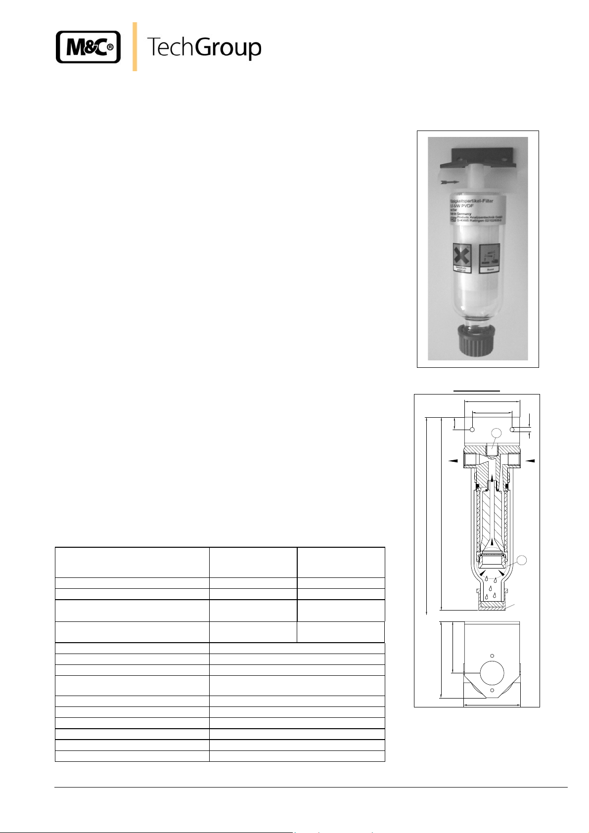
Description
The filter element of the M&C fluid particle filter is constructed in two
sections with a flow direction from the inside to the outside of the filter
element. The inner, very fine, fibre layer binds the fluid particles suspended
in the gas and leads them together with the gas flow to the outer, larger
layer. On their way through the filter element, the very fine fluid particles
accumulate with others and form droplets. The vertical flow direction and
the force of gravity cause the droplets to drip into the filter pot.
The filter element remains fully effective even when completely saturated
with fluid. If it is not effected by solid particles the lifetime is nearly
unlimited. The compressed Micro-Fibres are made with binding of PVDF in
order to prevent influences on the sample gas.
The version CLF-5/W is equipped with an integrated liquid stop for water
and water identical liquids. The modified filter element clamp has a
protective hydrophobic diaphragm. In case the sample conditioning system
doesn’t work proper, the CLF-5/W will stop the liquid in front of the filter
outlet.
The condition of the filter is visible through the glass body without opening
the filter. The separated acid mist can continuously discharged with an
external mounted peristaltic pump SR25.1 (option) connected by a GL25
adapter. No tools are required to change the filter element. The optimised
position of the o-ring always guarantees a safe sealing of the filter body to
the filter head. The filter in- and outlet can be turned 180° on the mounting
bracket to achieve easy mounting and flexible adaptation to local
circumstances.
Technical data type CLF
Part No. 03 F3000 03 F 3005
Option: Water stop NO YES
Gas flow max. 300 Nl/hr max. 200 Nl/hr
Gas pressure 0,2 - 2 bar abs.
Pressure drop and flow rate for a 3 6 10 mbar 17 35 mbar
new filter element, with air 100 200 300 Nl/hr 100 200 Nl/hr
Sample temperature max. +80°C
Ambient temperature 0°C to +60°C
Storage temperature -25°C to +80°C
Filter element / Retention rate
Filter dead volume 70 cm³
Reservoir capacity for liquid 20 ml
Material of sample contacting parts
Sample gas- / drain connection G 1/4"i DIN ISO 228/1 / GL25 cap
Type of mounting wall mounting
Weight approx. 0,3 kg
Installation, maintenance, monitoring and any repairs may only be done by authorised personnel with respect to the relevant stipulations.
®
CLF-5 CLF-5/W
0,3 - 2 bar abs.
ΔP max. 1,0 bar
2-layer CLF-5 / 99,9999% for particles
PVDF, glass, FPM
ΔP max. 0,5 bar
>0,1µm
Dimensions
58
42
13
G1/4"
310
202
*
54
80
* Constructional size dimensions in mm
c Protective hydrophobic diaphragm
unit only with version CLF-5/W
d As required the G¼“i thread connect
to the gas outlet with a ø5mm hole
by customers.
ø60
ø5
2
G1/4"
1
GL25
Gas sampling and gas conditioning technology 5-1.10.7-ME
M&C TechGroup Germany GmbH z Rehhecke 79 z 40885 Ratingen z Germany z Tel.: (0)2102/935-0 z Fax: (0)2102/935-111 z www.mc-techgroup.com
Page 2
Connection of the sample line
The connections of the sample lines are marked by red arrows.
When using the upper entry d on the head of the filter for the measuring gas inlet resp. outlet, the
function of the filter is not guarantied (see flow direction in the filter).
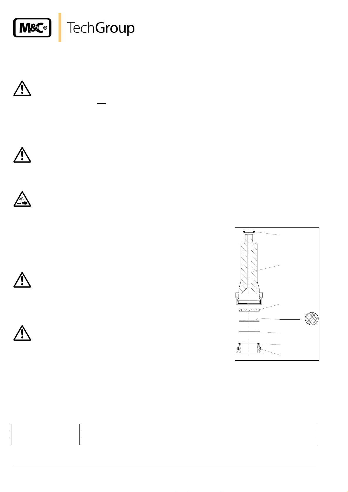
Mounting Instruction Water-Stop CLF-5/W
The following instruction shows the mounting of the PTFE diaphragm into the liquid particle filter type CLF-5/W.
The system must be checked directly when flow is interrupted. A water breakthrough can damage
the analyser(s). Pay attention to absolutely cleanness when mounting the diaphragm.
Contaminations affect the function of the Water-Stop.
The maximum working pressure is 2bar absolute and the maximum temperature is +80°C.
Aggressive condensate possible. Wear safety glasses and protective clothes!
The following steps have to be carried out:
• Unscrew the filter glass counter-clo ckwise.
• Unscrew the filter element holder d.
O-ring
Part No.:91E4010
• Unlock the press screw h and dismantle the glass frit c with the
diaphragm filter e and the flat ring disc f.
Filter element holder
Part No.:90F3500
When re-fitting the glass frit be sure that the smooth side is opposite
to the filter element holder.
• Fit the diaphragm filter with the weft side towards the glass frit.
• Place the flat ring disc on the diaphragm filter.
When changing the O-ring of the press screw do not roll up. In case
other materials for the O-ring have been used due to technical
reasons, this is noted on the type plate. Please pay attention to this
and specify when ordering replacement parts.
Glass frit
Part No.:90F3520
Surface
Diaphragm filter
Part No.:90F3510
Plain washer
Part No.:90F3525
O-ring
Part No.:90F3515
Press screw
Part No.:90F3505
Screw the press screw by hand into the filter element holder up to the diaphragm filter.
The assembly of the fluid particle filter happens in the opposite way.
Recommended spare parts
Wear, tear and replacement part requirements depend on specific operating conditions.
Part No. Description
90 F 3530 Spare part set consisting of: glass frit c, diaphragm filter e, flat ring disc f and O-ring g
90 F 3535 Spare part set consisting of: diaphragm filter e, flat ring disc f
Gas sampling and gas conditioning technology 5-1.10.7-ME
M&C TechGroup Germany GmbH z Rehhecke 79 z 40885 Ratingen z Germany z Tel.: (0)2102/935-0 z Fax: (0)2102/935-111 z www.mc-techgroup.com
 Loading...