

Page 1

CLF-5
Embracing Challenge
Fluid Particle Filter Series CLF®
Version CLF-5, CLF-5/W for removal of aerosols from gases
Special Features
High retention rate of 99,9999% for
particles > 0,1µm
Also with integrated hydrophobic dia-
phragm for analyser protection
Condition of lter element visible from
outside
Easy change of lter element
Wall mounting
Application
The M&C fluid particle filter CLF-5, CLF-5/W
is suitable for filtration of fluid particles of
all types and is recommended for sample
gases with an acid dew point above 100 °C.
Examples are measurements in flue gas of
heavy oil and black coal combustions.
The filter separates the aerosols (very fine
fluid particles) which still pass the gas cooler.
The most effective position of the CLF-.. filter is downstream the sample conditioning
close to the flowmeter of the analyser. For
additional system protection we provide the
version CLF-5/W with integrated hydrophobic
diaphragm, working as a liquid stop.
Description
The filter element of the M&C fluid particle
filter is constructed in two sections with a
flow direction from the inside to the outside
of the filter element. The inner, very fine, fibre
layer binds the fluid particles suspended in
the gas and leads them together with the gas
flow to the outer, larger layer. On their way
through the filter element, the very fine fluid
particles accumulate with others and form
droplets. The vertical flow direction and the
force of gravity cause the droplets to drip into
the filter pot.
The filter element remains fully effective even when completely saturated
with fluid. If it is not effected by solid particles, the lifetime is nearly unlimited.
The compressed Micro-Fibres are made with
binding of PVDF in order to prevent influences on the sample gas.
The version CLF-5/W is equipped with an
integrated liquid stop for water and water
identical liquids. The modified filter element clamp has a protective hydrophobic diaphragm. In case the sample conditioning system does not work proper, the
CLF-5/W will stop the liquid in front of the
filter outlet.
The condition of the filter is visible through
the glass body without opening the filter.
The separated acid mist can continuously be
discharged with an external mounted peristaltic pump SR25.1 (option) connected by a GL25
adapter. No tools are required to change the
filter element. The optimised position of the
O-ring always guarantees a safe sealing of
the filter body to the filter head. The filter
in- and outlet can be turned about 180 °
on the mounting bracket to achieve easy
mounting and flexible adaptation to local
circumstances.
Handle with care! Danger of acid burns!
Technical specications and illustrations are without
obligation, subject to modications. 09.96/06.06
M&C TechGroup Germany GmbH • Rehhecke 79 • 40885 Ratingen • Germany
info@mc-techgroup.com • www.mc-techgroup.com • Fon +49 2102 935-0 • Fax +49 2102 935-111
7.7
Page 2
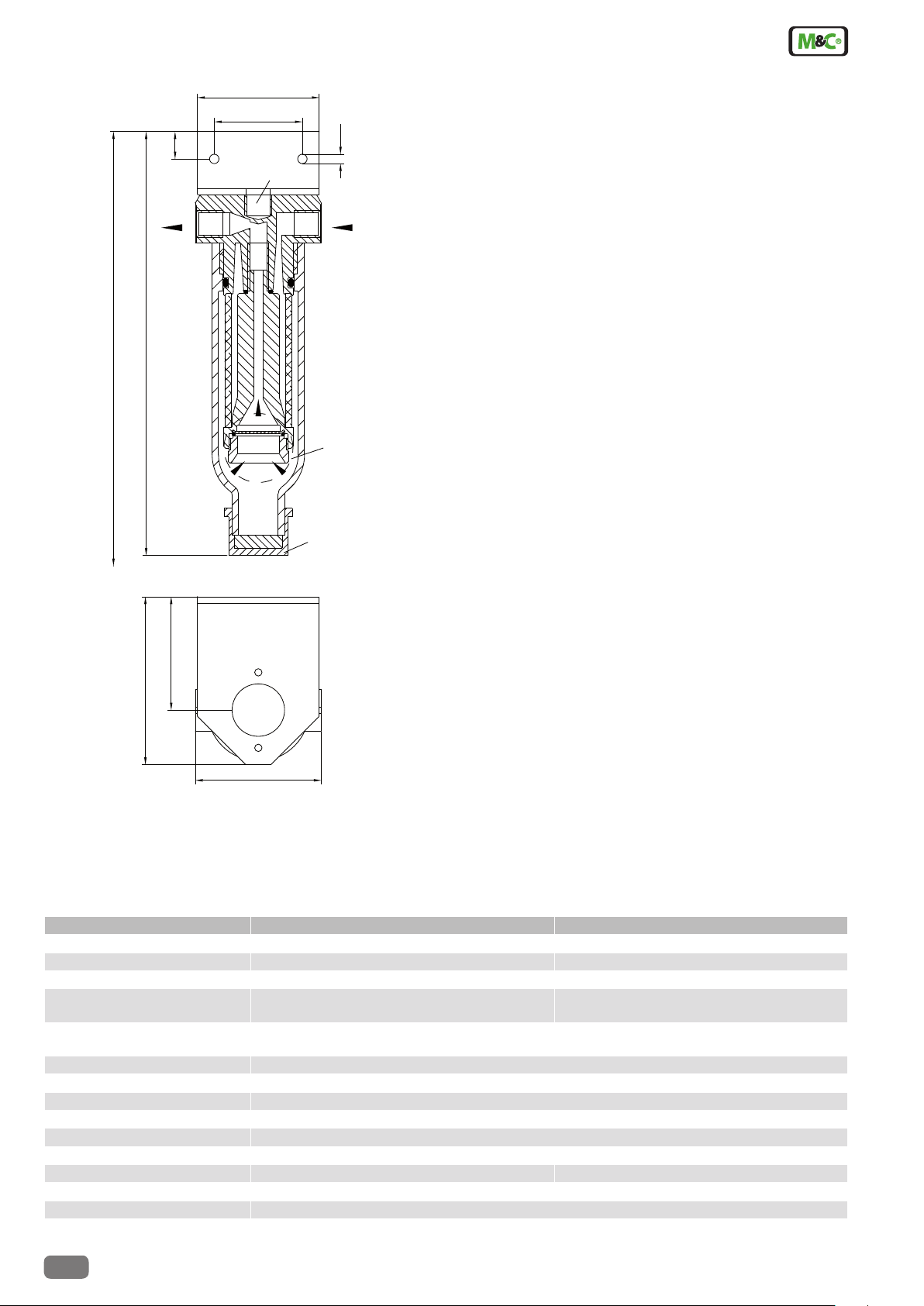
Dimensions
13
58
42
ø 5
G1/4"
310
G1/4"
202
GL25
*
54
80
ø 60
* Constructional size
Dimensions in mm
Protective hydrophobic diaphragm unit only with version CLF-5/W.
On request the G1/4“i thread connection can be used as a
second gas outlet through a ø 5 mm boring.
Technical Data
Fluid particle filter CLF-5 CLF-5/W
Part No. 03F3000 03F3005
Option: Water stop NO YES
Gas flow max. 300 Nl/hr max. 200 Nl/hr
Gas pressure 0,2-2 bar abs.
∆P max. 1,0 bar
Differential pressure with
a new filter element, with air, 20 °C
Sample temperature max. +80 °C
Ambient temperature 0 °C to +60 °C
Storage temperature -25 °C to +80 °C
Filter element/Retention rate 2-layers CLF-5 / 99,9999% for particles >0,1 µm
Filter dead volume 70 cm
Reservoir capacity for liquid 20 ml
Material of sample contacting parts PVDF, glass, FPM PVDF, glass, FPM, PTFE, Polyester
Sample gas-/drain connection G 1/4"i DIN ISO 228/1 / GL25 cap
Type of mounting/Weight wall mounting/approx. 0,3 kg
3 6 10 mbar
100 200 300
3
0,3-2 bar abs.
∆P max. 0,5 bar
17 35 mbar
100 200
7.7
M&C TechGroup Germany GmbH • Rehhecke 79 • 40885 Ratingen • Germany
info@mc-techgroup.com • www.mc-techgroup.com • Fon +49 2102 935-0 • Fax +49 2102 935-111
Technical specications and illustrations are without
obligation, subject to modications. 09.96/06.06
 Loading...