

Page 1
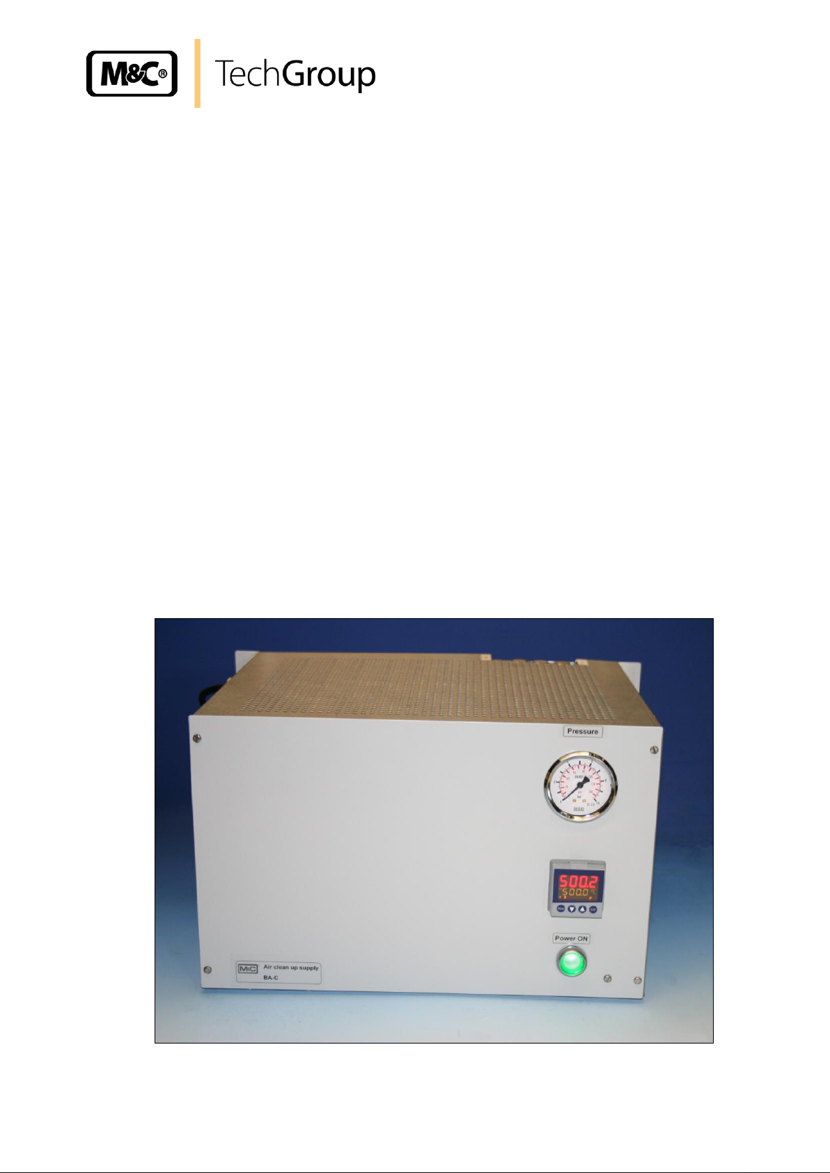
Instruction Manual
Air Conditioning Unit Series BA
Version BA-C
Gas sampling and gas conditioning technology 10-1.1.1-ME
Page 2

2
Content
1 General information ............................................................................................................... 4
2 Declaration of conformity ...................................................................................................... 4
3 Safety instructions ................................................................................................................. 5
4 Warranty .................................................................................................................................. 5
5 Used terms and signal indications ....................................................................................... 6
6 Introduction ............................................................................................................................. 7
7 Function .................................................................................................................................. 7
8 Technical Data ........................................................................................................................ 8
9 Description .............................................................................................................................. 9
10 Receipt and storage ............................................................................................................. 10
11 Installation notes .................................................................................................................. 10
11.1 Rebuilding for 19“-rack-mounting .................................................................................... 11
12 Supply connections ............................................................................................................. 11
12.1 Mounting and connection of the filter .............................................................................. 11
12.2 Hose connections ............................................................................................................ 12
12.3 Electrical connections ...................................................................................................... 12
13 Initial operation ..................................................................................................................... 13
14 Switch off .............................................................................................................................. 13
15 Maintenance .......................................................................................................................... 13
15.1 The external particle-condensate-filter ............................................................................ 14
15.1.1 Drain of the condensate ............................................................................................... 14
15.1.2 Change of the filter cartridge ....................................................................................... 14
16 Appendix ............................................................................................................................... 15
List of Illustrations
Figure 1 Function diagram of BA-C air conditioning units .............................................................. 7
Figure 2 BA-C air conditioning unit ................................................................................................. 9
Figure 3 Rebuilding the mounting brackets .................................................................................. 11
Figure 4 Hose connections for wall mounting or 19“-rack-mounting ............................................ 12
Figure 5 Circuit diagram BA-C ...................................................................................................... 16
Gas sampling and gas conditioning technology 10-1.1.1-ME
Page 3

3
This Operating Manual does not claim completeness and may be
subject to technical modifications.
© 09/2007 M&C TechGroup Germany GmbH. Reproduction of this
document or its content is not allowed without permission from M&C.
1st Edition: 09/2007
Dear customer,
we have made up this operating manual in such a way that all necessary information about the
product can be found and understood quickly and easily.
Should you still have any question, please do not hesitate to contact M&C directly or go through your
appointed dealer. Respective contact addresses are to be found in the annexe to this operating
manual.
Please also contact our homepage www.mc-techgroup.com for further information about our
products. There, you can read or download the data sheets and operating manuals of all M&C
products as well as further information in German, English and French.
Gas sampling and gas conditioning technology 10-1.1.1-ME
Page 4
4
Head Office
M&C TechGroup Germany GmbH Rehhecke 79 40885 Ratingen Germany
Telephone: 02102 / 935 - 0
Fax: 02102 / 935 - 111
E - mail: info@mc-techgroup.com
www.mc-techgroup.com
1 GENERAL INFORMATION
The product described in this operating manual has been examined before delivery and left our works
in perfect condition related to safety regulations. In order to keep this condition and to guarantee a
safe operation, it is important to heed the notes and prescriptions made in this operating manual.
Furthermore, attention must be paid to appropriate transportation, correct storage, as well as
professional installation and maintenance work.
All necessary information a skilled staff will need for appropriate use of this product are given in this
operating manual.
2 DECLARATION OF CONFORMITY
CE - Certification
The product described in this operating manual complies with the following EC directives:
EMV-Instruction
The requirements of the EC directive 2004/108/EC “Electromagnetic compatibility“ are met.
Low Voltage Directive
The requirement of the EC directive 2006/95/EC “Low Voltage Directive“ are met.
The compliance with this EC directive has been examined according to DIN EN 61010.
Declaration of conformity
The EU Declaration of conformity can be downloaded from the M&C homepage or directly requested
from M&C.
Gas sampling and gas conditioning technology 10-1.1.1-ME
Page 5

5
3 SAFETY INSTRUCTIONS
Please take care of the following basic safety procedures when mounting, starting up or
operating this equipment:
Read this operating manual before starting up and use of the equipment. The information and
warnings given in this operating manual must be heeded.
Any work on electrical equipment is only to be carried out by trained specialists as per the regulations
currently in force.
Attention must be paid to the requirements of VDE 0100 (IEC 364) when setting high-power electrical
units with nominal voltages of up to 1000 V, together with the associated standards and stipulations.
Check the details on the type plate to ensure that the equipment is connected to the correct mains
voltage.
Protection against touching dangerously high electrical voltages:
Before opening the equipment, it must be switched off and hold no voltages. This also applies to any
external control circuits that are connected.
The device is only to be used within the permitted range of temperatures and pressures.
Check that the location is weather-protected. It should not be subject to either direct rain or moisture.
The air conditioning unit BA-C must not be used in hazardous areas.
Installation, maintenance, monitoring and any repairs may only be done by authorized personnel with
respect to the relevant stipulations.
4 WARRANTY
If the equipment fails, please contact M&C directly or else go through your M&C authorised dealer.
We offer a one year warranty as of the day of delivery as per our normal terms and conditions of sale,
and assuming technically correct operation of the unit. Consumables are hereby excluded. The terms
of the warranty cover repair at the factory at no cost or the replacement at no cost of the equipment
free ex user location. Reshipments must be send in a sufficient and proper protective packaging.
Gas sampling and gas conditioning technology 10-1.1.1-ME
Page 6

6
DANGER!
This means that death, severe physical injuries and/or important
material damages will occur in case the respective safety
measures are not fulfilled.
WARN I N G !
This means that death, severe physical injuries and/or important
material damages may occur in case the respective safety
measures are not fulfilled.
CARE!
This means that minor physical injuries may occur in case the
respective safety measures are not fulfilled.
CARE!
Without the warning triangle means that a material damage may
occur in case the respective safety measures are not met.
ATTENTION!
This means that an unintentional situation or an unintentional status
may occur in case the respective note is not respected.
NOTE!
These are important information about the product or parts of the
operating manual which require user‟s attention.
SKILLED STAFF
These are persons with necessary qualification who are familiar with
installation, use and maintenance of the product.
5 USED TERMS AND SIGNAL INDICATIONS
Gas sampling and gas conditioning technology 10-1.1.1-ME
Page 7

7
1 = Connection for oil-free
compressed air resp.
instrument air
2 = Outlet
3 = Condensate out
FI1 = Catalyst
FI2/3 = Adsorber
FI4 = Buffer vessel
P 1 = Manometer
S 2 = Pressure switch
Y1,2,3 = Solenoid valve
YA1 = Filter
YA2 = Pressure controller
Y4,Y6 = Needle valve
6 INTRODUCTION
The M&C BA-C air conditioning unit has been designed especially for applications where dry, cleaned
and hydrocarbon-free air is required, independent of gas cylinders.
Typical applications are hydrocarbon measurements with flame ionisation detectors (FID) and use as
a zero gas generator for the calibration of infrared (IR) analyzers or for production of dilution gas for
M&C dilution probes.
The M&C BA-C air conditioning units are compact, operator and service-friendly 19” plug-in units for
19”-rack mounting or wall mounting.
7 FUNCTION
Figure 1 Function diagram of BA-C air conditioning units
The functional principle of the M&C combustion air conditioning unit is divided into two sections (see
Figure 1):
Hydrocarbon elimination section
Gas conditioning section
Hydrocarbon elimination section:
Catalytic oxidation Fl1 of hydrocarbons at a temperature of 932°F at the surface of the
platinum/palladium filling. The optimum catalyst temperature is adjusted ex works at the temperature
controller B1 of the air conditioning unit.
Gas sampling and gas conditioning technology 10-1.1.1-ME
Page 8

8
Combustion Air Conditioning Unit
Type BA-C 230V
Type BA-C 115V
Part No.:
60 A 2000
60 A 2200
Inlet pressure
Instr. air 73 psi up to 145 psi
Flow rate air
maximum 15 Nl/min
Ambient temperature
+41°C to +104°F
Ready for operation
approx. 15 min.
Catalyst
Platinum/Paladium on Al2O3-Support
Temperature of catalyst
932°F
Contamination of catalyst
Halogene, silicon, lead, phosphoric substances
Adsorber
Molecular sieve
Purity of air
< 2 ppm CO2
Storage temperature
-13°C to +149°C
Relative humidity
< 75 % avoid condensation
Gas connection „Inlet‟
G1/4“i
Gas connection „Outlet‟
G1/4“i
Power supply / Power consumption
230V 48-62 Hz 560VA
115V 48-62 Hz 150VA
Electrical connection
Mains cable 3x 1,5² 3 m length with cable end contact
Status cable 2x 0,75² 3m length with cable end contact
Electrical protection
1 x 4AT
Status contact output
for pressure and temperature
1 NO contact - potential free, max . 24V, 1A
Protection
IP 20 (EN 60529)
Dimensions
19" housing 6 U (HE), depth 375 mm
Weight
24,5 kg
Colour of front plate
Ral 7035
Noise
Approx. 70db(A) cyclic 5min
Electrical equipment standard
EN 60204-1, EN 57721
Gas conditioning section:
The second cleaning stage are two mol sieve columns removing CO2 and moisture (Fl2 and FI3)
being switched and purged resp. regenerated cyclical.
The inlet pressure is 70 - 145 psig. The manometer P1 on the front plate of the BA-C enables the
optical control of the inlet pressure.
The cleaned air is available at the outlet 2. Here a connector G ¼“ i provided by customer can be
mounted.
If the inlet pressure drops to a value below 73 psi or the catalyst temperature falls below 914°F the
gas flow is switched off.
8 TECHNICAL DATA
Gas sampling and gas conditioning technology 10-1.1.1-ME
Page 9

9 DESCRIPTION
B1
P1
S1
9
Figure 2 BA-C air conditioning unit
All controls and indicating elements are arranged easily accessible on the front panel of the
combustion air conditioning unit:
P1: Inlet pressure gauge P1
S1: Main switch S1
B1: Temperature controller with digital temperature display B1
The M&C air conditioning unit BA-C is a compact, easy to handle and maintain wall mounting device.
By rebuilding the mounting brackets the air conditioning unit is also applicable for 19“-rack mounting.
The gas connections at the back (G 1/4“i) can be used for the 19“-mounting and the gas connections
on the top can be used for wall mounting. The electrical connections take place via the fix connected
3m cable at the side of the housing.
The oven temperature is electronically controlled and preset at the factory to +932 °F at the
temperature controller B1 on the front panel.
Remaining the catalyst temperature by 50 °F or the minimum inlet pressure of 73 psi will switch of the
gas flow.
Gas sampling and gas conditioning technology 10-1.1.1-ME
Page 10

10
NOTE!
The air conditioning unit should be stored protected from frost!
NOTE!
The air conditioning unit must only be used in the conditions specified in
the technical data.
The air conditioning unit should be installed away from heat sources and
freely ventilated to prevent any accumulation of heat.
For outdoor installation, the air conditioning unit must be installed in a
housing protected from frost in the winter and sufficiently ventilated in
summer. Exposure to direct sunlight must be avoided.
At the inlet of the device (upstream the filter) a shut off valve shall be
provided
10 RECEIPT AND STORAGE
The BA-C combustion air conditioning unit is a complete, pre-installed unit. The standard catalyst
and adsorber cartridge supplied is already fitted. The filter to be connected upstream is attatched to
the device.
Immediately remove the air conditioning unit and any special accessories carefully from the
packaging and check the contents against the delivery note.
Inspect the unit for possible transport damage and inform the transport insurer concerned
immediately if any damage is noticed.
11 INSTALLATION NOTES
Gas sampling and gas conditioning technology 10-1.1.1-ME
Page 11

11
WARNING!
The input compressed air has to be dry and oil free, because
otherwise the device will be damaged!
19“-Mounting
11.1 REBUILDING FOR 19“-RACK-MOUNTING
The deliverd device is prepared for wall mounting.
For 19“-rack-mounting the two mounting brackets have to be disconnected from the back side and
fixed to the front side.
For one side as a start act as follows:
Unscrew the three screws at the front of the sidewall.
Unsrew the two upper screws at the mounting bracket and only loosen the third to turn the
bracket to the back. Screw in now the two screws again.
Unscrew the lower screw from the bracket and screw it in without the bracket.
Fix the bracket at the front.
Do it the same way at the other side.
This procedure ensures that the back wall remains fixed in the device.
Figure 3 Rebuilding the mounting brackets
12 SUPPLY CONNECTIONS
12.1 MOUNTING AND CONNECTION OF THE FILTER
The separate delivered filter has to be mounted at an easy accessible place and has to be connected
with the inlet of the air conditioning unit. For the filter housing a minimum constructional size of
100mm has to be taken into consideration.
For the connection between filter and the inlet of the conditioning unit two connectors G ¼“-DN4/6
and 2m PTFE tube are enclosed to the delivery. The filter inlet is marked with 1 and the outlet is
marked with 2.
Gas sampling and gas conditioning technology 10-1.1.1-ME
Page 12

12
HINWEIS!
Do not exchange the tube connections for inlet and outlet; the
connections are marked correspondingly.
1 = inlet; 2 = outlet
After connecting all tubings, check the closeness.
WARNING!
Incorrect system voltage can damage the unit. When establishing
connections, check that the system voltage corresponds with the
voltage shown on the type plate!
NOTE!
For the erection of power installations with rated voltages up to
1000V, the requirements of VDE 0100 and relevant standards and
specifications must be observed!
The main circuit is equipped with a fuse corresponding to the
nominal current (over current protection); for electrical details see
technical data.
12.2 HOSE CONNECTIONS
The connection of the air in- and outlet take place on the top for wall mounting and at the back side
for 19“-rack-mounting.
19“-Mounting Wall mounting
Figure 4 Hose connections for wall mounting or 19“-rack-mounting
For rebuilding the connections (G1/4“i) on the top or back side the blind plugs have to be displaced
correspondingly.
— Appropriate connection fittings are optionally available by M&C
12.3 ELECTRICAL CONNECTIONS
The mains connection takes place via the fixed installed 3m mains cable:
brown = L
blue = N
green/yellow = PE
The connection of the status alarm NO takes place via the fixed installed 3m twin core cable.
Gas sampling and gas conditioning technology 10-1.1.1-ME
Page 13

13
WARNING!
The air conditioning unit is operated with min. 73 psi and max.
145 psi inlet pressure.
NOTE!
The maximum gas flow is 15Nl/min.
NOTE!
The place of installation of the air conditioning unit must be
remain free from frost also during time when the unit is switched
off !
WARNING!
The air conditioning is operated with max. 145 psi inlet pressure.
High voltage and high pressure. Disconnect the mains plug and
the pressure air inlet before opening the housing!
13 INITIAL OPERATION
Prior to initial operation, the system and process-specific safety measures must be observed !
The following steps must be carried out prior to initial operation:
Prior to initial operation, compare the system voltage with the voltage shown on the rating plate;
Connect the air conditioning unit to the mains;
Connect status contact ouput, if necessary ;
Operate the “Power/On” switch (green LED lights).
Check the nominal temperature of 500°C at the temperature controller (see Figure 2).
When operational readiness has been reached (about 15 minutes), the 1 lights upin the display.
14 SWITCH OFF
Switch off the device and disconnect the pressure air.
No more particular measures are required for switch off.
15 MAINTENANCE
Before carrying out maintenance work, the system and process-specific safety measures must be
observed!
Gas sampling and gas conditioning technology 10-1.1.1-ME
Page 14

14
WARNING!
Also after switching off the mains voltage touching the catalyst
cartridge can lead to serious burns. Wear protective gloves.
WARNING!
The air conditioning is operated with max. 145 psi inlet pressure.
Before maintaining the filter the device has to be disconnected
from the pressure air.
WARNING!
At a condensate level of 10mm below the Filterelement (see
marking) the condensate has to be drained because otherwise the
air conditioning will be damaged.
15.1 THE EXTERNAL PARTICLE-CONDENSATE-FILTER
15.1.1 DRAIN OF THE CONDENSATE
Disconnect the device from the pressure air supply.
Open drain screw anti clockwise seen from below.
Condensate is draining off.
For the condensate connection a hose connector for tube 4/6mm is exsisting.
15.1.2 CHANGE OF THE FILTER CARTRIDGE
Changing the filter cartridge may be necessary in case of decreasing air flow.
For a change of the filter cartridge the following steps must be carried out:
Disconnect pressure air from the filter
Wait until the pressure in the device has decreased to ambient pressure (control at the
manometer)
Push unlock slider in direction of the arrow
Turn filter housing anti clockwise (seen from below) and remove it downwards
Turn filter cartridge anti clockwise
Touch new filter cartridge only at the lower end
Mount the parts in reverse order
Gas sampling and gas conditioning technology 10-1.1.1-ME
Page 15

16 APPENDIX
Circuit diagram BA-C
More product documentation is available on our Internet catalogue:
www.mc-techgroup.com
15
Gas sampling and gas conditioning technology 10-1.1.1-ME
Page 16

16
Figure 5 Circuit diagram BA-C
Gas sampling and gas conditioning technology 10-1.1.1-ME
 Loading...