

Page 1
Page 2
Page 3
INTRODUCTION
This manual covers only the mechanical aspects of WHR chillers equipped with the
trol. All of the operating, safety control and installation requirements of the
MicroTech
MicroTech
reciprocating chiller con-
control are coveted in the separate
Installation and Maintenance Bulletin 493, which must be consulted before startup and operation is attempted.
GENERAL
McQuay Type WHR SEASONPAK water chillers are designed for indoor installations and are compatible with either
air or water as a condensing medium. Each unit is completely assembled and factory wired before evacuation, charging
and testing. Each unit consists of multiple accessible hermetic
compressors, replaceable tube dual circuit shell-and-tube
evaporator, water cooled condenser, and complete or partial
refrigerant piping depending on the condensing medium.
Liquid line components that are included are manual liquid
line shutoff valves, charging valves, filter-driers, liquid line
solenoid valves,
sightglass/moisture indicators, and balance
DESCRIPTION
port type thermal expansion valves. Other features include
compressor crankcase heaters, recycling
pumpdown
“on” or “off” seasons, compressor lead-lag switch to alternate the compressor starting sequence, and sequenced starting of compressors.
The electrical control center includes. all safety and operat-
ing controls necessary for dependable automatic operation.
Compressors are not fused, but may be protected by optional circuit breakers, or may rely on the field installed
fused disconnect for protection.
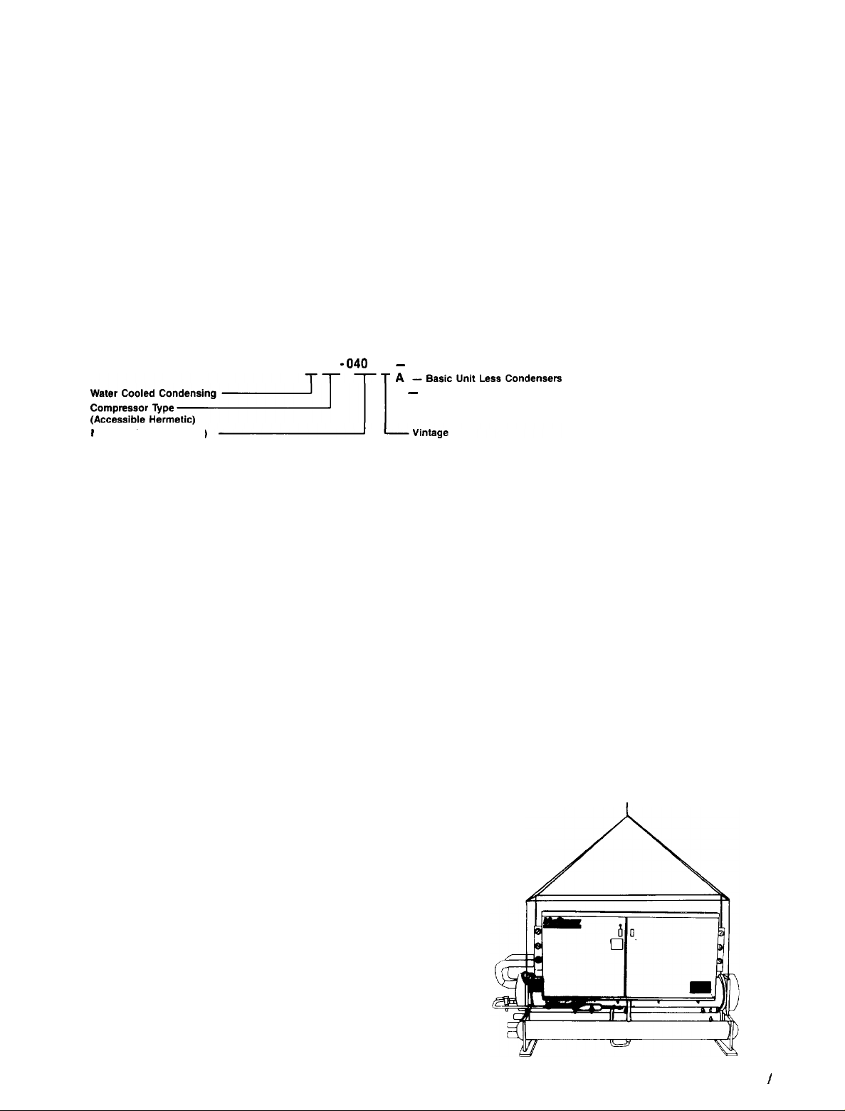
NOMENCLATURE
W HR
- 040
D W
-
Nominal Capacity (Tons)
Basic Unit with Single Water Cooled
H
-
Basic Unit with Dual Water Cooled Condensers per Refrigerant Circuit
Condenser per Refrigerant Circuit
INSPECTION
When the equipment is received, all items should be careful-
ly checked against the bill of lading to insure a complete
ship-
ment. All units should be carefully inspected for damage upon
arrival. All shipping damage should be reported to the
car-
rier and a claim should be filed. The unit serial plate should
be checked before unloading the unit to be sure that it agrees
with the power supply available. Physical damage to unit after
acceptance is not the responsibility of McQuay.
NOTE: Unit shipping and operating weights are available
in the physical data table (pages 21 through 23).
during
INSTALLATION
NOTE: Installation and maintenance are to be performed only by qualified personnel who are familiar with local codes
and regulations, and experienced with this type of equipment. CAUTION: Sharp edges are a potential injury hazard.
Avoid contact.
HANDLING
Every model WHR SEASONPAK water chiller with water
cooled condensers (Arrangements W and H) is supplied with
a full refrigerant charge. A holding charge is supplied in
condenserless models (Arrangement A). For shipment the charge
is contained in the condenser and is isolated by the manual
condenser liquid valve and the compressor discharge service valve.
MOVING
The McQuay SEASONPAK water chiller is mounted on heavy
wooden skids to protect the unit from accidental damage and
to permit easy handling and moving.
It is recommended that all moving and handling be performed with the skids under the unit when possible and that
the skids not be removed until the unit is in the final location.
When moving the unit, dollies or simple rollers can be
used under the skids.
Never put the weight of the unit against the control box.
In moving, always apply pressure to the base on skids only and not to the piping or shells. A long bar helps move the
unit easily. Avoid dropping the unit at the end of the roll.
If the unit must be hoisted, it is necessary to lift the unit
by attaching cables or chains at the lifting holes in the
evaporator tube sheets. Spreader bars must be used to protect the control cabinet and other areas of the chiller (see
Figure 1).
Should the unit be damaged, allowing the refrigerant to
escape, there may be danger of suffocation in the equipment
area since the refrigerant will displace the air. Avoid exposing an open flame to refrigerant. Care should be taken to avoid
rough handling or shock due to dropping the unit. NEVER
LIFT, PUSH OR PULL UNIT FROM ANYTHING OTHER
THAN THE BASE.
THE UNIT
Figure 1.
I
IM 508 / Page 3
Page 4
Do not attach slings to piping or equipment. Move unit in
the upright horizontal position at all times. Set unit down gently
when lowering from the trucks or rollers.
240D,
NOTE: On unit sizes 120 through
ordered with the
LOCATION
Unit is designed for indoor application and must be located
in an area where the surrounding ambient temperatures are
40°F or above. A good rule of thumb is to place units where
ambients are at least 5 degrees above the leaving water
temperature.
Because of the electrical control devices, the units should
not be exposed to the weather. A plastic cover over the
con-
optional acoustical enclosure, there will be extension brackets
attached to the evaporator tube sheets. These brackets will
be used for hoisting the unit and should be removed when
unit is in place.
trol box is supplied as temporary protection during transfer.
A reasonably level and sufficiently strong floor is all that
is required for the SEASONPAK water chiller. If necessary,
additional structural members should be provided to transfer
the weight of the unit to the nearest beams.
NOTE: Unit shipping and operating weights are available
in the physical data table, pages 21 through 23.
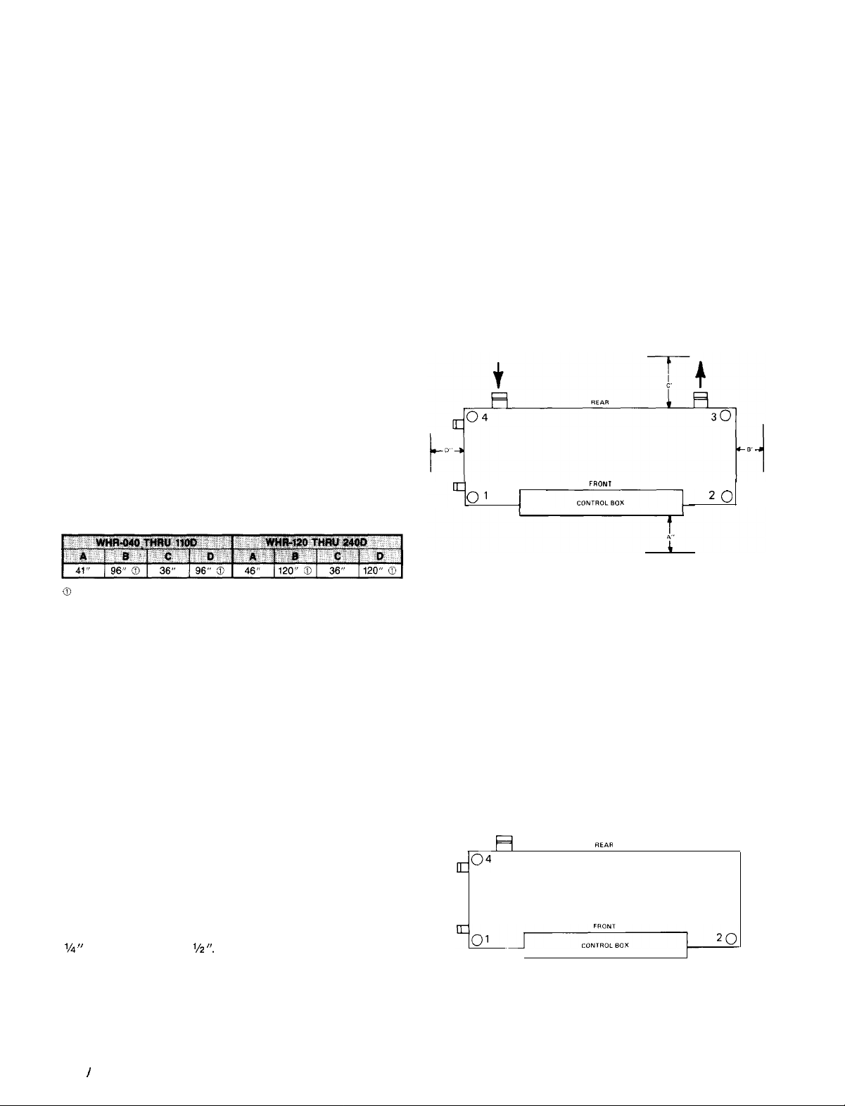
SPACE REQUIREMENTS FOR
The chilled water piping for all units enters and leaves the
cooler from the rear, with the control box side being the front
side of the unit. A clearance of 3 to 4 feet should be provided for this piping and for replacing the filter-driers, for servicing the solenoid valves, or for changing the compressors,
should it ever become necessary.
The condenser water piping enters and leaves the shell
from the ends. Work space must be provided in case water
regulating valves are being used and for general servicing.
Clearance should be provided for cleaning condenser tubes
or for removing cooler tubes on one end of the unit as
specified in Table 1. It is also necessary to leave a work area
on the end opposite that used for replacement of a cooler tube.
Table 1. Minimum recommended clearance requirements
0
Minimum clearance required for removal and replacement of cooler tubes
(either end).
PLACING THE UNIT
The small amount of vibration normally encountered with the
SEASONPAK water chiller makes this unit particularly desirable for basement or ground floor installations where the unit
can be bolted directly to the floor. The floor construction
should be such that the unit will not affect the building
struc-
ture, or transmit noise and vibration into the structure. See
CONNECTIONS AND SERVICING
Figure 2. Clearance requirements
FRONT
0'
I
20
vibration isolator section for additional mounting information.
240D,
NOTE: On the WHR 120D thru
shipping bolts are
used to secure the compressor rails to the evaporator
brackets. Remove these and discard after unit is mounted and
before unit is started.
Rubber-in-shear or spring isolators can be furnished and field
placed under each corner of the package. It is recommended that a rubber-in-shear pad be used as the minimum
isolation on all upper level installations or areas in which
tion transmission is a consideration.
Transfer the unit as indicated under “Moving the Unit.” In
all cases, set the unit in place and level with a spirit level.
When spring type isolators are required, install springs running under the main unit supports. Adjust spring type mountings so that upper housing clears lower housing by at least
l/4 ”
and not more than
l/z “.
A rubber anti-skid pad should be
used under isolators if hold-down bolts are not used.
Vibration eliminators in all water piping connected to the
SEASONPAK water chiller are recommended to avoid straining the piping and transmitting vibration and noise.
I
Page 4
IM 508
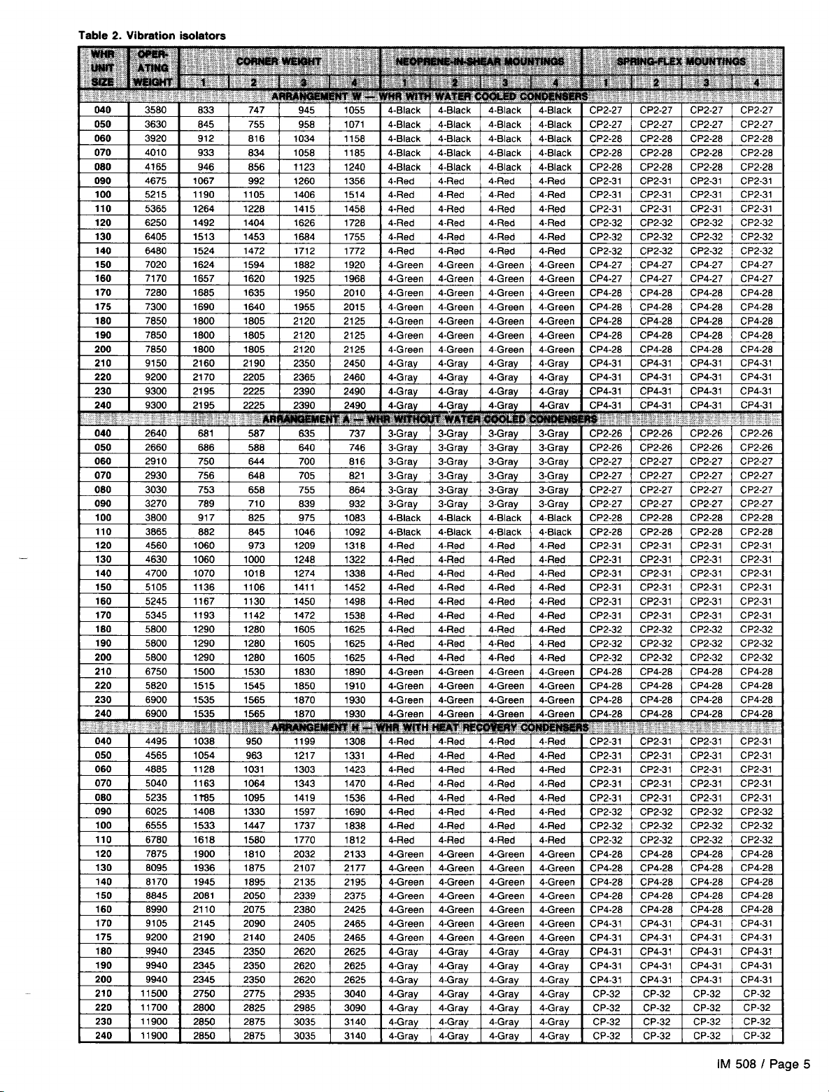
VIBRATION ISOLATORS
Figure 3. Isolator Locations
vibra-
;04
REPlR
a
30
Page 5
Page 6

Table 3. Spring Flex Isolators
Figure 4. Spring Flex Mountings
POSITIONING PIN
ADJUST MOUNTING SO UPPER
HOUSING CLEAR3 LOWER HOUSING
SY
‘/2”
DIA
AT LEAST %S 8 NOT
ACOUSTICAL NON-SKID
NEOPRENEPAD
WATER PIPING
GENERAL
Since regional piping practices vary considerably, local ordinances and practices will govern the selection and installation of piping. In all cases local building and safety codes and
ordinances should be studied and complied with.
All piping should be installed and supported to prevent the
unit connections from bearing any strain or weight of the
system piping.
Vibration eliminators in all water piping connected to the
unit are recommended to avoid straining the piping and
transmitting pump noise and vibration to the building
structure.
It is recommended that temperature and pressure indicators
be installed within 3 feet of the inlet and outlet of the shells
to aid in the normal checking and servicing of the unit.
A strainer or some means of removing foreign matter from
Figure 5. Single Neoprene-in-Shear
Mounting
“S” DIA
POSITIONING PIN
“D” D,A
the water before it enters the unit or the pump is recommended. It should be placed far enough upstream to prevent
cavitation at the pump inlet (consult pump manufacturer for
recommendations). The use of a strainer will prolong pump
life and thus keep system performance up.
A preliminary leak check of the water piping should be
made before filling the system.
Shutoff valves should be provided at the unit so that normal servicing can be accomplished without draining the
system.
A WATER FLOW SWITCH OR PRESSURE DIFFERENTIAL
SWITCH MUST BE MOUNTED IN THE WATER LINES TO
THE EVAPORATOR TO ASSURE WATER FLOW BEFORE
STARTING THE UNIT
CHILLED WATER PIPING
The water flow entering the cooler must always be on the end
nearest the expansion valves and cooler refrigerant connec-
tions to assure proper expansion valve operation and unit
capacity (see pages 16 thru 20).
Design the piping so that it has a minimum number of
changes in elevation. Include manual or automatic vent valves
at the high points of the chilled water piping, so that air can
be vented from the water circuit. System pressures can be
Page 6
I
IM 508
maintained by using an expansion tank or a combination
pressure relief and reducing valve.
All chilled water piping should be insulated to prevent condensation on the lines. If insulation is not of the self-contained
vapor barrier type, it should be covered with a vapor seal.
Piping should not be insulated until completely leak tested.
Vent and drain connections must extend beyond proposed insulation thickness for accessibility.
Page 7
CHILLED WATER SENSOR
On units WHR-040D thru
240D.
the chilled water sensor is
factory installed in the leaving water connection on the
evaporator. For detailed specifications regarding the chilled
water sensor or any other sensors/transducers, refer to IM 493.
Care should be taken not to damage the sensor cable or leadwires when working around the unit. It is also advisable to
check the leadwire before running the unit to be sure that it
is firmly anchored and not rubbing on the frame or any other
component. Should the sensor ever be removed from the well
for servicing, care should be taken as not to wipe off the heat
conducting compound supplied in the well.
NOTE: See IM 493 for additional thermostat information.
CAUTION: The thermostat bulb should not be exposed to
water temperatures above 125°F since this will damage the
control.
FLOW
A WATER FLOW SWITCH MUST SE MOUNTED in either the
entering or leaving water line to insure that there will be ade-
quate water flow and cooling load to the evaporator before
the unit can start. This will safeguard against slugging the
compressors on startup. It also serves to shut down the unit
in the event that water flow is interrupted to guard against
evaporator freeze-up.
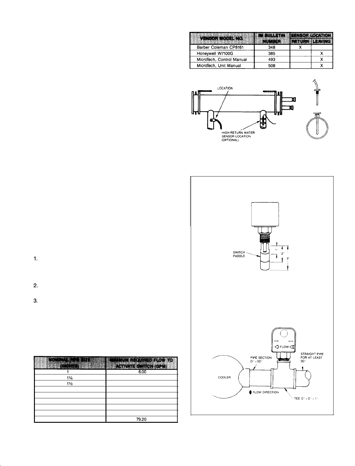
A flow switch is available from under ordering number
1750338-00. It is a “paddle” type switch and adaptable to any
pipe size from
1”
to 6” nominal. Certain minimum flow rates
are required to close the switch and are listed in Table 6. Installation should be as shown in Figure 7. The flow switch
should be wired per actual unit wiring diagram found on the
inside of the unit control panel door or refer to IM 493.
Apply pipe sealing compound to only the threads of the
switch and screw unit into
Figure
7).
The flow arrow must be pointed in the correct
D”x D”x 1”
reducing tee (see
direction.
Piping should provide a straight length before and after
the flow switch of at least five times the pipe diameter.
Trim flow switch paddle if needed to fit the pipe diameter.
Make sure paddle does not hang up in pipe.
CAUTION: Make sure the arrow on the side of the switch is
pointed in the proper direction of flow. The flow switch is
designed to handle the control voltage and should be connected according to the wiring diagram (see wiring diagram
inside control box door).
Table
Figure 6.
SWITCH
Fioure 7.
5.
Thermostat Well Installation
TEMPERATURE SENSOR
LOCATICJN
FLOW SWITCH
VIEW FROM END OF COOLER
Table 6. Flow Switch Minimum Flow Rates
1
1%
l'h 12.70
2 18.80
2%
3
4
5
24.30
30.00
39.70
58.70
6.00
9.80
IM 508 I Page 7
Page 8
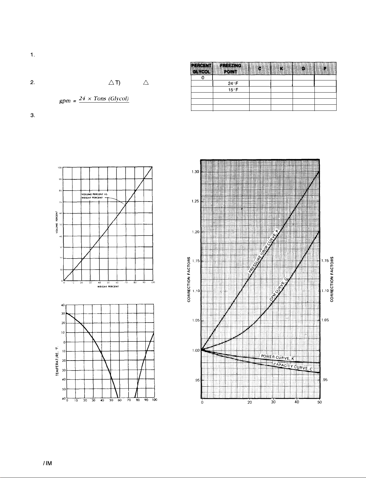
GLYCOL SOLUTIONS
The system glycol capacity, glycol solution flow rate in gpm,
and pressure drop through the cooler may be calculated
us-
ing the following formulas and table.
-
CAPACITY
Capacity is reduced from that with plain
water. To find the reduced value multiply the chiller’s water
system tonnage by the capacity correction factor C to find
the chiller’s capacity in the glycol system.
/I T)
GPM -To determine gpm (or
knowing n T (or gpm)
and tons:
Glvcol gp:pm = 24 x Tons (WW
,
AT
x G (from table)
PRESSURE DROP -To determine glycol pressure drop
through the cooler, enter the water pressure drop graph
on page 9 at the glycol gpm. Multiply the water pressure
drop found there by P to obtain corrected glycol pressure
drop.
Test coolant with a clean accurate glycol solution hydrometer
(similar to that found in service stations) to determine freezing point. Then obtain percent glycol from the freezing point
table below.
0
1
10
1
20
30
40
50
CONDENSER
j
1.000
1
32°F
24'F
15'F
-12°F 0.968
-33°F 0.964
-
1
1.000
/
1
0.990
0.981
4°F 0.974
0.994
'
0.988
0.984
0.981 1.13
0.980
The use of a glycol solution in the heat
1.00
1
1.01
1.04
1.08
1.20
1.00
1
1.06
1
1.12
1.18
1.24
1.30
recovery condensers will not affect heat recovery capacity.
1.30
1.25
PERCENT BY VOLUME
lb
% ETHYLENE GLYCOL BY WEIGHT
i0
3b
1.20
100
4-o
Page 8 I IM 508
Page 9

Page 10
CONDENSER
WATER PIPING
GENERAL - For proper performance, the condenser water
must enter the bottom connection of the condenser. Water
cooled condensers may be piped for use with cooling towers,
well water or heat recovery applications. Cooling tower applications should be made with consideration to freeze protection and scaling problems. For specific applications, contact cooling tower manufacturer for equipment characteristics
and limitations.
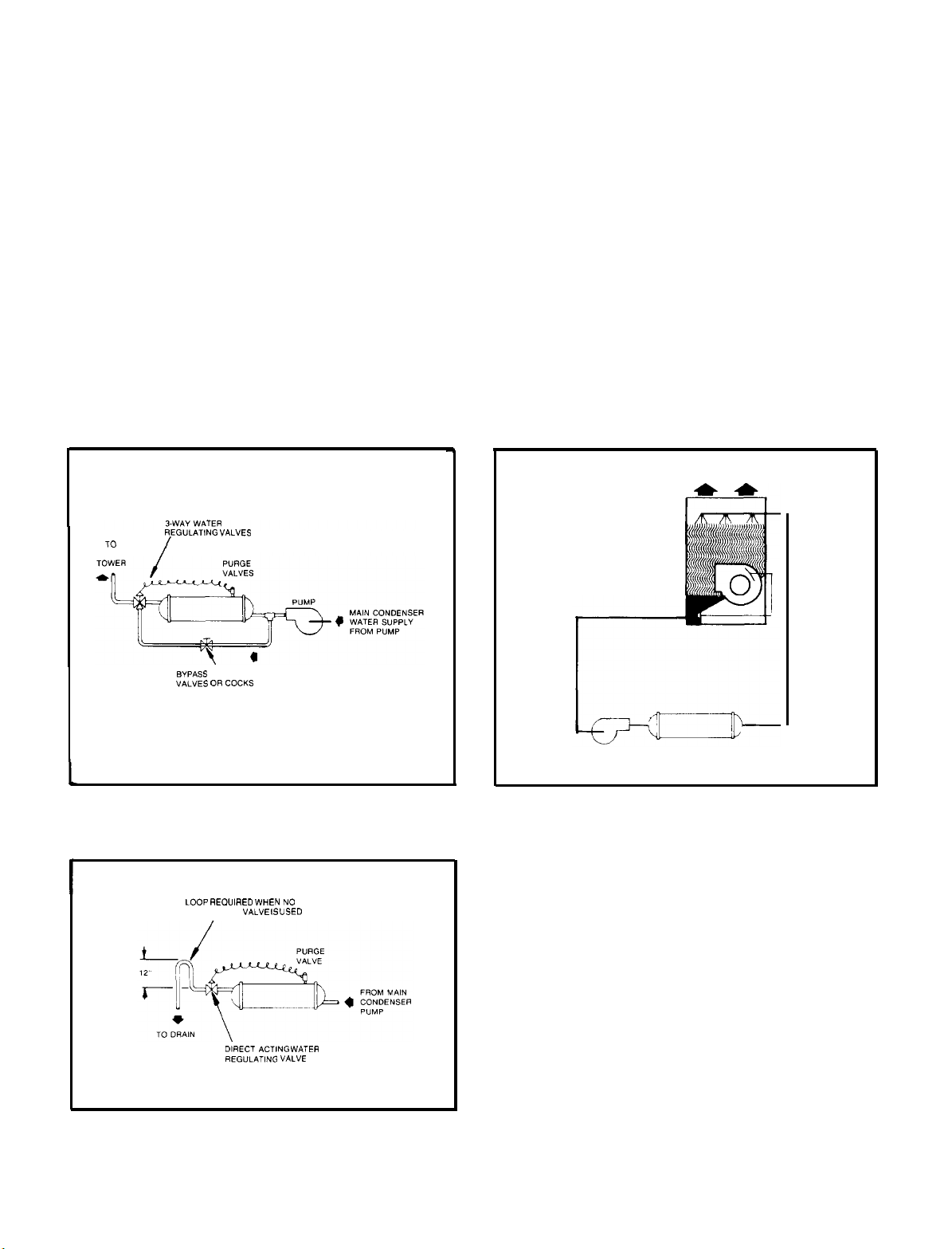
HEAD PRESSURE CONTROL, TOWER SYSTEM
-
Some
means of controlling operating head pressure must be provided. Minimum condensing temperature allowed is 80°F.
Minimum entering tower condenser water temperature is
70°F. Typical systems are shown in Figures 8 and 9. In Figure
8, a three-way pressure actuator water regulating valve is
used for cooling applications, In Figure 9 the capacity of the
cooling tower is controlled through damper and/or fan
COOLING TOWER SYSTEMS-HEAD PRESSURE CONTROL
Figure 8. 3-Way Water Valve
TO
COOLING
REGULATING VALVES
modulation. These typical systems, depending on the specific
application, must maintain a constant condensing pressure,
regardless of temperature conditions and must assure
enough head pressure for proper thermal expansion valve
operation. Note also that both systems assure full water flow
to the tower.
HEAD PRESSURE CONTROL, WELL WATER SYSTEM
-
Where well water is used for condensing refrigerant, a direct
acting water regulating valve is recommended (see Figure
10). The valve is normally installed at the outlet of the con-
denser. On shutdown, the valve will close and, in this way,
prevent water siphoning out of the condenser. Siphoning
causes drying of the waterside of the condenser and rapid
build-up of fouling. When no valve is used, a loop at the outlet
end is recommended (See Figure 10).
Figure
9. Fan
Modulation
COOLING TOWER
BYPASS
BALANCING
VALVES OR COCKS
Figure 10. Well Water Cooling System
I
LOOP REOUIAED WHEN
REGULATING VALVE IS USED
DIRECT
REGULATING VALVE
NO
ACTlNG
WATER
Page 10 I IM 508
Page 11
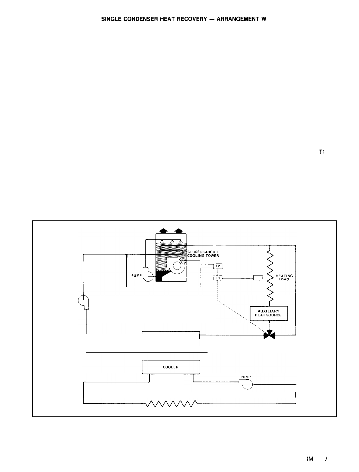
Single circuit heat recovery employs a standard water
cooled chiller equipped with heavier electrical components
and a 380 psig high pressure limit switch. These modifica-
tions allow leaving condenser water temperatures up to 135°F
for building or process heating applications.
A typical heat recovery arrangement will include a closed
circuit cooling tower used to reject unwanted condenser heat
to the outdoor ambient air. The cooling tower should be
sized to reject all the condenser heat during summer design
operation. This insures proper operation in the
nonheatrecovery mode. Use of a closed circuit tower is normally required in order to prevent fouling of heating coils in the heat
recovery loop. Condenser water remains free of contamination from minerals and impurities normally contained in makeup water in an open cooling tower.
If a closed circuit cooling tower is to be located in an ambient temperature below freezing, protection against coil and
sump freeze-up must be provided. Coil freeze protection can
be provided by using a glycol solution or by maintaining a
heat load on the coil
at all times and maintaining water flow
through the coil. Sump water freeze protection can be provided by locating the spray water circulating pump and sump
tank inside a heated space or by placing heating coils in the
sump. Head pressure and water temperature are normally
controlled by the tower capacity control. Adequate capacity
control is usually obtained by fan cycling and regulating
dampers located in the fan discharge. This will maintain a
constant tower water temperature. Consult the closed circuit
manufacturer for information on specific applications.
An auxiliary heat
source is necessary if the available con-
denser heat is not sufficient to satisfy all of the heat load.
The auxiliary heat source must be located between the condenser and the heat load and the control should be inter-
locked with the closed circuit tower to prevent auxiliary
heating while rejecting heat to the ambient.
When the heating load is satisfied, a two-position, three-
way valve is set to divert condenser water around the heat
load and the auxiliary heat source. Whether operating in summer or winter, the chiller is always controlled by the cooling
load and not the heating load.
-
TYPICAL OPERATION
On a call for cooling, the chiller
starts and hot condenser water flows through the diverting
valve to the closed circuit cooling tower rejecting heat to the
outdoors. The tower dampers modulate to maintain a pro-
per entering condenser water temperature which will give ef-
ficient operation by means of the proportional controller T2
located in the outlet fluid line of the tower.
When a heating load is sensed by mode switch
Tl,
the
three-way valve is switched to allow condenser water to flow
through the heating circuit. The proportional controller T2 is
also reset upwards to give the desired water temperature for
heat recovery. The unused condenser heat will be rejected
out through the closed circuit tower. If the condenser heat
of rejection cannot satisfy the heating load after an appropriate delay, the auxiliary heat source will be activated.
Figure
11. Typical Single Condenser (Per Refrigerant Circuit) Heat Recovery
PUMP
HEATRECOVERY
CONDENSER
TWO POSITION
DIVERTING VALVE
COOLING LOAD
NOTE: The schematic shows one refrigerant circuit. Models with two refrigerant circuits have two condensers
IM
508 I Page 11
Page 12
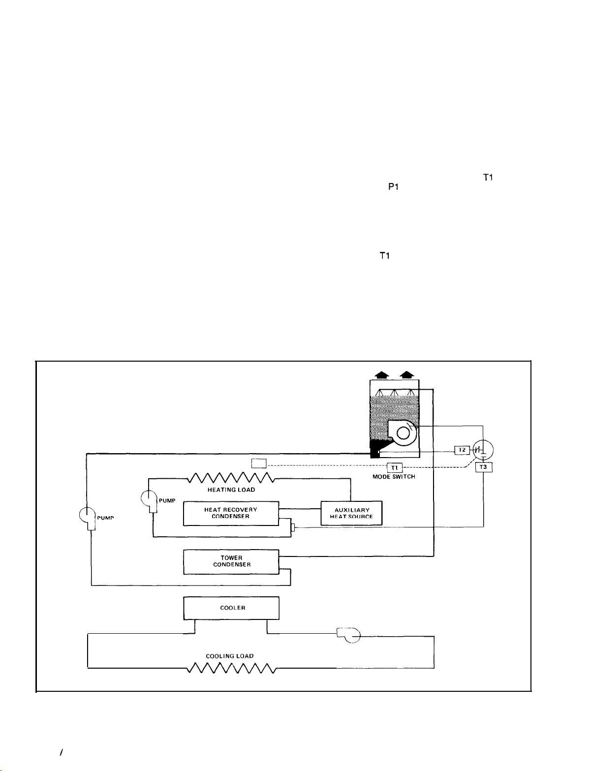
DUAL CONDENSER HEAT RECOVERY - ARRANGEMENT H
Dual condenser heat recovery chiller models have two water
cooled condensers per refrigerant circuit. The upper condenser is the heat recovery condenser and is piped into the
building’s hot water system. The lower condenser is the tower
condenser and is piped to an open cooling tower. Condensing is done in either the tower condenser or heat recovery
condenser, or partial condensing is done in each. The tower
and heat recovery water circuits are independent and do not
intermix. This use of an open tower and the closed heat
recovery loop prevents fouling of the building’s heating
system.
A subcooling circuit is provided in the tower condenser to
provide optimum cooling efficiency. When the unit is
operating on maximum heat recovery, the cooling tower will
be modulated down to its minimum capacity, usually about
5% of full capacity. This provides subcooling for the system
during heat recovery operation. Water can be heated up to
135°F in the heat recovery condensers to satisfy a heating
load. If all of the condenser heat of rejection cannot be
used, the remainder is rejected out through the cooling tower.
The cooling tower should be sized to reject all of the condenser heat during summer operation. Freeze protection for
the cooling tower must be provided if it is to operate in below
freezing temperatures, Adequate capacity control must be
provided to maintain a constant water temperature leaving
the cooling tower. Head pressure and water temperature are
controlled by the tower capacity control. Fan cycling and
modulating fan discharge dampers should be used. Consult
the cooling tower manufacturer for information on specific
applications.
If the available condenser heat cannot satisfy all of the heat
load, an auxiliary heat source must be provided. The auxiliary heat source should be located between the heat
recovery condenser and the heat load and interlocked with
the cooling tower so that auxiliary heat is not being supplied
unless the cooling tower is modulated down all the way. The
chiller operation is always controlled by the building’s cooling load and not the heating load.
TYPICAL OPERATION
-
On a call for cooling the chiller
starts. If a heating load is sensed by mode switch Tl , the heat
recovery water pump Pl will start and the cooling tower
dampers will modulate to control the heat recovery condenser
by means of proportional temperature controller T3. If maximum heat recovery is required, the tower dampers close and
only
the fans shut off. The tower will then provide
subcool-
ing. If more heat is required than the heat recovery condensers can provide, the auxiliary heat source is activated.
When mode switch Tl senses that a heating load no longer
exists, the heat recovery pump shuts off and the cooling tower
modulates to control the entering tower condenser water
temperature by means of proportional controller T2 and a sensor located in the tower sump. Proportional controller T2 is
set at a temperature lower than T3 to provide optimum
efficiency.
Figure
12. Typical Dual Condenser (Per Circuit) Heat Recovery
COOLING TOWER
COOLER
PUMP
Page 12
‘&k’
NOTE: The schematic shows one refrigerant circuit. Heat recovery WHR models with two refrigerant circuits
/
IM 508
have two heat recovery condensers and two tower condensers.
------j
Page 13

REFRIGERANT PIPING
UNIT WITH REMOTE CONDENSER-ARRANGEMENT A
General
cooled condenser, the chillers are shipped containing a
Refrigerant 22 holding charge. It is important that the unit be
kept tightly closed until the remote condenser is installed,
piped to the unit and the high side evacuated.
sized and installed according to the latest
book. It is important that the piping be properly suported with
sound and vibration isolation between tubing and hanger and
that the discharge lines be looped at the condenser and
trapped at the compressor to prevent refrigerant and oil from
draining into the compressor discharge manifold. Looping the
discharge line also provides greater line flexibility.
drier(s), moisture indicator(s), and thermostatic expansion
valve(s) are all provided as standard equipment with the
SEASONPAK water chiller.
condenserless units (Arrangement A) between the liquid line
filter-drier and remote condenser.
charged with Refrigerant 22, then run at design load condi-
tions, adding charge until the liquid line sightglass is clear,
with no bubbles flowing to the expansion valve. Total operating
charge will depend on the air cooled condenser used and
the length of external piping, but generally will be similar to
the water cooled charge shown in Tables 16, 17, and 18, pages
21 through 23.
densers), the installer is required to record the refrigerant
charge by stamping the total charge and the charge per circuit on the serial plate in the appropriate blocks provided for
this purpose.
piping to a remote condenser of some type. The design of
refrigerant piping when using air cooled condensers involves
a number of considerations not commonly associated with
other types of condensing equipment. The following discussion is intended for use as a general guide to sound,
economical and trouble-free piping of air cooled condensers.
and to protect the compressor from damage that may result
from condensing liquid refrigerant in the line during shutdown.
Total friction loss for discharge lines of 3 to 6 psi is considered
good design. Careful consideration must be given for sizing
each section of piping to insure that gas velocities are sufficient at all operating conditions to carry oil. If the velocity in
a vertical discharge riser is too low, considerable oil may col-
lect in the riser and the horizontal header, causing the com-
pressor to lose its oil and result in damage due to lack of
lubrication. When the compressor load is increased, the oil
that had collected during reduced loads may be carried as
a slug through the system and back to the compressor, where
a sudden increase of oil concentration may cause liquid slugging and damage to the compressor.
away from the compressor approximately l/4” per foot or more.
This is necessary to move by gravity any oil lying in the header.
Oil pockets must be avoided as oil needed in the compressor
would collect at such points and the compressor crankcase
may become starved.
horizontal discharge header rise above the center line of the
-
For remote condenser application such as an air
Refrigerant piping, to and from the remote unit, should be
The discharge gas valve(s), liquid line solenoid(s), filter-
A liquid line shutoff valve must be added in the field on
After the equipment is properly installed, the unit may be
NOTE: On the Arrangement A units (units with remote con-
SEASONPAK water chillers without condensers require field
Discharge lines must be designed to handle oil properly
Any horizontal run of discharge piping should be pitched
It is recommended that any discharge lines coming into a
ASHRAE
Hand-
discharge header. This is necessary to prevent any oil or condensed liquid from draining to the top heads when the compressor is not running.
In designing liquid lines it is important that the liquid reach
the expansion valve with no presence of flash gas since this
gas will reduce the capacity of the valve. Because “flashing”
can be caused by a pressure drop in the liquid lines, the
pressure losses due to friction and changes in static head
should be kept to a minimum.
A check valve must be installed in the liquid line in all applications where the ambient temperature can get below the
equipment room temperature. This prevents liquid migration
to the condenser, helps maintain a supply of refrigerant in the
liquid line for initial startup and keeps liquid line pressure high
enough on “off” cycle to keep the expansion valve closed.
On systems as described above, a relief valve or relief type
check valve must be used in the liquid line as shown in piping systems (Figure 14) to relieve dangerous hydraulic
pressures that could be created as cool liquid refrigerant in
the line between the check valve and expansion or shutoff
valve warms up. A relief device is also recommended in the
hot gas piping at the condenser coil as shown in Figures 14
through 16.
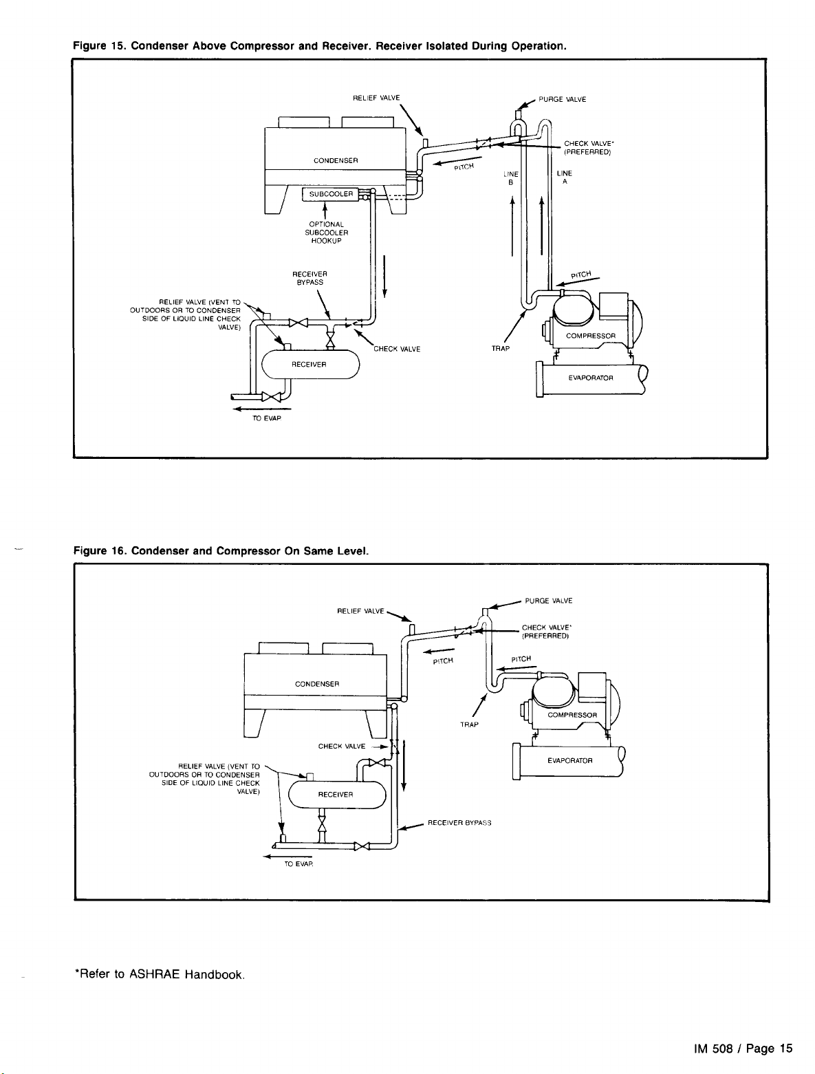
Typical Arrangements
ing arrangement involving a remote air cooled condenser
located at a higher elevation than the compressor and
receiver. This arrangement is commonly encountered when
the air cooled condenser is on a roof and the compressor and
receiver are on grade level or in a basement equipment room.
In this case, the design of the discharge line is very critical.
If properly sized for full load condition, the gas velocity might
be too low at reduced loads to carry oil up through the
discharge line and condenser coil. Reducing the discharge
line size would increase the gas velocity sufficiently at reduced load conditions; however, when operating at full load,
the line might be greatly undersized and thereby create an
excessive refrigerant pressure drop. If this condition occurs,
it can be overcome in one of the two following ways:
1. The discharge line may be properly sized for the desired
pressure drop at full load condition and an oil separator
installed at the bottom of the trap on the discharge line
from the compressor.
2. A double riser discharge line may be used as shown in
Figure 15, page 15. Line ‘A” should be sized to carry the
oil at a minimum load condition and line
sized so that at the full load condition, both lines would
carry oil properly.
Notice in all illustrations that the hot gas line is looped at
the bottom and top of the vertical run. This is done to prevent oil and condensed refrigerant from flowing back into the
compressor and causing damage. The highest point in the
discharge line should always be above the highest point in
the condenser coil; it is advisable to include a purging vent
at this point to release noncondensables from the system.
Figure 16 illustrates another very common application
where the air cooled condenser is located on essentially the
same level as the compressor and receiver. The discharge
line piping in this case is not too critical. The principal problem encountered with this arrangement is that there is frequently insufficient vertical distance to allow free drainage of
liquid refrigerant from the condenser coil to the receiver.
Figure 14 illustrates a typical pip-
-
“B”
should be
IM 508
/ Page 13
Page 14
UNIT WITH FACTORY MOUNTED CONDENSER(S)
Units with factory mounted condensers are provided with
complete refrigerant piping and full operating refrigerant
charge at the factory.
There is a remote possibility on Arrangement W units utilizing low temperature pond or river water as a condensing
medium, and if the water valves leak, that the condenser and
liquid line refrigerant temperature could get below the equipment room temperature on the off cycle. This could open the
expansion valve and cause recycling pumpdown. This
prob-
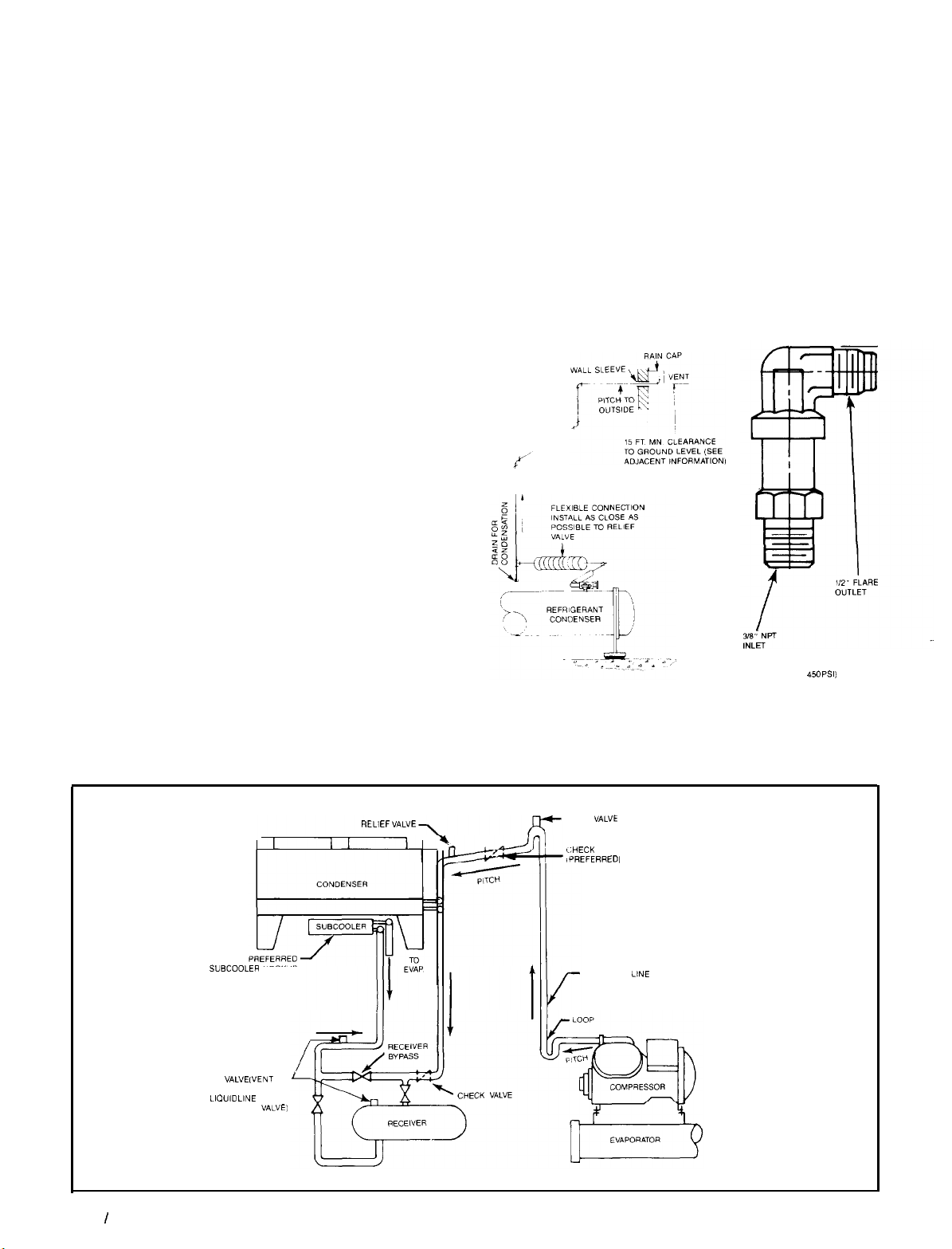
RELIEF VALVE PIPING
The ANSMASHRAE Standard 15-1978 specifies that pressure
relief valves on vessels containing Group 1 refrigerants (R-12,
R-22 and R-500) “shall discharge to the atmosphere at a location not less than 15 feet above the adjoining ground level
and not less than 20 feet from any window, ventilation open-
ing or exit in any building.” The piping must be provided with
a rain cap at the outside terminating point and a drain at the
low point on the vent piping to prevent water buildup on the
atmospheric side of the relief valve. In addition, a flexible pipe
section should be installed in the line to eliminate any piping
stress on the relief valve(s).
The size of the discharge pipe from the pressure relief valve
shall not be less than the size of the pressure relief outlet.
When two or more vessels are piped together, the common
header and piping to the atmosphere shall not be less than
the sum of the area of the relief valve outlets connected to
the header. Fittings should be provided to permit vent piping to be easily disconnected for inspection or replacement
of the relief valve.
only arises during periods when cold water continues to
lem
circulate through the condenser and the unit remains off due
to satisfied cooling load.
If this condition occurs:
1.2.Cycle the condenser pump off with the unit.
Check the liquid line solenoid valve for proper operation.
If these valves are closing liquid tight as designed, no
recycling of
Figure
13. Relief Valve Piping
pumpdown
should occur.
NOTE: Provide adequate fittings in piping to permit repair
or replacement of relief valve.
REFRIGERANT PIPING
Figure 14. Condenser Above Compressor and Receiver
REM3 VALVE
SUBCOOLER HOOKUP
RELIEF
VALVE
OUTDOORS OR TO CONDENSER
SIDE OF IIOUID LINE CHECK
(VENT TO
VALVE)
PURGE
VALVE
GHECK VALVE’
iPREFERRED,
DISCHARGE LINE
RELIEF VALVE
(SET AT 4%
PSI1
Page 14 I IM 508
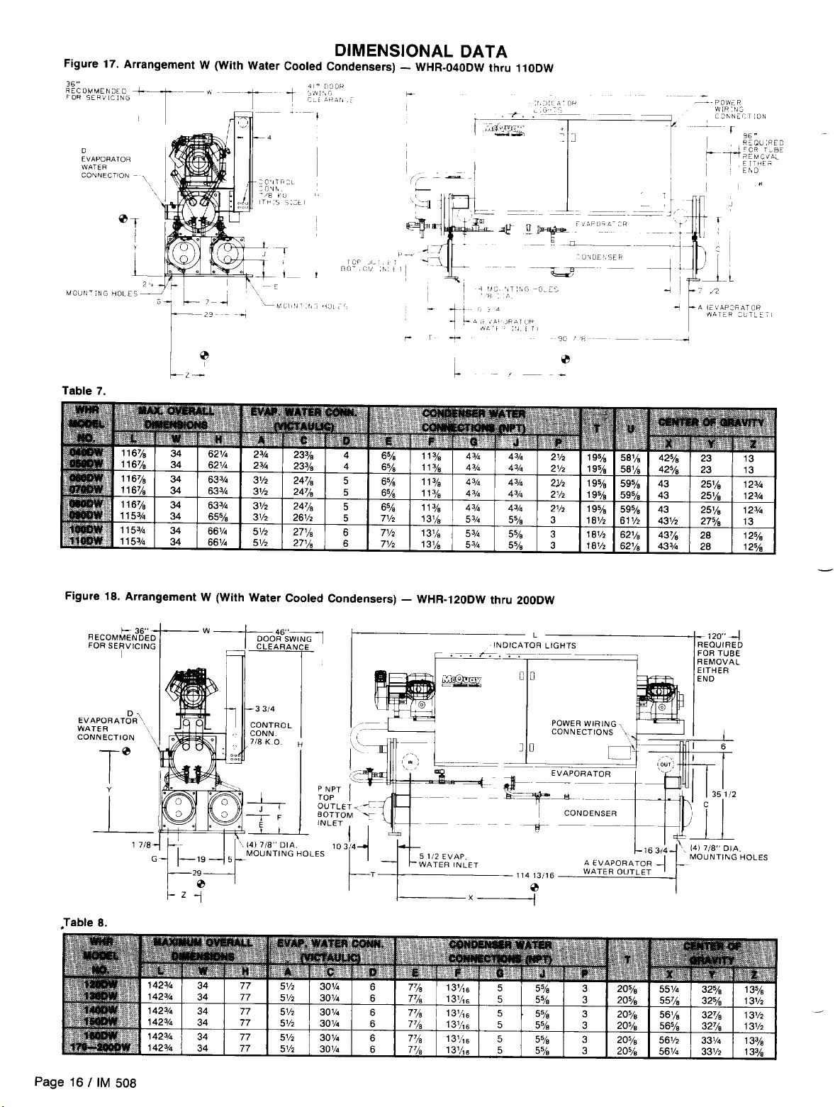
Page 15
Page 16
Page 17

Page 18

Page 19

Page 20

Page 21

Page 22

Page 23

Page 24

Page 25

Page 26

Page 27
Page 28

Page 29

CONTROL CENTER
All electrical controls are enclosed in a control center with
locking, hinged access door(s). A partition separates the ad-
justable safety controls from the starting and operating
con-
trots. A “deadfront” panel covers all starting and operating
controls so that no electrical contacts or terminals are
posed. The deadfront panel is hinged for servicing. The
ex-
ad-
POWER PANEL LAYOUT
Figure 27. WHR-040D thru
Right Side, High Voltage Control Section
1
1lOD
0 0
justable controls are covered and can be adjusted without fear
of contacting line voltage.
IM
Please refer to
493 for control section layout, all low
voltage field wiring and normal sequence of operation for units
equipped with
Figure 28. WHR12OD thru 240D
MicroTech
Right Side, High Voltage Power Section
control.
pq”
&,
WIRING
FIELD WIRING, POWER
The WHR
pressor contactors and power terminal block, designed for
single power supply to unit. Optional power connections include a nonfused disconnect switch mounted in the control
box or multi-point power connection.
A factory installed control circuit transformer is available
as an option with single power supply or disconnect switch;
it is not available with multi-point option.
On water cooled units only, optional compressor overloads
are available, allowing reduced unit ampacity ratings and
smaller field wiring.
Optional circuit breakers are available for backup com-
pressor short circuit protection on 040D thru
are standard on all four (4) compressor units 120D thru 240D.
Wiring and conduit selections must comply with the Na-
“D”
vintage chillers are built standard with com-
110D
units and
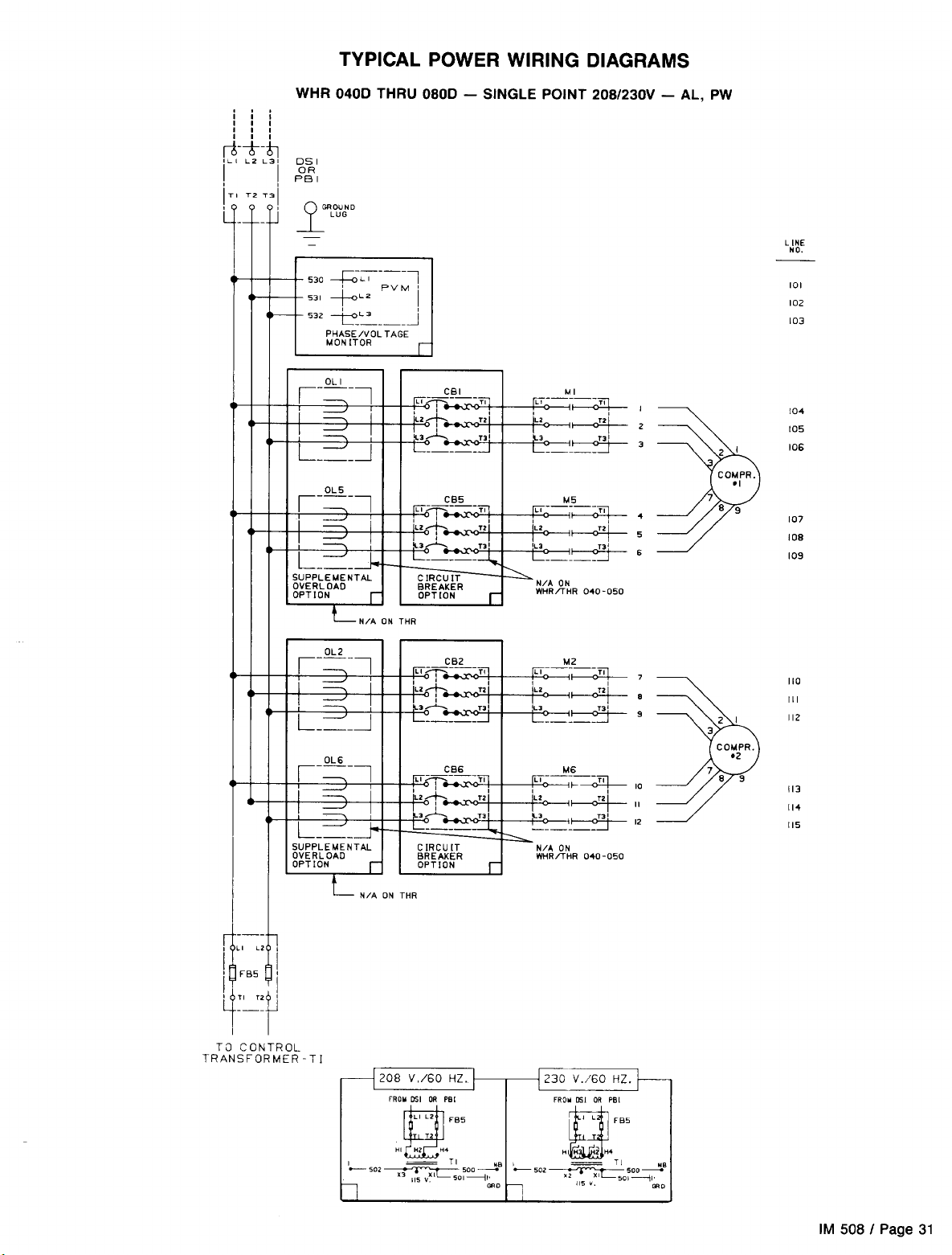
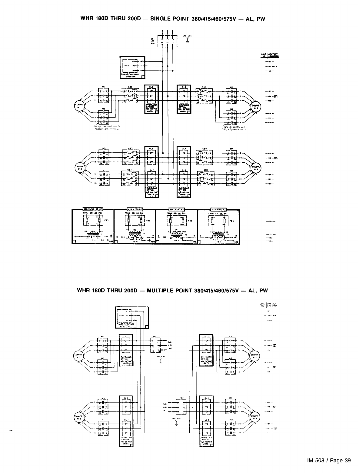
NOTES:
1. PBl and
2.
Pf32
Circuit breakers and overloads are provided as an option. The power panel
could contain one, both, or neither of these options.
are used with multiple point power wiring.
tional Electrical Code and/or local requirements.
An open fuse indicates a short, ground, or overload. Before
replacing a fuse or restarting a compressor or fan motor, the
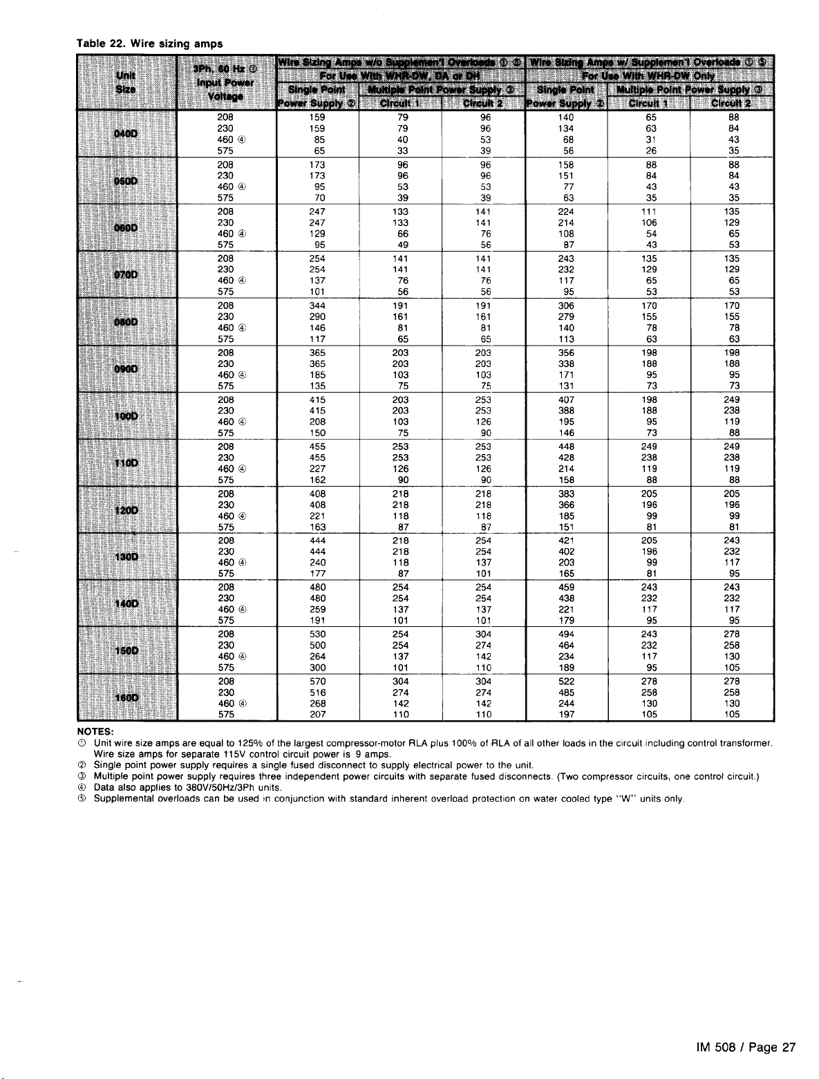
trouble must be found and corrected. Tables in the Electrical
Data section give specific information on recommended wire
sizes.
Unit power inlet wiring must enter the top of the control box
(right side) through a patch plate provided for field terminating
conduit. (Refer to control panel layout drawings for general
location of power inlet and components.)
WARNING: Use only copper conductors in main terminal
block. If the power input conductors are aluminum, use a compression splice to change to copper before terminating in
block.
TYPICAL CONTROL AND SAFETY WIRING DIAGRAMS
Refer to IM 493 for typical control and safety wiring or actual unit wiring diagrams.
CURRENT TRANSFORMER
The typical power wiring diagrams shown on pages 19 thru 35 include the current transformer
(CTI)
wiring shown in Figure 29. CT1 provides a O-4 vdc signal to the
MicroTech
panel which
is then converted to XXX% RLA.
IM 508 I Page 29
Page 30

Page 31
Page 32

Page 33

Page 34

Page 35

Page 36

Page 37

Page 38

Page 39
Page 40

Page 41

Page 42
STARTUP AND SHUTDOWN
This manual covers only the mechanical aspects of WHR chillers equipped with the
trol. All of the operating, safety control and installation requirements of the
Installation and Maintenance Bulletin 493, which must be consulted before startup and operation is attempted.
PRE STARTUP
1.
With main disconnect open, check all electrical connections in control panel and starter to be sure they are tight
and provide good electrical contact. Although connections are tightened at the factory, they may have
loosened enough in shipment to cause a malfunction.
2.
Check and inspect all water piping. Make sure flow direction is correct and piping is made to correct connection
on evaporator and condenser.
3.
Open all water flow valves to the condenser and
evaporator.
4.
Flush the cooling tower and system piping to be sure the
system is clean. Start evaporator pump and manually
start condenser pump and cooling tower. Check all pip-
ing for leaks. Vent the air from the evaporator and condenser water circuit as well as from the entire water
system. The cooler circuits should contain clean, noncorrosive water.
If water regulating valves are provided, connect their
5.
capillary to the manual valves provided on the condensers and open the manual valves.
Check to see that the water temperature thermostat sen-
6.
sor is installed in the entering water line to the chiller.
7.
Making sure control stop switch
Sl
is open (off) and
pumpdown
down,” throw the main power and control disconnect switches to “on.” This will energize crankcase heaters. Wait
a minimum of 12 hours before starting up unit.
Check compressor oil level. Prior to startup, the oil level
8.
should cover at least one-third of the oil sightglass.
Check pressure drop across evaporator and condenser,
9.
and see that water flow is correct per the design flow rates
and data on page 9.
Check the actual line voltage to the unit to make sure
10.
it is the same as called for on the compressor nameplate
within
exceed 2%. Verify that adequate power supply and
capacity is available to handle load.
Make sure all wiring and fuses are of the proper size. Also
11.
make sure all interlock wiring is completed per McQuay
diagrams.
Verify that all mechanical and electrical inspections by
12.
code authorities have been completed.
Make sure all auxiliary load and control equipment is
13.
operative and that an adequate cooling load is available
for initial startup.
MicroTech
rtlO% and that phase voltage unbalance does not
MicroTech
control are covered in the separate
switches PSl and PS2 are on “manual
reciprocating chiller con-
pump-
STARTUP
1.
Open the compressor suction and discharge shutoff valves
until
backseated. Always replace valve seal caps.
2.
Open the manual liquid line shutoff valve.
3.
Verify
crankcase heaters have operated for at least 12 hours
prior
to startup. Crankcase should be warm.
4.
After
running the unit for a short time, check the oil level
n each compressor crankcase, rotation of condenser fans
(if
any), and check for flashing in the refrigerant sight-
glass.
At this point it will be necessary to complete
1. Move the Circuit 1 and Circuit 2 switches to the “Pumpdown and Stop” position, causing each circuit to pump
down and stop. In this condition, the compressors will
main off and no additional
evaporator pressure rises above the low pressure control
cut-in setpoint.
Close the remote stop switch to enable the chiller. Move the the unit will stage as required. If the controller is not calling
Circuit
1
controller is calling for cooling, the compressors will start and there is a call for cooling.
and Circuit 2 switches to the Auto position. If the for cooling the compressors may pump down and stop until
pumpdown
STARTUP AFTER TEMPORARY SHUTDOWN
MicroTech
TEMPORARY SHUTDOWN
re-
will occur even if
pre-start checkout found in IM 493 before system operation is attempted. After
startup is complete be sure to complete the following
mechanical startup requirements.
5. After system performance has stabilized, it is necessary
that the “Compressorized Equipment Warranty Form”
(Form No. 206036A) be completed to obtain full warranty
benefits. Be sure to list the pressure drop across both
vessels. This form is shipped with the unit and after completion should be returned to the McQuayService Depart-
ment through your sales representative.
2. After both circuits have pumped down, open the remote
stop switch and the controller will stop the chilled water
pump.
MicroTech
pre-start checkout and
Page 42
I
IM 508
Page 43

EXTENDED SHUTDOWN
1.
Move the Circuit 1 and Circuit 2 switches to the “Pumpdown and Stop” position. After the compressors have shut
off, open the remote stop switch and the controller will stop
the chilled water pump.
2.
Move the system switch to the “Emergency Stop”
tion and turn off main power to the chiller and the chilled
water pumps.
STARTUP AFTER EXTENDED SHUTDOWN
1.
Inspect all equipment to see that it is in satisfactory At this point is will be necessary to complete
operating condition.
2.
Remove all debris that has collected on the surface of the
condenser coils (remote condenser models).
3.
Open the compressor suction and discharge valves until
backseated. Always replace valve seal caps.
4.
Open the manual liquid line shutoff valves.
5.
Allow the crankcase heaters to operate for at least 12 hours
prior to startup.
posi-
3. Close the manual liquid line shutoff valves.
4. Close the compressor suction and discharge service valves
and oil equalization valves on four compressor units.
5. Tag all opened electrical disconnect switches to warn
against startup before opening the compressor
discharge and liquid line service valves.
pre-start checkout found in
iion is attempted. After
startup is complete be sure to complete the following
mechanical startup requirements.
8
After running the unit for a short time, check the oil level
in each copressor crankcase and for flashing in the
refrigerant sightglass (see Maintenance section).
IM
493 before system
MicroTech
pre-start checkout and
sucton,
MicroTech
opera-
SYSTEM MAINTENANCE
GENERAL
To assure smooth operation at peak capacity and to avoid
damage to package components, a program of periodic inspections should be set up and followed. The following items
are intended as a guide to be used during inspection and must
be combined with sound refrigeration and electrical practices
to assure trouble-free performance.
The liquid line sightglass/moisture indicator on all circuits
must be checked to be sure the glass is full and clear and
the moisture indicator indicates a dry condition. If the indicator
shows that a wet condition exists or if bubbles show in the
glass, even with a full refrigerant charge, the filter-drier element must be changed.
Water supplies in some areas may tend to foul the water
cooled condenser to the point where cleaning is necessary.
The fouled condenser will be indicated by an abnormally high
condensing pressure and may result in nuisance tripouts. To
clean the condenser, a chemical descaling solution should
be used according to the manufacturer’s directions.
Systems with remote air cooled condensers require periodic
cleaning of the finned surface of the condenser coil. Cleaning
CONTROL CENTER ELECTRICAL SERVICE
The electrical control center is relativelv easv to service since
indicator lights are provided to show unit status. Determine
that the problem is actually in the control panel before
proceeding.
By referring to the schematic wiring diagrams, the trouble
can be isolated to a particular section of the panel.
WARNING: Warranty is voided if wiring is not in accordance
with specifications. A blown fuse or tripped protector indicates
a short ground or overload. Before replacing fuse or restarting compressor, the trouble must be found and corrected.
It is important to have a qualified control panel electrician service this panel. Unqualified tampering with the controls can
cause serious damage to equipment and void the warranty.
The following steps should be taken prior to attempting any
ing may be accomplished by using a cold water spray,
brushing, vacuuming, or high pressure air. No tools should
be used that could damage the coil tubes or fins.
A lead-lag switch is provided on all multiple compressor
models to permit even distribution of wear on the compressors. This switch should be turned on on an annual basis.
The compressor oil level must be checked periodically to
be sure the level is at the center of the oil sightglass. Low
oil level may cause inadequate lubrication and oil failure
switch tripout. If the oil level is low and oil must be added,
use oils referred to in “Compressor Oil Level” section below.
A pressure tap has been provided on the liquid line
downstream of the filter-drier and solenoid valve but before
the expansion valve. An accurate subcooled liquid pressure
and temperature can be taken here. The pressure read here
could also provide an indication of excessive pressure drop
through the filter-drier and solenoid valve due to a clogging
filter-drier.
NOTE: A normal pressure drop through the solenoid valve
is approximately 3 psig at full load conditions.
service on the control center:
1.
Study the wiring diagram so that you understand the operation of the SEASONPAK water chiller.
2.
Before investigating trouble in the control center, check for
burned out light bulbs by testing across the appropriate
terminals.
CAUTION: The panel is always energized to ground
even though the system switch is off. If it is necessary to
de-energize the complete panel including crankcase
heaters, pull main disconnect.
If motor or compressor damage is suspected, do not restart
until a qualified serviceman has checked the unit.
IM 508 I Page 43
Page 44
ELECTRICAL TERMINALS
CAUTION: Electric shock hazard. Turn off all power before continuing with following service.
All power electrical terminals should be retightened every six months, as they tend to loosen
in service due to normal heating and cooling of the wire.
OPERATING LIMITS
0 Maximum allowable condenser water pressure is 250 psig.
0 Maximum allowable cooler water pressure is 225 psig.
0 Maximum leaving condenser water temperature is
135” F.
0 Minimum leaving water temperature from the cooler with-
This corresponds to 340 to 350 psig head pressure.
0 Maximum allowable water temperature to cooler in a
operating cycle is 105°F. Maximum entering water
temper-
non-
0
COMPRESSOR OIL LEVEL
The oil level should be watched carefully upon initial startup
than keeping the oil clean and dry.
and for sometime thereafter.
At the present time, Suniso No.
3GS,
Calumet
R015,
and
Texaco WF32 oils are approved by Copeland for use in these
compressors. The oil level should be maintained at about
onethird of the sightglass on the compressor body but is acceptable at any height on the sightglass.
Oil may be added to the
Copeland
compressor through the
oil fill hole in the crankcase. To add oil, isolate the crankcase
and pour or pump in the necessary oil. If the system contains
no refrigerant, no special precautions are necessary other
tion valve and reduce crankcase pressure to 1 to 2 psig. Stop
the compressor and close the discharge valve.
pressor is exposed to the atmosphere, the refrigerant will
generate a vapor pressure, retarding the entrance of contaminants. Before resealing the compressor, purge the crankcase by opening the suction valve slightly for 1 or 2 seconds.
Close the oil port, open the compressor valves and restore
the system to operation.
ature for operating cycle is 90°F (during system
change-
over from heating to cooling cycle).
out freeze protection is 42°F.
Minimum entering tower condenser water temperature is
70°F.
If the system contains a refrigerant charge, close the suc-
Add the required amount of oil. During the period the com-
OIL EQUALIZATION
Some larger models with four compressors (WHR-180 thru
240D) come equipped with oil equalization lines connecting
the crankcase of both compressors in each refrigerant circuit.
This allows the oil to move from one compressor crankcase
to the other during normal operation, and balance between
the two when the compressors are off. This method of equali-
zation prohibits the oil level from dropping below the bottom
level of the sightglass. Some difference in crankcase oil levels
will still exist during unit operation due to compressor internal
REFRIGERANT SIGHTGLASS AND MOISTURE INDICATOR
The refrigerant sightglasses should be observed period-
ically. (A monthly observation should be adequate.) A clear
glass of liquid indicates that there is adequate refrigerant
charge in the system to insure proper feed through the
pansion
valve. Bubbling refrigerant in the sightglass indicates
ex-
that the system is short of refrigerant charge. Refrigerant gas
flashing in the sightglass could also indicate an excessive
CRANKCASE HEATERS
The compressors are equipped with crankcase heaters. The
20 HP and larger model compressors have heaters inserted
into the crankcase. The function of the heater is to keep the
temperature in the crankcase high enough to prevent refrig-
erant from migrating to the crankcase and condensing in the
oil during off-cycle.
When a system is to be started up initially in cold ambient,
the power to the heaters should be turned on for some time
pressures.
The oil equalization line contains a manual shutoff valve
for isolating a compressor during service work. The ball valves
are shipped in the closed position with a tag attached stating
“Notice, Valve Shipped In Closed Position. Can Be Open For
Normal Operation.” When valves are closed for compressor
service, make sure they are opened again for unit operation.
For water cooled units, operation with oil equalization lines
closed should be satisfactory for most jobs.
pressure drop in the line, possibly due to a clogged filter-drier
or a restriction elsewhere in the system. An element inside
the sightglass indicates what moisture condition corresponds
to a given element color. If the sightglass does not indicate
a dry condition after about 12 hours of operation, the unit
should be pumped down and the filter-driers changed.
(at least 12 hours) before the compressor is started. The
crankcase should be up to about 80°F before the system is
started up, to minimize lubrication problems on liquid slugging of compressor on startup.
If the crankcase is cool (below 80°F) and the oil level in
the sightglass is FULL to top, allow more time for oil to warm
before starting the compressor.
Page 44
I
IM 508
Page 45

SYSTEM SERVICE
NOTE: Service on this equipment is to be performed by qualified refrigeration personnel. Causes for repeated tripping of safety
controls must be investigated and corrected. CAUTION: Disconnect all power before doing any service inside the unit.
FILTER-DRIERS
To change the filter-drier, pump each refrigerant circuit down
by closing the manual liquid line shutoff valve while a com-
pressor is running. After both refrigerant circuits are pumped
down, move the system switch to the “Emergency Stop” posi-
tion. This will remove all liquid refrigerant from the evaporator
and section of liquid line up to the shutoff valve. Only a small
amount of vapor will remain in the liquid line/filter-drier section. Front seat the compressor suction valve(s), Remove and
replace the filter-drier(s). Evacuate the lines through the liquid line manual shutoff valves to remove non-condensables
that may have entered during filter replacement. A leak check
is recommended before returning the unit to operation.
LIQUID LINE SOLENOID VALVE
The liquid line solenoid valves, which are responsible for
automatic
pumpdown
during normal unit operation, do not
normally require any maintenance. However, in the event of
failure they may require replacement of the solenoid coil or
of the entire valve assembly.
The solenoid coil may be removed from the valve body
without opening the refrigerant piping by moving Circuit 1 and
Circuit 2 switches to the “Pumpdown and Stop” position.
NOTE: On Arrangement A units, the filter-drier cores are shipped in the unit
control box and are to be Installed prior to evacuating and charging the unit.
The coil can then be removed from the valve body by simply
removing a nut or snap-ring located at the top of the coil. The
coil can then be slipped off its mounting stud for replacement.
Be sure to replace the coil on its mounting stud before
return-
ing the unit to operation.
To replace the entire solenoid valve, follow the steps involved when changing a filter-drier.
THERMOSTATIC EXPANSION VALVE
The expansion valve is responsible for allowing the proper
amount of refrigerant to enter the evaporator regardless of
cooling load. It does this by maintaining a constant superheat.
(Superheat is the difference between refrigerant temperature
as it leaves the evaporator and the saturation temperature corresponding to the evaporator pressure.) All WHR chillers are
factory set for between
8°F
and
12°F
superheat at full load.
If it is necessary to increase the superheat setting of the valve,
remove the cap at the bottom of the valve to expose the ad-
justment screw. Turn the screw clockwise (when viewed from
the adjustment screw end) to increase the superheat and
counterclockwise to reduce superheat. Allow time for system
rebalance after each superheat adjustment.
The expansion valve, like the solenoid valve, should not normally require replacement, but if it does, the unit must be
pumped down by following the steps involved when changing a filter-drier.
If the problem can be traced to the power element only,
it can be unscrewed from the valve body without removing
the valve, but only after pumping the unit down.
WARNING: Adjustment of expansion valve should only be
performed by a qualified service technician.
EVAPORATOR
The evaporator is of the direct expansion, shell-and-tube type
with refrigerant flowing through the tubes and water flowing
through the shell over the tubes. The tubes are internally
finned to provide extended surface as well as turbulent flow
of refrigerant through the tubes. Normally no service work is
required on the evaporator. There may be instances where
a tube will leak refrigerant into the water side of the system.
In the cases where only one or two tubes leak, the problem
can best be solved by plugging the tube at both ends. When
the tube must be replaced, the old tube can be removed and
replaced.
To remove a tube, the unit should be temporarily pumped
Figure
30.
,.._.,
Inlet
WIII
NOTE: Superheat
imately as follows- between 6°F and 12°F at full load; between 6°F and 10°F
at part load.
vary with compressor unloading, but should be approx-
Power Element
(Contains Diaphragm)
Adjustment Screw
down. Follow the steps involved when changing a filter-drier.
These steps will insure a minimum amount of refrigerant loss
when the evaporator is opened up. The tubes are mechanical-
ly expanded into the tube sheets (see Figure 31) at each end
of the cooler. In order to remove the tubes, it is necessary
to break this bond by collapsing the tube. After doing this at
both ends of the shell, the tube can be removed for replacement. The new tube can then be inserted and re-expanded
into the tube sheet.
NOTE: The bond produced by expansion must be refrig-
erant tight. This bond must be produced by applying Locktite
(red) to the
fube
and rolling it into the
fube
sheet.
IM 508 I Page 45
Page 46

After re-assembling the evaporator, a small amount of
refrigerant should be introduced by momentarily opening the
manual liquid line valve. A leak check should then be
per-
formed on the evaporator.
Tube removal can only take place after the leaking tube is
located. One method that would work would be to subject each
tube to
air pressure by plugging each end and, with a pressure
Figure
31. Top View of Typical Dual Circuit Shell-and-Tube Evaporator
Liquid Connections
Suction Connections
WATER COOLED CONDENSER
The condenser is of the shell-and-tube type with water
flow-
gauge attached to one of the end plugs, observing if there
is a loss of air pressure over a period of a minute or two.
Another method is to place a cork plug in each tube on both
ends of the cooler and applying pressure to the shell of the
cooler. After a period of time, the pressure will leak from the
shell into the leaking tube or tubes and pop out the cork plug.
Water Baffles
L
Refrigerant Tubes
Shell
Water Nozzles
ment W units. Heat recovery units have integral subcoolers
ing through the tubes and refrigerant in the shell. External in the tower condensers. All condensers are equipped with
finned copper tubes are rolled into steel tube sheets. Integral 450 psig relief valves. Heat recovery condensers are freesubcoolers are incorporated on 40 ton and larger Arrange- draining to the lower (tower) condensers and do not subcool.
HOT GAS BYPASS (OPTIONAL)
This option allows passage of discharge gas to the evaporator
permitting operation at lower loads than available with compressor unloading. It also keeps the velocity of refrigerant gas
high enough for proper oil return at light load conditions. A
solenoid valve in the hot gas bypass line is wired in parallel
with the compressor unloader
Ul.
Thus, the hot gas solenoid
cannot open unless the compressor is operating in an unloaded mode. If only one hot gas valve is specified for the
unit, the hot gas bypass is wired in the first refrigerant circuit
and the lead-lag switches are therefore eliminated. The hot
gas bypass option is also available for the second refrigerant
circuit whereby the lead-lag switches remain.
The pressure regulating valve is factory set to begin open-
ing at 58 psig (32°F for R-22). This setting can be changed
Figure 32.
Hot Gas Bypass Piping Diagram
f
I
I
b,
TL”
by changing the pressure of the air charge in the adjustable
bulb. To raise the pressure setting, remove the cap on the
bulb and turn the adjustment screw clockwise. To lower the
setting, turn the screw counterclockwise. Do not force the adjustment beyond the range it is designed for, as this will
damage the adjustment assembly.
The regulating valve opening point can be determined by
slowly reducing the system load while observing the suction
pressure. When the bypass valve starts to open, the refrigerant
line on the evaporator side of the valve will begin to feel warm
to the touch.
CAUTION: The hot gas line may become hot enough to
cause injury in a very short time; care should be taken during valve checkout.
Figure 33. Hot Gas Bypass Adjustment Range
Page 46 I IM 508
30
40
50
TEMPERATURE
60
70
(“F)
80
AT BULB LOCATION
90
100
110
Page 47

IN-WARRANTY RETURN MATERIAL PROCEDURE
COMPRESSOR
Copeland
who maintain a stock of replacement compressors and service parts to serve refrigeration contractors and servicemen.
sales representative, or Warranty Claims Department at the
address on the cover of this bulletin. You will be authorized
to exchange the defective compressor at a Copeland wholesaler, or an advance replacement can be obtained. A credit
is issued you by the wholesaler for the returned compressor
after Copeland factory inspection of the inoperative compressor. If that compressor is out of Copeland’s warranty, a
salvage credit only is allowed. Provide full details; i.e., unit
Material may not be returned except by permission of authoriz-
ed factory service personnel at Minneapolis, Minnesota. A
“return goods” tag will be sent to be included with the returned
material. Enter the information as called for on the tag in order
to expedite handling at our factories and prompt issuance of
credits.
replacement. Therefore, a purchase order must be entered
through your nearest McQuay representative. The order
Refrigeration Corporation has stocking wholesalers
When a compressor fails in warranty, contact your local
COMPONENTS OTHER THAN COMPRESSORS
The return of the part does not constitute an order for
model and unit serial numbers. Include the invoice and the
salvage value credit memo copies and we will reimburse the
difference. In this transaction, be certain that the compressor
is definitely defective. If a compressor is received from the
field that tests satisfactorily, a service charge plus a transportation charge will be charged against its original credit value.
On all out-of-warranty compressor failures,
the same field facilities for service and/or replacement as
described above. The credit issued by Copeland on the returned compressor will be determined by the repair charge
established for that particular unit.
should include part name, part number, model number and
serial number of the unit involved.
Following our personal inspection of the returned part, and
if it is determined that the failure is due to faulty material or
workmanship, and in warranty, credit will be issued on
customer’s purchase order.
All parts shall be returned to the pre-designated factory,
transportation charges prepaid.
Copeland
offers
IM 508
I
Page 47
Page 48

TROUBLESHOOTING CHART
Compressor Will
Not Run
Compressor Noisy
or Vibrating
High Discharge
Pressure
Low Discharge
Pressure
High Suction
Pressure
Low Suction
Pressure
Little or No Oil
Pressure
Compressor
Loses
Oil
Motor Overload
Relays or Circuit
Breakers Open
Compressor Thermal
Protector Switch Open
Freeze Protection
Opens
1.
Main switch, circuit breakers open.
2.
Fuse blown.
3.
Thermal overloads tripped or fuses blown
4.
Defective contactor or coil.
5.
System shut down by safety devices.
6.
No cooling requrred.
7.
Liquid line solenoid will not open.
6.
Motor electrical trouble.
9.
Loose
wmng.
1. Flooding of refrigerant into crankcase.
2. Improper piping support on suction or liquid line.
3. Worn compressor.
1. Condenser water insufficient or temperature too high
2. Fouled condenser tubes (water cooled condenser). Clogged spray
nozzles (evaporative condenser). Dirty tube and fin surface (air
cooled condenser).
3. Noncondensables in system.
‘4. System overcharged with refrigerant.
5. Discharge shutoff valve partially closed.
‘6. Condenser undersized.
‘7. High ambient conditions.
1.
Fault condenser temperature regulation.
2. Suction shutoff valve partially closed.
3. Insufficient refrigerant in system.
4. Low suction pressure.
5. Compressor operating unloaded.
‘6. Condenser too large.
‘7. Low ambient conditions.
1. Excessive load.
2. Expansion valve overfeeding.
3. Compressor unloaders open.
1.
Lack of refrigerant.
2.
Evaporator dirty.
3.
Clogged liquid line filter-drier.
4.
Clogged suction line or compressor suction gas strainers.
5.
Expansion valve malfunctioning.
Gasket failure in evaporator head ring.
6.
7.
Condensing temperature too low.
Compressor will not unload.
0.
9. Insufficient water flow.
1.
Clogged suction oil strarner.
2. Excessive liquid in crankcase.
3. Oil pressure gauge defective.
4. Low oil pressure safety switch defective.
5. Worn oil pump.
6. Oil pump reversing gear stuck in wrong position
7. Low oil level.
6.
Loose fitting on oil lines.
9. Pump housing gasket leaks.
10. Flooding of refrigerant into crankcase.
1. Lack of refrigerant.
‘2. Velocity in risers too low.
‘3. Oil trapped in line.
4. Excessive compression ring blow-by.
1. Low voltage during high load conditions.
2. Defective or grounded wiring
3. Loose power wiring.
4. High condensing temperature.
5. Power line fault causing unbalanced voltage.
6. High ambient temperature around the overload relay.
7. Failure of second starter to pull in on part
start system.
1. Operating beyond design
2. Discharge valve partially shut.
3. Blown valve plate gasket.
1.
Thermostat set too low.
2. Low water flow.
3. Low suction oressure.
m
motor or power circuits.
conditrons.
windmg
1. Close switch.
2. Check electrical circuits and motor winding for shorts or grounds.
Investigate for
breakers after fault is corrected.
3. Overloads are auto reset. Check unit closely when unit comes
back on line.
4. Repair or replace.
5. Determine type and cause of shutdown and correct it before reset-
ting safety switch.
6. None. Wait until unit calls for cooling.
7. Repair or replace coil.
6. Check motor for opens, short circuit, or burnout.
9. Check all wire junctions. Tighten all terminal screws.
1.
Check superheat setting of expansion valve.
2. Relocate, add or remove hangers
3. Replace.
1.
Readjust temperature control or water regulating valve. Investigate
ways to increase water supply
2. Clean.
3. Purge the noncondensabies.
4. Remove excess refrigerant.
5. Open valve.
6. Check condenser rating tables against the operation.
7. Check condenser rating tables against the operation.
1. Check condenser control operation.
2. Open valve.
3. Check for leaks. Repair and add charge.
4. See corrective steps for low suction pressure below.
5. See corrective steps for failure of compressor to load.
6. Check condenser rating table against the operation.
7. Check condenser rating tables against the operation.
1. Reduce
2. Check remote bulb. Regulate superheat.
3. See corrective steps
1. Check for leaks. Reoarr and add charoe.
2. Clean chemically.
3.
Replace cartridge(s).
4. Clean strainers.
5. Check and reset for proper superheat. Replace if necessary.
6. Check
7. Check means for regulating condensing temperature.
6. See
9. Adjust gpm.
1. Clean.
2. Check crankcase heater. Reset expansion valve for higher
superheat. Check liquid line solenoid valve operation.
3. Repair or replace. Keep valve closed except when taking reading.
4. Replace.
5. Replace.
6. Reverse direction of compressor rotation by switching compressor
leads.
7. Add oil.
6. Check and tighten system.
9. Replace gasket.
10. Adjust thermal expansion valve.
TCheck
2. Check riser sizes.
3. Check pitch of lines and refrigerant velocities.
4. Replace compressor.
1. Check supply voltage for excessive line drop.
2. Replace compressor-motor.
3. Check all connections and tighten.
4. See corrective steps for high discharge pressure.
5. Check supply voltage. Notify power company. Do not start until
fault
6. Provide ventilation to reduce heat.
7. Repair or replace starter or time delay mechanism.
1. Add facilities so that conditions are
2. Open valve
3. Replace gasket.
1 Reset to
2. Adjust gpm.
3. See “Low Suction Pressure
posstble overloading. Replace fuse or reset
loador
add additional equipment.
foffailure
of compressor to load.
”
”
withrn allowable
Irmrts.
’
fIP
across evaporator.
corrrective steps for failure of compressor to unload.
for leaks and repair Add refrigerant.
IS corrected
42’F
or above.
Page 48 I IM 508
*
Remote Condenser Models.
NOTE: FOR TROUBLESHOOTING PROCEDURES ON MICROTECH CONTROL REFER TO IM 493.
Page 49

PRODUCT WARRANTY
SnyderGeneral Corporation, hereinafter referred to as the
“Company,” warrants that it will provide, at the Company’s
option, either free replacement parts or free repair of component parts in the event any product manufactured by the
Company and used
material or workmanship within twelve (12) months from initial startup or eighteen (18) months from the date shipped
by the Company, whichever comes first. For additional consideration, the Company warrants that for four (4) years following the initial warranty period it will provide, at the Company’s
option, free replacement parts for the motor-compressor, or,
free replacement for any integral component of the
compressor which proves defective in material or workmanship. For an additional consideration, the Company warrants
that for nine (9) years following the initial warranty period it
will provide free replacement of the heat exchanger in
fired or oil-fired furnaces which proves defective in material
and workmanship. (Extended warranties for motor-compressors and heat exchangers are not applicable unless separately
purchased.)
To obtain assistance under this parts warranty, extended
motor-compressor warranty, or extended heat exchanger warranty, simply contact the selling agency. To obtain informa-
tion or to gain factory help: For brandnames Arcoaire and/or
Comfortmaker contact SnyderGeneral Corporation, Warranty Department, 302 Nichols Drive, Hutchins, TX 75141,
telephone (214) 2257351. For McQuay, Climate Control, Barry
Blower and
Corporation, Warranty Claims Department,
Minneapolis, MN 55440, telephone (612)
THIS WARRANTY CONSTITUTES THE BUYER’S SOLE
REMEDY. IT IS GIVEN IN LIEU OF ALL OTHER WARRAN-
in the United States proves defective
JennFan
brandnames, contact SnyderGeneral
553-5330.
motor-
P.
0. Box 1551,
in
gas-
TIES. THERE IS NO IMPLIED WARRANTY OF MERCHANTABILITY OR FITNESS FOR A PARTICULAR PURPOSE.
IN NO EVENT AND UNDER NO CIRCUMSTANCES SHALL
THE COMPANY BE LIABLE FOR INCIDENTAL OR CONSEQUENTIAL DAMAGES, WHETHER THE THEORY BE
BREACH OF THIS OR ANY OTHER WARRANTY, NEGLIGENCE OR STRICT TORT.
This parts warranty and the optional extended warranties
extend only to the original user. Of course, abuse, misuse,
or alteration of the product in any manner voids the Company’s warranty obligation. Neither the parts or extended war-
ranty obligates the Company to pay any labor or service costs
for removing or replacing parts, or any shipping charges.
Refrigerants, fluids, oils, and expendable items such as filters
are not covered by this warranty.
The extended warranties apply only to integral components
of the motor-compressor or heat exchanger, not to refrigerant
controls, electrical controls, or mechanical controls, or to
failures caused by failure of those controls.
Attached to this warranty is a requirement for equipment
containing motor-compressors and/or furnaces to report start-
up information. The registration form accompanying the product must be completed and returned to the Company within
ten (10) days of original equipment start-up. If that is not done.
the date of shipment shall be presumed to be the date of start-
up and the warranty shall expire twelve (12) months from that
date.
No person (including any agent, salesman, dealer or
distributor) has authority to expand the Company’s obligation
beyond the terms of this express warranty, or to state that the
performance of the product is other than that published by
the Company.
IM 508
I Page 49
 Loading...