

Page 1
Installation, Operation and Maintenance Manual IOMM WHR
Group: Chiller
Part Number: 330227701
Effective: June 2001
Supercedes: IM 224-5
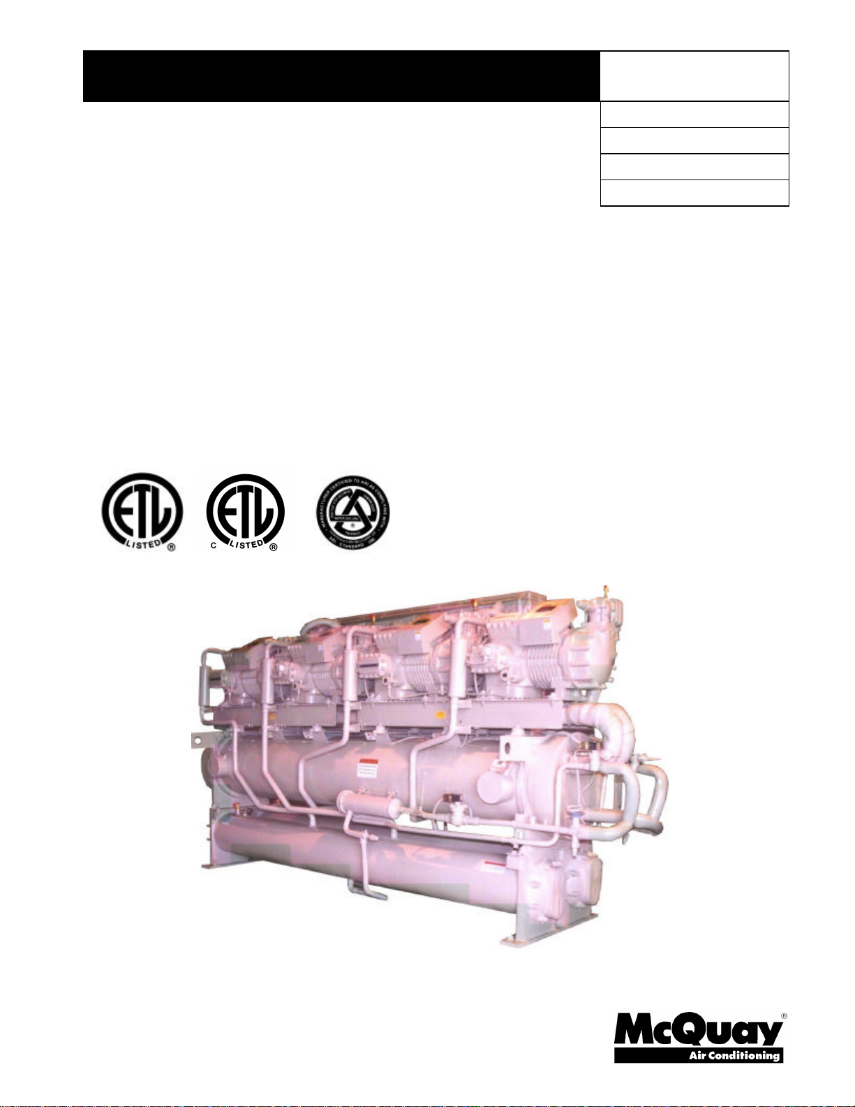
Reciprocating Chillers
WHR 100FW to WHR 180FW, Packaged Water-Cooled
WHR 100FA to WHR 180FA, Remote Condenser
100 to 180 Tons, 350 to 630 kW
R-22, R134a
60 Hz
Page 2

Table of Contents
Our facility is ISO Certified
Introduction..............................................3
General Description.................................................3
Nomenclature............................................................3
Inspection.................................................................3
Installation...............................................4
Handling....................................................................4
Moving the Unit.......................................................4
Location.....................................................................5
Space Requirements for Connections and
Servicing................................................................5
Placing the Unit........................................................5
Vibration Isolators....................................................6
Water Piping.............................................8
General.......................................................................8
Chilled Water Piping................................................9
Chilled Water Thermostat.....................................10
Flow Switch.............................................................10
Glycol Solutions.....................................................11
Condenser Water Piping.......................................12
Head Pressure Control, Tower System...............13
Head Pressure Control, Well Water System .......13
Water Pressure Drop.............................................14
Refrigerant Piping .................................16
Unit with Remote Condenser...............................16
Unit with Factory Mounted Condensers ...........19
Dimensional Data..................................20
Physical Data.........................................24
FW Water-Cooled..................................................24
FA Remote Condenser..........................................26
Wiring.....................................................29
Sequence of Operation..........................31
Electrical Data.......................................33
Control Center Layout, WHR 100F through
WHR 180F............................................................37
Start-Up and Shutdown..........................39
Pre Start-up.............................................................39
Start-up ....................................................................39
Weekend or Temporary Shutdown......................40
Start-up after Temporary Shutdown....................40
Extended Shutdown...............................................40
Start-up after Extended Shutdown.......................41
System Maintenance ............................42
General.....................................................................42
Control Center Service...........................................42
Electrical Terminals.................................................43
Operating Limits .....................................................43
Compressor Oil Level .............................................43
Oil Equalization.......................................................44
Refrigerant Sightglass and Moisture Indicator.44
Lead-Lag..................................................................44
Crankcase Heaters..................................................44
System Service......................................45
Filter-Driers..............................................................45
Liquid Line Solenoid Valve...................................45
Thermostatic Expansion Valve.............................46
Evaporator...............................................................47
Water Cooled Condenser......................................47
Standard Controls .................................48
Thermostat..............................................................48
Control Band...........................................................48
Oil Pressure Protection Control ............................49
Compressor Lockout..............................................50
High Pressure Control...........................................50
Low Pressure Control............................................51
Freezestat.................................................................51
Compressor Motor Protector ................................51
Optional Controls..................................52
Part Winding Start..................................................52
Low Ambient Start Timer (optional)....................52
Phase/Voltage Monitor (Optional).......................53
Alarm Bell (Optional).............................................53
High Return Water Control (Optional)................53
Hot Gas Bypass (Optional)...................................54
Controls, Settings and Functions..........55
Troubleshooting Chart ..........................57
2 WHR 100F through 180F IOMM WHR
"McQuay" is a registered trademark of McQuay International
"Illustrations and data cover McQuay International products at the time of publication and we reserve the right
to make changes in design and construction at anytime without notice".
2001 McQuay International
Page 3
Introduction
General Description
McQuay Type WHR water chillers are designed for indoor installations and are compatible with either
air or water as a condensing medium. Each unit is completely assembled and factory wired before
evacuation, charging and testing. Each unit consists of accessible hermetic compressor(s),
replaceable tube shell-and-tube evaporator, water-cooled condenser (Model FW only), and complete
or partial refrigerant piping depending on the condensing medium.
Liquid line components that are included are manual liquid line shutoff valves, charging valves, filterdriers, liquid line solenoid valves, sightglass/moisture indicators, and balance port type thermal
expansion valves. Other features include compressor crankcase heaters, limited pumpdown during
“on” or “off” seasons, compressor lead-lag switch to alternate the compressor starting sequence, and
sequenced starting of compressors.
The electrical control center includes all equipment protection and operating controls necessary for
dependable automatic operation.
Compressor(s) are not fused, but can be protected by optional circuit breakers, or can rely on the field
installed fused disconnect for protection.
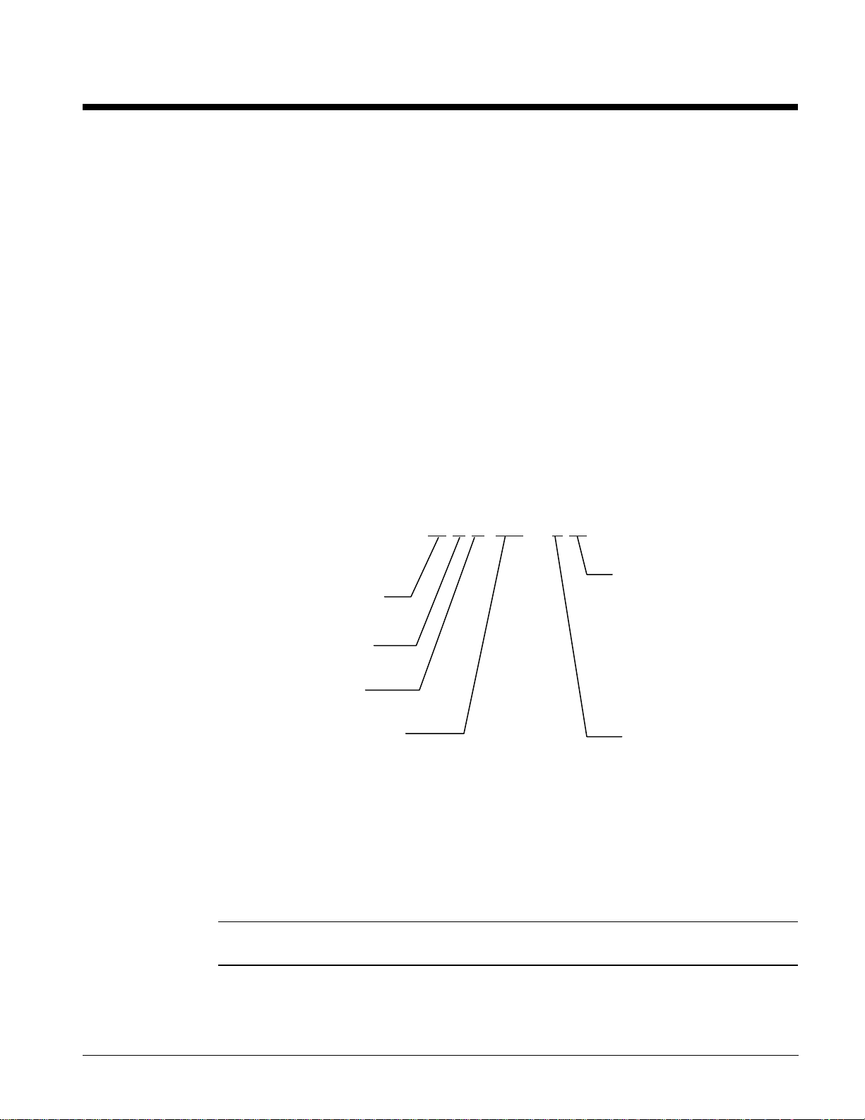
Nomenclature
W H R 100 - F W
Water Cooled
Condensing
Hermetic
Reciprocating
Nominal Capacity (Tons) Design Vintage
W = Single Water Cooled
Condenser per Refrigerant
Circuit
A = Unit Less Condensers
Inspection
When the equipment is received, all items should be carefully checked against the bill of lading to
provide a complete shipment. All units must be carefully inspected for damage upon arrival. All
shipping damage must be reported to the carrier and a claim must be filed with the carrier. The unit
serial plate should be checked before unloading the unit to be sure that it agrees with the power
supply available. Physical damage to unit after acceptance is not the responsibility of McQuay.
Note: Unit shipping and operating weights are given in the physical data tables beginning on
page 24.
IOMM WHR WHR 100F through 180F 3
Page 4
Installation
Note: Installation and maintenance are to be performed only by qualified personnel who are
familiar with local codes and regulations, and experienced with this type of equipment.
CAUTION
Avoid contact with sharp edges. Personal injury can result.
Handling
Every model WHR water chiller with water-cooled condensers is shipped with a full refrigerant charge
For shipment the charge is contained in the condenser and is isolated by the manual condenser liquid
valve and the compressor discharge service valve.
A holding charge is supplied in remote condenser models. The operating charge must be field
supplied and charged.
If the unit has been damaged, allowing the refrigerant to escape, there can be danger of suffocation in
the equipment area since the refrigerant will displace the air. Be sure to review Environmental
Protection Agency (EPA) requirements if damage has occurred. Avoid exposing an open flame to the
refrigerant.
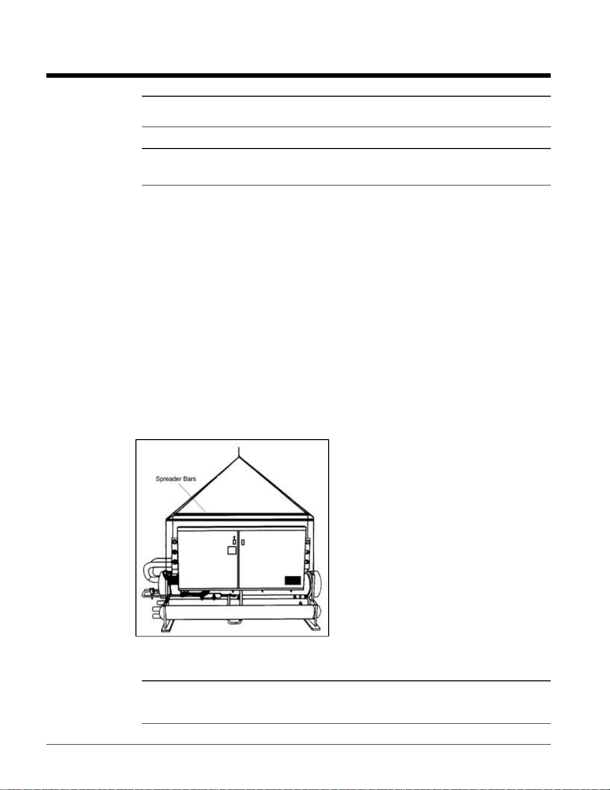
Moving the Unit
The McQuay water chiller is mounted on heavy wooden skids to protect the unit from accidental
damage and to permit easy handling and moving.
Figure 1, Moving the Unit
It is recommended that all moving and handling be
performed with the skids under the unit when
possible and that the skids not be removed until the
unit is in the final location. When moving the unit,
dollies or simple rollers can be used under the skids.
Never put the weight of the unit against the control
box.
In moving, always apply pressure to the base on the
skids only and not to the piping or shells. A long bar
will help move the unit easily. Avoid dropping the
unit at the end of the roll.
If the unit must be hoisted, it is necessary to lift the
unit by attaching cables or chains at the lifting holes
in the evaporator tube sheets. Spreader bars must be
used to protect the control cabinet and other areas of
the chiller (see Figure 1).
Do not attach slings to piping or equipment. Move unit in the upright horizontal position at all times.
Set unit down gently when lowering from the trucks or rollers.
Note: There will be extension brackets attached to the evaporator tube sheets on units
ordered with the optional acoustical enclosure. These brackets will be used for hoisting the
unit and should be removed when unit is in place.
4 WHR 100F through 180F IOMM WHR
Page 5
Location
Unit is designed for indoor application and must be located in an area where the surrounding ambient
temperatures are 40°F (4°C) above. A good rule of thumb is to place units where ambient
temperatures are at least 5°F (3°C) above the leaving water temperature.
Because of the electrical control devices, the units should not be exposed to the weather. A plastic
cover over the control box is supplied as temporary protection during shipment. A reasonably level
and sufficiently strong floor is all that is required for the water chiller. If necessary, additional
structural members should be provided to transfer the weight of the unit to the nearest beams.
Note: Unit shipping and operating weights are available in the physical data tables beginning
on page 24.
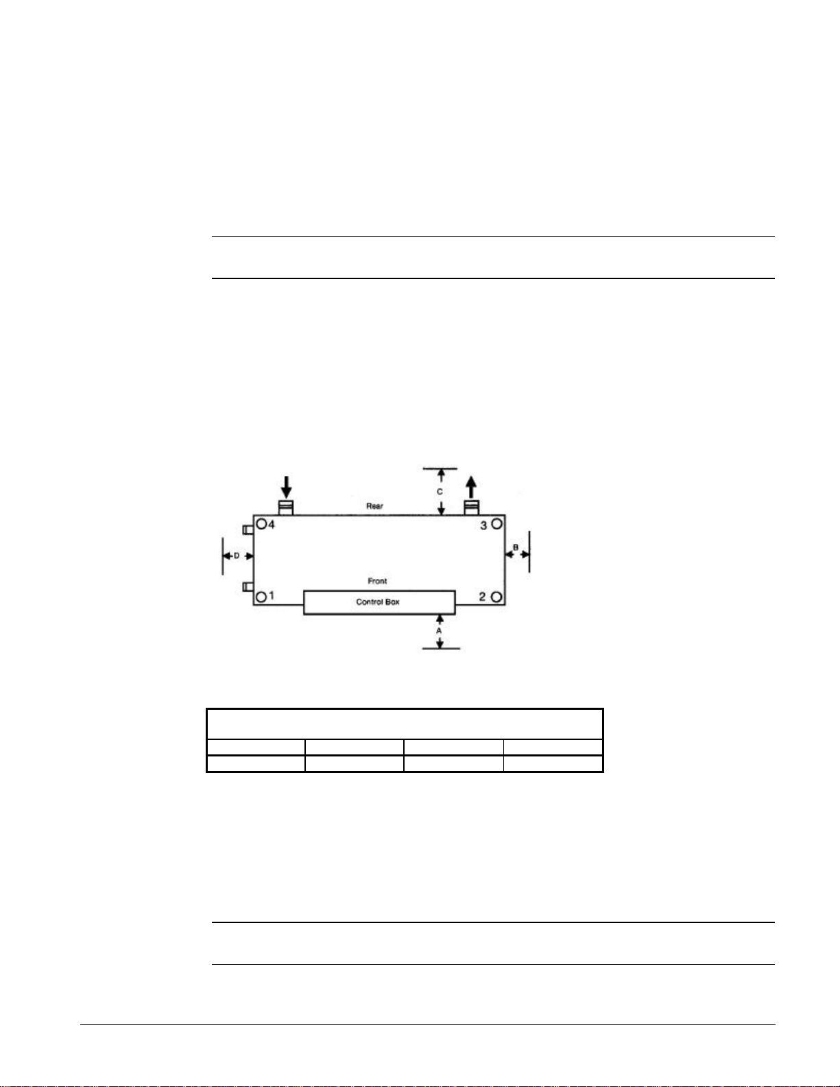
Space Requirements for Connections and Servicing
The chilled water piping for all units enters and leaves the cooler from the rear, with the control box
side being the front side of the unit. A clearance of 3 to 4 feet (914 to 1219mm) should be provided for
this piping and for replacing the filter-driers, for servicing the solenoid valves, or for changing the
compressors, if it ever becomes necessary.
Figure 2, Clearance Requirements
The condenser water piping enters and
leaves the shell from the one end. Work
space must be provided for water
regulating valves and for general
servicing. Clearance should be
provided for cleaning condenser tubes
or for removing cooler tubes on one end
of the unit as specified in Table 1. It is
also necessary to leave a work area on
the end opposite that used for
replacement of a cooler tube. The "A"
dimension is to allow for control panel
door opening.
Table 1, Minimum Recommended Clearance Requirements
WHR 100F through 180F
In. (mm)
A B* C D*
46 (1168) 120 (3048) 36 (914) 120 (3048)
Placing the Unit
The small amount of vibration normally encountered with the water chiller makes this unit particularly
desirable for basement or ground floor installations where the unit can be bolted directly to the floor.
The floor construction should be such that the unit will not affect the building structure, or transmit
noise and vibration into the structure.
See vibration isolator for additional mounting information.
Note: The shipping bolts are used to secure the compressor rails to the evaporator brackets.
Remove these and discard after unit is mounted before unit is started.
IOMM WHR WHR 100F through 180F 5
Page 6
Vibration Isolators
It is recommended that isolators be used on all upper level installations or areas in which vibration
transmission is a consideration.
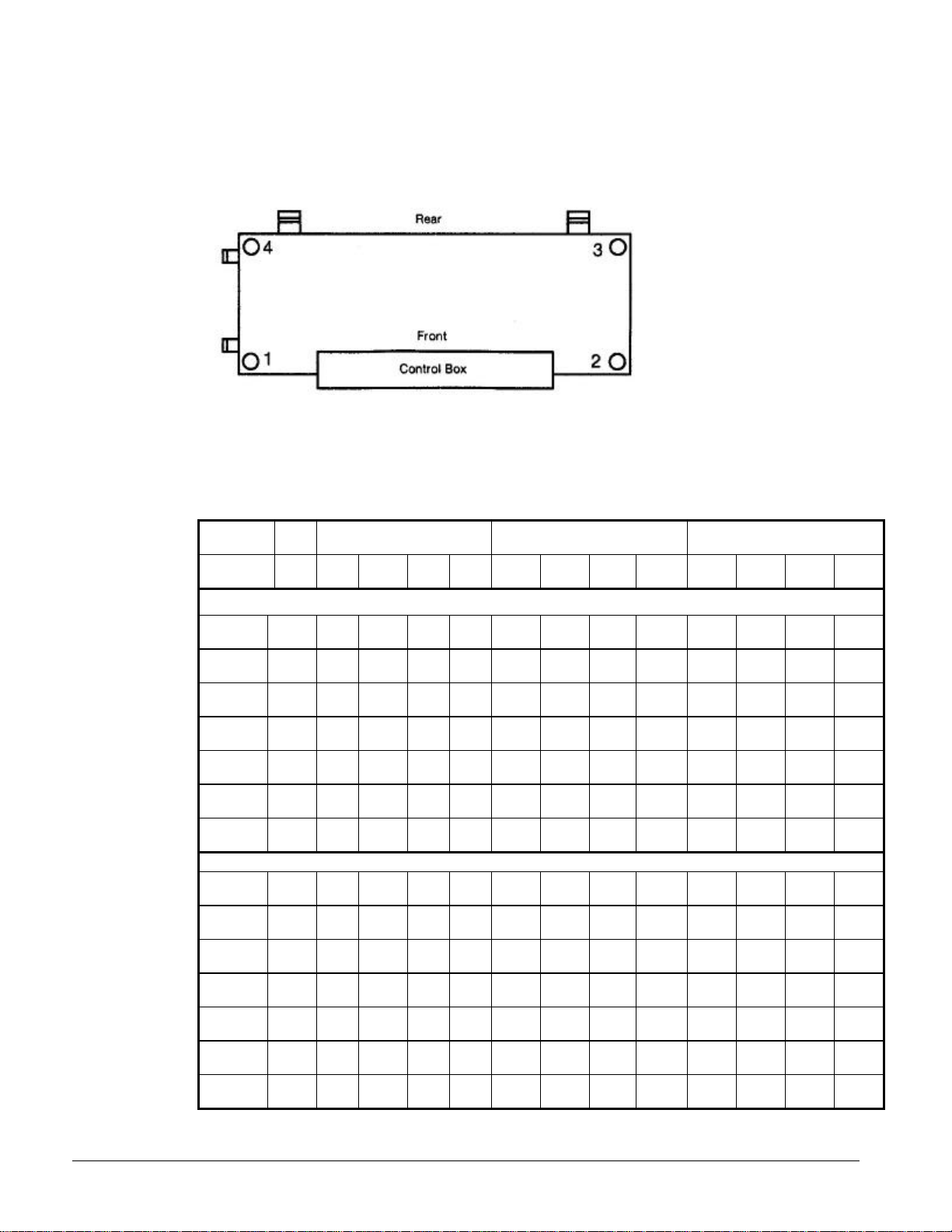
Figure 3, Isolator Locations
Transfer the unit as indicated
under “Moving the Unit.” In all
cases, set the unit in place and
level with a spirit level. When
spring type isolators are
required, install springs running
under the main unit supports.
Adjust spring type mountings
so that upper housing clears
lower housing by at least ¼”
(6mm) and not more than ½” (13mm). A rubber anti-skid pad should be used under isolators if holddown bolts are not used.
Vibration eliminators in all water piping connected to the water chiller are recommended to avoid
straining the piping and transmitting vibration and noise.
Table 2, Weights & Mountings
Unit
Size
WHR100F
WHR110F
WHR120F
WHR135F
WHR150F
WHR165F
WHR180F
WHR100F
WHR110F
WHR120F
WHR135F
WHR150F
WHR165F
WHR180F
Opr.
Wt.
Lbs
(kg)
6170
(2799)
6340
(2876)
6480
(2939)
7195
(3264)
9195
(4171)
9290
(4214)
9300
(4218)
4705
(2134)
4730
(2146)
5245
(2379)
5440
(2468)
6080
(2754)
6500
(2944)
6900
(3130)
Corner Weight Lbs (kg) Neoprene-In-Shear Mountings Spring-Flex Mountings
1 2 3 4 1 2 3 4 1 2 3 4
ARRANGEMENT W – WHR WITH WATER COOLED CONDENSERS
1473
1386
1605
1706
(668)
(629)
(728)
1513
1424
1650
(686)
(646)
(749)
1530
1453
1703
(694)
(659)
(773)
1665
1634
1929
(755)
(741)
(875)
2171
2201
2362
(985)
(999)
(1072)
(1117)
2191
2227
2388
(994)
(1010)
(1083)
(1127)
2195
2225
2390
(996)
(1009)
(1084)
(1130)
ARRANGEMENT A – WHR WITHOUT WATER-COOLED CONDENSERS
1082
1035
1270
(491)
(470)
(576)
1088
1041
1277
(494)
(472)
(579)
1206
1154
1416
(547)
(524)
(642)
1251
1197
1469
(568)
(543)
(666)
1399
1337
1641
(634)
(606)
(743)
1495
1431
1756
(677)
(648)
(795)
1535
1565
1870
(696)
(710)
(848)
4-Red 4-Red 4-Red 4-Red CP2-32 CP2-32 CP2-32 CP2-32
(774)
1753
4-Red 4-Red 4-Red 4-Red CP2-32 CP2-32 CP2-32 CP2-32
(795)
1794
4-Red 4-Red 4-Red 4-Red CP2-32 CP2-32 CP2-32 CP2-32
(814)
1967
4-Green4-Green
(892)
2461
4-Gray 4-Gray 4-Gray 4-Gray CP4-31 CP4-31 CP4-31 CP4-31
2484
4-Gray 4-Gray 4-Gray 4-Gray CP4-31 CP4-31 CP4-31 CP4-31
2490
4-Gray 4-Gray 4-Gray 4-Gray CP4-31 CP4-31 CP4-31 CP4-31
1318
4-Red 4-Red 4-Red 4-Red CP2-31 CP2-31 CP2-31 CP2-31
(598)
1324
4-Red 4-Red 4-Red 4-Red CP2-31 CP2-31 CP2-31 CP2-31
(601)
1469
4-Red 4-Red 4-Red 4-Red CP2-31 CP2-31 CP2-31 CP2-31
(666)
1523
4-Red 4-Red 4-Red 4-Red CP2-32 CP2-32 CP2-32 CP2-32
(691)
1703
4-Red 4-Red 4-Red 4-Red CP2-32 CP2-32 CP2-32 CP2-32
(771)
1820
4-Green4-Green
(824)
1930
4-Green4-Green
(876)
4-
4-Green CP4-27 CP4-27 CP4-27 CP4-27
Green
4-
4-Green CP4-28 CP4-28 CP4-28 CP4-28
Green
4-
4-Green CP4-28 CP4-28 CP4-28 CP4-28
Green
6 WHR 100F through 180F IOMM WHR
Page 7
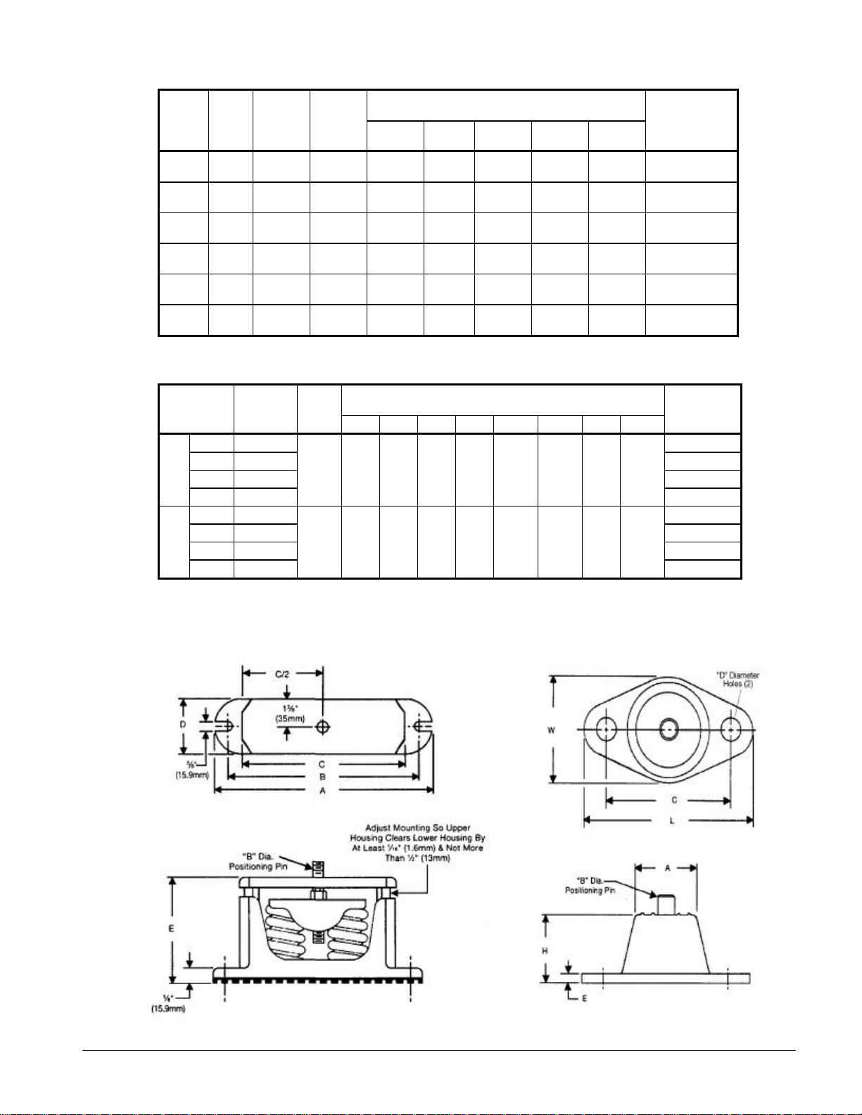
Table 3, Spring Flex Isolators
Dimensions
In. (mm)
2¾
(70)
2¾
(70)
5
(127)
5
(127)
5
(127)
5
(127)
5
(149)
5
(149)
6
(156)
6
(156)
6
(156)
6
(156)
Part Number
886-477929A-31
886-477929A-32
886-580513A-27
886-580513A-28
886-580513A-31
886-580513A-32
Type Color
CP-2-31 Gray
CP-2-32 White
CP-4-27 Orange
CP-4-28 Green
CP-4-31 Gray
CP-4-32 White
Max.
Load
Each
Lbs. (kg)
2200
(998)
2600
(1180)
3000
(1361)
3600
(1633)
4400
(1996)
5200
(2359)
Defl.
In. (mm)
0.83
(21)
0.70
(17.8)
1.10
(27.9)
1.00
(25.4)
0.80
(20.3)
0.70
(17.8)
A B C D E
10¼
(260)9¼(235)8(203)
10¼
(260)9¼(235)8(203)
10¼
(260)9¼(235)7½(191)
10¼
(260)9¼(235)7½(191)
10¼
(260)9¼(235)7½(191)
10¼
(260)9¼(235)7½(191)
Table 4, Neoprene-in-Shear Isolators
Dimensions
In. (mm)
9
⁄16
(14.3)
(14.3)
(6.4)1¾(44.4)5½(165)3(85.7)
9
⁄16
(6.4)1¾(44.4)5½(165)3(85.7)
¼
¼
Type
Max. Load
Each
Lbs. (kg)
Defl.
In.
(mm)
A B C D E H L W
Black 250 (113) 216397A-04
Red 525 (238) 216397A-01
RP-3
Green 750 (340) 216397A-03
0.25
(6.4)2½(63.5)½(12.7)4(104.8)
Gray 1100 (499)
Black 1500 (681) 216398A-04
Red 2250 (1021) 216398A-01
RP-4
Green 3300 (1497) 216398A-03
0.25
(6.4)3¾(95.3)(15.9)5(14.3)
Gray 4000 (1815)
McQuay
McQuay
Part Number
216397A-05
216398A-05
Figure 4, Spring Flex Mountings Figure 5, Single Neoprene-in-Shear
Mounting
IOMM WHR WHR 100F through 180F 7
Page 8

Water Piping
General
Due to the variety of piping practices, it is advisable to follow the recommendations of local
authorities. They can supply the installer with the proper building and safety codes required for a
safe and proper installation.
Basically, the piping should be designed with a minimum number of bends and changes in elevation to
keep system cost down and performance up. It should contain:
1. All piping should be installed and supported to prevent the unit connections from bearing any
2. Vibration eliminators to reduce vibration and noise transmission to the building.
3. Shutoff valves to isolate the unit from the piping system during unit servicing.
4. Manual or automatic air vent valves at the high points of the system. Drains should be placed at
5. Some means of maintaining adequate system water pressure (e.g., expansion tank or regulating
6. Temperature and pressure indicators located within 3 feet (0.9 meters) of the inlet and outlet of the
7. A strainer or some means of removing foreign matter from the water before it enters the pump is
8. A cleanable strainer should also be placed in the water lines just prior to the inlets of the
9. Any water piping to the unit must be protected to prevent freezing. Consult the ASHRAE
10. If the unit is used as a replacement chiller on a previously existing piping system, the system
11. The total quantity of water in the system should be sufficient to prevent frequent “on-off”
12. In the event glycol is added to the water system, as an afterthought for freeze protection,
13. A preliminary leak check of the water piping should be made before filling the system.
14. Many installations can realize considerable energy savings by reducing the chilled water flow
strain or weight of the system piping.
the lowest points in the system.
valve).
vessels to aid in unit servicing.
recommended. It should be placed far enough upstream to prevent cavitation at the pump inlet
(consult pump manufacturer for recommendations). The use of a strainer will prolong pump life
and thus keep system performance up.
evaporator and condenser. This will aid in preventing foreign material from entering and
decreasing the performance of the evaporator and condenser.
handbook for standard industry practice.
should be thoroughly flushed prior to unit installation and then regular water analysis and
chemical water treatment on the evaporator and condenser is recommended immediately at
equipment start-up.
cycling. The total quantity of water, in the system, turnover rate should not be less than 7
minutes.
recognize that the refrigerant suction pressure will be lower, cooling performance less, and water
side pressure drop is greater. If the percentage of glycol is large, or if propylene is employed
instead of ethylene glycol, the added pressure drop and loss of performance could be substantial.
Reset the freezestat and low leaving water alarm temperatures. The freezestat is factory set to
default at 36°F (2.2°C). Reset the freezestat setting to approximately 4° to 5°F (2.3° to 2.8°C)
below the leaving chilled water setpoint temperature. See the section titled “Glycol Solutions” for
additional information concerning glycol.
proportional to load and thereby reducing pump power input. Variable flow systems are
approved for WHR units provided
• The minimum flow does not go below the value shown in Table 6.
• The rate of flow change does not exceed 10 percent per minute.
8 WHR 100F through 180F IOMM WHR
Page 9
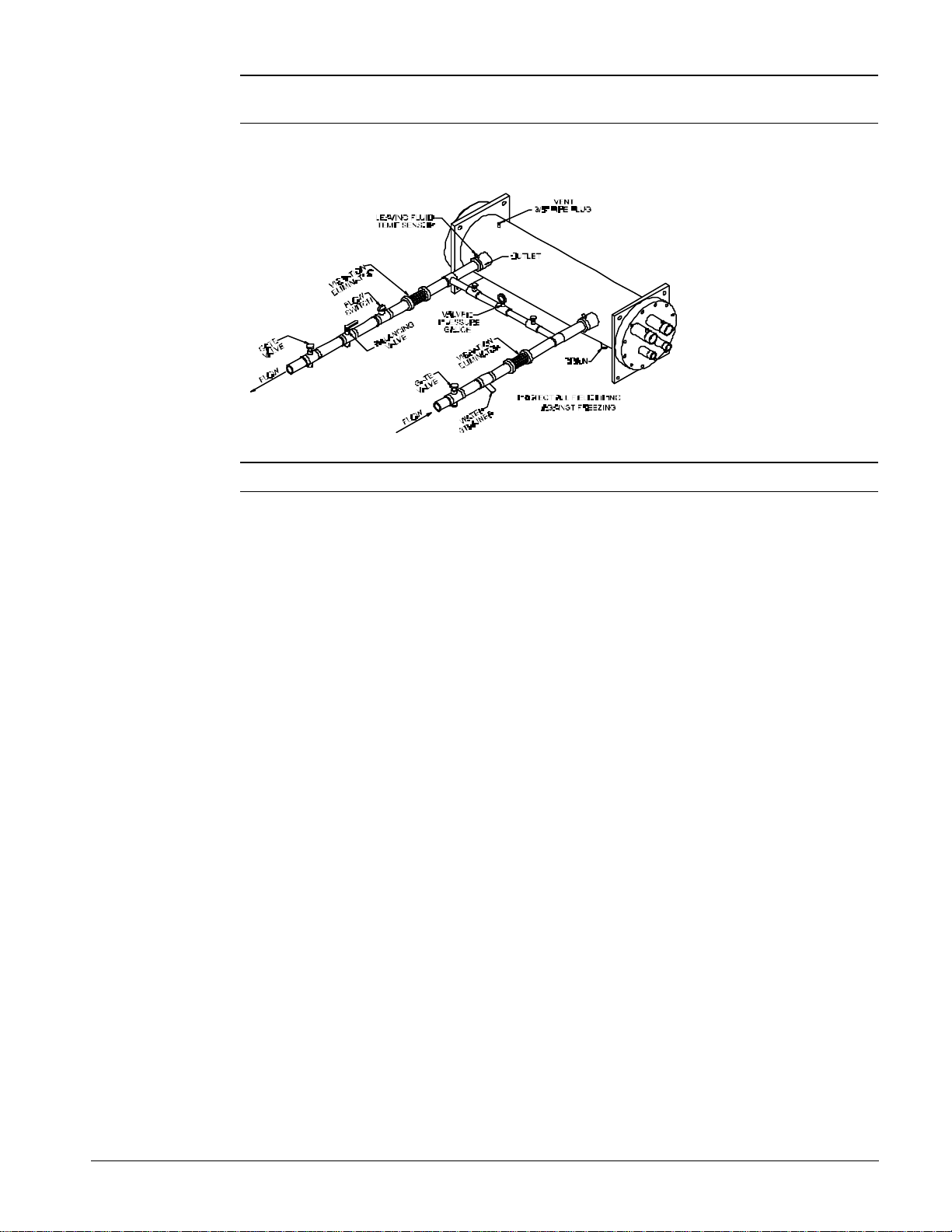
Note: A water flow switch or pressure differential switch must be mounted in the evaporator
water lines to signal that there is water flow before the unit will start.
Figure 6, Typical Field Evaporator Water Piping
Note: Chilled water piping should be insulated.
Chilled Water Piping
The system water piping must be flushed thoroughly prior to making connections to the unit
evaporator. It is recommended that a strainer of 40 mesh be installed in the return water line before the
inlet to the chiller. Lay out the water piping so the chilled water circulating pump discharges into the
evaporator inlet.
The return water line must be piped to the evaporator inlet connection and the supply water line must
be piped to the evaporator outlet connection. If the evaporator water is piped in the reverse direction,
which is not recommended, a substantial decrease in capacity and efficiency of the unit will be
experienced.
A flow switch must be installed in the horizontal piping of the supply (evaporator outlet) water line to
provide water flow before starting the unit.
Drain connections should be provided at all low points in the system to permit complete drainage of
the system. Air vents should be located at the high points in the system to purge air out of the
system. A vent connection, located on top of the evaporator vessel, permits the purging of air out of
the evaporator. Air purged from the water system prior to unit start-up provides adequate flow
through the vessel and prevents safety cutouts on the freeze protection. System pressures can be
maintained by using an expansion tank as a combination pressure relief and reducing valve.
Pressure gauges should be installed in the inlet and outlet water lines to the evaporator. Pressure
drop through the evaporator should be measured to calculate proper gpm (L/s) as specified in the
Physical Data section tables. Vibration eliminators are recommended in both the supply and return
water lines.
Chilled water piping should be insulated to reduce heat loss and prevent condensation. Complete
unit and system leak tests should be performed prior to insulating the water piping. Insulation with a
vapor barrier would be the recommended type of insulation. If the vessel is insulated, the vent and
drain connections must extend beyond the proposed insulation thickness for accessibility. Chillers
not run in the winter should have their water systems thoroughly drained to protect against freezing.
If the chiller operates year-round, or if the system is not drained for the winter, the chilled water piping
exposed to outdoor ambient should be protected against freezing by wrapping the lines with a heater
cable. Also, an adequate percentage of glycol should be added to the system to further protect the
system during low ambient periods.
IOMM WHR WHR 100F through 180F 9
Page 10
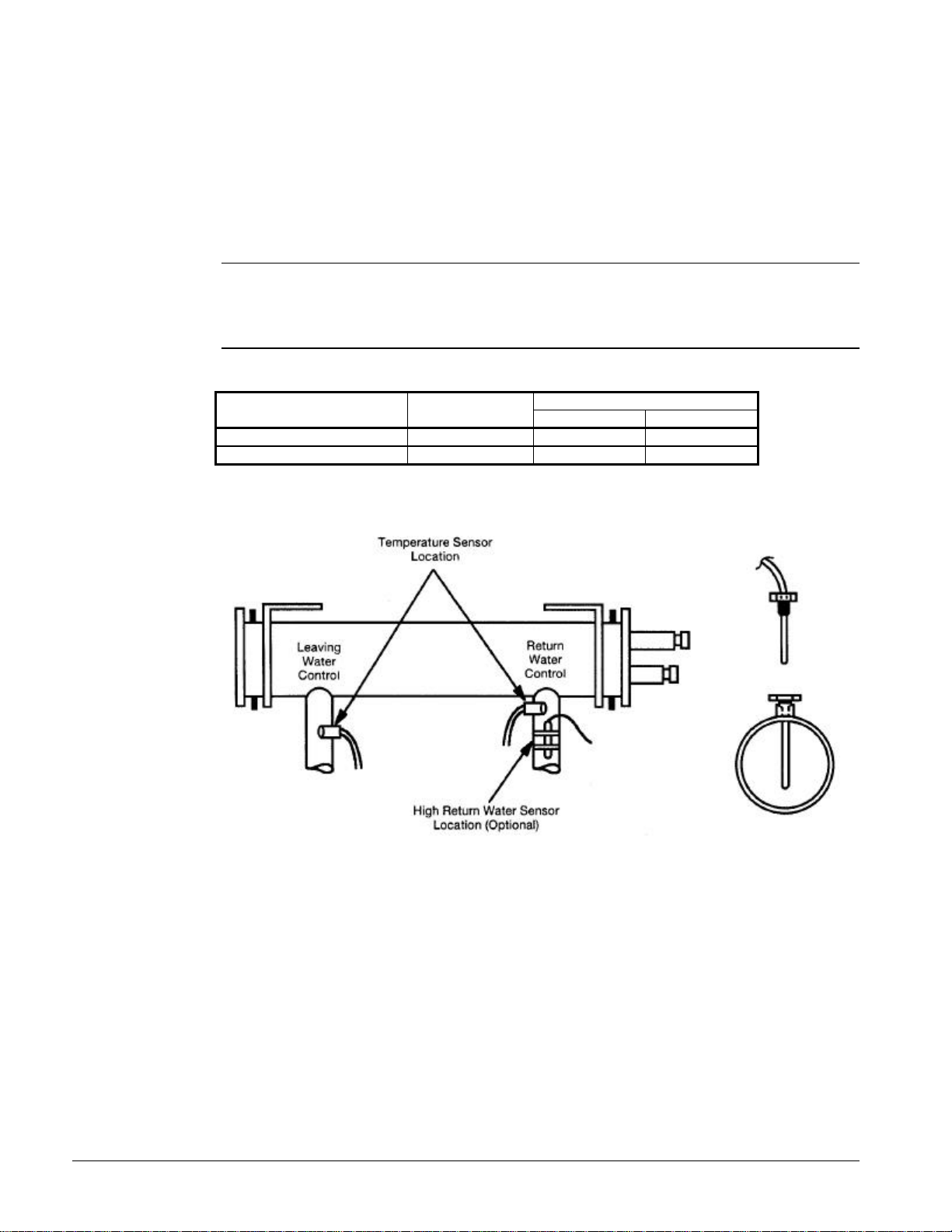
Chilled Water Thermostat
The chilled water sensor is factory installed in the leaving water connection on the evaporator. Care
should be taken not to damage the sensor cable or leadwires when working around the unit. It is also
advisable to check the leadwire before running the unit to be sure that it is firmly anchored and not
rubbing on the frame or any other component. If the sensor is ever removed from the well for
servicing, care must be taken as not to wipe off the heat conducting compound supplied in the well.
Note: See page 48 for additional thermostat information.
CAUTION
The thermostat bulb should not be exposed to water temperatures above 125°F
(51.7°C) since this will damage the control.
Table 5, Models and Sensor Locations
Installation
Model Number
Johnson UNT 33n-1 IOM UNT33n X
MicroTech, Control Manual OM RCPMICRO X
Figure 7, Thermostat Well Installation
Manual Name
Sensor LocationVendor
Return Leaving
Flow Switch
A water flow switch must be mounted in either the entering or leaving water line to provide adequate
water flow and cooling load to the evaporator before the unit can start. This will safeguard against
slugging the compressors on start-up. It also serves to shut down the unit in the event that water
flow is interrupted to guard against evaporator freeze-up.
A flow switch is available from McQuay under ordering number 01750330. It is a “paddle” type switch
and adaptable to any pipe size from 1” (25mm) to 6” (152mm) nominal. Certain minimum flow rates are
required to close the switch and are listed in Table 6. Installation should be as shown in Figure 8.
Electrical connections in the unit control center should be made at terminal 18 and B14. The normally
open contacts of the flow switch should be wired between these two terminals. There is also a set of
normally closed contacts on the switch that could be used for an indicator light or an alarm to indicate
when a “no flow” condition exists.
10 WHR 100F through 180F IOMM WHR
Page 11
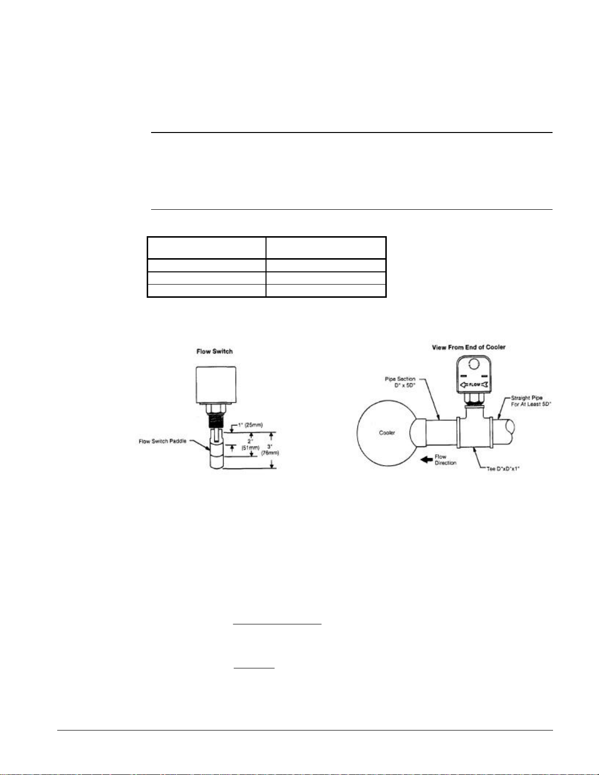
1. Apply pipe sealing compound to only the threads of the switch and screw unit into D” x D” x 1
(25mm) reducing tee (see Figure 8). The flow arrow must be pointed in the correct direction.
2. Piping should provide a straight length before and after the flow switch of at least five times the
pipe diameter.
3. Trim flow switch paddle if needed to fit the pipe diameter. Make sure paddle does not hang up in
pipe.
CAUTION
Make sure the arrow on the side of the switch is pointed in the direction of flow. The
flow switch is designed to handle the control voltage and should be connected
according to the wiring diagram (see wiring diagram inside control box door).
Incorrect installation will cause improper operation and possible evaporator damage.
Table 6, Flow Switch Minimum Flow Rates
Nominal Pipe Size
Inches (mm)
4 (101.6) 39.70 (2.50)
5 (127.0) 58.70 (3.70)
6 (152.4) 79.20 (5.00)
Minimum Required Flow to
Activate Switch – GPM (l/s)
Figure 8, Flow Switch
Glycol Solutions
The system glycol capacity, glycol solution flow rate in gpm (lps), pressure drop through the cooler,
and system pressure drop can be calculated using the following formulas and table.
1. Capacity — Capacity is reduced from that with plain water. To find the reduced value multiply the
chiller’s water system capacity by the capacity correction factor C to find the chiller’s capacity in
the glycol system.
2. Gpm —To determine evaporator gpm (or ∆T) knowing ∆T (or gpm) and capacity:
GPMGlycol
24
=
For Metric Applications — To determine evaporator lps (or ∆T) knowing ∆T (or lps) and kW:
LpsGlycol
IOMM WHR WHR 100F through 180F 11
kW
=
18.4
CapacityGlycolx
T
∆
Tx
∆
( )
FromTablesGx
TablesfromGFlowx
Page 12
3. Pressure Drop — To determine glycol pressure drop through the cooler, enter the water pressure
drop graph on page 14 at the water flow. Multiply the water pressure drop found there by P to
obtain corrected glycol pressure drop.
4. To determine glycol system kW, multiply the water system kW by factor K.
Test coolant with a clean, accurate glycol solution hydrometer (similar to that found in service
stations) to determine the freezing point. Obtain percent glycol from the freezing point table below. On
glycol applications the supplier normally recommends that a minimum of 25% solution by weight be
used for protection against corrosion.
Note: The effect of glycol in the condenser is negligible. As glycol increases in temperature,
its characteristics have a tendency to mirror those of water. Therefore, for selection purposes,
there is no derate in capacity for glycol in the condenser.
Table 7, Ethylene Glycol
Freezing PointPercent
Glycol
10 26 -3 0.991 0.996 1.013 1.070
20 18 -8 0.982 0.992 1.040 1.129
30 7 -14 0.972 0.986 1.074 1.181
40 -7 -22 0.961 0.976 1.121 1.263
50 -28 -33 0.946 0.966 1.178 1.308
°F °C
C (Capacity) K (Power) G (Flow)
P (Pressure
Drop)
Table 8, Propylene Glycol
Freezing PointPercent
Glycol
10 26 -3 0.987 0.992 1.010 1.068
20 19 -7 0.975 0.985 1.028 1.147
30 9 -13 0.962 0.978 1.050 1.248
40 -5 -21 0.946 0.971 1.078 1.366
50 -27 -33 0.929 0.965 1.116 1.481
°F °C
C (Capacity) K (Power) G (Flow)
P (Pressure
Drop)
CAUTION
Do not use an automotive grade antifreeze. Industrial grade glycols must be used.
Automotive antifreeze contains inhibitors which all cause plating on the copper tubes
within the chiller evaporator. The type and handling of glycol used must be
consistent with local codes.
Condenser Water Piping
Arrange the condenser water so the water enters the bottom connection of the condenser. The
condenser water will discharge the condenser from the top connection. Failing to arrange the
condenser water as stated above will negatively affect the capacity and efficiency.
Pressure gauges should be installed in the inlet and outlet water lines to the condenser. Pressure drop
through the condenser should be measured to calculate proper gpm (L/s) as specified on page 15.
Vibration eliminators are recommended in both the supply and return water lines.
Water cooled condensers can be piped for use with cooling towers, well water, or heat recovery
applications. Cooling tower applications should be made with consideration to freeze protection and
scaling problems. Contact the cooling tower manufacturer for equipment characteristics and
limitations for the specific application.
12 WHR 100F through 180F IOMM WHR
Page 13
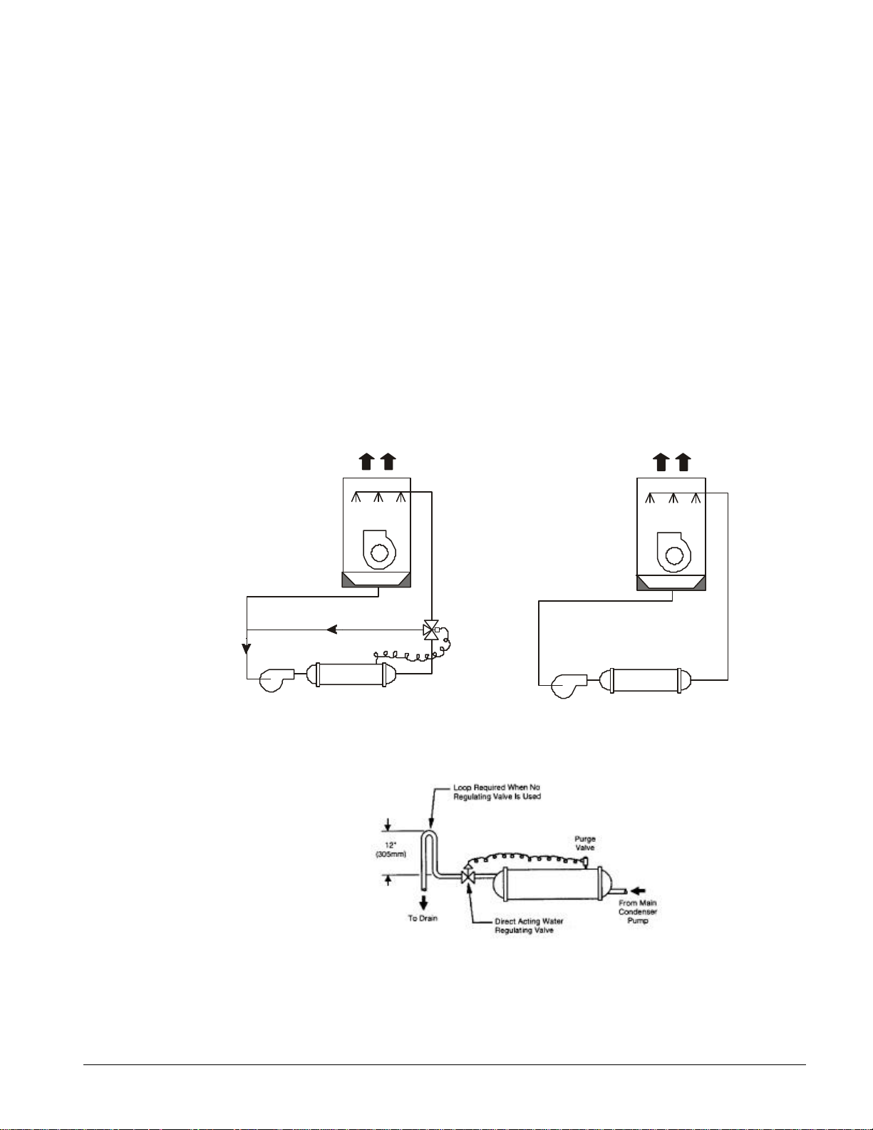
Head Pressure Control, Tower System
Some means of controlling operating head pressure must be provided. Fan cycling and/or modulating
discharge dampers on the cooling towers are often used as shown in Figure 10. A three-way bypass
valve around the tower as shown in Figure 9 is also very common. The minimum entering tower
condenser water temperature is 60°F (16°C). In Figure 10 the capacity of the cooling tower is
controlled through damper and/or fan modulation. These typical systems, depending on the specific
application, must maintain a constant minimum condensing pressure, regardless of temperature
conditions and must provide enough head pressure for proper thermal expansion valve operation.
Note also that both systems provide full water flow to the condenser.
Head Pressure Control, Well Water System
When using city or well water for condensing refrigerant, a direct acting water regulating valve should
be installed in the outlet piping of each condenser (see Figure 11). The condenser purge valve
provides a convenient pressure tap for the regulating valve. The valve can modulate in response to
head pressure. On shutdown it closes, preventing water from siphoning out of the condenser.
Siphoning causes condenser water side drying and accelerates fouling. Figure 11 illustrates the
recommendation of a loop at the outlet end when no valve is used.
Figure 9, Three-way Water Valve Figure 10, Fan Modulation
Cooling
Tower
Condenser
Cooling
Tower
Condenser
Figure 11, Well Water Cooling System
IOMM WHR WHR 100F through 180F 13
Page 14
Water Pressure Drop
The vessel flow rates must fall between the minimum and maximum values shown on the appropriate
evaporator and condenser curves. Flow rates below the minimum values shown will result in laminar
flow that will reduce efficiency, cause erratic operation of the electronic expansion valve and could
cause low temperature cutoffs. On the other hand, flow rates exceeding the maximum values shown
can cause erosion on the evaporator water connections and tubes.
McQuay encourages a minimum glycol concentration of 25% be provided on all glycol applications.
Glycol concentrations below 25% have too little inhibitor content for long-term corrosion protection
of ferrous metals.
Measure the chilled water pressure drop through the evaporator at field installed pressure taps. It is
important not to include valves or strainers in these readings.
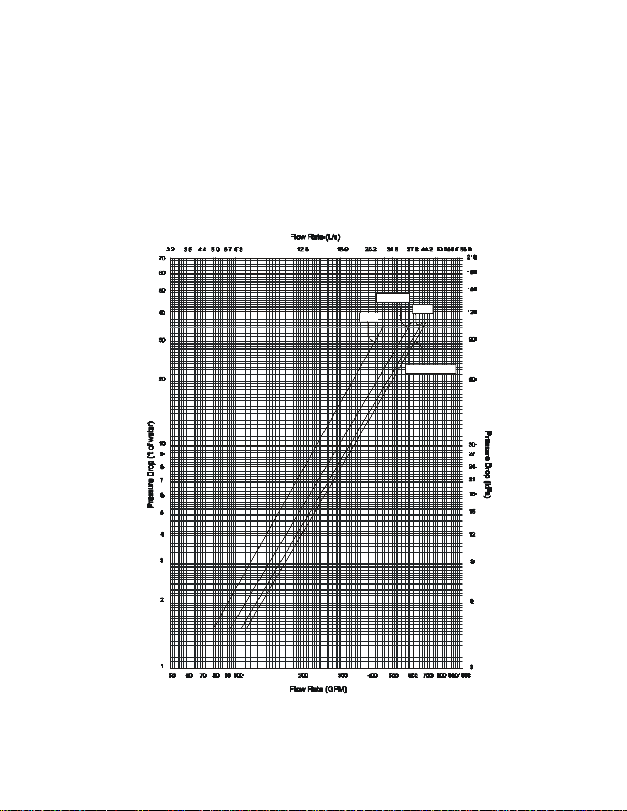
Figure 12, Evaporator Water Pressure Drop, WHR 100F through 180F
110-120
100
135
150-165-180
Flow Rates: Evaporator flow rates must be within the flow limits set by the pressure
drop curve for each unit.
14 WHR 100F through 180F IOMM WHR
Page 15
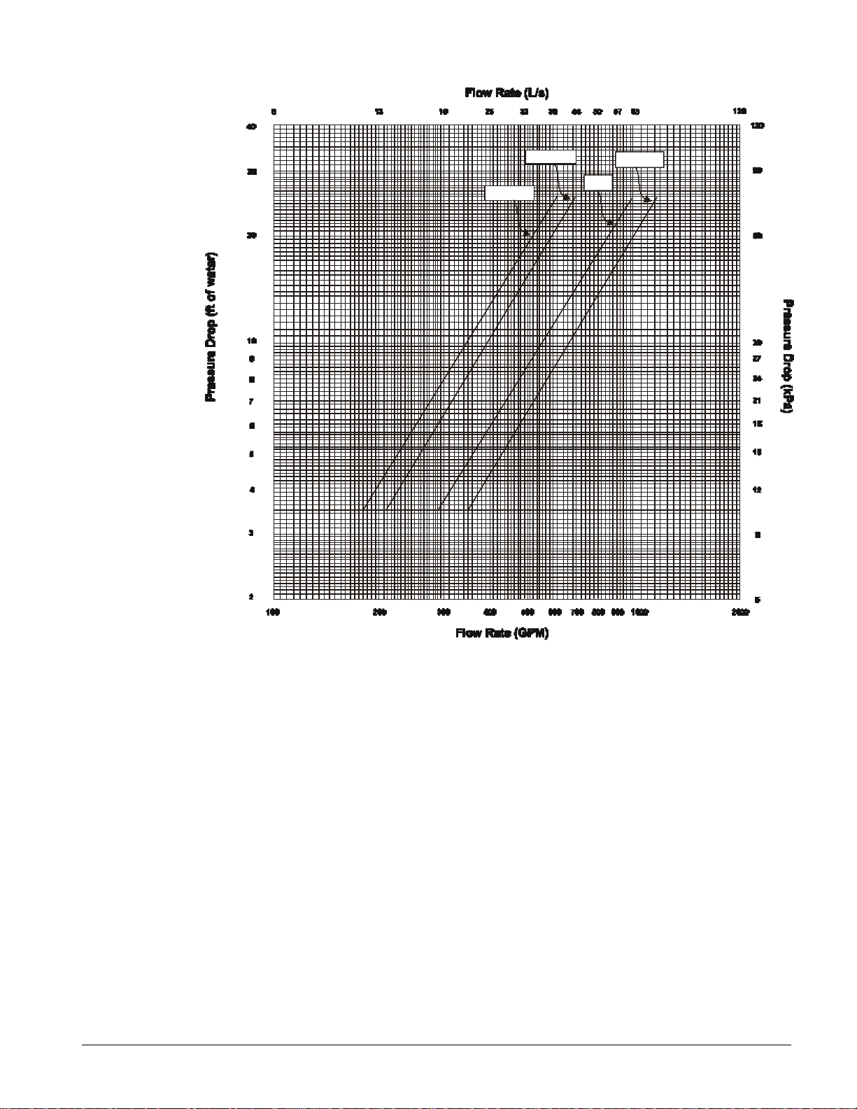
Figure 13, Condenser Water Pressure Drop, WHR 100F through 180F
100-110
120-135
165-180
150
Flow Rates: Condenser flow rates must be within the flow limits set by the pressure drop curve for
each unit.
IOMM WHR WHR 100F through 180F 15
Page 16

Refrigerant Piping
Unit with Remote Condenser
General
For remote condenser application such as an air cooled condenser, the chillers are shipped containing
a Refrigerant 22 holding charge. It is important that the unit be kept tightly closed until the remote
condenser is installed, piped to the unit and the high side evacuated.
Refrigerant piping, to and from the unit, should be sized and installed according to the latest ASHRAE
Handbook. It is important that the unit piping be properly supported with sound and vibration
isolation between tubing and hanger and that the discharge lines be looped at the condenser and
trapped at the compressor to prevent refrigerant and oil from draining into the compressor discharge
manifold. Looping the discharge line also provides greater line flexibility.
The discharge gas valves, liquid line solenoids, filter-driers, moisture indicators, and thermostatic
expansion valves are all provided as standard equipment with the water chiller.
A liquid line shutoff valve must be added in the field on remote condenser units (Arrangement A)
between the liquid line filter-drier and remote condenser.
After the equipment is properly installed, the unit can be charged with Refrigerant 22, then run at
design load conditions, adding charge until the liquid line sightglass is clear, with no bubbles flowing
to the expansion valve. Total operating charge will depend on the air-cooled condenser used. The
charge for water-cooled units is shown in Table 9 through Table 12.
Note: On the Arrangement A units (units with remote condensers), the installer is required to
record the refrigerant charge by stamping the total charge and the charge per circuit on the
serial plate in the appropriate blocks provided for this purpose.
Water chillers without condensers require field piping to a remote condenser of some type. The
design of refrigerant piping when using air-cooled condensers involves a number of considerations
not commonly associated with other types of condensing equipment. The following discussion is
intended for use as a general guide to sound, economical and trouble-free piping of air-cooled
condensers.
Discharge lines must be designed to handle oil properly and to protect the compressor from damage
that can result from condensing liquid refrigerant in the line during shutdown. Total friction loss for
discharge lines of 3 to 6 psig (20.7 to 41.4 kPa) is considered good design. Careful consideration must
be given for sizing each section of piping to insure that gas velocities are sufficient at all operating
conditions to carry oil. If the velocity in a vertical discharge riser is too low, considerable oil can
collect in the riser and the horizontal header, causing the compressor to lose its oil and result in
damage due to lack of lubrication. When the compressor load is increased, the oil that had collected
during reduced loads can be carried as a slug through the system and back to the compressor, where a
sudden increase of oil concentration can cause liquid slugging and damage to the compressor.
Any horizontal run of discharge piping should be pitched away from the compressor approximately
1/8 inch (6.4mm) per foot (meter) or more. This is necessary to move by gravity any oil lying in the
header. Oil pockets must be avoided as oil needed in the compressor would collect at such points and
the compressor crankcase can become starved.
It is recommended that any discharge lines coming into a horizontal discharge header rise above the
center line of the discharge header. This is necessary to prevent any oil or condensed liquid from
draining to the top heads when the compressor is not running.
It is important that the liquid reach the expansion valve with no presence of flash gas since this gas
will reduce the capacity of the valve. Because “flashing” can be caused by a pressure drop in the
16 WHR 100F through 180F IOMM WHR
Page 17

liquid lines, the pressure losses due to friction and changes in static head should be kept to a
minimum.
A check valve must be installed in the liquid line in all applications where the ambient temperature can
get below the equipment room temperature. This prevents liquid migration to the condenser, helps
maintain a supply of refrigerant in the liquid line for initial start-up and keeps liquid line pressure high
enough on “off” cycle to keep the expansion valve closed.
On systems as described above, a relief valve or relief type check valve must be used in the liquid line
as shown in piping systems Figure 14 to relieve dangerous hydraulic pressures that could be created
as cool liquid refrigerant in the line between the check valve and expansion or shutoff valve warms up.
A relief device is also recommended in the hot gas piping at the condenser coil as shown in Figure 14
and Figure 15.
Typical Arrangements
Figure 14 illustrates a typical piping arrangement involving a remote air cooled condenser located at a
higher elevation than the compressor and receiver. This arrangement is commonly encountered when
the air-cooled condenser is on a roof and the compressor and receiver are on grade level or in a
basement equipment room.
In this case, the design of the discharge line is very critical. It must be properly sized for full load
condition and have sufficient gas velocity at reduced loads to carry oil up through the discharge line
and condenser coil.
Notice in all illustrations that the hot gas line is looped at the bottom and top of the vertical run. This
is done to prevent oil and condensed refrigerant from flowing back into the compressor and causing
damage. The highest point in the discharge line should always be above the highest point in the
condenser coil; it is advisable to include a purging vent at this point to release noncondensables from
the system.
The inverted loop shown at the top of the riser is not required as long as the horizontal run to the
condenser is sloped downward to the condenser
The optional receiver is desirable in cases when the condenser cannot hold the entire refrigerant
charge or when a back-flooding type of head pressure control is used. The receiver is usually
bypassed during normal operation (except for back-flooding designs). It is important that the
refrigerant pass through the subcooler just prior to going to the expansion valve so that maximum
subcooling is in effect.
Figure 15 illustrates another common application where the air-cooled condenser is located on
essentially the same level as the compressor and receiver. The discharge line piping in this case is not
too critical. The principal program encountered with this arrangement is that there is frequently
insufficient vertical distance to allow free drainage of liquid refrigerant from the condenser coil to the
receiver.
NOTE : The illustrations show only one refrigerant circuit for the sake of clarity. All WHR units will
have two refrigerant circuits going to the condenser.
IOMM WHR WHR 100F through 180F 17
Page 18
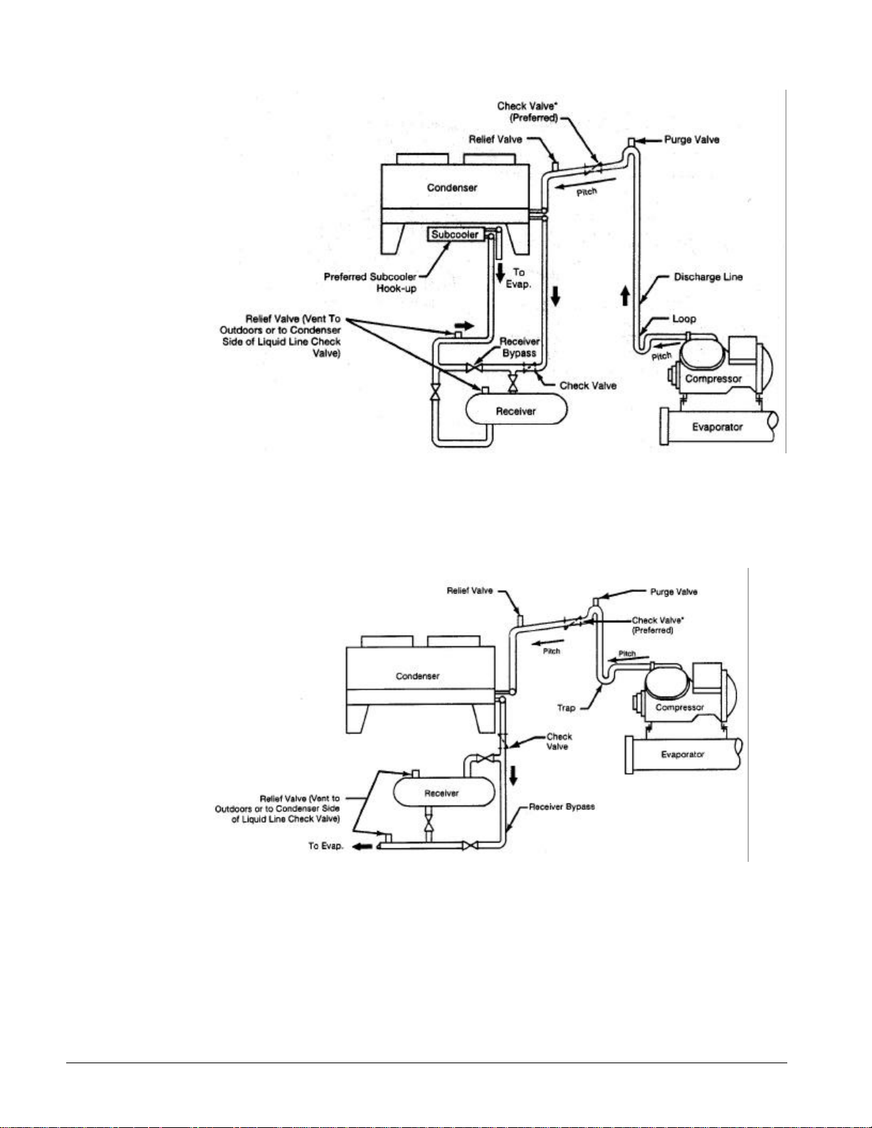
Figure 14, Condenser Above Compressor and Receiver
Figure 15, Condenser and Compressor on Same Level
18 WHR 100F through 180F IOMM WHR
Page 19

Unit with Factory Mounted Condensers
Units with factory mounted condensers are provided with complete refrigerant piping and full
operating refrigerant charge at the factory.
There is a remote possibility on Arrangement W units utilizing low temperature pond or river water in
the condenser that if the water valves leak the condenser and liquid line refrigerant temperature could
go below the equipment room temperature on the “off” cycle. This could open the expansion valve
and cause the unit to pumpdown every two hours. This problem only arises during periods when
cold water continues to circulate through the condenser and the unit remains off due to satisfied
cooling load.
If this condition occurs:
1. Cycle the condenser pump off with the unit.
2. Check the liquid line solenoid valve for proper operation.
Relief Valve Piping
The current ANSI/ASHRAE Standard 15 specifies that pressure relief valves on vessels containing
Group 1 refrigerant (R-22) “shall discharge to the atmosphere at a location not less than 15 feet (4.6
meters) above the adjoining ground level and not less than 20 feet (6.1 meters) from any window,
ventilation opening or exit in any building.” The piping must be provided with a rain cap at the
outside terminating point and a drain at the low point on the vent piping to prevent water buildup on
the atmospheric side of the relief valve. In addition, a flexible pipe section should be installed in the
line to eliminate any piping stress on the relief valve(s).
The size of the discharge pipe from the pressure relief valve shall not be less than the size of the
pressure relief outlet. When two or more vessels are piped together, the common header and piping to
the atmosphere shall not be less than the sum of the area of the relief valve outlets connected to the
header. Fittings should be provided to permit vent piping to be easily disconnected for inspection or
replacement of the relief valve.
NOTE: Provide adequate fittings in piping to permit repair or replacement of relief valve.
Figure 16, Relief Valve Piping
IOMM WHR WHR 100F through 180F 19
Page 20

Dimensional Data
FW Water-Cooled
Figure 17, WHR 100FW through WHR 135FW
WHR
MODEL
NUMBER
100FW 142 3/4 (3626) 34 (864) 77 (1956) 55 (1397) 32 (829) 13 (343)
110FW 142 3/4 (3626) 34 (864) 77 (1956) 56 (1422) 32 (829) 13 (343)
120FW 142 3/4 (3626) 34 (864) 77 (1956) 56 (1422) 32 (835) 13 (343)
135FW 142 3/4 (3626) 34 (864) 77 (1956) 56 (1422) 32 (835) 13 (343)
Note: Control box size: 76” (1930mm) L x 38½” (978mm) H x 7¼” (184mm) D.
20 WHR 100F through 180F IOMM WHR
Maximum Overall
Dimensions
L W H X Y Z
Center of
Gravity
Page 21

Figure 18, WHR-150FW through WHR-180FW
WHR
MODEL
NUMBER
150FW 146 (3705) 35 (889) 79 (2007) 55 (1397) 36 (914) 13 (330)
165FW 146 (3705) 35 (889) 79 (2007) 55 (1397) 36 (914) 13 (330)
180FW 146 (3705) 35 (889) 79 (2007) 55 (1397) 36 (914) 13 (330)
Note: Control box size: 76” (1930mm) L x 38½” (978mm) H x 7¼” x (184mm) D.
Maximum Overall
Dimensions
L W H X Y Z
Center of
Gravity
IOMM WHR WHR 100F through 180F 21
Page 22

FA Remote Condenser
Figure 19, Dimensions, WHR 100FA – WHR 135FA
WHR
MODEL
NO.
100FW
110FW
120FW
135FW
Maximum Overall
Dimensions
L W H A C D P T X Y Z Liquid Disc.
142¾
(3626)34(864)
142¾
(3626)34(864)
142¾
(3626)34(864)
142¾
(3626)34(864)
64¾
(1645)5½(138)18(457)6(152)6(152)21(533)
64¾
(1645)5½(138)18(457)6(152)6(152)21(533)
64¾
(1645)5½(138)18(457)6(152)6(152)21(533)
64¾
(1645)5½(138)18(457)6(152)6(152)21(533)
Evaporator. Water
Connections. (Victaulic)
Center of Gravity
55½
(1410)
55½
(1410)29737)
55
(1407)
56¼
(1429)
28¾
(730)
29
740)13(330)
29¾
756)13(330)
13
(334)
13
(334)
Refrigerant
Connections (OD)
1 1
1 1
1 1
1 1
22 WHR 100F through 180F IOMM WHR
Page 23

Figure 20, Dimensions WHR 150FA - 180FA
WHR
MODEL
NO.
150FA
165FA
180FA
Maximum Overall
Dimensions
L W H A C D
145
(3705)35(889)
145
(3705)35(889)
145
(3705)35(889)
64¾
(1645)4(1049)19(483)6(152)6(152)
64¾
(1645)4(1049)19(483)6(152)6(152)
64¾
(1645)4(1049)19(483)6(152)6(152)
Evaporator Water
Connections (Victaulic)
Center of Gravity
P T
21
(543)54(1372)
21
(543)54(1372)
21
(543)54(1372)32(813)16(406)
X Y Z Liquid Disc.
32½
(826)16(406)
32¼
(819)16(406)
Refrigerant
Connections (OD)
1 1
1 1
1 1
IOMM WHR WHR 100F through 180F 23
Page 24

Physical Data
FW Water-Cooled
Table 9, WHR-100FW - WHR-13 5FW
WHR UNIT SIZE 100FW 110FW 120FW 135FW
Unit capacity @ ARI
conditions tons, (kW) (1)
No. Circuits 2 2 2 2
COMPRESSORS
Nominal Horsepower 30/25 30/25 35/25 35/25 35/25 35/35 35/35 35/35
Number 2 2 2 2 2 2 2 2
Speed RPM 1750 1750 1750 1750
No. of Cylinders 6/4 6/4 6/4 6/4 6/4 6/6 6/6 6/6
Unloading Steps
Oil Charge oz. (l)
CONDENSERS
Number 2 2 2 2
Diameter, in. (mm) 10 3/4 (273)
Tube Length, in. (mm) 120 (3048) 120 (3048) 120 (3048) 120 (3048) 120 (3048) 120 (3048) 120 (3048) 120 (3048)
Design W.P, .psig, (kPa):
Refrigerant Side 450 (3104) 450 (3104) 450 (3104) 450 (3104)
Water Side 225 (1550) 225 (1550) 225 (1550) 225 (1550)
No. of Passes 2 2 2 2 2 2 2 2
Pump-Out Capacity, lb. (kg)
(2)
Connections:
Water Inlet & Outlet, In.,
(mm) (3)
Relief Valve, Flare in.
(mm)
Purge Valve, Flare in.
(mm)
Liquid Subcooling Integral Integral Integral Integral
EVAPORATOR
No. Refrigerant Circuits 2 2 2 2
Diameter, in. (mm) 14 (356) 14 (356) 14 (356) 16 (406)
Tube Length, in. (mm) 120 (3048) 120 (3048) 120 (3048) 120 (3048)
Water Volume, gallons, (l) 38.2 (2.4) 36.1 (2.3) 36.1 (2.3) 45.1 (2.9)
Refrigerant Side D.W.P.,
psig, (kPa)
Water Side D.W.P.
Psig (kPa)
Water Connections:
Inlet & Outlet, in. (mm) (4) 6 (152) 6 (152) 6 (152) 6 (152)
Drain & Vent, (NPT INT.) 3/8 (10) 3/8 (10) 3/8 (10) 3/8 (10)
UNIT DIMENSIONS
Length, in. (mm) 143 (3626) 143 (3626) 143 (3626) 143 (3626)
Width, in. (mm) 34 (864) 34 (864) 34 (864) 34 (864)
Height, in. (mm) 77 (1956) 77 (1956) 77 (1956) 77 (1956)
UNIT WEIGHTS
Operating Weight, lb. (kg) 6170 (2799) 6340 (2876) 6480 (2939) 7195 (3264)
Shipping Weight, lb. (kg) 5980 (2713) 6150 (2790) 6290 (2853) 6895 (3128)
Ref. Charge, lb. (kg) R-22 90 (41) 90 (41) 95 (43) 95 (43) 100 (45) 100 (45) 100 (45) 100 (45)
Ref. Charge, lb. (kg) R-134a 94 (43) 94 (43) 100 (45) 100 (45) 105 (48) 105 (48) 105 (48) 105 (48)
Notes:
1. Certified in accordance with ARI Standard 550/590-98.
2. 80% Full R-22 at 90°F (32°C) per refrigerant circuit.
3. NPT External.
4. Victaulic connections.
98.6 (345) 104.5 (366) 114.5 (401) 132.1 (462)
100-90-80-70
60-50-40-20-0
140/130 140/130 140/130 140/130 140/130 140/140 140/140 140/140
(4.1)/(3.8) (4.1)/(3.8) (4.1)/(3.8) (4.1)/(3.8) (4.1)/(3.8) (4.1)/(4.1) (4.1)/(4.1) (4.1)/(4.1)
10 3/4
(273)
227 (103) 227 (103) 252 (114) 252 (114) 215 (97.5) 215 (97.5) 215 (97.5) 215 (97.5)
3 (76) 3 (76) 3 (76) 3 (76) 3 (76) 3 (76) 3 (76) 3 (76)
1/2 (13) 5/8 (16) 5/8 (16) 5/8 (16)
1/4 & 1/2
(6) & (13)
225 (1552) 225 (1552) 225 (1552) 225 (1552)
175 (1207) 175 (1207) 175 (1207) 175 (1207)
100-90-80-70
60-50-40-20-0
10 3/4 (273) 10 3/4 (273)
1/4 & 1/2
(6) & (13)
100-91-83-64
54-45-36-16-0
10 3/4
(273)
1/4 & 1/2
(6) & (13)
100-92-84-64
48-40-32-16-0
10 3/4 (273) 10 3/4 (273)
1/4 & 1/2
(6) & (13)
10 3/4
(273)
24 WHR 100F through 180F IOMM WHR
Page 25

Table 10, WHR-150FW - WHR-180FW
WHR UNIT SIZE 150FW 165FW 180FW
Unit capacity @ ARI
conditions tons, (kW) (1)
No. Circuits 2 2 2
COMPRESSORS
Nominal Horsepower 40/40 40/40 40/50 40/50 50/50 50/50
Number 2 2 2 2 2 2
Speed RPM 1750 1750 1750
No. of Cylinders 6/6 6/6 6/8 6/8 8/8 8/8
Unloading Steps
Oil Charge oz., (l)
CONDENSERS
Number 2 2 2
Diameter, in. (mm)
Tube Length, in. (mm) 120 (3048) 120 (3048) 120 (3048) 120 (3048) 120 (3048) 120 (3048)
Design W.P., psig (kPa):
Refrigerant Side 450 (3104) 450 (3104) 450 (3104)
Water Side 225 (1550) 225 (1550) 225 (1550)
No. of Passes 2 2 2 2 2 2
Pump-Out Capacity
lb., (kg) (2)
Connections:
Water Inlet & Outlet
in., (mm) (3)
Relief Valve, Flare in.,
(mm)
Purge Valve, Flare in. (mm)
Liquid Subcooling Integral Integral Integral
EVAPORATOR
No. Refrigerant Circuits 2 2 2
Diameter, in. (mm) 18 (457.2) 18 (457.2) 18 (457.2)
Tube Length, in. (mm) 120 (3048) 120 (3048) 120 (3048)
Water Volume, gallons (l) 57.3 (3.6) 57.3 (3.6) 57.3 (3.6)
Refrigerant Side D.W.P., psig,
(kPa)
Water Side D.W.P., psig, (kPa) 175 (1207) 175 (1207) 175 (1207)
Water Connections:
Inlet & Outlet, in. (mm) (4) 6 (152) 6 (152) 6 (152)
Drain & Vent, (NPT INT.) 3/8 (10) 3/8 (10) 3/8 (10)
UNIT DIMENSIONS
Length, in. (mm) 145 (3705) 145 (3705) 145 (3705)
Width, in. (mm) 35 (889) 35 (889) 35 (889)
Height, in. (mm) 79 (2007) 79 (2007) 79 (2007)
UNIT WEIGHTS
Operating Weight, lb., (kg) 9195 (4171) 9290 (4214) 9300 (4218)
Shipping Weight, lb. (kg) 8795 (3989) 8890 (4033) 8900 (4037)
Ref. Charge, lb. (kg) R-22 125 (57) 125 (57) 130 (60) 130 (60) 130 (60) 130 (60)
Ref. Charge, lb. (kg) R-134a 131 (59) 131 (59) 137 (62) 137 (62) 137 (62) 137 (62)
Notes:
1. Certified in accordance with ARI Standard 550/590-98.
2. 80% Full R-22 at 90°F (32°C) per refrigerant circuit.
3. FPT Internal
4. Victaulic connections
148.9 (521) 162.7 (569) 175.0 (612)
100-92-84-64
48-40-32-16-0
225/255
(7.5)/(7.5)
12 3/4
(323.9)
270 (122.5) 270 (122.5) 253 (114.8) 253 (114.8) 253 (114.8) 253 (114.8)
4 (101.6) 4 (101.6) 4 (101.6) 4 (101.6) 4 (101.6) 4 (101.6)
225/255
(7.5)/(7.5)
12 3/4
(323.9)
5/8 (16) 5/8 (16) 5/8 (16)
1/4 & 1/2
(6) & (13)
225 (1552) 225 (1552) 225 (1552)
100-92-81-65
46-38-30-15-0
225/255
(7.5)/(7.5)
12 3/4
(323.9)
1/4 & 1/2
(6) & (13)
225/255
(7.5)/(7.5)
12 3/4
(323.9)
100-94-88-69
50-44-38-19-0
255/255
(7.5)/(7.5)
12 3/4
(323.9)
1/4 & 1/2
(6) & (13)
255/255
(7.5)/(7.5)
12 3/4
(323.9)
IOMM WHR WHR 100F through 180F 25
Page 26

FA Remote Condenser
Table 11, WHR-100FA through WHR-135FA
WHR UNIT SIZE 100FA 110FA 120FA 135FA
No. Circuits 2 2 2 2
COMPRESSORS
Nominal Horsepower 30/25 30/25 35/25 35/25 35/25 35/35 35/35 35/35
Number (2) 2 2 2 2 2 2 2 2
Speed RPM 1750 1750 1750 1750
No. of Cylinders 6/4 6/4 6/4 6/4 6/4 6/6 6/6 6/6
Unloading Steps
Oil Charge oz. (l)
EVAPORATOR
No. Refrigerant Circuits 2 2 2 2
Diameter, in. (mm) 14 (356) 14 (356) 16 (406) 16 (406)
Tube Length, in. (mm) 120 (3048) 120 (3048) 120 (3048) 120 (3048)
Water Volume, gallons, (l) 38.2 (2.4) 36.1 (2.3) 36.1 (2.3) 45.1 (2.9)
Refrigerant Side D.W.P.,
psig, (kPa)
Water Side D.W.P.
Psig (kPa)
Water Connections:
Inlet & Outlet, in. (mm) (2) 6 (152) 6 (152) 6 (152) 6 (152)
Drain & Vent, (NPT INT.) 3/8 (10) 3/8 (10) 3/8 (10) 3/8 (10)
UNIT DIMENSIONS
Length, in. (mm) 143 (3626) 143 (3626) 143 (3626) 143 (3626)
Width, in. (mm) 34 (864) 34 (864) 34 (864) 34 (864)
Height, in. (mm) 65 (1645) 65 (1645) 65 (1645) 65 (1645)
UNIT WEIGHTS
Operating Weight, lb. (kg) 4705 (2134) 4730 (2146) 5245 (2379) 5440 (2468)
Shipping Weight, lb. (kg) 4685 (2125) 4810 (2182) 5145 (2334) 5340 (2422)
Ref. Charge, lb. (kg) R-22 38 (17) 38 (17) 42 (19) 42 (19) 46 (21) 46 (21) 48 (22) 48 (22)
Notes:
1. Condenser and field piping not included.
2. Victaulic connection
100-90-80-70
60-50-40-20-0
140/130 140/130 140/130 140/130 140/130 140/140 140/140 140/140
(4.1)/(3.8) (4.1)/(3.8) (4.1)/(3.8) (4.1)/(3.8) (4.1)/(3.8) (4.1)/(4.1) (4.1)/(4.1) (4.1)/(4.1)
225 (1552) 225 (1552) 225 (1552) 225 (1552)
175 (1207) 175 (1207) 175 (1207) 175 (1207)
100-90-80-70
60-50-40-20-0
100-91-83-64
54-45-36-16-0
100-92-84-64
48-40-32-16-0
26 WHR 100F through 180F IOMM WHR
Page 27

Table 12, WHR 150FA - WHR 180FA
WHR UNIT SIZE 150FA 165FA 180FA
No. Circuits 2 2 2
COMPRESSORS
Nominal Horsepower 40/40 40/40 40/50 40/50 50/50 50/50
Number (2) 2 2 2 2 2 2
Speed RPM 1750 1750 1750
No. of Cylinders 6/6 6/6 6/8 6/8 8/8 8/8
Unloading Steps
Oil Charge oz., (l)
EVAPORATOR
No. Refrigerant Circuits 2 2 2
Diameter, in. (mm) 18 (457.2) 18 (457.2) 18 (457.2)
Tube Length, in. (mm) 120 (3048) 120 (3048) 120 (3048)
Water Volume, gallons (l) 57.3 (3.6) 57.3 (3.6) 57.3 (3.6)
Refrigerant Side D.W.P., psig,
(kPa)
Water Side D.W.P., psig, (kPa) 175 (1207) 175 (1207) 175 (1207)
Water Connections:
Inlet & Outlet, in. (mm) (2) 6 (152) 6 (152) 6 (152)
Drain & Vent, (NPT INT.) 3/8 (10) 3/8 (10) 3/8 (10)
UNIT DIMENSIONS
Length, in. (mm) 145 7/8 (3705) 145 7/8 (3705) 145 7/8 (3705)
Width, in. (mm) 35 (889) 35 (889) 35 (889)
Height, in. (mm) 64 3/4 (1645) 64 3/4 (1645) 64 3/4 (1645)
UNIT WEIGHTS
Operating Weight, lb., (kg) 6080 (2760) 6500 (2951) 6900 (3130)
Shipping Weight, lb. (kg) 5940 (2697) 6300 (2860) 6760 (3066)
Ref. Charge, lb. (kg) R-22 61 (28) 61 (28) 61 (28) 61 (28) 61 (28) 61 (28)
Notes:
1. Condenser and field piping not included.
2. Victaulic connection
100-92-84-64
48-40-32-16-0
225/255
(7.5)/(7.5)
225/255
(7.5)/(7.5)
225 (1552) 225 (1552) 225 (1552)
100-92-81-65
46-38-30-15-0
225/255
(7.5)/(7.5)
225/255
(7.5)/(7.5)
100-94-88-69
50-44-38-19-0
255/255
(7.5)/(7.5)
255/255
(7.5)/(7.5)
IOMM WHR WHR 100F through 180F 27
Page 28

Table 13, Contactor Designations, WHR 100F through 180F
Model
WHR 100F M1-M5 M2-M6 M3-M7 M4-M8
WHR 110F M1-M5 M2-M6 M3-M7 M4-M8
WHR 120F M1-M5 M2-M6 M3-M7 M4-M8
WHR 135F M1-M5 M2-M6 M3-M7 M4-M8
WHR 150F M1-M5 M2-M6 M3-M7 M4-M8
WHR 165F M1-M5 M2-M6 M3-M7 M4-M8
WHR 180F M1-M5 M2-M6 M3-M7 M4-M8
1 2 3 4
Contactor Designation for Compressor
Figure 21, Compressor Locations
Table 14, Major Components
System #1 System #2 Expansion Valve
Unit Size
WHR 100F 6D-30 hp 4D-25 hp 6D-30 hp 4D-25 hp 1410-2 1010-64 OVE-55 OVE-55
WHR 110F 6D-35 hp 4D-25 hp 6D-35 hp 4D-25 hp 1410-1 1010-64 OVE-70 OVE-70
WHR 120F 6D-35 hp 4D-25 hp 6D-35 hp 6D-35 hp 1410-1 1010-72 OVE-70 OVE-70
WHR 135F 6D-35 hp 6D-35 hp 6D-35 hp 6D-35 hp 1610-1 1010-72 OVE-70 OVE-70
WHR 150F 6D-40 hp 6D-40 hp 6D-40 hp 6D-40 hp 1810-1 1210-101 KVE-100 KVE-100
WHR 165F 6D-40 hp 6D-50 hp 6D-40 hp 8D-50 hp 1810-1 1210-121 KVE-100 KVE-100
WHR 180F 6D-50 hp 8D-50 hp 6D-50 hp 8D-50 hp 1810-1 1210-121 KVE-100 KVE-100
Comp.#1Comp.#2Comp.#3Comp.
#4
Evap.
Vesse
l
Size
Cond. (2X)
Vessel
Size
System
#1
System #2
28 WHR 100F through 180F IOMM WHR
Page 29

Wiring
This manual covers only the mechanical aspects of the WHR chiller equipped with the Johnson UNT
reciprocating chiller control. For a description of units with MicroTech controls including operating
and equipment protection controls and installation requirements refer to OM RCPMICRO, which must
be consulted before start-up and operation.
Field Wiring, Power
The WHR “F” vintage chillers have compressor contractors and power terminal block, designed for
single power supply to unit as standard. Optional power connections include a nonfused disconnect
switch mounted in the control box or multi-point power connection.
A factory installed control circuit transformer is standard. When the multi-point power connection
option is ordered the transformer is wired to circuit #1. This means that if circuit #1 is de-energized, all
control power is lost and the unit is inoperable. The transformer can be field rewired to circuit #2. In
all cases a separate, fused, 120 volt control power source can be brought to the unit.
On water cooled units only, optional compressor over-loads are available, allowing reduced ampacity
ratings and smaller field wiring.
Circuit breakers for backup compressor short circuit protection are standard on all four (4)
compressors.
Wiring and conduit selections must comply with the National Electrical Code and/or local
requirements.
An open fuse indicates a short, ground, or overload. Before replacing a fuse or restarting a
compressor, the trouble must be found and corrected. Tables in the Electrical Data section (page 33)
give specific information on recommended wire sizes.
Unit power inlet wiring must enter the control box (right side) through a patch plate provided for field
terminating conduit. (Refer to control panel layout drawings for general location of power inlet and
components.)
CAUTION
To avoid equipment damage, use only copper conductors in main terminal block. If
the power input conductors are aluminum, use a compression splice to change to
copper before terminating in block.
Field Wiring, Control
A factory mounted control transformer is provided to supply the correct control circuit voltage.
On models WHR 100F through 180F the transformer power leads are connected to the power block
PB1 or disconnect switch DS1.
Six ½” (13) conduit knockout openings are provided for field wired options and are located on the left
side of the control panel when facing the unit control panel doors.
Note: See page 48 for additional information on the control thermostat.
Interlock Wiring, Condenser Pump Starter or Air Cooled Condenser Fan
Starter
Provisions are made for interlocking a condenser pump starter or air cooled condenser fan starter (MA
or MB) to cycle with the compressors. Coil voltage must be 115 volts with a maximum of 20 VA.
IOMM WHR WHR 100F through 180F 29
Page 30

The interlock can be used with either one or two condenser pumps or air cooled condensers. When
one circuit is required, jumper terminals 11 and 12 and connect the starter between terminals 11 and 16.
This will provide condenser pump or condenser fan operation when either compressor is operating.
When two circuits are required, connect the starter from the first circuit between terminals 11 and 12.
The starter for the second circuit must be connected between terminals 12 and 16.
A flow switch is necessary on all units. It is also advisable to wire a chiller pump interlock in series
with the flow switch for additional safety.
Figure 22, Field Wiring Diagram
Field connection terminal
Field wiring
30 WHR 100F through 180F IOMM WHR
Page 31

Sequence of Operation
This manual covers only the mechanical aspects of the WHR chiller equipped with the Johnson UNT
reciprocating chiller control. For a description of units with MicroTech controls including operating
and equipment protection controls and installation requirements refer to OM RCPMICRO, which must
be consulted before start-up and operation.
The following sequence of operation is typical for WHR water chiller models WHR 100F through 180F.
The sequence varies somewhat depending upon options.
Compressor heaters
With the control circuit power on and the control stop switch S1 open, 115V power is applied through
the control circuit fuse Fl to the compressor crankcase heaters HTR1, HTR2, HTR3, and HTR4.
Start-up
With the control stop switch S1 closed, 115V power is applied to the compressor motor protectors
MP1, MP2, MP3, and MP4 and the primary of the 24V control circuit transformer. The 24V transformer
provides power to the leaving water controller LWC1 and to the optional alarm bell. When the remote
time clock or manual shutdown switch turns on the chilled water pump, the flow switch closes and
24V power is applied to the relay contacts on the leaving water control LWC1. The unit will
automatically operate in response to the LWC1 provided the manual pumpdown switches PS1 and PS2
are closed (in the auto position), the compressor lockout time delays TD1 and TD2 have closed,
energizing the safety relays R5 and R6, and the freezestats FS1 and FS2, high pressure controls HP1
and HP2, and compressor motor protectors MP1, MP2, and MP4 do not sense failure conditions.
On a call for cooling, the LWC1 energizes the liquid line solenoid SV1 for refrigerant circuit #1,
opening the valve and allowing refrigerant to flow through the expansion valve and into the
evaporator. As the evaporator refrigerant pressure increases, the low pressure control LP1 closes.
This energizes the compressor contactors Ml and M5, starting the compressor. Also, R9 relay is
energized. R9 relay is wired to terminals providing a means for interlocking a condenser pump starter
or air cooled condenser fan starter MA with the compressor operation.
As additional stages of cooling capacity are required, the LWC1 energizes the liquid line solenoid
valve 5V2 or refrigerant circuit #2.
If additional cooling is still required, the LWC1 will activate additional cylinders on the lead
compressor of each system or activate compressors #3 and #4, depending on the load requirements
and the capacity control steps available on the unit.
Pumpdown cycle system shutdown
As the leaving water control LWC1 is satisfied, it will cut off compressor #4 and #3, then unload
compressor #2 and #1, and finally denergize the liquid line solenoid valves SV1 and SV2, causing the
valves to close. When the compressor has pumped most of the refrigerant out of the evaporator and
into the condenser, the low pressure controls LP1 or LP2 will open, shutting down the compressors. In
the event a closed solenoid valve allows refrigerant to leak into the evaporator, the increase in
pressure will cause the low pressure control LP1 or LP2 to close. After a 2-hour time delay, then the
compressor contactor M1 will energize starting the compressor, which will quickly pump the
refrigerant out of the evaporator and into the condenser.
A compressor which repeats limited pumpdown every 2 hours indicates a malfunction due to the
temperature control or a system cause. A buildup of heat in the compressor without proper cooling of
suction gas could cause a mechanical failure in the compressor. It is recommended that corrective
measures be taken if the compressor recycles repeatedly every 2 hours.
IOMM WHR WHR 100F through 180F 31
Page 32

Equipment protection relay operation
The equipment protection relays R5 and R6 must be energized to permit normal operation. If the
freezestats FS1 and FS2, high pressure controls HP1 and HP2, oil pressure controls OP1 and OP2 or
compressor motor protectors MP1 and MP2 sense a fault condition and open, the safety relay R5 or
R6 will be de-energized. The relay contacts open and de-energize the compressor contactor and the
liquid line solenoid valve. Safety relays R7 and R8 provide a similar function for compressors #3 and
#4.
Compressor anti-short cycle time delay
The unit is equipped with 5-minute time delay relays TD1, TD2, TD3 and TD4 which provide antishort cycling protection. When low pressure control LP1 closes and energizes M1 compressor
contactor, LP1 also energizes R9 which provides power to auxiliary relay MA for control of a starter
for a remote condenser pump or condenser fan. A second contact on R9 shuts out TD1 opening up
TD1. When LP1 opens, cutting power to R9 then compressor #1 cannot be started until TD1 times out
and energizes safety relay R5.
Operation of LP2, TD2, M2, Rio, R6and M1 is similar for operation of the second compressor.
Note: The motor protector in the compressor terminal box has a 2-minute time delay. When
power is interrupted to terminals 3 and 4 of any motor protector, the MP contacts between MP
terminals 1 and 2 open and will not close for two minutes.
Indicator lights
The WHR unit control box is equipped with indicator lights to show the status of electrical control
operation.
1. Auto-Pumpdown Switchs — (One per refrigerant circuit) have an inherent light that glows when
the control circuit is energized. Located in panel.
2. Lights SL1, SL2, SL3, and SL4 — Glow when the equipment protection relays are energized
indicating compressor circuit safety contacts are closed, and compressor will operate in response
to LWC1 thermostat. Located on top of the panel.
3. Lights RL1, RL2, RL3, and RL4 — Glow when the compressor contactors are energized and
cooling circuit is in operation. Located on top of the panel.
4. Cooling stage Indicator Lights — Red lights next to the relays on the main thermostat indicate
which cooling stages are energized. Note: Located inside control box.
32 WHR 100F through 180F IOMM WHR
Page 33

Electrical Data
Table 15, Compressor Amp Draw, WHR 100F - WHR 180F
Unit
Size
WHR
100F
WHR
110F
WHR
120F
WHR
135F
WHR
150F
WHR
165F
WHR
180F
NOTES:
Voltage
3-Phase
1. Compressor RLA values are for wire sizing purposes only and do not reflect normal operating current draw.
2. Compressor LRA values for part winding start are for the first winding.
3. Unit wire sizing amps are equal to 125% of the largest compressor-motor RLA plus 100% of RLA of all other loads in the
circuit including control transformer. Wire size amps for separate 115V control circuit power is 11 amps.
4. Single point power supply requires a single fused disconnect to supply electrical power to the unit.
5. Supplemental overloads are used in conjunction with standard inherent overload protection. The supplemental overloads:
• Reduce wire sizing amps
• Add additional protection
• Lower compressor amperage
6. Part Winding Start is a special option on 460 and 575 volt units.
Rated Load Amps (1) Locked Rotor Amps (2)
w/o Supplemental
Freq.
(Hz)
208 74 , 95 74 , 95 62 , 84 62 , 84 428 , 565 428 , 565 250 , 340 250 , 340
230 74 , 95 74 , 95 62 , 84 62 , 84 428 , 565 428 , 565 250 , 340 250 , 340
460 37 , 48 37 , 48 31 , 42 31 , 42 214 , 283 214 , 283 132 , 156 132 , 156
575
208 122 , 74 122 , 74 115 , 62 115 , 62 650 , 428 650 , 428 400 , 250 400 , 250
230 122 , 74 122 , 74 100 , 62 100 , 62 594 , 428 594 , 428 340 , 250 340 , 250
460 60 , 37 60 , 37 50 , 31 50 , 31 297 , 214 297 , 214 195 , 132 195 , 132
575
208 122 , 74 122 , 122 115 , 62 115 , 115 650 , 428 650 , 650 400 , 250 400 , 400
230 122 , 74 122 , 122 100 , 62 100 , 100 594 , 428 594 , 594 340 , 250 340 , 340
460 60 , 37 60 , 60 50 , 31 50 , 50 297 , 214 297 , 297 195 , 132 195 , 195
575
208 122 , 122 122 , 122 115 , 115 115 , 115 650 , 650 650 , 650 400 , 400 400 , 400
230 122 , 122 122 , 122 100 , 100 100 , 100 594 , 594 594 , 594 340 , 340 340 , 340
460 60 , 60 60 , 60 50 , 50 50 , 50 297 , 297 297 , 297 195 , 195 195 , 195
575
208 135 , 135 135 , 135 124 , 124 124 , 124 754 , 754 754 , 754 463 , 463 463 , 463
230 127 , 127 127 , 127 108 , 108 108 , 108 594 , 594 594 , 594 340 , 340 340 , 340
460 64 , 64 64 , 64 54 , 54 54 , 54 297 , 297 297 , 297 195 , 195 195 , 195
575
208 135 , 162 135 , 162 124 , 147 124 , 147 754 , 1070 754 , 1070 463 , 654 463 , 654
230 127 , 162 127 , 162 108 , 147 108 , 147 594 , 1070 594 , 1070 340 , 654 340 , 654
460 64 , 82 64 , 82 54 , 74 54 , 74 297 , 535 297 , 535 195 , 330 195 , 330
575
208 162 , 162 162 , 162 147 , 147 147 , 147
230 162 , 162 162 , 162 147 , 147 147 , 147
460 82 , 82 82 , 82 74 , 74 74 , 74 535 , 535 535 , 535 330 , 330 330 , 330
575
60
60
60
60
60
60
60
Overloads
Circuit 1 Circuit 2 Circuit 1 Circuit 2 Circuit 1 Circuit 2 Circuit 1 Circuit 2
31 , 36 31 , 36 25 , 34 25 , 34 172 , 230 172 , 230 103 , 138 103 , 138
42 , 31 42 , 31 40 , 25 40 , 25 245 , 172 245 , 172 152 , 103 152 , 103
42 , 31 42 , 42 40 , 25 40 , 40 245 , 172 245 , 245 152 , 103 152 , 152
42 , 42 42 , 42 40 , 40 40 , 40 245 , 245 245 , 245 152 , 152 152 , 152
48 , 48 48 , 48 43 , 43 43 , 43 245 , 245 245 , 245 152 , 152 152 , 152
48 , 68 48 , 68 43 , 59 43 , 59 245 , 405 245 , 405 152 , 262 152 , 262
68 , 68 68 , 68 59 , 59 59 , 59 405 , 405 405 , 405 262 , 262 262 , 262
w/ Supplemental
Overloads
Across-The-Line Part Winding
1070 ,
1070
1070 ,
1070
1070 ,
1070
1070 ,
1070
654 , 654 654 , 654
654 , 654 654 , 654
IOMM WHR WHR 100F through 180F 33
Page 34

Table 16, Wire Sizing Amps, WHR 100F - WHR 180F
w/o Supplemental Overloads (1) w/ Supplemental Overloads (1)
Unit
Size
Voltage
3-Phase
Freq
(Hz)
208 362 193 193 313 167 167
WHR
100F
230 362 193 193 313 167 167
460 182 97 97 157 84 84
60
575
208 471 227 227 383 206 206
WHR
110F
230 441 215 215 349 187 187
460 232 112 112 175 94 94
60
575
208 519 227 275 436 206 259
WHR
120F
230 480 215 255 387 187 225
460 255 112 135 194 94 113
60
575
208 535 275 275 498 259 259
WHR
135F
230 498 255 255 425 225 225
460 260 135 135 213 113 113
60
575
208 574 304 304 527 279 279
WHR
150F
230 540 286 286 459 243 243
460 272 144 144 230 122 122
60
575
208 635 338 338 579 308 308
WHR
165F
230 619 330 330 547 292 292
460 313 167 167 275 147 147
60
575
208 689 365 365 625 331 331
WHR
180F
230 689 365 365 625 331 331
460 349 185 185 315 167 167
60
575
NOTES:
1. Unit wire sizing amps are equal to 125% of the largest compressor-motor RLA plus 100% of RLA of all other loads in the circuit including
control transformer. Wire size amps for separate 115V control circuit power is 11 amps.
2. Single point power supply requires a single fused disconnect to supply electrical power to the unit.
3. Multiple point power supply requires three independent power circuits with separate fused disconnects. (Two compressor circuits, one
control circuit) and is a factory special.
4. Supplemental overloads are used in conjunction with standard inherent overload protection. The supplemental overloads:
• Reduce wire sizing amps
• Add additional protection
• Lower compressor amperage
Minimum Circuit Ampacity (MCA) Minimum Circuit Ampacity (MCA)
Single Point
Power
Supply(2)
Multiple Point Power
Supply(3)
Circuit 1 Circuit 2
Single Point
Power
Supply(2)
Multiple Point Power
Supply(3)
Circuit 1 Circuit 2
143 76 76 127 68 68
168 84 84 140 75 75
179 84 95 155 75 90
186 95 95 170 90 90
204 108 108 183 97 97
249 133 133 219 117 117
289 153 153 251 133 133
34 WHR 100F through 180F IOMM WHR
Page 35

Table 17, Single Point Fuse Sizing, WHR 100F - WHR 180F
Recommended Fuse Size(1) Maximum Fuse Size(2)
Unit
Size
WHR 100F
WHR 110F
WHR 120F
WHR 135F
WHR 150F
WHR 165F
WHR 180F
NOTES:
1. "Recommended Fuse Size" are selected at approximately 150% of the largest compressor RLA, plus 100%
Voltage
3-Phase
208 450 350 450 350
230 450 350 450 350
460 225 175 225 175
575
208 500 450 500 450
230 450 400 500 400
460 250 200 250 225
575
208 500 500 500 500
230 500 450 500 450
460 250 225 250 225
575
208 600 600 600 600
230 500 500 500 500
460 300 250 300 250
575
208 700 600 700 600
230 600 500 600 500
460 300 250 300 250
575
208 700 700 700 700
230 700 600 700 600
460 350 300 350 300
575
208 800 700 800 700
230 800 700 800 700
460 400 350 400 350
575
Freq.
(Hz)
60
60
60
60
60
60
60
w/o Supplemental w/ Supplemental w/o Supplemental w/ Supplemental
Single Point Power Single Point Power
Overloads Overloads Overloads Overloads
175 150 175 150
175 175 175 175
200 175 200 175
200 200 200 200
225 200 250 225
300 250 300 250
350 300 350 300
of all other loads in the circuit.
2. "Maximum Fuse Sizes" are selected at approximately 225% of the largest compressor RLA, plus 100% of all
other loads in the circuit.
IOMM WHR WHR 100F through 180F 35
Page 36

Table 18, Multiple-Point Fuse Sizing, WHR 100F - WHR 180F
Recommended Fuse Size(1)
Unit
Size
Voltage
3-
Phase
Freq
(Hz)
w/o
Supplemental
Overloads
Multiple Point Power
Circuit 1 Circuit 2 Circuit 1 Circuit 2
w/
Supplemental
Overloads
w/o
Supplemental
Overloads
w/
Supplemental
Overloads
w/o
Supplemental
Overloads
208 225 200 225 200 250 250 250 250
WHR 100F
230 225 200 225 200 250 250 250 250
60
460 110 100 110 100 125 125 125 125
575
90 90 90 90 110 100 110 100
208 300 250 300 250 300 300 300 300
WHR 110F
230 350 225 250 225 300 250 300 250
60
460 150 110 150 110 150 125 150 125
575
100 90 100 90 125 110 125 110
208 300 250 350 300 300 300 350 350
WHR 120F
230 250 225 300 250 300 250 350 300
60
460 150 110 175 125 150 125 175 150
575
110 90 110 110 125 110 125 125
208 350 300 350 300 350 350 350 350
WHR 135F
230 300 250 300 250 350 300 350 300
60
460 175 125 175 125 175 150 175 150
575
110 110 110 110 125 125 125 125
208 400 350 400 350 400 400 400 400
WHR 150F
230 350 300 350 300 400 350 400 350
60
460 175 150 175 150 200 175 200 175
575
125 110 125 110 150 125 150 125
208 400 400 400 400 500 450 500 450
WHR 165F
230 400 350 400 350 450 400 450 400
60
460 200 175 200 175 225 200 225 200
575
175 150 175 150 200 175 200 175
208 500 400 500 400 500 450 500 450
WHR 180F
NOTES:
1) Recommended Fuse Size" are selected at approximately 150% of the largest compressor RLA, plus 100% of all other circuit loads.
2) Maximum Fuse Sizes" are selected at approximately 225% of the largest compressor RLA, plus 100% of all other loads.
3) Supplemental overloads are used in conjunction with standard inherent overload protection. The supplemental overloads:
230 500 400 500 400 500 450 500 450
60
460 225 200 225 200 250 225 250 225
575
• Reduce wire sizing amps
• Add additional protection
• Lower compressor amperage
200 175 200 175 200 175 200 175
Maximum Fuse Size(2)
Multiple Point Power
w/
Supplemental
Overloads
w/o
Supplemental
Overloads
w/
Supplemental
Overloads
36 WHR 100F through 180F IOMM WHR
Page 37

Control Center Layout, WHR 100F through WHR 180F
Figure 23, Left Side, 115V Control Section Figure 24, Right Side, High Voltage
Control Section
Notes:
1. PB1 and PB2 are used with multiple point power wiring.
2. Circuit breakers and overloads are provided as an option. The power panel could contain one, both, or
neither of these options.
IOMM WHR WHR 100F through 180F 37
Page 38

Electrical Legend, WHR 110F through WHR 180F
Description Alarm Bell Field Mounted
CD1-8.....................Circuit Breakers, Compressor Motors..................Control Box
COMP 1-4.............Compressor 1 thru 4................................................Base of Unit
DS1........................Disconnect Switch, Main.......................................Control Box
F1...........................Fuse, Control Circuit...............................................Control Box
FB5.........................Fuse Block, Control Power .....................................Control Box
FS1,2......................Freezestats, Control................................................Suction Line Near Cooler
HP1,2.....................High Pressure Controls ..........................................On Compressor
LP1,2......................Low Pressure Controls ...........................................On Compressor
LWC1.....................Leaving Water Control...........................................Control Box
M1-8......................Contactors, Compressor.........................................Control Box
NB..........................Neutral Block ............................................................Control Box
OL1-8.....................Overloads, Electrical...............................................Control Box
OP1-4.....................Oil Pressure Controls ..............................................Control Box
PB1-2.....................Power Block, Main ..................................................Control Box
PS1,2......................Pumpdown Switches...............................................Control Box
PVM.......................Phase Voltage Monitor...........................................Control Box
R1,2........................Relays, Reset or Alarm...........................................Control Box
R5-8........................Relays, Safety..........................................................Control Box
R9-12......................Relays, Starting........................................................Control Box
R13,14....................Relays, Low Ambient Start ....................................Control Box
R3,4, 17,18.............Relays, Capacity Control ........................................Control Box
R55-57....................Relays .......................................................................Control Box
T1...........................Transformer, Main Control .....................................Control Box
T2...........................Transformer, 24V Control.......................................Control Box
TB2........................Terminal Block, 120V, Field.....................................Control Box
TB3........................Terminal Block, 24V, Field.......................................Control Box
TB4-6T ..................Terminal Blocks, Control........................................Control Box
TC11......................Thermostat, Hi Return Water Unloader...............Control Box
TD1-4.....................Time Delays, Compressor Lockout.......................Control Box
TD5-8.....................Time Delays, Compressor Part Winding..............Control Box
TD9,10...................Time Delays, Low Ambient....................................Control Box
TD11, 12, 13..........Time Delays, Compressor Sequencing................Control Box
TD55-58.................Time Delays..............................................................Control Box
38 WHR 100F through 180F IOMM WHR
Page 39

Start-Up and Shutdown
Pre Start-up
1. With main disconnect open, check all electrical connections in control panel and starter to be sure
they are tight and provide good electrical contact. Although connections are tightened at the
factory, they can have loosened enough in shipment to cause a malfunction.
2. Check and inspect all water piping. Make sure flow direction is correct and piping is made to
correct connection on evaporator and condenser.
3. Open all water flow valves to the condenser and evaporator.
4. Flush the cooling tower and system piping to be sure the system is clean. Start evaporator pump
and manually start condenser pump and cooling tower. Check all piping for leaks. Vent the air
from the evaporator and condenser water circuit as well as from the entire water system. The
cooler circuits should contain clean, non-corrosive water.
5. If water regulating valves are provided, connect their capillary to the manual valves provided on
the condensers and open the manual valves.
6. Check to see that the water temperature thermostat sensor is installed in the leaving water line.
7. Making sure control stop switch S1 is open (off) and pumpdown switch(es) PS1 and PS2 are on
“manual pumpdown,” throw the main power and control disconnect switches to “on.” This will
energize crankcase heaters. Wait a minimum of 12 hours before starting up unit.
8. Check compressor oil level. Prior to start-up, the oil level should cover at least one-third of the oil
sightglass.
9. Check pressure drop across evaporator and condenser, and see that water flow is correct per the
design flow rates and data on pages 14 and 15.
10. Check the actual line voltage to the unit to make sure it is the same as called for on the
compressor nameplate within + 10% and that phase voltage unbalance does not exceed 2%.
Verify that adequate power supply and capacity is available to handle load.
11. Make sure all wiring and fuses are of the proper size. Also make sure all interlock wiring is
completed per McQuay diagrams.
12. Verify that all mechanical and electrical inspections by code authorities have been completed.
13. Make sure all auxiliary load and control equipment is operative and that an adequate cooling load
is available for initial start-up.
Start-up
1. Open the compressor suction and discharge shutoff valves until backseated. Always replace vale
seal caps.
2. Open the manual liquid line shutoff valve.
3. Check to see that the unit circuit breakers are in the “off” position.
4. Check to see that the pumpdown switch(es) PS1 and PS2 are in the “manual pumpdown” position
and the control system switch S1 is in the “off” position.
5. Throw the main power and control circuit disconnects to the “on” position.
6. Verify crankcase heaters have operated for at least 12 hours prior to start-up. Crankcase should
be warm.
7. Adjust the dial on the temperature controller to the desired chilled water temperature.
8. Start the auxiliary equipment for the installation by turning on the time clock, ambient thermostat
and/or remote on/off switch and chilled water pump.
9. Check resets of all equipment protection controls.
10. Switch the unit circuit breakers to on.
IOMM WHR WHR 100F through 180F 39
Page 40

11. Throw pumpdown switch(es) PS1 and PS2 to “auto” for restart and normal operation.
12. Start the system by pushing the system switch S1 to on.
13. After running the unit for a short time, check the oil level in each compressor crankcase, rotation
of condenser fans (if any), and check for flashing in the refrigerant sightglass.
14. After system performance has stabilized, it is necessary that the “Compressorized Equipment
Warranty Form” (Form No. 206036A) be completed to obtain full warranty benefits. Be sure to list
the pressure drop across both vessels. This form is shipped with the unit and after completion
should be returned to the McQuayService Department through your sales representative.
Weekend or Temporary Shutdown
Move pumpdown switch(es) PS1 and PS2 to the “manual pumpdown” position. After the
compressors have pumped down, turn off the chilled water pump. Note: With the unit in this
condition, it is capable of limited pumpdown. To defeat this mode of operation, simply move control
system switch S1 to the “off” position.
It is important that the compressors pump down before the water flow to the unit is interrupted to
avoid freeze-up in the evaporator.
Start-up after Temporary Shutdown
1. Start the chilled water pump.
2. With the control system switch S1 in the “on” position, move the pumpdown switch(es) PS1 and
PS2 to the “auto pumpdown” position.
3. Observe the unit operation for a short time, noting unusual sounds or possible cycling of
compressors.
4. Check compressor crankcase heaters.
Extended Shutdown
Close the manual liquid line shutoff valves.
After the compressors have pumped down, turn off the chilled water pump.
Turn off all power to the unit.
Move the control service switch S1 to the “off” position.
Close the suction and discharge shutoff valves on the compressor(s) and the liquid outlet valves at
the condenser(s) or receiver(s).
Tag all opened disconnect switches to warn against start-up before opening the compressor suction
and discharge valves.
Drain all water from the unit evaporator and chilled water piping if the unit is to be shut down during
the winter and exposed to below freezing temperatures. Do not leave the vessels or piping open to the
atmosphere over the shut-down period.
40 WHR 100F through 180F IOMM WHR
Page 41

Start-up after Extended Shutdown
1. Inspect all equipment to see that it is in satisfactory operating condition.
2. Remove all debris that has collected on the surface of the condenser coils (remote condenser
models).
3. Open the compressor suction and discharge valves until backseated. Always replace valve seal
caps.
4. Open the manual liquid line shutoff valves.
5. Check circuit breakers. They must be in the “off” position.
6. Check to see that the pumpdown switch(es) PS1 and PS2 are in the “manual shutdown” position
and the control system switch S1 is in the “off” position.
7. Throw the main power and control circuit disconnects to the “on” position.
8. Allow the crankcase heaters to operate for at least 12 hours prior to start-up.
9. Start the chilled water pump and purge the water piping as well as the evaporator in the unit.
10. Start the auxiliary equipment for the installation by turning on the time clock, ambient thermostat
and/or remote on/off switch.
11. Adjust the dial on the temperature controller to the desired chilled water temperature.
12. Check resets of all equipment protection controls.
13. Switch the unit circuit breakers to “on.”
14. Start the system by pushing the system switch S1 to “on.”
CAUTION
Most relays and terminals in the control center are powered when S1 is closed and
the control circuit disconnect is on. Therefore, do not close S1 until ready for start-up
or serious equipment damage can occur.
15. Throw pumpdown switch(es) PS1 and PS2 to the “auto pumpdown” position for restart and
normal operation.
16. After running the unit for a short time, check the oil level in each compressor crankcase and for
flashing in the refrigerant sightglass (see Maintenance section).
IOMM WHR WHR 100F through 180F 41
Page 42

System Maintenance
General
To provide smooth operation at peak capacity and to avoid damage to package components, a
program of periodic inspections should be set up and followed. The following items are intended as a
guide to be used during inspection and must be combined with sound refrigeration and electrical
practices to provide trouble-free performance.
The liquid line sightglass/moisture indicator on all circuits must be checked to be sure the glass is full
and clear and the moisture indicator indicates a dry condition. If the indicator shows that a wet
condition exists or if bubbles show in the glass, even with a full refrigerant charge, the filter-drier
element must be changed.
Water supplies in some areas can tend to foul the water-cooled condenser to the point where cleaning
is necessary. The fouled condenser will be indicated by an abnormally high condensing pressure and
can result in nuisance trip-outs. To clean the condenser, a chemical descaling solution should be used
according tot he manufacturer’s directions.
Systems with remote air-cooled condensers require periodic cleaning of the finned surface of the
condenser coil.
Cleaning can be accomplished by using a cold water spray, brushing, vacuuming, or high pressure air.
No tools should be used that could damage the coil tubes or fins.
A lead-lag switch is provided on the control panel to switch the lead from circuit #1 to circuit #2.
Changing the lead system helps even the wear on the compressors. This switch should be turned on a
regular (monthly or annual) basis.
The compressor oil level must be checked periodically to be sure the level is at the center of the oil
sightglass. Low oil level can cause inadequate lubrication and oil must be added, use oils referred to
in “Compressor Oil Level” section below.
A pressure tap has been provided on the liquid line downstream of the filter-drier and solenoid valve
but before the expansion valve. An accurate subcooled liquid pressure and temperature can be taken
here. The pressure read here could also provide an indication of excessive pressure drop through the
filter-drier and solenoid valve due to a clogging filter-drier.
Note: A normal pressure drop through the solenoid valve is approximately 3 psig (20.7 kPa) at
full load conditions.
Control Center Service
The electrical control center is relatively easy to service since indicator lights are provided to show
unit status. Determine that the problem is actually in the control panel before proceeding.
By referring to the schematic wiring diagrams located on the control panel doors, the trouble can be
isolated to a particular section of the panel.
CAUTION
Warranty is voided if wiring is not in accordance with specifications. A blown fuse or
tripped protector indicates a short ground or overload. Before replacing fuse or
restarting compressor, the trouble must be found and corrected. It is important to
have a qualified control panel electrician service this panel. Unqualified tampering
with the controls can cause serious damage to equipment and void the warranty.
42 WHR 100F through 180F IOMM WHR
Page 43

The following steps should be taken prior to attempting any service on the control center:
1. Study the wiring diagram so that you understand the operation of the water chiller.
2. Before investigating trouble in the control center, check for burned out light bulbs by testing
across the appropriate terminals.
WARNING
The panel is always energized to ground even though the system switch is off.
If it is necessary to de-energize the complete panel including crankcase heaters,
pull the main unit disconnect. Failure to do so can result in serious personal injury.
If motor or compressor damage is suspected, do not restart until qualified service personnel have
checked the unit.
Electrical Terminals
WARNING
To avoid injury from electric shock hazard, turn off all power before continuing with
the following service.
All power electrical terminals should be retightened every six months, as they tend to loosen in
service due to normal heating and cooling of the wire.
Operating Limits
• Maximum allowable condenser water pressure is 225 a psig (1552 kPa).
• Maximum allowable cooler water pressure is 175 psig (1207 kPa).
• Maximum leaving condenser water temperature is 135°F (57.2°C).
This corresponds to 340 to 350 psig (1655 to 2414 kPa) a head pressure.
• Maximum allowable water temperature to cooler in a nonoperating cycle is 105°F (40.5°C).
Maximum entering water temperature for operating cycle is 90°F (32.2°C) (during system
changeover from heating to cooling cycle).
• Minimum leaving water temperature from the cooler without freeze protection is 40°F (4.4°C).
• Minimum entering tower condenser water temperature is 60°F (15.6°C).
Compressor Oil Level
The oil level should be watched carefully upon initial start-up and for sometime thereafter.
At the present time, Suniso No. 3GS, Calumet R015, and Texaco WF32 oils are approved by Copeland
for use in these compressors. The oil level should be maintained at about one-third of the sightglass
on the compressor body but is acceptable at any height on the sightglass.
Oil can be added to the Copeland compressor through the oil fill hole in the crankcase. To add oil,
isolate the crankcase and pour or pump in the necessary oil. If the system contains no refrigerant, no
special precautions are necessary other than keeping the oil clean and dry.
If the system contains a refrigerant charge, close the suction valve and reduce crankcase pressure to 1
to 2 psig (6.9 to 13.8 kPa). Stop the compressor and close the discharge valve.
Add the required amount of oil. During the period the compressor is exposed to the atmosphere, the
refrigerant will generate a vapor pressure, retarding the entrance of contaminants. Before resealing the
compressor, purge the crankcase by opening the suction valve slightly for 1 or 2 seconds. Close the
oil port, open the compressor valves and restore the system to operation.
IOMM WHR WHR 100F through 180F 43
Page 44

Oil Equalization
Some larger models with four compressors come equipped with oil equalization lines connecting the
crankcase of both compressors in each refrigerant circuit. This allows the oil to move from one
compressor crankcase to the other during normal operation, and balance between the two when the
compressors are off. This method of equalization prohibits the oil level from dropping below the
bottom level of the sightglass. Some difference in crankcase oil levels will still exist during unit
operation due to compressor internal pressures.
The oil equalization line contains a manual shutoff valve for isolating a compressor during service
work. The ball valves are shipped in the closed position with a tag attached stating ‘Notice, Valve
Shipped In Closed Position. Can Be Open For Normal Operation.” When valves are closed for
compressor service, make sure they are opened again before unit operation. For water cooled units,
operation with oil equalization line closed should be satisfactory for most jobs.
Refrigerant Sightglass and Moisture Indicator
The refrigerant sightglasses should be observed periodically. (A monthly observation should be
adequate.) A clear glass of liquid indicates that there is adequate refrigerant charge in the system to
provide proper feed through the expansion valve. Bubbling refrigerant in the sightglass indicates that
they system is short of refrigerant charge. Refrigerant gas flashing in the sightglass could also
indicate an excessive pressure drop in the line, possibly due to a clogged filter-drier or a restriction
elsewhere in the system. An element inside the sightglass indicates what moisture condition
corresponds to a given element color. If the sightglass does not indicate a dry condition after about 12
hours of operation, the unit should be pumped down and the filter-driers changed.
Lead-Lag
A standard feature on the McQuay WHR 100F through 180F chillers is a system for reversing the
sequence in which the compressors start. For example, on a unit with the lead-lag switches in the
“Circuit 1 Leads” position, the normal starting sequence is circuit #1, then circuit #2. With the leadlag switches in the “Circuit 2 Leads” position, the reversed starting sequence is in effect. The starting
sequence of the two compressors in each circuit is fixed. It is suggested that the lead-lag switches in
the unit control center be switched on a regular basis to provide even compressor life.
Lead/lag is switched automatically by the controller on units equipped with MicroTech.
Crankcase Heaters
The compressors are equipped with crankcase heaters. The function of the heater is to keep the
temperature in the crankcase high enough to prevent refrigerant from migrating to the crankcase and
condensing in the oil during off-cycle. When a system is to be started up initially in cold ambient, the
power to the heaters should be turned on for some time (at least 12 hours) before the compressor is
started. The crankcase should be up to about 80°F (26.7°C) before the system is started up, to
minimize lubrication problems on liquid slugging of compressor on start-up.
If the crankcase is cool (below 80°F) (26.7°C) and the oil level in the sightglass is full to top, allow
more time for oil to warm before starting the compressor.
44 WHR 100F through 180F IOMM WHR
Page 45

System Service
Service on this equipment is to be performed by qualified refrigeration personnel.
Causes for repeated tripping of equipment protection controls must be investigated
and corrected. Disconnect all power before doing any service inside the unit or
Anyone servicing this equipment shall comply with the requirements set forth by the
Filter-Driers
To change the filter-drier, pump the unit down by moving pumpdown switches PS1 and PS2 to the
manual pumpdown” position.
WARNING
serious personal injury can occur.
NOTICE
EPA concerning refrigerant reclamation and venting.
Unit Size Circuit Number
100F through 180F
Move the control switch S1 to the “off” position. Turn off all power to the unit and install jumpers
across the terminals shown in the table. This will jump out the low pressure control. Close the manual
liquid line shutoff valve(s). Turn power to the unit back on and restart the unit by moving the control
switch S1 to the “on” position. The unit will start pumping down past the low pressure setting. When
the evaporator pressure reaches 0 to 5 psig, (0 to 34.5 kPa) move control switch S1 to the “off”
position. Remove the jumper.
Front seat the suction line King valve(s). Remove and replace the filter-drier(s). Evacuate the lines
through the liquid line manual shutoff valve(s) to remove noncondensables that may have entered
during filter replacement. A leak check is recommend before returning the unit to operation.
Unit Arrangement Unit Size Type Filter-Drier
Air or Water-Cooled 100 - 180 2-core Replaceable
1 42 to 44
2 72 to 74
Jumper Across
Terminals
Liquid Line Solenoid Valve
The liquid line solenoid valve(s), which are responsible for automatic pumpdown during normal unit
operation, do not normally require any maintenance. However, in the event of failure they can require
replacement of the solenoid coil or of the entire valve assembly.
The solenoid coil can be removed from the valve body without opening the refrigerant piping by
moving pumpdown switch(es) PS1 and PS2 to the “manual pumpdown” position.
The coil can then be removed from the valve body by simply removing a nut or snap ring located at
the top of the coil. The coil can then be slipped off its mounting stud for replacement. Be sure to
replace the coil on its mounting stud before returning pumpdown switch(es) PS1 and PS2 to the “auto
pumpdown” position.
To replace the entire solenoid valve, follow the steps involved when changing a filter-drier.
IOMM WHR WHR 100F through 180F 45
Page 46

Thermostatic Expansion Valve
The expansion valve is responsible for allowing the proper amount of refrigerant to enter the
evaporator regardless of cooling load. It does this by maintaining a constant super-heat. (Superheat is
the difference between refrigerant temperature as it leaves the evaporator and the saturation
temperature corresponding to the evaporator pressure.) All WHR chillers are factory set for between
8°F and 12°F (4.4°C to 6.7°C) superheat at full load. If it is necessary to increase the superheat setting
of the valve, remove the cap at the bottom of the valve to expose the adjustment screw. Turn the
screw clockwise (when viewed from the adjustment screw end) to increase the superheat and
counterclockwise to reduce superheat. Allow time for system rebalance after each superheat
adjustment.
The expansion valve, like the solenoid valve, should not normally require replacement, but if it does,
the unit must be pumped down by following the steps involved when changing a filter-drier.
If the problem can be traced to the power element only, it can be unscrewed from the valve body
without removing the valve, but only after pumping the unit down.
Figure 25, Thermostatic Expansion Valve
CAUTION
Adjustment of expansion valve should only be performed by a qualified service
technician. Failure to do so can result in improper unit operation.
Note: Superheat will vary with compressor unloading, but should be approximately as follows:
between 8°F and 12°F (4.4°C and 6.7°C) at full load, between 6°F and 10°F at part load.
46 WHR 100F through 180F IOMM WHR
Page 47

Evaporator
The evaporator is of the direct expansion, shell-and-tube type with refrigerant flowing through the
tubes and water flowing through the shell over the tubes. The tubes are internally finned to provide
extended surface as well as turbulent flow of refrigerant through the tubes. Normally no service work
is required on the evaporator. There can be instances where a tube will leak refrigerant into the water
side of the system. In the cases where only one or two tubes leak, the problem can best be solved by
plugging the tube at both ends. When the tube must be replaced, the old tube can be removed and
replaced. Follow the requirements set forth by the EPA for the pumpdown and recovery of
refrigerants.
To remove a tube, the unit should be temporarily pumped down. Follow the steps involved when
changing a filter-drier. The tubes are mechanically expanded into the tube sheets (see Figure 26) at
each end of the cooler. In order to remove the tubes, it is necessary to break this bond by collapsing
the tube. After doing this at both ends of the shell, the tube can be removed for replacement. The new
tube can then be inserted and re-expanded into the tube sheet.
CAUTION
The bond produced by expansion must be refrigerant tight. This bond must be
produced by applying Locktite (red) to the tube and rolling it into the tube sheet.
Improper bonding can result in refrigerant leaks.
After reassembling the evaporator, a small amount of refrigerant should be introduced by momentarily
opening the manual liquid line valve. A leak check should then be performed on the evaporator.
Tube removal can only take place after the leaking tube is located. One method would be to subject
each tube to air pressure by plugging each end and, with a pressure gauge attached to one of the end
plugs, observing if there is a loss of air pressure over a period of a minute or two.
Another method is to place a cork plug in each tube on both ends of the cooler and applying pressure
to the shell of the cooler. After a period of time, the pressure will leak from the shell into the leaking
tube or tubes and pop out the cork plug.
Figure 26, Top View of Typical Dual Circuit Shell-and-Tube Evaporator
Water Cooled Condenser
The condenser is of the shell-and-tube type with water flowing through the tubes and refrigerant in
the shell. External finned copper tubes are rolled into steel tube sheets. Integral subcoolers are
incorporated on all Arrangement W units. Heat recovery units have integral subcoolers in the tower
condensers. All condensers are equipped with 450 psig (3104 kPa) relief valves.
IOMM WHR WHR 100F through 180F 47
Page 48

Standard Controls
To help proper unit operation, perform an operation check on all unit equipment
This manual covers only the mechanical aspects of the WHR chiller equipped with the Johnson UNT
reciprocating chiller control. For a description of units using MicroTech controls, including equipment
protection and operating controls and installation requirements refer to OM RCPMICRO, which must
be consulted before start-up and operation.
Thermostat
The AS-UNT33n-1 microprocessor based leaving water control is designed to control multiple
capacity steps of cooling from a single sensor.
The device is provided with up to eight steps of capacity. The AS-UNT33n-1 operation is based on an
adjustable setpoint and control band as shown in “Control Band” below. If the Leaving Chilled Water
Temperature begins to rise to the desired setpoint plus control band /2 (upper limit), cooling stage 1
makes bringing on the first stage of cooling. Additional stages of cooling will follow as long as the
leaving water temperature remains above the upper limit of the control band. As the leaving water
temperature begins to drop to setpoint minus control band /2 (lower limit), cooling stages will begin to
de-energize.
CAUTION
protection controls once per year.
There will be no energizing or de-energizing of cooling stages as long as the leaving water
temperature is between the upper and lower limits of the control band.
As a rule, any time the leaving water temperature is above the upper limit of the control band, stages
will be energized, and anytime the leaving water temperature falls below the lower limit of the control
band, stages will be de-energized.
A time delay will occur at the initial start of the unit. There is a 60 second interstage On Delay between
stages. Each stage incorporates minimum on and off timers with a maximum cycle rate of six cycles per
hour.
Note: Refer to IOM UNT33n for a more complete description of the control’s application,
settings, adjustments, and checkout procedures.
Control Band
Leaving Water Temperature will be controlled to the Actual Leaving Water Setpoint. The Actual
Leaving Water Setpoint will be a function of what mode of operation the controller is in and if a reset
option is used. The Control Band potentiometer located on the front of the controller is used to
determine the Actual Leaving Dead Band and Prop Band.
Actual Leaving Dead Band: Control band (A16)/2.
Actual Leaving Prop Band: Dead band * number of stages.
Example:
Control band = 4°F (2.2°C)
Number of stages = 6
Dead band = 4/2 =2°F (1.1°C)
Prop band = 2*6 = 12°F (6.7°C)
48 WHR 100F through 180F IOMM WHR
Page 49

Figure 27, AS-UNT33n-1 Leaving Water Control Algorithm Operation
As the Leaving Water Temperature rises above the Actual Leaving Water Setpoint, but within the
Leaving Dead Band, there will be no Compressor Command (Staging). As the Leaving Water
Temperature continues to rise above the Dead Band and into the Prop Band, the Compressor
Command will be increased. When Leaving Integration Gain is used, a Proportional Plus Integral
command will be calculated. As the Compressor Command increases, stages of cooling capacity will
be energized. Minimum on, off, interstage timers, and cycles per hour attributes will control the stages.
As the Leaving Water Temperature decreases towards the Actual Leaving Water Setpoint, the
Compressor Command will be decreased. Upon re-entering the Dead Band, the current Compressor
Command will be maintained. If the Leaving Water Temperature falls below the Actual Leaving Water
Setpoint (using the same Dead Band), the Compressor Command will again start to decrease.
The “Control Band” is the non-stage area of the controller. Anytime the Leaving Water Temperature is
outside of the Control Band limits, staging will occur. Anytime the Leaving Water Temperature is
within the Control Band limits, no staging occurs. As shown in Figure 27, with a 45°F (7.2°C) setpoint
and a 4°F (2.2°C) Control Band setting, stages of cooling energize when the Leaving Water is 47°F
(8.3°C) or higher. Stages de-energize when the Leaving Water is 43°F (6.1°C) or lower. All stages will
remain in their current state between 43°F (6.1°C) and 47°F (8.3°C).
Operation Limits: Do not operate unit without an adequate antifreeze solution at a thermostat setting
below 40°F (4.4°C) or above 60°F (15.6°C) as serious problems can result such as cooler freeze-up or
compressor overheating.
Oil Pressure Protection Control
The compressor oil pressure protection control is a manually resettable device which senses the
differential between oil pressure at the discharge of the compressor oil pump and suction pressure
inside the compressor crankcase. When the oil pressure reaches approximately 15 psig (103 kPa)
above the crankcase suction pressure, the pressure actuated contact of the control opens from its
normally closed position. If this pressure differential cannot be developed, the contact will remain
closed and energize a heater element within the control. The heater element warms a normally closed
bimetallic contact and causes the contact to open, de-energizing a safety relay and breaking power to
the compressor.
It takes about 120 seconds to warm the heater element enough to open the bimetallic contact, thus
allowing time for the pressure differential to develop.
If during operation, the differential drops below 10 psig (69 kPa), the heater element will be energized
and the compressor will stop. The control can be reset by pushing the reset button on the control. If
the compressor does not restart, allow a few minutes for the heater elements and bimetallic contacts to
cool and reset the control again.
To check the control, pumpdown and shut off all power to the unit. Open the circuit breakers or the
fused disconnect for that compressor and install a voltmeter between terminals L and M of the oil
IOMM WHR WHR 100F through 180F 49
Page 50

pressure control. Turn on power to the unit control circuit (separate disconnect or main unit
disconnect depending on the type of installation). Check to see that the control stop switch S1 is the
“on” position. The control circuit should not be energized, but with the absence of compressor power,
no oil pressure differential can develop and thus the pressure actuated contacts of the control will
energize the heater element and open the bimetallic contacts of the control within 120 seconds. When
this happens, the safety relay is de-energized, the voltmeter reading will rise to 115V, and the
compressor contactor should open. Repeated operations of the control will cause a slight heat
buildup in the bimetallic contacts resulting in a slightly longer time for reset with each successive
operation.
Figure 28, Compressor Oil Pressure Protection Control
Notes:
1. Hot only when the unit thermostat calls for compressor to run.
2. Hot only when other equipment protection control contacts are closed.
Compressor Lockout
This feature locks out the compressor and prevents restarting for 5 minutes after previous shutdown.
The R9 relay is de-energized with Ml and the normally open contacts 4 and 6 open in parallel with
TD1. After 5 minutes, TD1 contacts 1 and 2 time close, permitting the R5 safety relay to energize and
Ml to close on a demand for cooling. As soon as the compressor starts, R9 is energized and normally
open contacts 4 and 6 close, bypassing TD1 contact, permitting normal operation. The timer operation
for the other compressor circuit is similar.
To check the control, the compressor must be running initially, move the pumpdown switch PS1 or
PS2 to the “manual pumpdown” position. Immediately after the compressor has stopped running,
move the pumpdown switch back to the “auto pumpdown” position. The compressor should not
restart for 5 minutes. Each refrigerant circuit can be checked the same way.
Figure 29, Compressor Lockout
Notes:
1. Hot only when freeze control and high pressure control permit safe operation.
2. Hot only when oil pressure and compressor protection modules are closed.
High Pressure Control
The high pressure switch will shut down the compressor and close the liquid line solenoid valve when
the compressor discharge pressure reaches 380 psig (2621 kPa) for water cooled and air cooled units.
To check the control, slowly throttle the condenser inlet water or shut down the condenser fan.
Observe the cutout point. During testing, stand by the system switch to shut down the unit should
the safety device malfunction. Be sure the gauges used are accurate.
50 WHR 100F through 180F IOMM WHR
Page 51

The water cooled condensers are supplied with a 450 psig (3104 kPa) relief valve and the discharge
pressure during the test must be kept below 400 psig (2759 kPa). For air cooled condenser operation, a
relief valve also set for 450 psig (3104 kPa) should be field supplied. The control can be manually reset
at approximately 70 psig (483 kPa) below the cutout point. After testing the high pressure control,
check the pressure relief device for leaks.
WARNING
Although there is an additional pressure relief device in the system set at 450 psig
(3104 kPa), it is highly recommended that the “control stop” switch S1 be close at
hand in case the high pressure control should malfunction.
Failure to do so can result in personal injury.
Low Pressure Control
The low pressure control is a single pole pressure switch that closes on a pressure rise. It senses
evaporator pressure and is factory set to close at 60±8 psig (414±55 kPa) and automatically open at
30±3 psig (20±21 kPa). To check the control (unit must be running), move the pumpdown switch(es)
PS1 and PS2 to the “manual pumpdown” position. As the compressor pumps down, the evaporator
pressure will drop. The lowest evaporator pressure reached before cutout is the cutout setting of the
control. Wait for the compressor lockout time delay(s) TD1 and TD2 to time out. By moving the
pumpdown switch(es) PS1 and PS2 to the “auto pumpdown” position, evaporator pressure will rise.
The highest evaporator pressure reached before compressor restart is the cut-in setting of the control.
Freezestat
The freezestat is a pressure type control connected to the low side of the system and is set to shut
down the system when the pressure drops low enough to be dangerous as far as cooler freeze-up is
concerned. The control is factory set at 52 to 53 psig (259 to 366 kPa). When dropping to this point,
the normally open pressure actuated contacts of this control will close, energizing all 5V heater. This
causes the normally closed bimetallic relay switch of this control to open after a delay of
approximately 60 seconds or less, stopping the compressor and closing the liquid line solenoid valve.
The time delay prevents nuisance trip-out on momentary low suction pressure and permits the
operation of the system on a “pumpdown cycle.”
The control must be checked while the system is operating. To check the control, install a voltmeter or
neon test light across terminal T1and T2 of the low pressure freeze control. There should be a voltage
indication or the test light will glow, indicating the contacts are opened. Throw the pumpdown switch
to the manual position and check the pressure at which the test light goes out or the voltmeter goes to
zero. In actual operation, the compressor will shut down and the safety light will go out. The control
can be manually reset in about 2 minutes.
Compressor Motor Protector
The solid-state compressor motor protector module incorporates a 2-minute “time off” relay utilizing
the bleed down capacitor principle. Any time the protection system opens or power to the module is
interrupted, the 2-minute “time off” delay is triggered, and the module will not reset for 2 minutes.
Once the 2-minute period is passed, the motor protector contacts 1 and 2 reset, provided the
protection system is satisfied and power is applied to the module.
Figure 30, Compressor Motor Protector
IOMM WHR WHR 100F through 180F 51
Page 52

Optional Controls
Part Winding Start
Part winding start is available on all voltage units and consists of a solid-state time delay wired in
series with the contactor that energizes the second winding of each compressor motor. Its purpose is
to limit current inrush to the compressors upon start-up. As each compressor starts, the contactor of
the first motor winding is delayed for 1 second.
Control checkout is best accomplished by observation as each contactor is pulled in to see that the 1
second delay occurs before the second contactor pulls in.
Figure 31, Part Winding Start Option
Note: Line is only hot when the unit calls for compressor to run.
Low Ambient Start Timer (optional)
This option is available on the remote condenser units to permit the compressor to start and build up
suction pressure under low head conditions. This feature consists of a solid-state normally closed
time delay TD9 wired in series with relay R13. These controls are both wired in parallel with the liquid
line solenoid valve. When the solenoid valve is energized by the unit thermostat CP1, the low ambient
start relay R13 is energized through the time delay TD9. The relay R13 normally open contacts 4 and 2
close, bypassing the low pressure control contacts, and the normally closed contacts 4 and 5 open,
removing the freeze safety from the circuit. After 2¾ minutes, the time delay will open and de-energize
the R13 relay. If the system has not built up enough evaporator pressure to close the low pressure
control, the compressor will stop. The time delay can be reset to its normally closed position by
moving the pumpdown switch PS1 (PS2) to the open position. Moving the pumpdown switch back to
the “on” position will again energize the relay for another attempt to start up. If the system has built
up enough evaporator pressure, the compressor will continue to run.
Figure 32, Low Ambient Start Timer
52 WHR 100F through 180F IOMM WHR
Page 53

Phase/Voltage Monitor (Optional)
The phase/voltage monitor is a device which provides protection against three-phase electrical motor
loss due to power failure conditions, phase loss, and phase reversal. Whenever any of these
conditions occur, an output relay is deactivated, disconnecting power to the thermostatic control
circuit. The compressor will automatically pump down.
The output relay remains deactivated until power line conditions return to an acceptable level. Trip
and reset delays have been provided to prevent nuisance tripping due to rapid power fluctuations.
When three-phase power has been applied, the output relay should close and the “run light” should
come on. If the output relay does not close, perform the following tests.
1. Check the voltages between L1-L2, L1-L3, and L2-L3. These voltages should be approximately
equal and within +10% of the rated three-phase line-to-line voltage.
2. If these voltages are extremely low or widely unbalanced, check the power system to determine
the cause of the problem.
3. If the voltages are good, turn off the power and interchange any two of the supply power leads at
the disconnect.
This may be necessary as the phase/voltage monitor is sensitive to phase reversal. Turn on the
power. The output relay should now close after the appropriate delay.
Alarm Bell (Optional)
This option is available and is factory installed with a 24 volt alarm bell which can be remotely
mounted. The bell is wired into the control circuit so that it will sound whenever there is a failure due
to an evaporator freeze condition, excessive head pressure, motor overheating, or low oil pressure.
Figure 33, Alarm Bell
High Return Water Control (Optional)
The high return water control senses the temperature of return water and partially unloads one or both
compressor circuits. The control has an adjustable 0°F to 100°F (-18°C to 38°C) temperature range with
3°F (1.7°C) switch differential.
The purpose of the control is to prevent high superheated suction temperatures entering the
compressor if the return water temperature becomes too high. High suction temperature with the
compressor at full load could result in serious damage to the compressor. A 70°F setpoint is
recommended for the high return water thermostat.
The unit is shipped from the factory with the control sensor taped to the bottom of the control box
and must be field installed. It is recommended that the sensor be clamped to the side of the return
water line near the cooler connection and insulated (see Figure 7, page 10).
IOMM WHR WHR 100F through 180F 53
Page 54

To check the control, the system should be operating at full load conditions. By slowly turning the
dial setting down, the control should partially unload. One compressor circuit should unload
depending on what the interstage differential is set.
Hot Gas Bypass (Optional)
This option allows passage of discharge gas to the evaporator permitting operation at lower loads
than available with compressor unloading. It also keeps the velocity of refrigerant gas high enough
for proper oil return at light load conditions. A solenoid valve in the hot gas bypass line is wired in
parallel with the compressor unloader U1. Thus, the hot gas solenoid cannot open unless the
compressor is operating in an unloaded mode. If only one hot gas valve is specified for the unit, the
hot gas bypass is wired in the first refrigerant circuit and the lead-lag switches are therefore
eliminated. The hot gas bypass option is also available for the second refrigerant circuit whereby the
lead-lag switches remain.
The pressure regulating valve is factory set to begin opening at 58 psig (400 kPa). This setting can be
changed by changing the pressure of the air charge in the adjustable bulb. To raise the pressure
setting, remove the cap on the bulb and turn the adjustment screw clockwise. To lower the setting,
turn the screw counterclockwise. Do not force the adjustment beyond the range it is designed for, as
this will damage the adjustment assembly. The regulating valve opening point can be determined by
slowly reducing the system load while observing the suction pressure. When the bypass valve starts
to open, the refrigerant line on the evaporator side of the valve will begin to feel warm to the touch.
CAUTION
The hot gas line can become hot enough to cause injury in a very short time;
care should be taken during valve checkout.
Figure 34, Hot Gas Bypass Piping
Figure 35, Hot Gas Bypass Adjustment Range
54 WHR 100F through 180F IOMM WHR
Page 55

Controls, Settings and Functions
This manual covers only the mechanical aspects of the WHR chiller equipped with the Johnson UNT reciprocating
chiller control. For a description of units with MicroTech controls including operating and equipment protection
controls and installation requirements refer to OM RCPMICRO, which must be consulted before start-up and
operation.
Control Function Symbol Setting Reset Location Differential
Alarm Bell
Compressor
Counter
Freeze Control
Compressor
Hour Meter
High Pressure
Control
Low Pressure
Control
Compressor
Motor
Protector (TI)
Oil Pressure
Control
Pumpdown
Switch Phase /
Voltage
Monitor
Control Stop
Switch
Lead-Lag
Switches
Solenoid
Valves, Liquid
Line
Solenoid
Valves, Hot
Gas Bypass
Unit
Thermostat
(Master)
Unit
Thermostat
(Satellite)
Alarm will sound whenever
there is a failure condition
through a equipment
protection control.
Displays the number of
times each compressor
starts and stops.
Protects the evaporator
from water freeze-up.
Displays total hours each
compressor has been
operating.
Stops compressor when
discharge pressure is too
high.
(Used for pumpdown.)
Stops compressor when
suction pressure is too
low.
Protects motor from high
temperature by sensing
winding temperature.
Stops compressor if oil
pressure drops below setpoint for 120 seconds.
Used to manually pump
compressor circuit.
Protects motor from
power failure, phase loss
and phase reversal.
Shuts down entire control
circuit.
Reverses sequence that
compressors start in.
Close off liquid line for
pumpdown.
Close off hot gas line for
pumpdown.
Measures supply water
temperature to control
compressor staging.
Adds additional stages of
cooling to unit thermostat
LWC1.
AB N/A
CTR1-4 N/A N/A Control box N/A
FS1, 2
HM1-4 N/A N/A Control box N/A
HP1,2,3,
4
LP1,2
MP1-4
OP1-4
PS1,2
PVM
S1 On/off N/A Control box N/A
S2-4
SV1,2 N/A N/A
SV5,6 N/A N/A
LWC1
LWS1 N/A N/A Control box
Table continued on next page.
Closes at 52-54 psig
(359-372 kPa)
Opens at 55-57 psig
(379-392 kPa)
Opens at 380 psig
(2621 kPa)
Closes at 315 psig
(2173 kPa)
Closes at 60 psig
(414kPa)
Opens at 3- psig
(207 kPa)
500 ohms cold to
20,000 ohms hot
Pressure sensor opens
at 14 psig (97 kPa) oil
pressure. If drops
below 9 psig (62 kPa),
the sensor closes,
energizing a 120
second delay before
stopping the
compressor.
Auto/manual
N/A
Ckt. 1 leads Ckt. 2 or
Ckt. 2 leads Ckt. 1
Adjustable from 10°F
to 110°F (5.6°C to
61.1°F). Should be set
between 42°F & 50°F
(6°C & 10°C).
Manual through a safety
or when conditions return
to an acceptable level.
Manual thru FS1,2
Manual thru HP1,2,3,4 On compressor
Auto On compressor
Auto from 2700-4500
ohms
Manual Control box 5 psig (34 kPa)
N/A
When conditions return
to an acceptable level.
N/A Control box N/A
N/A
Back of control
box
Pressure sensor
on line. Control in
control box.
Compressor
junction box
Control box
Control box
Condenser
section on liquid
line after filterdrier and before
TEV.
Condenser
section
Control box.
Sensor in supply
water line from
chiller to building.
N/A
3 psig (21 kPa)
fixed
65 psig (448 kPa)
fixed
30 psig (207 kPa)
fixed
15,000 ohms
N/A
N/A
N/A
N/A
Adjustable from
0°F to 10°F
(-32°C to5.6°C)
per stage.
Adjustable thru
LWC1
IOMM WHR WHR 100F through 180F 55
Page 56

Control Function Symbol Setting Reset Location Differential
High Return
Water
Thermostat
Compressor
Lockout Time
Delay
Part Winding
Start Time
Delay
Low Ambient
Start Time
Delay
Compressor
Sequencing
Time Delay
Compressor
Unloaders
Unloads compressor
circuits if return water
temperature is too high.
Prevents short cycling of
compressors.
Reduces inrush amp draw
on start-up.
Bypasses low pressure
control and freezestat to
allow evaporator pressure
to build up in low ambient
conditions.
Staggers compressor
starting to reduce inrush
amp draw.
Solenoid valves on
compressor heads to load
or unload compressors
(energize to unload; deenergize to load).
TC11,
R21,
R22
TD1-4 5 minutes Auto Control box N/A
TD5-8 1 second N/A Control box N/A
TD9-10 2¾ minutes Auto Control box N/A
TD11-13
U1,2 N/A N/A On compressor N/A
Adjustable 1 to 100°F
(-32°C to 55.6°C).
Recommended 70°F
(38.8°C) setpoint.
TD11:20 Sec.
TD12,13:40 Sec.
Auto Control box 3°F (76°C) fixed
N/A Control box N/A
The McQuay WHR water chiller provides not only lower operating costs, but lower installation costs, low
maintenance costs and greater design flexibility, in both comfort and process cooling applications.
In order for us to better serve our customers, feedback of recurring service problems or complaints dealt with in the
field would be appreciated. Problems or complaints can be reported by filling out a Product Quality Report (Service
Form 01009). The forms are available from McQuayService and sales representative organizations and should be
routed back through these organizations to the Engineering and Marketing Departments.
56 WHR 100F through 180F IOMM WHR
Page 57

Troubleshooting Chart
PROBLEM POSSIBLE CAUSES POSSIBLE CORRECTIVE STEPS
Compressor Will Not
Run
Compressor Noisy
or Vibrating
High Discharge
Pressure
Low Discharge
Pressure
High Suction
Pressure
Low Suction
Pressure
Compressor will Not
Unload or Load Up
Compressor
Loading/Unloading
Intervals Too Short
Table continued on next page.
1. Main switch, circuit breakers open.
2. Fuse blown.
3. Thermal overloads tripped or fuses blown.
4. Defective contactor or coil.
5. System shut down by safety devices.
6. No cooling required.
7. Liquid line solenoid will not open.
8. Motor electrical trouble.
9. Loose wiring.
1. Flooding of refrigerant into crankcase.
2. Improper piping support on suction or liquid line.
3. Worn compressor.
1. Condenser water insufficient or temperature too
high.
2. Fouled condenser tubes (water cooled
condenser). Clogged spray nozzles (evaporative
condenser). Dirty tube and fin surface (air
cooled condenser).
3. Noncondensables in system.
4. System overcharge with refrigerant.
5. Discharge shutoff valve partially closed.
6. Condenser undersized.
7. High ambient conditions.
1. Fault condenser temperature regulation.
2. Suction shutoff valve partially closed.
3. Insufficient refrigerant in system.
4. Low suction pressure.
5. Compressor operating unloaded.
6. Condenser too large.
7. Low ambient conditions.
1. Excessive load.
2. Expansion valve overfeeding.
3. Compressor unloaders open.
1. Lack of refrigerant.
2. Evaporator dirty.
3. Clogged liquid line filter-drier.
4. Clogged suction line or compressor suction gas
strainers.
5. Expansion valve malfunctioning.
6. Gasket failure in evaporator head ring.
7. Condensing temperature too low.
8. Compressor will not unload.
9. Insufficient water flow.
1. Defective capacity control.
2. Unloader mechanism defective.
3. Faulty thermostat stage or broken capillary
tube.
4. Stages not set for application.
1. Erratic water thermostat.
2. Insufficient water flow.
1. Close switch
2. Check electrical circuits and motor winding for
shorts or grounds. Investigate for possible
overloading. Replace fuse or reset breakers
after fault is corrected.
3. Overloads are auto reset. Check unit closely
when unit comes back on lines.
4. Repair or replace.
5. Determine type and cause of shutdown and
correct it before resetting safety switch.
6. None. Wait until unit calls for cooling.
7. Repair or replace coil.
8. Check motor for opens, short circuit, or burnout.
9. Check all wire junctions. Tighten all terminal
screws.
1. Check superheat setting of expansion valve.
2. Relocate, add or remove hangers.
3. Replace.
1. Readjust temperature control or water regulating
valve. Investigate ways to increase water
Supply.
2. Clean.
3. Purge the noncondensables.
4. Remove excess refrigerant.
5. Open valve.
6. Check condenser rating tables against the
operation.
7. Check condenser rating tables against the
operation.
1. Check condenser control operation.
2. Open valve.
3. Check for leaks. Repair and add charge.
4. See corrective steps for low Suction pressure
below.
5. See corrective steps for failure of compressor to
load.
6. Check condenser rating table against the
operation.
7. Check condenser rating tables against the
operation.
1. Reduce load or add additional equipment.
2. Check remote bulb. Regulate superheat.
3. See corrective steps for failure of compressor to
load.
1. Check for leaks. Repair and add charge.
2. Clean chemically.
3. Replace cartridge(s).
4. Clean strainers.
5. Check and reset for proper superheat. Replace if
necessary.
6. Check ∆P across evaporator.
7. Check means for regulating condensing
temperature.
8. See corrective steps for failure of compressor to
unload.
9. Adjust flow.
1. Replace
2. Replace
3. Replace
4. Reset thermostat setting to fit application.
1. Replace
2. Adjust flow.
IOMM WHR WHR 100F through 180F 57
Page 58

Troubleshooting Chart, Continued
Little or No Oil
Pressure
Compressor Loses
Oil
Motor Overload
Relays or Circuit
Breakers Open
Compressor Thermal
Switch Open
Freeze Protection
Opens
1. Clogged suction oil strainer.
2. Excessive liquid in crankcase.
3. Oil pressure gauge defective.
4. Low oil pressure safety switch defective
5. Worn oil pump.
6. Oil pump reversing gear stuck in wrong position.
7. Low oil level.
8. Loose fitting on oil lines.
9. Pump housing gasket leaks.
10. Flooding of refrigerant into crankcase.
1. Lack of refrigerant.
2. Velocity in risers too low.
3. Oil trapped in line.
4. Excessive compression ring blow-by.
1. Low voltage during high load conditions.
2. Defective or grounded wiring in motor or power
circuits.
3. Loose power wiring.
4. High condensing temperature.
5. Power line fault causing unbalanced voltage.
6. High ambient temperature around the overload
relay.
7. Failure of second starter to pull in on part
winding start system.
1. Operating beyond design conditions.
2. Discharge valve partially shut.
3. Blown valve plate gasket.
1. Thermostat set too low.
2. Low water flow.
3. Low suction pressure.
1. Clean.
2. Check crankcase heater. Reset expansion valve
for higher superheat. Check liquid line solenoid
valve operation.
3. Repair or replace. Keep valve closed except
when taking reading.
4. Replace
5. Replace
6. Reverse direction of compressor rotation by
switching compressor leads.
7. Add oil.
8. Check and tighten system.
9. Replace gasket.
10. Adjust thermal expansion valve.
1. Check for leaks and repair. Add refrigerant.
2. Check riser sizes.
3. Check pitch of lines and refrigerant velocities.
4. Replace compressor.
1. Check supply voltage for excessive line drop.
2. Replace compressor motor.
3. Check all connections and tighten.
4. See corrective steps for high discharge
pressure.
5. Check Supply voltage. Notify power company.
Do not start until fault is corrected.
6. Provide ventilation to reduce heat.
7. Repair or replace starter or time delay
mechanism.
1. Add facilities so that conditions are within
allowable limits.
2. Open valve.
3. Replace gasket.
1. Reset to 42°F (6°C) or above.
2. Adjust flow.
3. See “Low Suction Pressure.”
58 WHR 100F through 180F IOMM WHR
Page 59

IOMM WHR WHR 100F through 180F 59
Page 60

Post Office Box 2510, Staunton, Virginia 24402-2510 USA • (800) 432-1342 • www.mcquay.com
 Loading...