

Page 1

Bulletin No. IM 127
Rev.
November 1973
INSTALLATION AND
MAINTENANCE DATA
WHC
CENTRIFUGAL WATER CHILLER
145 THRU 362 TONS
l
McQUAY-PERFEX
INC. l 13600 INDUSTRIAL PARK BLVD., P.O. BOX 1551
MINNEAPOLIS, MINNESOTA 55440
l PHONE: (612) 545-2892
Page 2
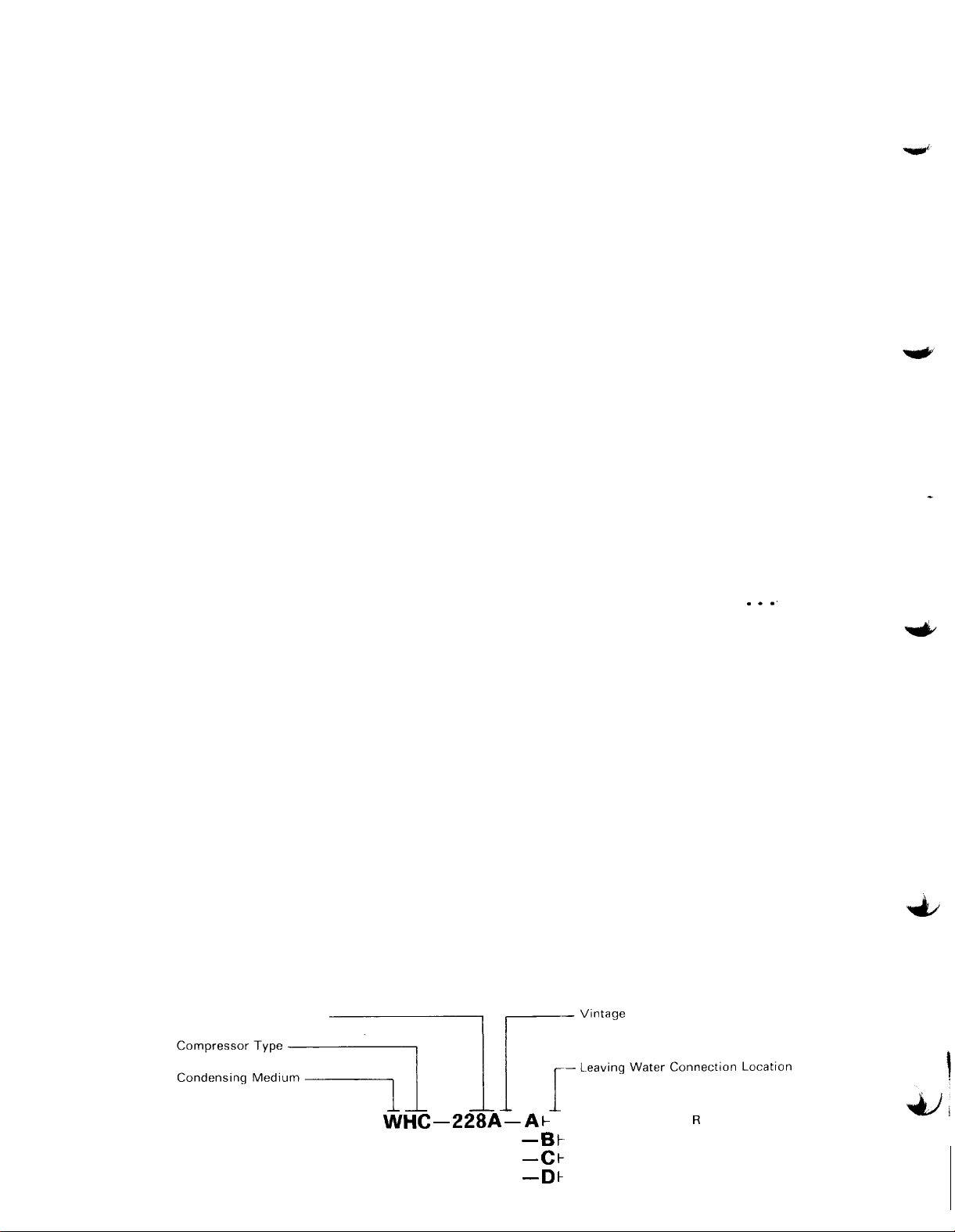
TABLE OF CONTENTS
Controls
...............................................
Sequence of Operation...................................1 5
Set Points
Wiring Diagram
Charging
Dimensional Data
Electrical
Auxiliary Interlocks
Motor Data
Power Wiring
Electronic Control
Operation
Calibration
Evacuation
Leak Tests
Liquid Flow Control
Location
Motor Cooling
Moving and Mounting
Oil System
Physical Data
Pre-Installation
Pre-Startup
Pressure Drop-Evaporator
Pressure Drop-Condenser
Shutdown
Startup
................................................
Trouble Shooting
Vane Control
Warranty Information
Water Piping
Chilled Water
Condenser Water
Oil Cooler
System Schematic
...........................................
......................................
.................................................
.........................................
.............................................
..............................
..13.14
...........................................
.........................................
.......................................
............................................
............................................
................................
.._............3 6
..............................................
......................................
.................................................
..........................................
......................................
.............................................
..........................................
...................................
..ti
............................................
...............................
................................
...............................................
.........................................
..........................................
.....................................
.............................................
..........................................
........................................
............................................
.......................................
..12
..l
6
26,27
37
5
..ll
..4 5
..ll
34
..3 4
40
.3
6
32
3
..3
4
4
..2 4
..4 6
3
...
..19
..4 3
..4 4
..3 7
..2 3
48
...2 9
47
6
9
.lO
7
9
01972
McQuay
Division,
“McQUAY”
Nominal Capacity (Tons)
McQuay -
and “SEASONPAK”
Perfex Inc.
WHC _ 228A _ A t
are registered
NOMENCLATURE
trademarks of
- 6 k
- c k
- D t
Page 2
McQuay Division, Minneapolis, Minnesota.
R.H. CONDENSER, R H. EVAPORATOR
R.H. CONDENSER, L.H. EVAPORATOR
L.H. CONDENSER, R.H. EVAPORATOR
L.H. CONDENSER, L.H. EVAPORATOR
Page 3

INTRODUCTION
McQuay WHC Seasonpak centrifugal water chillers are completely
independent,
water.
The WHC Seasonpak centrifugal chillers are factory
assembled as a complete packaged unit, piped, wired,
automatic refrigeration systems, designed to chill
evacuated,
charged with refrigerant and oil, and performance tested, ready
for installation.
shell and water thru-tube condenser:
Each unit consists of: a flooded refrigerant
a single stage gear driven
centrifugal compressor with a liquid cooled hermetic motor,
and an independent oil pump with reservoir system.
Also
included are manual liquid line shut-off valves, liquid line
trimming valve,
liquid line orifice and discharge line check
valve.
The 115 volt control center supplies power to the oil pump, oil
heaters,
automatic operation of the centrifugal chiller.
and all safety and operating controls for complete
Terminals are
provided for all necessary field interlock wiring between
control panel and unit starter, condenser pump relay, chiller
pump starter,
flow switch and oil cooler solenoid.
PRE-INSTALLATION
I.
GENERAL
installation by qualified personnel only.
Equipment such as this is intended for
As a condition
of the warranty,the equipment start up must be performed
under the supervison of a McQuay Service Representative.
Failure to do so voids the warranty.
INSPECTION
II.
Upon receipt of equipment all items should
be carefully checked against the Bill of Lading to be sure
all crates and cartons have been received.
All units
should be carefully inspected for damage when received.
Shipping damage may cause loss of refrigerant charge and
contamination of system.
If any damage is found it
should be reported to the carrier immediately and a claim
filed for damage.
McQuay,
will not be responsible for
any damage incurred in shipment.
LOCATION
This unit is designed for indoor application and must be
A.
1
located in an area where the surrounding ambient
temperature is 40 F. or above.
A good rule of thumb is
to place units where ambients are at least 5 degrees
above the leaving water temperature.
Page 3
Page 4

LOCATION
Because of the electric control devices, the units should
B.
not be exposed to the weather.
(CONTINUED)
A plastic cover over the
control box is supplied as temporary protection during
transit.
An adequately strong foundation or base must be provided
C.
for mounting the concentrated load of the unit. If
necessary,
additional structural members should be provided
to transfer the weight of the unit to the nearest beams.
Surfaces must be reasonably level.
Adequate free area must be provided around the installed
D.
unit for connections and service.
Allow 14 feet for tube
removal and at least 3 feet around the remainder of the
unit for servicing compressor, oil pump, and controls.
MOVING AND MOUNTING UNIT
MOVING THE UNIT
I.
A.
B.
C.
D.
The McQuay Seasonpak centrifugal chiller is mounted on
heavy wooden skids to protect the unit from accidental
damage and to permit easy handling and moving.
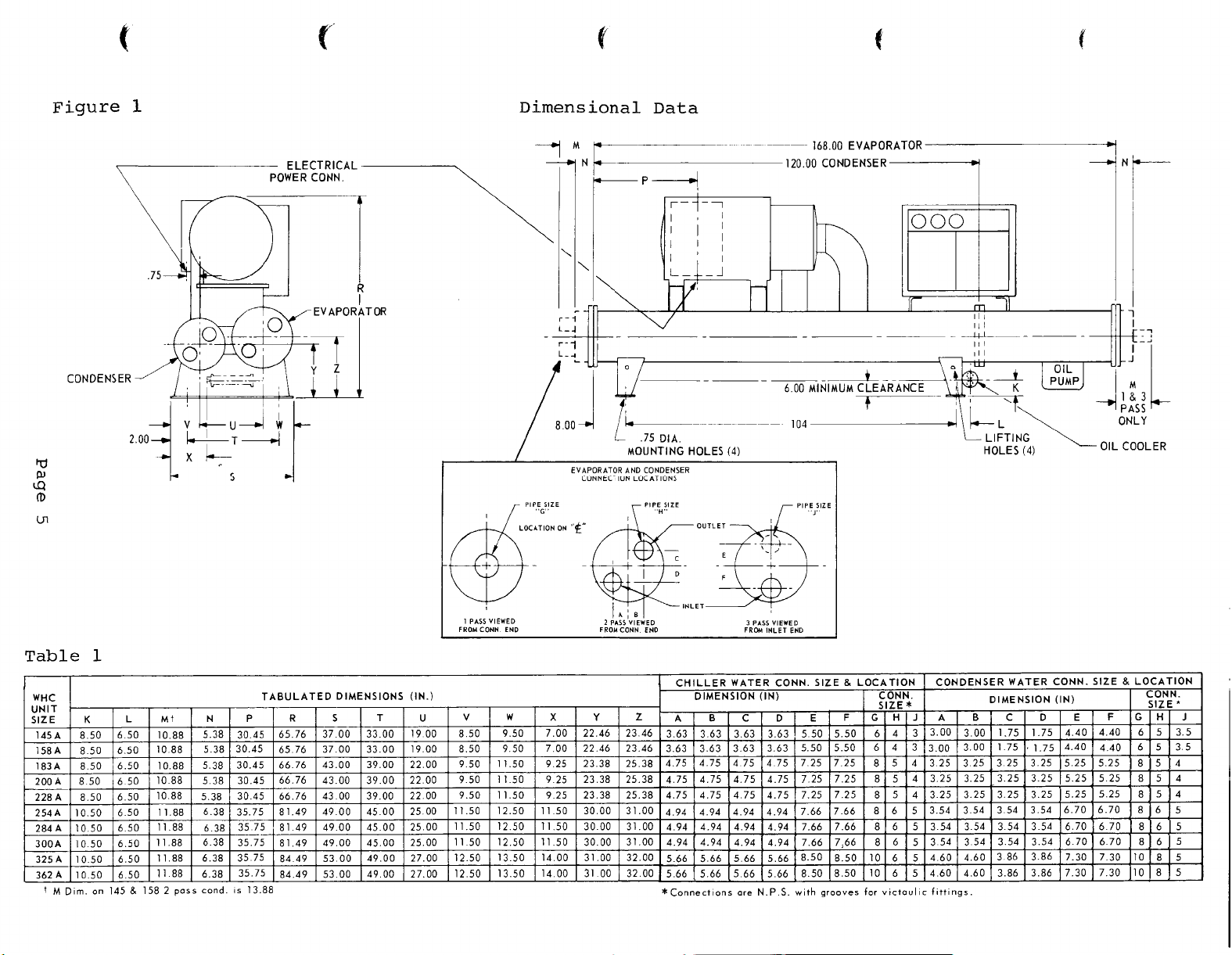
Fig.
1 for physical and mounting information.
See
It is recommended that all moving and handling be
performed with the skids under the unit and that the
skids not be removed until the unit is in the final
location.
When moving the unit,
used under the skids.
dollies or simple rollers can be
In moving always apply pressure
to the base on skids only and not to the piping or
shells.
A long bar helps move the unit easily.
Always avoid dropping the unit.
When rigging the unit attach slings thru holes
provided in the base and always use spreader bars to
protect the control panel,
piping and insulation from
damage.
Do not attach slings to piping or equipment.
in the upright horizontal position at all times.
Move unit
Let
unit down gently when lowering from the trucks or
rollers.
Page 4
Page 5
Page 6

II.
HANDLING
Every model WHC Seasonpak centrifugal chiller is
A.
supplied with a full refrigerant charge.
shipment,
and is isolated by the manual condenser liquid line
valves and discharge line check valve.
Should the unit be damaged allowing the refrigerant
B.
to escape,
equipment area since the refrigerant will displace
the air.
Care should be taken to avoid rough handling or shock
due to dropping the unit.
UNIT FROM ANYTHING OTHER THAN THE BASE.
the charge is contained in the condenser
there may be danger of suffocation in the
Avoid exposing an open flame to refrigerant.
NEVER LIFT,
For
PUSH OR PULL
III.
MOUNTING THE UNIT
A.
The negligible vibration normally encountered with
the Seasonpak centrifugal chiller makes this unit
particularily
installations where the
to the floor if desired.
should be
building structure,
into the structure.
Mount the unit on the rubber
B.
for use under each corner of
level installations or areas
transmission is an important
rubber-in-shear or spring-type isolators are
recommended for maximum vibration isolation from the
building structure.
level unit.
desirable for basement or ground floor
unit
can be bolted directly
The floor construction
such
that the unit will not affect the
or transmit noise and vibration
isolation pads provided
the base.
in which vibration
consideration, optional
Use steel shims if necessary to
WATER PIPING
On a.11 upper
I.
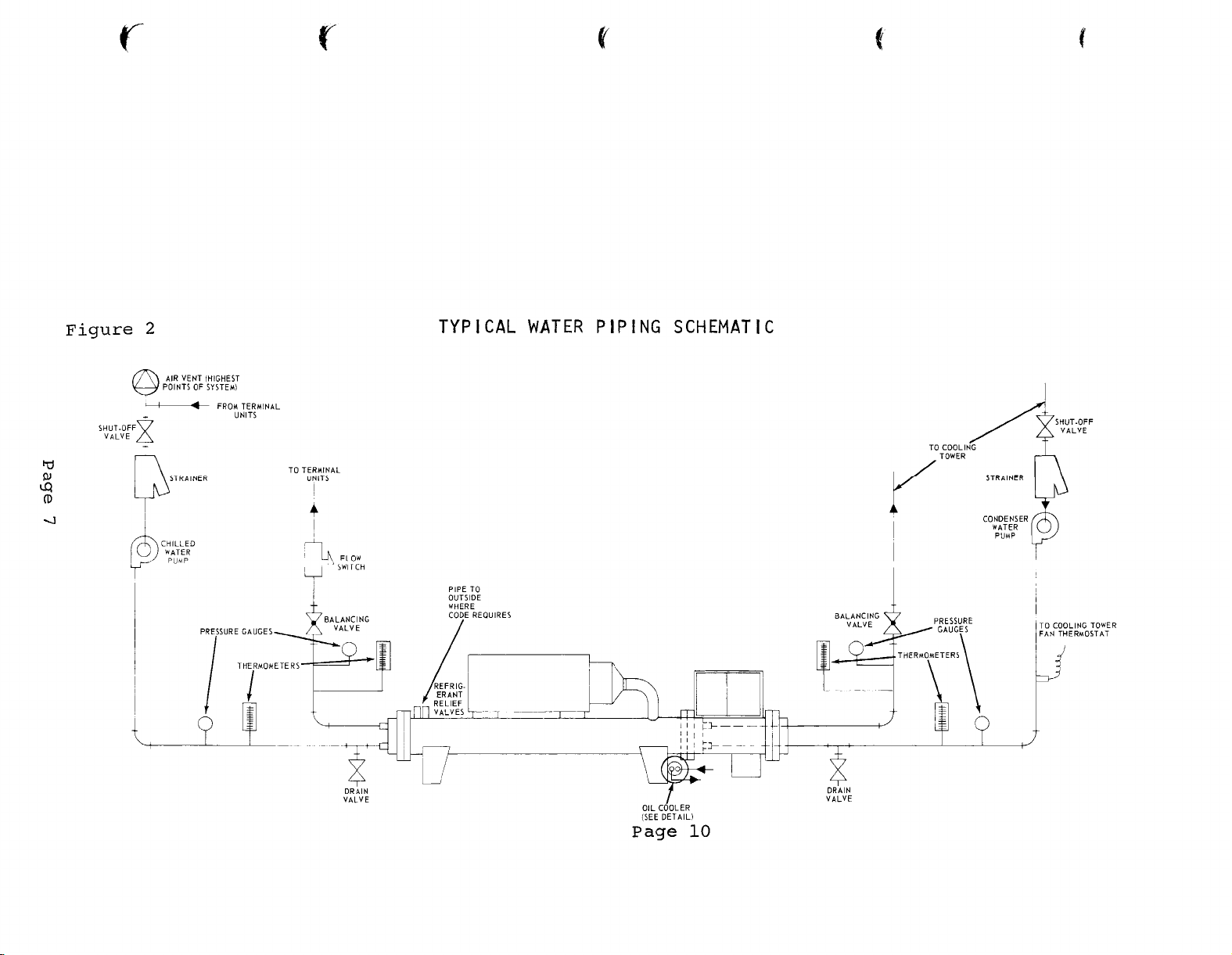
GENERAL CHILLER AND CONDENSER PIPING (See Fig. 2)
When installing water piping follow established practices
A.
and comply with local building and safety codes.
Shut-off valves should be provided at the unit so that
B.
normal servicing of the unit can be accomplished without draining the entire system.
Page 6
Page 7
Page 8

WATER PIPING (CONTINUED) GENERAL
All piping should be installed and supported to
C.
prevent the unit connections from bearing any strain
or weight of the system piping.
Vibration eliminators in all water piping connected to
D.
the unit are recommended to avoid straining the piping
and transmitting pump noise
building structure.
It is recommended that temperature and pressure
E.
indicators be installed within 3 feet of the inlet
and outlet of the shells to aid in the normal checking
and servicing of the unit.
A cleanable-type wire mesh strainer is recommended at
F.
the condenser pump suction and must be provided at
the evaporator pump suction to protect the pump and
shell from foreign matter.
foreign matter is allowed to block evaporator tubes.
and vibration to the
Freeze up can result if
Design the water piping so that it has a minimum
G.
number of changes in elevation.
Include manual or
automatic vent valves at the high points of the water
so
piping,
circuit.
that air can be vented from the water
System pressures can be maintained by using
an expansion tank or a combination pressure relief
and reducing valve.
A preliminary leak check of the water piping should be
H.
made before filling the system.
The water connections are of the grooved Victaulic
I.
type for use with Victaulic couplings.
Matched fittings
must be field provided for the inlet and outlet
connections.
The water inlet is the bottom connection
and the water outlet the top connection on both
evaporator and condenser for all 2 and 3 pass units.
See Table I for chiller and condenser connection sizes.
If the shells must be drained for winter shut-down it
J.
is recommended that an anti-freeze solution be circulated
and drained for positive freeze protection.
All supply and return water boxes for the evaporator
K.
and condenser are provided with two pipe plugs which
can be removed for venting and draining the shells.
Page 8
Page 9

II.
CHILLED WATER PIPING
A.
All chilled water piping should be insulated to
prevent condensation on the lines. If insulation is
not of the self-contained vapor barrier type, it
should be covered with a vapor seal.
not be insulated until completely leak tested. Vent
and drain connections must extend beyond proposed
insulation thickness for accessability.
Piping should
B.
C.
The system cycling thermostat, TC(W) and electronic
vane control EVC are mounted inside the control
console with the sensors mounted in the evaporator
leaving water connection. The low water temp safety
TS(LW),
sheet.
charged capillary tubing when working around the
unit.
before running the unit to be sure that it is firmly
anchored and not rubbing on the frame or any other
component.
The evaporator water boxes can be interchanged end
for end so that the water connections
either end of the unit.
sensors discussed above must be moved to sense the
leaving water temperature from the unit.
gaskets must be used if a change is made.
must be trimmed to conform to block-off baffle
arrangements in the water boxes which vary with the
number of passes in the shell.
sensing bulb is located in the chiller tube
Care should be taken not to kink or break the
It is also advisable to check the cap tube
can be
If this is done the 3
New head
made at
Gaskets
III.
CONDENSER
A.
Water cooled condensers may be piped for well water
applications,
cooling tower.
include a small amount of waste circulating water
and adequate water treatment provided to prevent
build-up of contaminants and scale in condenser tubes
and tower basin.
The condenser water boxes can be interchanged end
B.
for end so that the water connections can be made at
either end of the unit.
trimmed and used if a change is made.
C.
The minimum entering water temperature to the
condenser is 65 F.
cooling tower or condenser bypass or by thermostatic
control of the cooling tower fans,
-
WATER PIPING
or for use in conjunction with a
Cooling tower applications should
New head gaskets must be
This can be accomplished by a
Page 9
Page 10
CONDENSER WATER PIPING
A condenser flow switch is not required and cannot
D.
be wired directly into the interlock circuit. If
used,
a normally closed timer must be used to bypass
the condenser flow switch on start up.
(CONTINUED)
IV.
OIL COOLER WATER PIPING
A minimum of 8 GPM of water at 85 F. or lower
A.
temperature must be provided to the oil cooler to
maintain the oil temperature leaving the cooler at
NPT connection is
a maximum of
110 F.
the inlet and the top
If condensing water is used it is imperative that the
B.
The bottom
NPT connection is the outlet.
1""
1""
water temperature be kept within design limits to keep
oil temperature supply below 110 F.
There is also a
potential problem due to fouling which reduces
effectiveness.
This problem must be recognized and
frequent tube cleaning may be required.
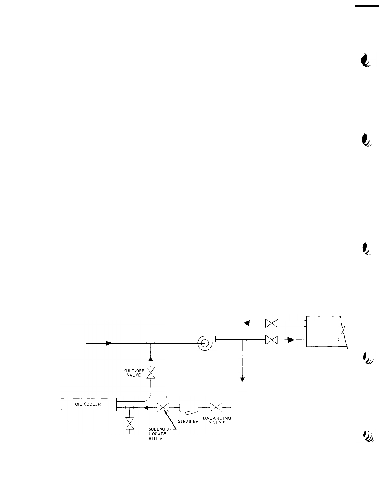
When chilled water is used as the source of water for
C.
the oil cooler it should be piped across the chiller
pump directly to assure full pump pressure across the
oil cooler.
See Figure below.
DRAIN
VALVE
Preferred Oil Cooler Piping
A
A
t’
WITHLN
3FT OF
COOLER
CHILLED WATER
PUMP
EVAPORATOR
Page
10
Page 11
D.
If it is necessary to connect the oil cooler in
parallel with either shell, it is essential that
the
pressure
drop in the line be kept down to assure
adequate flow to the oil cooler. The oil cooler
water pressure drop is 3.5 feet of water at 8 GPM.
E.
City water can also be used as the source of supply.
A flow balance valve should be provided and the
drain line should be trapped to prevent the oil
cooler from draining on the off cycle.
F.
In a.11 cases a strainer with a maximum
l/4"
should be provided at the oil cooler inlet and a
normally closed
must be
provided and wired as shown on the unit
115V.
solenoid valve (water duty)
wiring diagram.
REFRIGERANT VENT PIPING
Both the evaporator and the condenser shells have
A.
pressure relief valves to vent out refrigerant gas
if an unsafe pressure should build up in the shell.
It is recommended that these valves be vented to
the outside to meet local codes.
piping procedure follow ASA
B9-Sec.
For proper vent
12, ASME and
local codes.
ELECTRICAL
mesh
I.
POWER
WIRING
The WHC Seasonpak centrifugal chiller is designed to be
used in conjunction with a separately supplied starter of
the across-the-line,star-delta or auto-transformer type.
The starter and overloads are specifically selected for
application with a specific size Seasonpak centrifugal
chiller.
A.
All field wiring must comply with local, state and
Standard NEMA motor starters are not acceptable.
National Electrical Codes.
All fuses and wiring between disconnect, starter, and
B.
motor must be in accordance with the National Electrical
Code.
The compressor motor is supplied with 6 terminals for
c.
use with across the line, star-delta, or auto-transformer
starters.
When across-the-line or auto-transformer
starters are used terminals l-6, 2-4 and 3-5 must be
jumpered together with terminal straps.
Page 11
Page 12
ELECTRICAL POWER WIRING (CONTINUED)
CARE must be used in wiring leads to compressor motor
D.
terminals to assure that proper phase relationship is
carried through starter to motor.
CONNECTIONS TO THE COMPRESSOR ARE NOT TO BE MADE UNTIL
POWER WIRING HAS BEEN CHECKED AND APPROVED AY AN
AUTHORIZED McQUAY FIELD SERVICE REPRESENTATIVE.
CAUTION: DO NOT TURN MOTOR TERMINAL STUDS WHEN MAKING
POWER CONNECTIONS.
THIS COULD LOOSEN STUD NUTS AND
CAUSE REFRIGERANT LEAKAGE.
The power wiring to the compressor must be in the
E.
proper phase sequence
for correct motor rotation.
With phase sequence of l-2-3 and
Tl-T6,
L2 connected to T2-T4 and L3 connected to T3-T5
the motor will rotate in the proper direction (clockwise when checking in motor sight glass).
and L3 lines at compressor motor junction box.
L2,
F.
EXTENSIVE DAMAGE CAN RESULT IF MACHINE IS ALLOWED TO
RUN IN WRONG DIRECTION.
McQUAY IS NOT RESPONSIBLE
FOR MACHINE DAMAGE CAUSED BY REVERSAL OF POWER PHASE
BY POWER COMPANIES,
ELECTRICIANS OR OTHERS.
NOTE:
Ll
connected to
FINAL
Label
Ll,
II.
CONTROL WIRING
60
A separate source of 115 volt,
cycle power is required
for the Seasonpak centrifugal chiller control circuit.
This circuit is to be fused at 15 amps to protect the
control circuit from overload.
A.B.IMPORTANT
THE DISCONNECT TO THIS CIRCUIT MUST REMAIN
ON AT ALL TIMES TO MAINTAIN PROPER OIL TEMPERATURE IN
THE SEASONPAK CENTRIFUGAL CHILLER TO PREVENT
REFRIGERANT FROM ACCUMULATING IN THE OIL.
ATTACH A LABEL WITH THE ABOVE NOTE TO THE CONTROL
CIRCUIT DISCONNECT SWITCH.
The source of power for the control circuit can be
transformer, if provided, in the unit starter.
The
transformer must be rated at 3 KVA with an inrush
rating of 18 KVA.
If the transformer is used as a
source of power the unit disconnect should also be
marked with the label shown above in Paragraph A.
a
Page 12
Page 13

III.
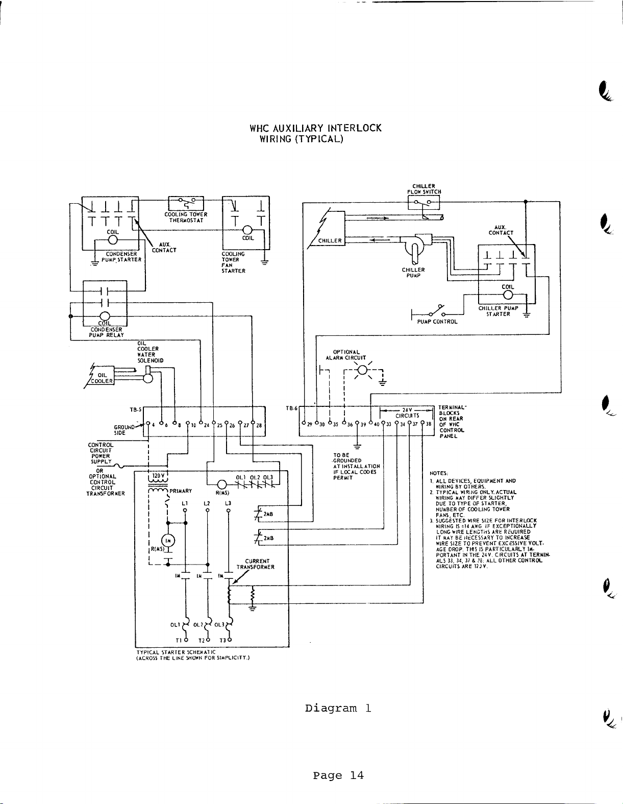
AUXILIARY WIRING
In addition to the power wiring supplied to the unit
control center,
additional interlock wiring is required
and is to be wired directly to terminals provided in
the control center.
size for the amp capacity of the circuit.
Wire Gauge #14 THW is of sufficient
Consult the
auxiliary interlock wiring diagram (Diagram 1) for
detailed wiring information.
A.
Wire the two sets of normally closed contacts (in
unit starter) to terminals 26, 27, and 33, 34 in the
control center.
B.
Add wires from the current transformer provided in,
the unit starter to terminals 37, 38 in the control
center.
C.
Provide a chiller pump interlock to prevent the
compressor from starting until chiller water flow has
been established.
A set of normally open contacts
on the chiller pump starter is required in
conjunction with a flow switch to be wired to
terminals 29, 40, and 30.
D.
Provide a condenser pump relay with 2 sets of
normally open contacts (115 v. coil max. 100 VA
rating),
to start the condenser water pump at the
time the compressor is ready to start and cycle the
condenser pump with the compressor.
control center terminals 24,
28 with a set of normally
Wire coil to
open contacts wired to terminals 24, 25 and the
second set of normally open contacts to start the
condenser water pump.
E.
Wire in the leads from the
oil cooler water solenoid
(115 V. coil) to terminals 8 and 6 in the control
center.
F.
Add interlock wiring between the control center
terminals 25 and 28 and the m&r starter relay in
the unit starter.
G.
Terminals 35 and 36 in the control center can be
wired into a customer supplied and powered alarm
circuit if desired.
H.
Terminal 39 is a ground terminal for the control
panel and should be wired to a suitable ground if
local codes permit.
Page 13
Page 14
Page 15

The necessary operational and safety controls for the McQuay
Seasonpak centrifugal chiller are mounted in the control center
or incorporated in the system.
between the starter, pumps, and unit:
With the interlock wiring
the control circuit is complete
and the system will operate automatically.
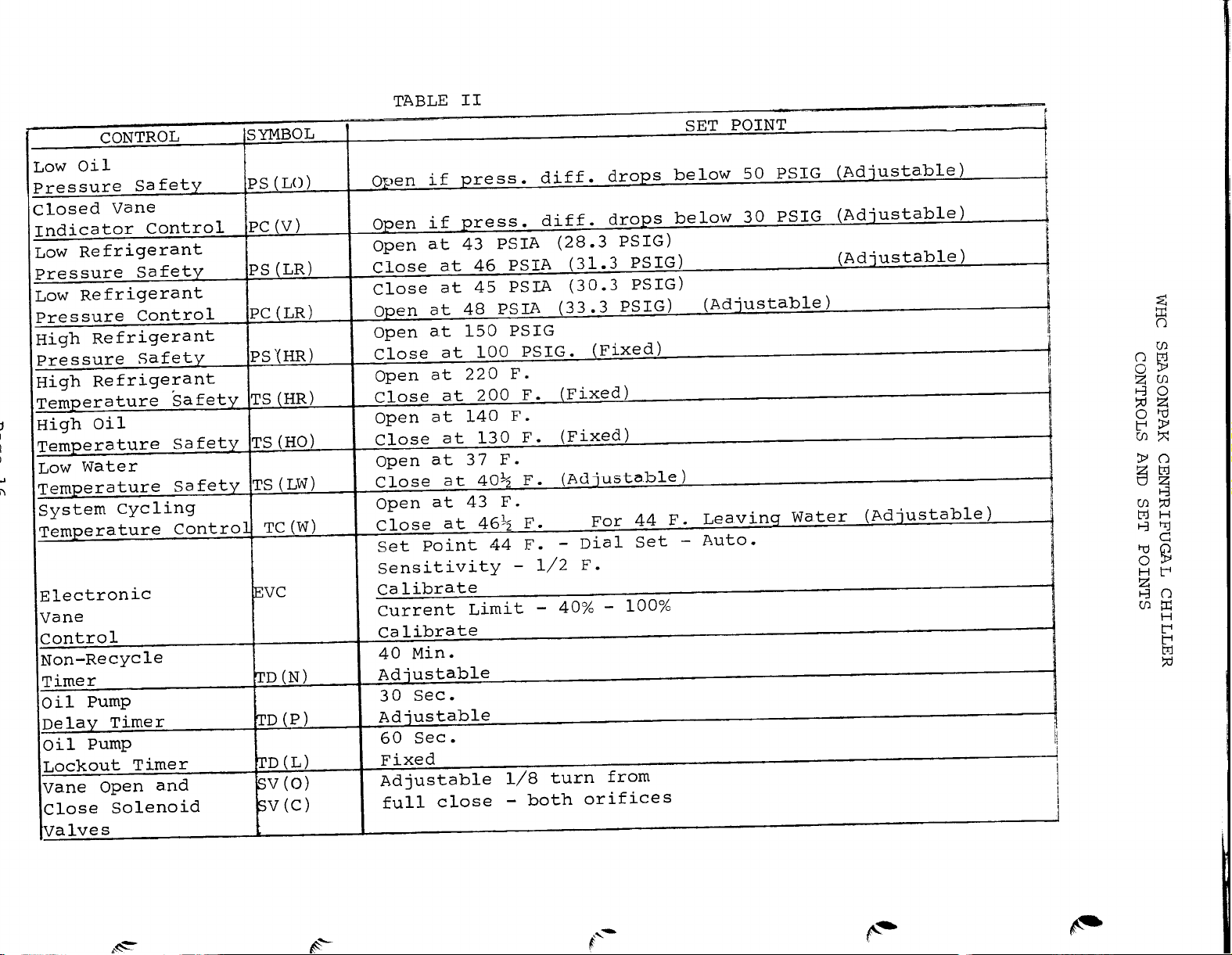
A description of the controls,
control function and set point is
shown in Table II.
A schematic wiring diagram incorporating wire numbers is shown on
P 26
27. The numbers on the left of the
diagram designate
the
&
line numbers as an aid in following the sequence of operation.
With 115 V. power to the control circuit, the system switch
"Off"
and the unit calling for cooling the following sequence
Sl
of operation applies.
I SEQUENCE OF OPERATION (Note: A simplified Sequence Appears
in Catalog 920)
A.
Power is fed thru the normally closed contacts of TD(P) and
energizes the oil sump heater and compressor heater (L. 65).
B.
Power is also fed to transformer,
Tl,
(L.85) energizing the
24V. circuit controlling the vanes and energizing the D.C. motor
relay (L. 82) closing R (T) contacts
C.
Providing all safeties
PS(L0)
and R(T) are made,
PS(HR), PS(LR), TS(HR), TS(HO), TS(LW);
reset switches 2-8 can be pushed energizing
relays R4-R10 and de-energizing lights
l-2(L.52).
LTl-LT7.
D.
With the l-3 contacts of R4-R9 closed,
R3 is energized closing
its contacts 4-6 in the compressor starter circuit (L.25).
E.
If 40 minutes have elapsed since the machine has last started,
Rll
will be de-energized and Rll contacts 1-2 closed (L-21).
F.
By switching Sl to the "on" position, power is now fed thru
TD(L) normally closed-timed open contacts if all interlocks are
closed and above conditions have been met.
G.
The
TD(P)
closed
motor,
H.
-
providing oil pump overload, OL is closed (L.13).
All Ml contacts of the oil pump starter close, starting the
clutch coil is energized closing TD(P) normally
timed open contacts which energizes Ml contactor and
oil pump and energizing the field wired oil cooler solenoid.
Closed vane indicator control, PC(V), will close at 30 PSIG oil
pressure differential (only if vanes are closed).
TD(P)
Page 15
Page 16
Page 17

As the oil pressure builds up the closed vane indicator control,
I.
PC(V),
vanes are closed).
suction pressure,
wired condenser pump relay, R(CP) (L-27).
J.
energized along with the TD(N) motor and
closed-timed open contact of
the machine from starting again for 40 minutes by keeping Rll
energized and
will close at 30 PSIG oil pressure differential (only if
As the oil pressure builds up to 60 PSIG above
PS(L0)
With the closing of Rl contacts 4-6
Rll
contact 1-2 open.
contacts close energizing Rl and the field
TD(N).
(L.59)
Rll
This
non recycle timer prevents
the TD(N) clutch is
thru the normally
When R(CP) is energized,
K-
the motor starter relay, R(MS) (L.27).
L.
The R(MS) normally open contact in the starter energizes the circuit
to the starter,
compressor will now start.
M.
The unit will have started on low load with the vanes closed since
normally closed starter interlock (Terminals 33, 34) will have
energized fast close solenoid
now opens permitting the EVC to control the vanes.
N. Compressor starter normally closed interlock (Terminals 26, 27)
(L.17)
opening the circuit.
up pressure in 60 seconds,TD(L) will open up the compressor circuit
and stop the oil pump.
0.
located in the chiller leaving water to control the compressor
inlet guide vanes. On temperature increase
causing the vanes to open and on temp.decrease
slowly closing the vanes and thereby limiting the volume of gas the
compressor handles.
also opens de-energizing TD(L) and preventing TD(L) from
The electronic vane control (EVC) utilizes an electronic sensor
providing power to the compressor motor. The
If for some reason the oil pump does not build
R(CP) contacts close energizing R2 and
SV(FC).
The normally closed interlock
SV(0)
is energized,
SV(C)
is energized
P.
The electronic vane control (EVC) also receives a signal from a
current transformer, CT,
current reaches 100% of the control set point, the current control
circuit in the EVC overides the temperature control circuit and
prevents the vanes from opening further.
to increase to 105% of the set point the current control energizes
SV(FC)and SV(C).These solenoids direct oil flow to swiftly close
the vanes and thereby limit the unit power.
The low refrigerant pressure vane control
Q.
also override the EVC and put the vanes in fast close as above if
the suction pressure drops to an undesirable low point.
located in the unit starter.
If motor current continues
PC(LR),
Page 17
If the
(L.78) can
Page 18

R.
The above control sequence described in 0, P, and Q will keep
the machine on the line and provide automatic operation down to a
10% load.
of TC(W)
and stop the compressor.
which starts the timing of the
to run for 30 seconds however until
S. The compressor can also be stopped similar to R above by any one
of the six safety controls:
or
PS(L0).
If leaving water temperature drops below the set point
(L.25),
it will open
The
,
de-energize the circuit to
TD(P)
clutch will also be de-energized
TD(P)
motor.
TD(P)
contacts time open.
The oil pump will continue
R(MS)
PS(HR), PS(LR), TS(HR), TS(H0) TS(LW),
If for example,
contacts R4,
light
1-2.
LTl,
de-energes R3 opens R3 contacts 4-6 and closes R3 contact
The R3,
supplied alarm bell if used.
upon pressure reduction,
energizing R4 and consequently R3.
PS(HR)
l-3 and 4-6 and closing R4, 4-5.
opens R4 (L.35) is de-energized opening
This lights warning
1-2 contacts will energize a circuit to a field
Although
PS(HR)
automatically resets
R4 cannot be energized until S2 is reset,
Operation of other safety controls
is similar.
T.
If the oil pressure drops below 50 PSIG differential during
operation,
de-energizing R-10 and lighting LT7.
resets to energize
PS(L0)
contacts (L.25) open stopping the compressor,
S8 must be reset after PS
R10
(L.55). On unit shut down or on
(LO)
operation of safeties in 2 above R2 normally closed contacts 1-2
keep
RlO
energized after PS(LO)opens and reset of S8 is not required.
For detailed control operation see control operation and calibration
P.
As described above,
the machine and the light will indicate the malfunction.
16
.)
an opening of a system safety control will stop
Before
resetting the corresponding reset button the cause of tie malfunction must be located and corrected.
Failure to do so will cause
repeated malfunction and machine damage.
Repeated tripping of a safety should be reported to the McQuay
Service Department and immediately investigated by a qualified
refrigeration service engineer.
PRECHECK FOR INITIAL START UP
After all of the piping and interlock wiring to the unit has been
completed,
up check is to be made per Items A
and all auxiliary components installed a pre-start
-
K below.
See
Appendix B
for
list of instruments and tools suggested for unit check out and
operation. At this point the McQuay Seasonpak Centrifugal Pre-Start
Check List (Form 240284A) must be completed and returned to the
McQuay Service Dept.
Page 18
Page 19

NOTE:
The completed form must be received by the McQuay Service
Department at least two weeks before a McQuay Service Representative
will be sent to the job site for start up.
c
'NOTE:
OF AN AUTHORIZED
I
A.
contactor to make sure it operates freely.
and clamps must be removed from relays and
operate relays,
freely.
compatibility of materials, dirt,
necessary.
at 105% of compressor FLA.
THE INITIAL UNIT START UP MUST BE PERFORMED IN THE PRESENCE
McQUAY
SERVICE REPRESENTATIVE TO VALIDATE WARRANTY.
PRE-START UP
With main disconnect open manually close and open main starter
All shipping wedges
contactors.
Manually
contacts and interlocks to see that they work
Check current carrying contacts and terminals for
and rust and change or clean if
Check the 3 overload relays to make sure they are rated
Check dashpot and piston assemblies
for cleanness and add dashpot fluid per manufactures overload
instructions.
B.
Check all electrical connections in control panel and starter
to be sure they are tight ardprovide qood electrical contact.
Although connections are tightened at the factory they may have
loosened enough in shipment to cause a malfunction.
*
C.
Check and inspect all water piping. Make sure flow direction
is correct and piping is made to correct connection on evaporator,
condenser and oil cooler.
D.
Open all water flow valves to the condenser and evaporator.
E.
Flush the cooling tower and system piping.
pump and manually start condenser pump and cooling tower.
all
piping for leaks.
and
condenser water circuit as well as from the entire water system.
F.
Check pressure drop across evaporator, condenser, oil cooler
and
see that water flow is correct per the design flow rates.
G.
Check the actual line voltage to the unit to make sure it is
the
same as called for on the compressor nameplate within
and
that phase voltage unbalance does not exceed
adequate power supply and capacity is
H.
Make sure all wiring and fuses are of the proper size.
Vent the air from the evaporator
available
Start evaporator
Check
210%
2%.
Verify that
to handle load.
Also
make sure all interlock wiring is completed per McQuay diagrams.
I.
Verify that all mechanical and electrical inspections by code
authorities have been completed.
Make sure all auxiliary load and control equipment is operative
J.
and that an adequate cooling load is available for initial start up.
Page 19
Page 20

K.
Arrange to have qualified maintenance personnel (who will be
in charge of operation of equipment) present at initial start up
for operating instructions.
Upon completion of the above checks, return the Pre-Start check
list (Form
After the above checks have been completed, the unit is ready for
leak testing and control circuit checking before actual start up.
THESE TESTS MUST BE DONE IN THE PRESENCE OF AN AUTHORIZED
SERVICE REPRESENTATIVE.
II
LEAK TESTING
Although the unit underwent two extensive refrigerant leak tests
at the factory and was free of leaks when shipped, leaks could
develop if damaged or mishandled in shipping.
be performed by the start up contractor under supervision of a
McQuay Service Representative.
testing.
240284A)
to the McQuay Service Dept.
See Appendix
A
McQUAY
A leak test must
for details on leak
III
Upon completion of above pre-start up check the control panel must
be checked.
factory before being shipped,
shipping and field interlock wiring circuits, if incorrect,
cause system malfunction.
NOTE:
open.
of oil pump and close the right hand pump return valve
turns from full back-seat position to allow oil drainage from vane
systems.
oil level is in top
The oil pump can be run during control circuit test for a short
period of a time, but the compressor must not be started.
T THIS TIME.
With the control circuit only energized and the unit disconnect
open,
motor starter relay in the unit starter.
CONTROL CIRCUIT CHECKS
Although the unit was completely checked at the McQuay
control settings may change during
could
Before control circuit is energized oil pump valves must be
Open fully all three shut off valves
Open oil shut off valve
l/4
of sight glass).
correct unit operation can be determined by observing the
(#6)
at oil filter.
(#3,
4, and 5) on top
(#4)
(Check that
1
l/2
For initial
terminals W and R on oil pump and tape individually to prevent
possible dead shorting.
Add (2)- 115V lights in parallel with oil cooler solenoid and
to observe simulated oil pump and compressor operation.
part
of test,
temporarily remove 2 wires from
Page
20
R (MS)
Page 21

Clamp ampmeter across heater circuits to check their operation.
A.
With system switch Sl "off"
lights 1-7 and alarm will be
energized when 115 V. power is applied to
-
Reset all safeties
alarm should stay on until last light is
reset.
B.
Warm bulb of
C.
Switch Sl to "on".
D.
TD(P)
clutch should start, closing
should start timing.
E.
TD(P)
motor should start. Ml contactor should pull in and the
TC(W)
above 45 deg.
TD(P)
Heaters should de-energize.
oil cooler solenoid should energize.
F.
Temporarily jumper
PS(L0)
G.
and
Rl
and R(CP) should then energize, close contact
Ll,
Ml on PC(V).
Ll,
Ml and L2, M2 on oil pressure control
and start the condenser pump.
H.
R2 and
R(MS)
should then energize and
the control
contacts.
TD(L)
should quit timing.
circuit.
TD(L)
R (CP)
On star-delta starters there will be approximately an 8 second
delay between starting and running
I.
TD(N)
TD(N)
should time for 40 minutes.
should continue to time independent of status of rest of
contactors.
After initially starting
circuit.
J.
Warm electronic sensor bulb.
EVC should simulate vane opening
by lighting load light on EVC.
K.
Cool electronic sensor bulb.
by lighting unload light on
L.
Drop pressure to suction control line by closing service
(#l)
valve
on top of evaporator and slowly relieving pressure
EVC.
from control line by loosening flare nut.
EVC should simulate vane closing
At 30.3 PSIG,
PC(LR)
contact should close and simulate vane fast closing by lighting
unload light on EVC.
M.
Drop suction
PS(LR)
R(MS)
should open,
and
R(CP).
control line pressure further.
drop out
LT5 should light,
R5
and R3 and de-energize relays
along with the alarm circuit.
At 28.3 PSIG
The oil cooler solenoid and oil pump contactor should remain
energized for 30 sec.
(#l)
and valve
and open valve slowly to raise line pressure.
Retighten flare nut on suction control line
Page 21
Page 22

At 31.3 PSIG
reset
PS(LR)
with S3.
and R(CP).
N.
Raise suction control line pressure to 33.3 PSIG and
should open.
0.
Operate EVC on manual switches and verify operation is correct.
PS(LR)
control should reset.
LT2 should energize, and pull in
It is now possible to
R(MS)
PC(LR)
P.
Check additional controls similar to Item L.
put sensor in ice water.
39%
36 F. and close at
For control circuit check of
Q.
F.
TS(LW)
should open on temp. drop at
PS(HR), TS(HR), TS(H0)
To check
temporarily remove lead from control and reconnect.
and R(T)
Corresponding
TS(LW)
light should light and reset switch should function as in Item L.
R.
Remove jumpers from
PS(L0).
LT7 should light and
R(MS)
should
drop out. Ml contactor and oil cooler solenoid should remain energized
for 30 seconds.
S.
Shut off chiller water pump.
R(MS).
to
NOTE:
IMPORTANT After all above tests have been
This should open the starter circuit
completed
satisfactorily,turn off power and remove all jumper wires used
for above test and re-wire oil pump to correct terminals. Leave
115 V. lights connected for oil pump operational check.
IV OIL PUMP OPERATIONAL CHECK
A.
Make sure all oil pump valves are open - See P.
20
.
B.
With system switch "off"
and/or compressor power disconnect "off",
compressor motor leads disconnected,
energize the unit control
circuit to provide power to heaters in oil pump and compressor.
NOTE:
HEATERS MUST BE ENERGIZED 24 HOURS BEFORE OIL PUMP IS
STARTED TO ASSURE ALL REFRIGERANT HAS BEEN DRIVEN FROM THE OIL.
OIL SHOULD BE HOT (APPROXIMATELY 130 F.) BEFORE TESTING AND
C. Reset safeties as necessary.
D.
Switch control circuit switch
Sl,
to "on"
(TD(W)
bulb must
be in an ambient temperature above set point).
E.
Oil pump should start per sequence of operation and build
llO#
up pressure to
on pump if necessary
F.
PC(V) switch should close at 30 PSI above suction pressure.
above suction.
-
clockwise raises pressure).
(Adjust relief valve
(#12)
Page 22
Page 23

G.
PS(L0)
Unload light should be on until
H.
Set EVC to
I.
Set EVC to unload
J.
K.
Switch Sl to "off"
switch should close at 50 PSI above suction pressure.
PS(L0)
and PC(V) are made.
"load" vanes should open (load light on).
-
vanes should close.
-
oil pump should run for 30 seconds before
(Unload light on)..
TD(P) turns it off.
V INITIAL UNIT START
After the above steps have been completed continue with the
following:
A.
Establish correct water flow to evaporator.
B.
Open up suction,
line valves.
(#l,
discharge and oil pressure
2 and 6).
gauge and control
C. Open up refrigerant liquid line valve
(#7)
for compressor
motor cooling.
D.
Open all liquid line valves (#8-10) between evaporator and
condenser.
E.
Check that all oil line valves
(#3,
4, 5 and 6) are open, and
that an adequate supply of hot oil is available.
F.
Check all auxiliary equipment (cooling tower cooling-load,
pumps,
G.
H.
I.
diagram in cover.
J.
oil pressure to build up oil and start compressor.
"Off"
Rotation must be clockwise from motor end.
change phase wiring if rotation is incorrect.
fans and air handlers) to be sure it is operative.
Set EVC at"unload"
for assured closed vane start.
Open oil cooler water valves.
Connect up power leads at compressor motor junction box per
JOG MACHINE
BE SURE PHASE IS CORRECT.
-
momentarily switch Sl to "on" long enough for
SEE P. 12
Switch
and check compressor rotation thru bulls eyes in compressor.
Turn off power and
Repeat if
necessary.
.
Sl
to
Page 23
Page 24

K.
After correct rotation has been established and the TD(N)
control has timed thru its 40 minute cycle the machine can
Sl
be restarted by switching
to "on".
CAUTION:
VI .
INITIAL UNIT OPERATION
Manually shut down unit if any malfunction is noted.
When initial start is satisfactory observe the following during
the
first few minutes of operation.
Adequate oil pressure
A.
B.
Liquid refrigerant to motor for cooling.
-
110 PSI above suction.
Sense temperature
drop across motor cooling orifice plate.
Water flow to oil cooler is sufficient and oil temp. to
C.
oil
bearings remains below 110 F. at outlet of
D.
Oil level
E.
No unusual noise or vibration.
F.
With EVC current control set at 100% set manual switch at
"Auto
fast,
"
and observe loading of machine. If vanes open too
adjust vane speed needle valve (See Control Operation and
Calibration (P.
-
top
40 ).
l/2
of sight glass.
cooler.
G. When machine is fully loaded check to be sure the temperatures
entering and leaving the evaporator and condenser are within
design limits,and that amperage and voltage are correct per load.
H.
Adjust EVC as needed per procedure outlined in Control Operation
and Calibration (P. 40
After the machine has been jogged and correct rotation determined,
I.
).
the motor terminals and exposed bare wire must be thermally insulated
with insulating tape provided with the unit.
This is necessary to
prevent moisture from condensing on the terminals during operation
which could cause current leakage and in severe cases a direct short.
IT IS EXTREMELY IMPORTANT THAT TERMINALS ARE PROPERLY INSULATED BEFORE
THE UNIT IS PUT INTO OPERATION.
SYSTEM OPERATION
I
OIL SYSTEM
The oil system for this unit is designed with a dual function; to
provide lubrication to the compressor bearings and provide oil
for the hydraulic vane control system. Figure 3 shows the complete
oil system with figures 4A and 4B and 5 showing in detail the
vane control system.
Page 24
Page 25

Page 26

Page 27

Page 28

A.
LUBRICATION SYSTEM
1.
Oil Pump
The major component of the oil system is an oil pump and
motor assembly operating at 115 V.
oil pump located in the oil reservoir also drives a centrifugal
oil separator which removes the refrigerant vapor from the oil
and returns it thru a service valve
The oil differential pressure, above suction, can be controlled
by adjusting the relief valve
assembly.
be adjusted upward by clockwise rotation.
operation pressure should be 110 PSIG above suction.
heater located in the bottom of the oil reservoir is energized
during the compressor off cycle and is used to provide warm
F)
(135
must be
the oil.
2.
refrigerant free oil on unit start up. The oil heater
enegized
Oil Cooler
and
Reservoir Assembly.
By using a
24 hours before start up to adequately heat
The direct coupled
(#5)
to the compressor.
(#12)
on top of the oil pump
l/4"
Allen head wrench the pressure can
During normal
An oil
The oil is pumped thru a service valve
to a water cooled oil cooler located on the unit.
oil temperature is lowered sufficiently to provide oil of
the proper temperature (90
3.
Oil Filter
The oil is then pumped to the oil filter which is an integral
part of the compressor housing.
micron cartridge that should be changed when the difference
between oil pressure and suction pressure (oil gauge reading)
drops to 60 PSIG.
To change the oil filter,
on the oil reservoir cover and close the
(#6)
on the oil filter.
before removing cover and replacing core.
filter outlet prevents losing pressure from compressor.)
After assembly vent air from oil lines before restarting
machine.
From the oil filter,
oil reservoir as well as the 2 low speed and 3 high speed
bearings thru internally drilled passages in the compressor
housing.
supplies adequate lubrication for 3 times the spindown time
during normal operation and in the event of oil pressure loss
due to power failure,
The spring loaded piston in the spindown reservoir
oil is supplied to the safety spindown
oil pump overload or oil pump failure.
-
110 F) to the bearings.
The filter contains a 10
front seat the outlet valve
Purge the oil supply lines
(#3)
in the oil pump
Here the
l/4"
shut off valve
(A check valve on
(#3)
slowly
Page 28
Page 29

4.
5.
Gear Lubrication
The oil drains from the bearings
into the gear housing and is returned to the oil pump
thru a full flow return line.
is in this line,
#3
valves
and 5 permit complete isolation of the oil
pump and reservoir.
at the oil pump reservoir and with
When the high pressure oil drains
A shut off valve
(#4)
from the bearings into the low pressure gear cavity it
immediately flashes into a fine oil mist, and releases
any refrigerant which may have been entrained in the
oil.
the gears.
This fine oil mist provides the lubrication for
A gear case heater is provided in the
compressor housing to prevent refrigerant collection
in the oil on the off cycle.
Oil Charging
The oil level during operation should always be visible
in the sight glass (normally at
l/2
level).
If necessary
to add oil use only McQuay oil
No.
921-238031X (Suniso
charging pump at valve
4G
S) and charge with an oil
(#13)
on the bottom of the oil
reservoir.
IS
0 OTHER OIL
NOTE:
Fill only to top
SUITABLE/
l/4
of sight glass on
Over charging can cause oil loss to the refrigerant system.
B.
VANE
CONTROL SYSTEM
The capacity of the unit is controlled by inlet guide vanes
located at the impellor eye.
The vanes are positioned by a
piston (Figures 4A and 4B) which moves to open or close the
vanes,
oil is supplied.
depending on which side of the vane control piston
The oil flow to the piston is controlled by
the operation of a 4-way normally open solenoid valve (coils
SV(S)
coil
and
SV(0))
SV(FC).
and a 2-way normally closed solenoid valve,
When a coil in the 4-way solenoid valve is energized, the flow
is from the port,
outlet.
inlet,
When a coil is de-energized the flow is from the
thru the solenoid valve and thru the port.
thru the adjustable orifice and to the
(See Fig. 4A and 4B).
Page 29
Page 30

Page 31

Page 32

When the electronic controls call for vane opening and
increased capacity the oil flow is as shown in Figure 4A
(with
SV(O)
energized
SV(S)
and
SV(FC)
de-energized). When
the electronic controls call for vane closing and reduced
capacity the oil flow is as shown in Fig. 4B (with
energized and
SV(0)
and
SV(FC)
de-energized).
SV(C)
When the electronic sensor indicates leaving chilled water
temperature has reached design conditions, all solenoids
will be de-energized,
full oil pressure is supplied to both
sides of the piston and the vanes will hold.
If the control circuit calls for fast vane closing as described
in the sequence of operation SV(C) and
SV(0)
Fig. 5.
will be de-energized and oil flow will be as shown in
Under this condition the metering valves A and B are
SV(FC)
will be energized,
by-passed speeding the oil flow and closing the vanes in
approximately 15 seconds.
When the vanes are completely closed, the vane closed switch
port is uncovered and with positive oil pressure the PC(V)
differential switch closes.
This assures a vane closed start.
The speed of the vanes is controlled during normal opening
and closing by two needle metering valves (adjustable orifices
B)
A and
in the oil drain line (See Figs. 4A and 4B).
needle valves are factory set to provide a minimum of
from full closed to full open vanes.
Closing the needle valves slightly slows the vanes down.
The correct speed should be slow enough to prevent hunting
and over controlling.
These needle metering valves are not
in the system during fast close and do not affect the fast
cbse
speed.
II
LIQUID FLOW CONTROL
The sub-cooled liquid refrigerant leaving the condenser is
expanded thru a liquid line orifice and equalizer system
and enters the distributor in the evaporator.
The
distributor assures uniform refrigerant distribution thru
out the full length of the evaporator.
The correct
refrigerant flow to the evaporator is maintained under all
conditions of operation by an automatic trimming valve
The automatic trimming valve is factory preset
to maintain
the correct level of refrigerant in the evaporator and does
not require field adjustment.
These
1
minute
(#ll).
Page 32
Page 33

Page 34

Shut off valves (#8-10) are provided in the liquid line to enable
isolation of condenser for pumpdown of the unit.
III
MOTOR COOLING SYSTEM
The hermetic motor is cooled by liquid refrigerant from the
condenser outlet. The sub-cooled liquid passed thru a shut off
valve
(#7),
check valve,and filter drier up to an orifice plate
mounted on the compressor housing.
Upon flashing into the motor housing,
rotor and
stator.
The gas and excess liquid is drained back
the refrigerant cools the
into the evaporator thru separate drains in compressor housing.
IV ELECTRONIC CONTROL OPERATION
A solid state combination electronic temperature control and motor
load control (EVC) is used to regulate the cooler leaving water
temperature and control the current draw of the motor.
A.
ELECTRONIC TEMPERATURE CONTROL
An electronic sensor located in the leaving chilled water changes
resistance with water temperature and sends a signal to a bridge
circuit in the electronic
temperature
control.
This signal is
amplified by the control module and is used to actuate the solid
state switches.
The solid state switches operate the coils of
the 4 way oil solenoid to open and close the vanes as described
under Vane Control.
The electronic temperature control contains a selector switch which
permits manual operation of the inlet guide vanes and overrides
the signal circuit.
"Auto".
To manually close vanes switch to "unload" (lower
and to manually open vanes switch to "load"
There is also a
position.
This switch should be set at "Auto" except when used
"hold" position which holds vanes in existing
During normal operation switch should be in
load)
(higher load).
to manually control vanes when servicing unit.
The electronic temperature control utilizes integral action to
provide a very precise control of leaving chilled water
temperature.
It eliminates the throttling range and feedback circuits usually
needed with this type of control.
With integral action the "on"
time of the load or unload switch is dependent upon the difference
between the set point and the leaving chilled water temperature.
As the difference between the set point and the control point
decreases,
the on time (either load or unload) becomes shorter.
The load status is shown by a red indicator light and the unload
status by a green indicator light for ease of service.
Page 34
Page 35

The solid state electronic temperature control is calibrated
at the factory but it should be checked for recalibration.
See Appendix C for calibration and adjustment.
B.
MOTOR LOAD CONTROL
The function of the motor load control circuit in the EVC is to
prevent the machine from operating at a higher amp rating than
design.
system for the compressor motor which limits the current to the
motor at any selected valve from 40% to 100% of full load.
A window type current transformer (CT) is located on one of the
motor leads in the starter and gives a secondary current which
varies with load.
transformer secondary to produce a voltage signal proportional
to load,
the voltage signal should be between
This voltage signal is used to activate solid state switches
in the EVC.
the vanes in a "hold" position.
to increase to
will go into fast close to prevent a further power increase.
If either the 100% or 105% switch is activated a "current control"
light is energized to indicate that the override control is in
operation.
The motor load control is a two stage override protection
A resistance load is added to the current
which operates the motor load control. At full load
.45
and
When the motor current reaches 100% a switch puts
If the motor current continues
105%,
another switch will close and the vanes
.55
volts.
The motor load control remains in control of the machine only
as long as the compressor attempts to deliver more than 100%
of full load.
under any condition when needed.
the position of the vane selector
"Load", etc.
The motor load control contains a
with
power input of the machine at any point between 40 and
thus limiting demand charges.
If, for example,
load amp (FLA) rating is 265 amps, the unit will go into "hold"
at 159 amps
(.60
To calibrate the motor load control see Appendix C.
a range of 40% to 100%.
x 1.05 x 265).
It will override the electronic temperature control
It operates independently of
This permits setting the maximum
this switch is set at 60% and the chiller full
(.60
x 1.0 x 265) and "fast
switch,
percent current limit switch
whether,
close"
at 167 amps
"Auto", "Hold",
lOO%,
Page 35
Page 36

I.
LEAK TESTING
APPENDIX A
The unit
A.
start up, to
should be completely leak tested before initial
check for leaks which may have resulted from
shipping damage. The presence of refrigerant oil on or
near the unit may indicate a leak and adjacent areas should
be carefully checked.
B.
The refrigerant charge shipped with the unit will provide
a positive pressure for this test.
is isolated in the condenser.
Crack one condenser shut off
During shipment the charge
valve and allow enough. refrigerant to enter the evaporator
to build up pressure to approximately 60 psig. and immediately
close valve.As a general rule of thumb this pressure should
be approximately 10 PSIG below the corresponding saturation
pressure at ambient temperature.
C.
With an electronic leak detector carefully check all
brazed joints,pipe connections,
"Victaulic" connections and
control line flare connections for leaks.
D.
If leaks are found they must be repaired.
Leaks in the
evaporator circuit, liquid lines, control lines, etc., can
be easily repaired without removing charge since the unit
is shipped pumped down with charge isolated in the condenser.
II.
E.
After any leak is repaired retest by building up pressure
in the circuit by bleeding a slight amount of refrigerant
from the condenser as in Item B above.
If no leaks are found
on recheck,unit is ready for evacuation.
EVACUATION
To evacuate evaporator circuit keep valves at condenser
(#7,
8 and 9) and oil pump
at evaporator
and condenser
(#l0)
and gauge line valves on top of evaporator
(#l
and 2) should be open.
(#3,
4, and 5) closed.
Valve
Remove existing cores in filter drier in liquid line and
install new cores.
Evacuate by attaching one or more lines from vacuum pump to
valves on bottom of evaporator and to
evaporator liquid line valve
(#l0).
l/4"
fittings on
Page 36
Page 37

Continue evacuation until a reading of 1000 microns (1 millimeter)
or less is obtained and maintained for a minimum of 15 minutes
after the vacuum line is closed.
An electronic or micron gauge
should be connected at the unit to accurately determine the
correct unit vacuum.
If the vacuum pump is incapable of pulling down to 1 millimeter,
a triple evacuation can be used.
inches of mercury vacuum,
add a small amount of refrigerant 12
Pull down to approximately 29
vapor to build up to a positive pressure and pull down to 29
inches.
Repeat 3 times.
Charging
After evacuation, refrigerant
liquid line,
shut off valves at condenser
-
12 charge is to be added. Open up
and allow pressure to
equalize in evaporator and condenser.
If some charge has been lost due to a leak it will
be necessary
to trim charge with unit running.
Note
This additional charge should not be added at this time.
before charging can
preliminary pre-start up checks (P
continue.
)
Complete
After machine has been initially jogged and started per sequence
outlined and additional charge can be added.
THE UNIT MUST BE
OPERATING NORMALLY WITH OIL PUMP RUNNING, WATER FLOW TO CHILLER
AND CONDENSER, AMPS AND VOLTS NORMAL, AND LEAVING CHILLED WATER
TEMPERATURE AND SUCTION PRESSURE ABOVE
FREEZING
.
CAUTION
DO
NOT
LIQUID CHARGE OR RUN UNIT (UNDER ANY
CONDITION)IF
SYSTEM
PRESSURE IS LOWER THAN 30 PSIG.
Connect the refrigerant charging line to the service valve on
bottom of evaporator and charge with R-12 vapor.
The unit is
adequately charged when suction superheat is 2-4 degrees at
full load operation.
UNIT SHUTDOWN
During winter or extended shutdown special precaution should be
taken to prevent possible unit damage.
Page 37
Page 38

A.
water in the chiller,
If the machine will be exposed to freezing conditions all
condenser and oil cooler circuits must be
drained.
This can best be done by disconnecting Victaulic
connection at water boxes and opening vent and drain connection
on water boxes.
-
CAUTION
tubes,
since it is possible that water could hang up in the
the only sure way of removing all water and avoiding
freeze up is to circulate anti-freeze solution thru the tubes,
as well as oil cooler.
Leave drains and vents open until system is refilled.
B.
To prevent accidental start-up of unit during shutdown
cycle open compressor disconnect
and remove fuses from disconnect.
NOTE:
starter,
heaters.
prevent absorption of refrigerant by the oil.
prevent accidental start up,
If control circuit power is provided by transformer in
the disconnect must be left on to provide power to oil
It is important to keep the oil heater energized to
In this case, to
position system switch
Sl
to "off"
and remove R-3 relay.
PUMPDOWN
It is possible to make repairs or replacements on compressors,
controls,
liquid lines, etc.
if necessary without losing the
refrigerant charge by pumping the unit down and isolating the
charge in the condenser.
If it is necessary to pump the system
down use extreme caution to prevent freeze up of the chiller.
CAUTION:
chiller while unit is in pumpdown cycle.
Be sure that full water flow is maintained thru the
Use the following
procedure to pumpdown:
1.
Close liquid line valves at condenser
(#7,
8 and 9).
2.
Jumper
from
3.
PC(LR).
With water flow thru the chiller and condenser, start
PS(LR)
control and temporarily disconnect wire #150
compressor.
4.
Operate unit until suction pressure stabilizes at
approximately 20-25 PSIG.
5.
Operate unit at this point for approximately 2 minutes and
then turn off.
Page 38
Page 39

The discharge line check valve along with the condenser liquid
line valves will isolate the major portion of the charge in the
condenser. Purge remaining gas pressure from evaporator circuit
before working on system.
Approximately 40-60 lbs. of refrigerant
12 will be lost depending on the completeness of the pumpdown.
APPENDIX B
TOOLS AND EQUIPMENT
The following tools,
equipment and instruments are useful in
servicing and checking the unit.
1.
Electronic leak detector (preferred) or halide torch.
2.
Portable high vacuum pump (capacity at least 3 CFM recommended).
3.
Refrigerant charging lines and equipment (gauges, scale,
-
Refrigerant
4.
Refrigeration servicemans hand tools (wrenches, screwdriver,
etc.).
5.
Volt- ohmeter (voltage scale
Vacuum tube voltmeter (VTVM).
6.
7.
Clamp on ammeter (up to 750 amp scale).
Thermometers (4
8.
Water pressure gauges or manometer.
9.
12 etc.).
-
minimum of 2) (2 deg. increments).
to 480 volts).
10.
11.
Oil charging pump suitable to pump against 70 psi pressure.
Phase sequence meter.
Page 39
Page 40

APPENDIX C
I.
SOLID STATE COMBINATION ELECTRONIC TEMPERATURE AND MOTOR
LOAD CONTROL CALIBRATION
The following procedure applies to the Honeywell Centrifugal
Chiller Control
A.
GENERAL
While the basic function of the Centrigual Chiller Control is
to maintain the temperature of the chilled water at the
control point setting by modulating the compressor vanes,
its protective function of limiting excessive current draw
by the compressor drive motor is very important.
current calibration must be done first to provide protection
during temperature calibration or other testings.
W901A
only.
(EVC).
Therefore,
CAUTION:
made while the machine is running.
Set control switches as shown in the startup column of
Table 1.
Adjustment and Calibration of the control must be
I
Manual Position Switch
% Current Control
Control Point
Current Calibration
Temperature Calibration
STARTUP
Close (Unload)
100%
Center of Travel Desired Chilled
(Vertical)
Full Clockwise
Center of Rotation
NORMAL
RUNNING POSITION
Auto
Desired
(100% or less)
Water Temperature
Leave at Position
Determined at
Start-Up
Leave at Position
Determined at
Calibration
Percentage
Page 40
Page 41

B.
CALIBRATE FOR CURRENT
This calibration procedure adjusts the current control section
of the control to the current input signal at terminals A-B.
This signal must be
.50 2 .20
VAC when motor load is 100% of
rated current.
When the above signal has been provided, adjust the CURRENT
CALIBRATION control ccw until current control light just comes
on.
NOTE:
Calibration at 100% automatically calibrates for current
control action at 105%.
CURRENT INPUT SIGNAL TO TERMINALS A-B
(MOTOR
LOAD
AT 100% OF
RATED CURRENT.)
This signal comes from a current transformer and shunt resistor
normally supplied as part of the compressor motor starter.
The
transformer and resistor must be sized, along with a specified
size and length of two-wire lead,
to provide a nominal
0.5 volts
rms to terminals A-B of the control.
CAUTION:
5 volts ac.
GROUNDING NOTE:
Maximum allowable voltage to terminals A-B is
Ground at current transformer only, NOT at
terminals A-B.
CURRENT CONTROL SYSTEM OPERATES AS FOLLOWS:
a.
When the compressor drive motor current rises to 100%
of its rated value,the current control system prevents
further opening of the vanes.
If compressor motor current reaches 105%
b.
(+O, -2)
the
vanes drive toward the closed position until the current
drops to 100%
+l.
(The vanes can still be driven closed
by the temperature control.)
When the compressor current falls to 95%
C.
its full value,
the device returns to full temperature
(+2,
-0) of
control.
Check the preceeding by using the manual position switch to
change compressor load,
After checking,
return the selector switch to AUTO.
then look for proper vane action.
The
device is now calibrated for current.
Page 41
Page 42

C. CALIBRATE FOR TEMPERATURE
Set the manual switch in the AUTO position.
1.
Operate the system until the chilled water temperature
2.
reaches 45 deg. F. For accurate control calibration
the temperature sensing bulb must be maintained at a
constant temperature which can be accurately measured.
Set the control point to mid position (pointer vertical).
3.
Adjust the temperature calibration potentiometer to
4.
achieve a null condition (no vane
Because of the "pecking"
control section, (integral action control) the device is
in a null condition only after a minimum of 45 seconds
with no signal to either load or unload.
The device is now calibrated for 45 deg.
5.
water temperature.
movement)
.
action of the temperature
F. +
1 deg. F.
NOTE:
Page 42
Page 43

Page 44

Page 45

Page 46

Page 47

APPENDIX E
PHYSICAL DATA
WHC
UNIT
SIZE
145A
158~
183A
200A
228A
254111
284A
300A
325A
362~
OIL
CHARGE
GALLONS)
(
4
4
4
4
4
7
7
7
7
7
-r
COOLER
AREA TO
I
3E INSULATE1
(FT2)
66
66
83
83
83
92
92
92
109
109
COND.*PUMP
DOWN CAP.
(LBS.-R-12)
396
396
548
522
492
926
886
866
827
769
RELIEF VALVE
SETTING
(PSI)
VAP.
150
150
150
150
150
150
150
150
150
150
COND
180
180
180
180
180
180
180
180
180
180
*Based on 80% of condenser volume and liquid R-12 at 100 F.
WARRANTY RETURN
.
Material may not be returned except by permission of authorized
factory service personnel of McQUAY Division McQUAY-PERFEX INC.
at Minneapolis, Minnesota. A "Return Goods"
to be included with the returned material.
tag will be sent
Enter the
information as called for on the tag in order to expedite
handling at our factories and prompt issuance of credits.
All parts shall be returned to the McQUAY factory, designated
on the
"Return Goods" tag,
transportation charges prepaid.
The return of the part does not constitute an order for
replacement.
through your nearest McQUAY Representative.
include part number,
Therefore,
model number and serial number of the
a purchase order must be entered
The order should
unit involved.
Following our personal inspection of the returned part and if it
is
determined that the failure is due
workmanship,
credit will be issued on
to
faulty material or
customer's purchase order.
REPLACEMENT PARTS
When writing to McQUAY for service
the model number and serial number Of
serial plate,
required,
attached to the unit.
mention the date of installation of the unit and date
replacement parts, refer to
Or
the unit as stamped on the
If replacement parts are
of failure,along with an explanation of the malfunctions and a
description of the replacement parts required.
Page 47
Page 48

APPENDIX F
TROUBLE SHOOTING
As an aid to servicing your WHC Seasonpak centrifugal chiller
several trouble shooting charts have been prepared.
The trouble
shooting should only be performed by a qualified refrigeration
service man.
If additional information is required, call your
McQuay Service Representative.
The following steps should be taken prior to attempting any service
on the control center:
Check wiring diagram so that you understand the operation of
1.
the Seasonpak,
Before investigating trouble in the control center, check for
2.
centrifugal chiller.
burned out light bulbs by testing across the appropriate ter-
minals.
even though the system switch is off.
Caution
-
the panel is always partially energized
If it is necessary to
de-energize the complete panel,including crankcase heaters,
pull main disconnect.
3.
Check lights and compare with the trouble chart. The possible
of
trouble area
the panel can then be easily isolated.
This chart is merely a quick indication of possible major trouble
spots in the panel or unit.
By comparing the indicator lights
with the unit wiring diagram,additional comparisons can be made.
It is important to have a qualified control panel electrician
service this panel. Unqualified tampering with the controls can
cause serious damage to equipment and void the warranty.
WARNING
Warranty is voided if wiring is not in accordance with specifica-
tions.
or overload
A blown fuse or tripped protector indicates a short ground
-
before replacing a fuse or re-starting compressor,
the trouble must be found and corrected.
Page 48
Page 49

Page 50

Page 51

Page 52

 Loading...