

Page 1
Installation and Maintenance IM-708
Self-contained Air Conditioning System
Type SWP Vintage Sizes 18D thru 95D, 105E
MEA
Group: Applied Systems
Part Number: IM708
Date: February 2002
368-93-E
© 2001 McQuay International
Page 2

Table of Contents
Introduction
General Description . . . . . . . . . . . . . . . . . . . . . . . . . . . . . . . . . . . . 3
Inspection. . . . . . . . . . . . . . . . . . . . . . . . . . . . . . . . . . . . . . . . . . . . . 3
Nomenclature . . . . . . . . . . . . . . . . . . . . . . . . . . . . . . . . . . . . . . . . . 3
SWP-055-D . . . . . . . . . . . . . . . . . . . . . . . . . . . . . . . . . . . . . . . . . . . 3
. . . . . . . . . . . . . . . . . . . . . . . . . . . . . . . . . . 3
Installation . . . . . . . . . . . . . . . . . . . . . . . . . . . . . . . . 4
Handling . . . . . . . . . . . . . . . . . . . . . . . . . . . . . . . . . . . . . . . . . . . . . 4
Vibration Isolators . . . . . . . . . . . . . . . . . . . . . . . . . . . . . . . . . . . . . . 4
Setting Factory Supplied Plenum. . . . . . . . . . . . . . . . . . . . . . . . . . . 4
Location/Service Access . . . . . . . . . . . . . . . . . . . . . . . . . . . . . . . . . 4
Removal of Shipping Restraints . . . . . . . . . . . . . . . . . . . . . . . . . . . 4
Refrigerant Piping . . . . . . . . . . . . . . . . . . . . . . . . . . 5
Pressure Relief Valves . . . . . . . . . . . . . . . . . . . . . . . . . . . . . . . . . . 5
Water Connections . . . . . . . . . . . . . . . . . . . . . . . . . 6
General . . . . . . . . . . . . . . . . . . . . . . . . . . . . . . . . . . . . . . . . . . . . . . 6
Condenser Piping . . . . . . . . . . . . . . . . . . . . . . . . . . . . . . . . . . . . . . 6
Condensate Drain Connection . . . . . . . . . . . . . . . . . . . . . . . . . . . . 8
Duct Connections . . . . . . . . . . . . . . . . . . . . . . . . . . 9
Supply Air. . . . . . . . . . . . . . . . . . . . . . . . . . . . . . . . . . . . . . . . . . . . . 9
Return Air . . . . . . . . . . . . . . . . . . . . . . . . . . . . . . . . . . . . . . . . . . . . 9
Physical Data . . . . . . . . . . . . . . . . . . . . . . . . . . . . . 10
Dimensional Data . . . . . . . . . . . . . . . . . . . . . . . . . 11
Unit Weights . . . . . . . . . . . . . . . . . . . . . . . . . . . . . 13
Field Wiring . . . . . . . . . . . . . . . . . . . . . . . . . . . . . . 14
General . . . . . . . . . . . . . . . . . . . . . . . . . . . . . . . . . . . . . . . . . . . . . 14
Unit Disconnect . . . . . . . . . . . . . . . . . . . . . . . . . . . . . . . . . . . . . . . 14
Return Air and Outside Air Sensor. . . . . . . . . . . . . . . . . . . . . . . . . 14
Supply Power Wiring . . . . . . . . . . . . . . . . . . . . . . . . . . . . . . . . . . . 16
Lug Sizes For Single Disconnect or Power Block . . . . . . . . . . . . . 16
Control Center . . . . . . . . . . . . . . . . . . . . . . . . . . . . 17
Electrical Legend . . . . . . . . . . . . . . . . . . . . . . . . . 18
Typical Wiring Schematics . . . . . . . . . . . . . . . . . . 19
Figure 19. Power Schematic . . . . . . . . . . . . . . . . . . . . . . . . . . . . . 19
Figure 20. Input Schematic, Discharge Air Control (DAC). . . . . . . 20
Figure 21. Input Schematic, Zone or Space Comfort Control (SCC) 21
Figure 22. Output Schematic, Actuator Control . . . . . . . . . . . . . . 22
Figure 23. Output Schematic, Auxiliary Fan Start/Stop Control . . 23
Figure 24. Output Schematic, Actuator Control . . . . . . . . . . . . . . 24
Figure 25. Output Schematic, Compressor Control (4 Compressors/4,
5 or 6 Stage) . . . . . . . . . . . . . . . . . . . . . . . . . . . . . . . . . . . . . 25
Figure 26. Output Schematic, Compressor Control (6 Compressors /
6 Stage) . . . . . . . . . . . . . . . . . . . . . . . . . . . . . . . . . . . . . . . . 26
Standard Controls . . . . . . . . . . . . . . . . . . . . . . . . . 27
High Pressure Switches . . . . . . . . . . . . . . . . . . . . . . . . . . . . . . . . 27
Low Pressure Switches . . . . . . . . . . . . . . . . . . . . . . . . . . . . . . . . . 27
Compressor Motor Protector . . . . . . . . . . . . . . . . . . . . . . . . . . . . . 27
Proof of Airflow Switch . . . . . . . . . . . . . . . . . . . . . . . . . . . . . . . . . . 27
Frost Protection Switches . . . . . . . . . . . . . . . . . . . . . . . . . . . . . . . 27
Clogged Filter Switch . . . . . . . . . . . . . . . . . . . . . . . . . . . . . . . . . . . 27
Unit Options . . . . . . . . . . . . . . . . . . . . . . . . . . . . . . 28
Duct High Limit . . . . . . . . . . . . . . . . . . . . . . . . . . . . . . . . . . . . . . . 28
Phase Fail/Under Voltage Protection . . . . . . . . . . . . . . . . . . . . . . 28
Duct Static Pressure Sensor . . . . . . . . . . . . . . . . . . . . . . . . . . . . . 28
Mounting instructions . . . . . . . . . . . . . . . . . . . . . . . . . . . . . . . 28
Building Static Pressure Sensor. . . . . . . . . . . . . . . . . . . . . . . . . . . 28
Building pressurization applications . . . . . . . . . . . . . . . . . . . . 29
Freezestat . . . . . . . . . . . . . . . . . . . . . . . . . . . . . . . . . . . . . . . . . . . 29
Condenser Water Flow Switch . . . . . . . . . . . . . . . . . . . . . . . . . . . 29
Water Side Economizer . . . . . . . . . . . . . . . . . . . . . . . . . . . . . . . . . 29
Condenser Water, Head Pressure Control. . . . . . . . . . . . . . . . . . . 30
Variable Inlet Vanes . . . . . . . . . . . . . . . . . . . . . . . . . . . . . . . . . . . . 30
Adjustable Frequency Drive . . . . . . . . . . . . . . . . . . . . . . . . . . . . . . 30
Disconnect Switch . . . . . . . . . . . . . . . . . . . . . . . . . . . . . . . . . . . . . 30
Dual Power Supply. . . . . . . . . . . . . . . . . . . . . . . . . . . . . . . . . . . . . 30
Battery Pack . . . . . . . . . . . . . . . . . . . . . . . . . . . . . . . . . . . . . . . . . 30
Electric Heat . . . . . . . . . . . . . . . . . . . . . . . . . . . . . . . . . . . . . . . . . 30
Hot Water Control . . . . . . . . . . . . . . . . . . . . . . . . . . . . . . . . . . . . . 30
System Check, Test and Start . . . . . . . . . . . . . . . 31
General . . . . . . . . . . . . . . . . . . . . . . . . . . . . . . . . . . . . . . . . . . . . . 31
Pre Start-up . . . . . . . . . . . . . . . . . . . . . . . . . . . . . . . . . . . . . . . . . . 31
Start-up . . . . . . . . . . . . . . . . . . . . . . . . . . . . . . . . . . . . . . . . . . . . . 31
General. . . . . . . . . . . . . . . . . . . . . . . . . . . . . . . . . . . . . . . . . . 31
Fan start-up . . . . . . . . . . . . . . . . . . . . . . . . . . . . . . . . . . . . . . 32
Compressor start-up . . . . . . . . . . . . . . . . . . . . . . . . . . . . . . . 32
Economizer start-up . . . . . . . . . . . . . . . . . . . . . . . . . . . . . . . 32
Hot water start-up. . . . . . . . . . . . . . . . . . . . . . . . . . . . . . . . . . 32
Expansion valve superheat adjustment . . . . . . . . . . . . . . . . . 32
Refrigerant Charge. . . . . . . . . . . . . . . . . . . . . . . . . . . . . . . . . 33
Variable air volume (VAV) start-up . . . . . . . . . . . . . . . . . . . . 34
Rpm changes. . . . . . . . . . . . . . . . . . . . . . . . . . . . . . . . . . . . . 34
Drive sheave alignment and belt tension . . . . . . . . . . . . . . . . 34
Final control settings . . . . . . . . . . . . . . . . . . . . . . . . . . . . . . . 35
Maintaining control parameter records . . . . . . . . . . . . . . . . . 35
System Maintenance . . . . . . . . . . . . . . . . . . . . . . . 36
Preventative Maintenance . . . . . . . . . . . . . . . . . . . . . . . . . . . . . . . 36
Motor Bearings . . . . . . . . . . . . . . . . . . . . . . . . . . . . . . . . . . . . . . . 36
Replacement Parts . . . . . . . . . . . . . . . . . . . . . . . . 37
Service and Warranty Procedure . . . . . . . . . . . . . 38
In Warranty Return Material Procedure . . . . . . . . . . . . . . . . . . . . . 38
Replacement Parts . . . . . . . . . . . . . . . . . . . . . . . . . . . . . . . . . . . . 38
Product Warranty . . . . . . . . . . . . . . . . . . . . . . . . . . . . . . . . . . . . . 38
Check, Test and Start Procedure Form . . . . . . . . 39
Copyright © 2001 McQuay International. All rights reserved throughout the world.
2 IM708
Page 3

Introduction
General Description
Models SWP018 through 105 are factory assembled, refrigerant charged and tested, water cooled packaged air conditioning units designed for ducted applications.
Each unit contains multiple hermetic compressors, water
cooled condensers, multi-circuit evaporator, thermal expansion valves, interconnecting refrigerant piping, forward
curved centrifugal fan, belt drive, fan motor, pleated filters
and all necessary operating and safety controls.
All rigging, installation, power and control wiring external to
the unit, and condenser water and condensate piping are the
responsibility of the installer.
The MicroTech II self-contained unit controller is standard
equipment. For a detailed description of the MicroTech II
components, input/output configurations, field wiring
options and requirements, and service procedures, refer to
Bulletin No. IM 710, "MicroTech II Self-contained Unit
Controller." For a description of operation and information
on using and programming the MicroTech II unit controller,
refer to the appropriate operation manual (see Table 1).
Table 1: Self-contained unit operation manual literature
UNIT CONTROL
CONFIGURATION
Variable Air Volume (VAV)
Discharge Air Control (DAC)
Constant Air Volume
Space Comfort Control (SCC)
Constant Air Volume
Discharge Air Control (DAC)
OPERATION MANUAL
BULLETIN NUMBER
OM711
OM712
OM711
Inspection
When the equipment is received, all items should be carefully checked against the bill of lading to insure a complete
shipment. The shipping receipt should not be signed until all
items have been accounted for. All units should be carefully
inspected for damage upon arrival. All shipping damage
should be reported to the carrier and a claim filed. The unit
serial plate should be checked before unloading the unit to be
sure that it agrees with the power supply available.
Nomenclature
SWP-055-D
Self-contained
Water cooled
Plenum discharge
IM708 3
Vintage
Nominal tons
Page 4
Installation
Note: Installation and maintenance are to be performed
only by qualified personnel who are familiar with
local codes and regulations, and experienced with
this type of equipment.
CAUTION
Sharp edges and coil surfaces are a potential injury hazard.
Avoid contact with them.
Handling
Units are shipped with a protective covering which should
remain in place while the unit is being moved to its final
location. Note: Check for concealed damage as soon as possible.
Never allow any part of the unit to fall during unloading or
moving as this may result in serious damage. Units are provided with lifting lugs for rigging with a crane. If units are
lifted by crane, protection against chaffing damage by slings
or cable must be provided and spreader bars must be used
across the top of the cabinet to prevent any structural damage
to the frame.
The unit base frame will accept dollies or Johnson bars for
transporting the unit. Furniture dollies can be placed at both
ends of the chassis or at one end and a Johnson bar used at
the other end for maneuvering.
CAUTION
required. Foam rubber gasket is provided around the perimeter of unit top. Carefully set plenum. Attach with mounting
hardware provided with the plenum.
Location/Service Access
For good installation, service and maintenance access the
following recommended clearances should be followed.
Minimum clearances required by local, state, or federal
codes, such as the NEC take precedence over those listed
below. Clearance is required to allow room for side filter
access, mechanical cleaning of the condenser tubes and
economizer coil, access to expansion valves and other control components and to allow for possible fan shaft or compressor removal.
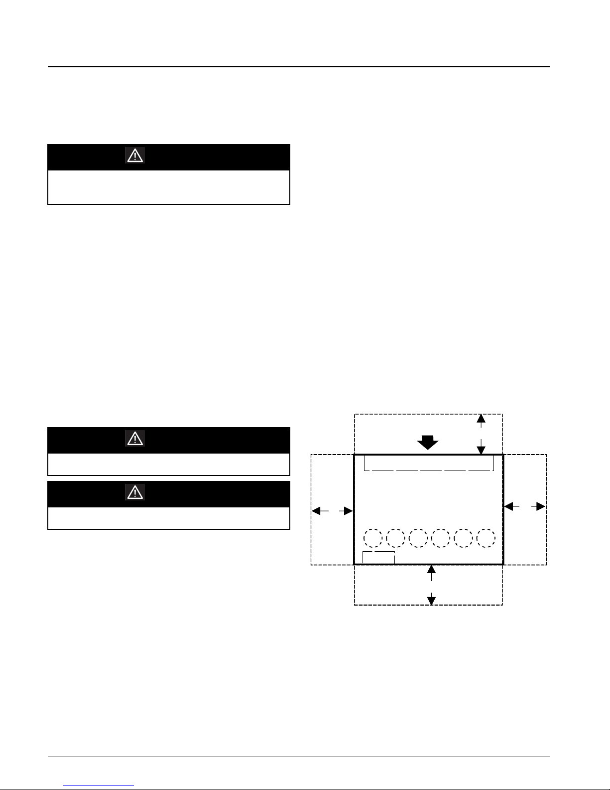
Unit front - 42"
Unit rear - 24"
Motor location side - 36"
Piping location side - 36"
Side without motor or piping -24"
Figure1. Recommended Service and Maintenance
Clearance
Airflow
24"
Do not attempt to install dollies in the center of the unit.
CAUTION
Units must not be moved in an upended position.
Floor surfaces must be protected when equipment is moved
across finished flooring. Plywood sheeting may be used to
protect surfaces and distribute weight loading.
Vibration Isolators
All units are provided with 1” neoprene isolation pads,
shipped separately. Pads are to be installed beneath the unit
and located at each corner and the center of each base channel. For units provided with more than six (6) isolator pads,
evenly space the additional pads under the front and rear
base channels.
Setting Factory Supplied Plenum
If the unit is provided with a factory plenum for field mounting, a forklift, slings or other suitable lifting means is
Evapora tor C oil
24"
or
36"
Compressors
1
35642
VFD
42"
36"
Removal of Shipping Restraints
Mechanical restraints are used to secure the spring mounted
fan during shipment. Restraints and shipping blocks must be
removed after unit has been set in its final location.
4 IM708
Page 5
Refrigerant Piping
Pressure Relief Valves
All units have individual condensers per refrigerant circuit
and each condenser is provided with a spring loaded relief
valve. The valve is set to open when refrigerant pressure
reaches 400 psig. The relief valve will accommodate a 1/2"
flare connection for applications where it is necessary to
connect vent piping and run it outside the building.
CAUTION
When refrigerant is vented to the outside of the building,
the vent piping should be installed as recommended in
ASHRAE Standard 15-1994.
IM708 5
Page 6

W ater Connections
General
Due to the variety of piping practices, it is advisable to follow the recommendations of local authorities. They can supply the installer with the proper building and safety codes
required for a safe and proper installation.
The piping should be installed with a minimum number of
bends and elevation changes for best performance. Piping
should contain:
1. Vibration eliminators to reduce vibration and noise
transmission to the building.
2. Shutoff valves to isolate the unit from the piping system
during unit servicing.
3. Manual or automatic air vent valves at the high points of
the system.
4. Some means of maintaining adequate system water
pressure (e.g., expansion tank or regulating valve).
5. Temperature and pressure indicators located at the unit
to aid in servicing.
6. A strainer or some means of removing foreign matter
from the water before it enters the pump. It should be
placed far enough upstream to prevent cavitation at the
pump inlet (consult pump manufacturer for recommendations). The use of a strainer will prolong pump life
and help maintain system performance.
7. Size piping to minimize system pressure drop.
mizer will typically elevate the water temperature by 5
to 10°F before entering the condenser, allowing suitable
condenser water temperatures whenever the tower supply temperature is 50°F or higher. Mechanical cooling is
locked out below 55°F EWT.
6. Head pressure control must be provided if entering condenser water temperatures will go below 55°F. Fan
cycling and/or modulating discharge dampers on the
cooling tower are often used, or a 3-way bypass around
the tower to maintain condenser water temperature.
Cooling tower control to maintain the temperature at
>55°F is generally more cost effective if multiple units
are in the loop. If valves are installed on the individual
SWP units, a single water regulating valve controlled by
circuit #1 head pressure should be used. The Lead/Lag
option needs to equal “NO”. When Lead/Lag equals
“NO” circuit #1 is always first on and last off. The
refrigerant pressure line from the valve should be connected to a gauge port on any liquid line service valve
located in the compressor #1 refrigerant circuit. Compressor #1 is located at the far left of the cabinet.
If the water regulating valve is placed in service with the
unit condensers, it should be installed in the water line leaving the condenser and should shut down to prevent water
from siphoning out of the condensers. For systems where a
constant pumping head is required, the water regulating
valve may be installed in a bypass line around the condensers. It must then open on falling discharge pressu re.
Condenser Piping
1. Units may be specified with water and condensate connections on either the left or right side of the unit.
2. All units have an individual condenser per refrigerant
circuit. All condensers are factory piped for a common
condenser water supply and a common condenser water
return connection.
3. Field piping connections are made to factory provided
piping located as indicated on the unit submittal drawings. The piping connections are run to the outside of
the unit cabinet. Connections are located behind a factory mounted shipping cover. All connections are copper sweat connections as indicated on unit dimensional
drawings.
4. Supply and return water connections must be made at
the proper locations as indicated by the dimensional
drawings. Supply (water in) connection is always the
lower connection.
5. Units with factory mounted water side economizer
should not require head pressure control. The econo-
These typical systems, depending on the specific application, must maintain a constant condensing pressure regardless of temperature conditions and must assure adequate
head pressure for proper thermal expansion valve operation.
A minimum head pressure of 180 psi (95°F condensing temperature) is recommended.
7. Condenser tube velocities must not exceed 10 feet per
second.
Figure2. Condenser Regulating Valve (refrigerant
pressure controlled
)
6 IM708
Page 7
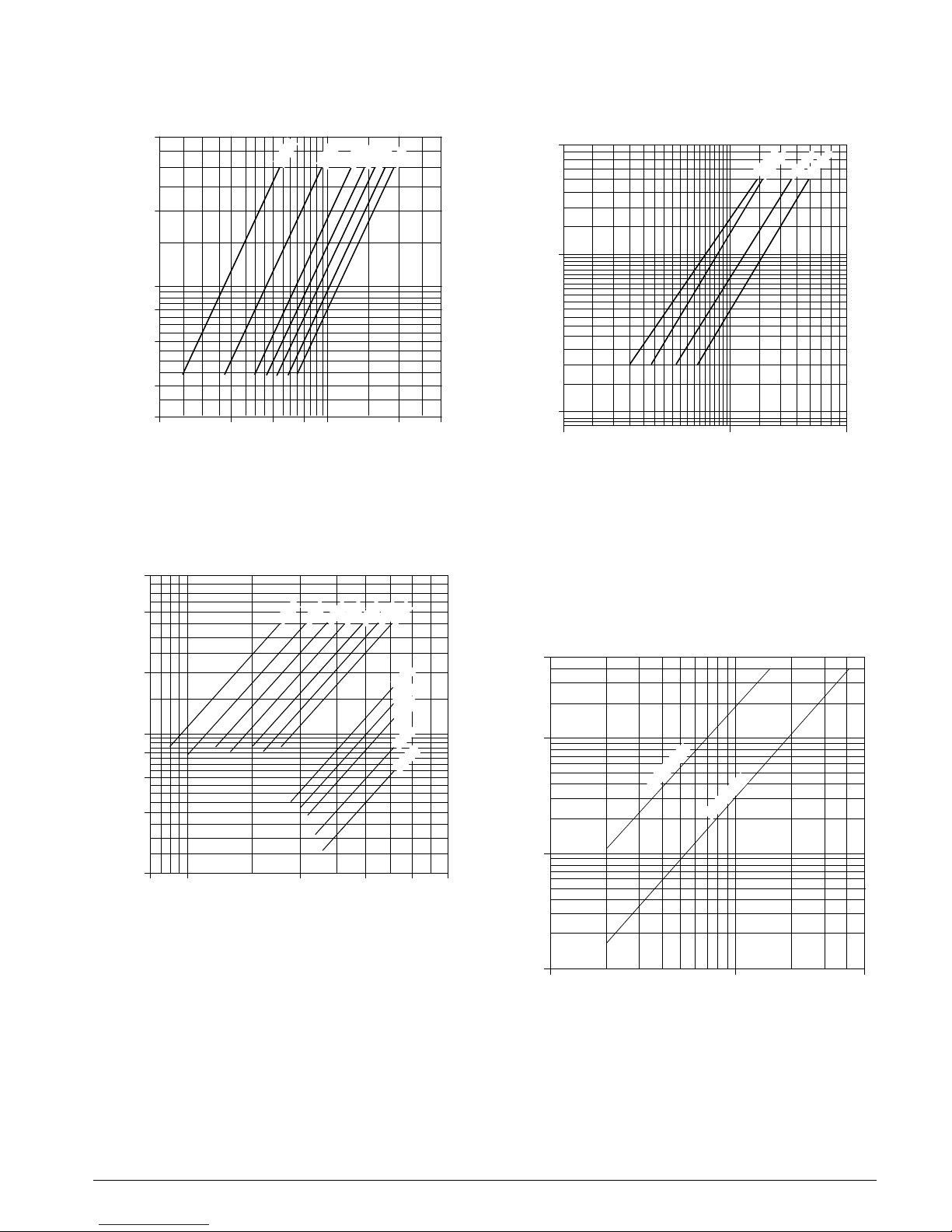
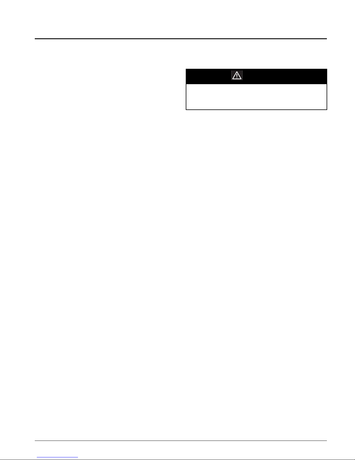
Figure3. Condenser water pressure drop SWP018 -
SWP040
40
24 HP
28 HP
12 HP
18 HP
32 HP
36 HP
40 HP
Figure5. Economizer water pressure drop, SPW018-
SPW105
50
035-040
045-095
105
018-028
20
O)
2
10
8
Pressure Drop (ft H
6
4
3
20
60 80
40
Condenser Flow Rate (gpm)
100
200 300
Note: HP = total unit compressor horsepower.
Figure4. Condenser water pressure drop SWP045 -
SWP105
60
O)
Pressure Drop (ft H
40
20
2
10
8
6
40HP
46HP
52HP
56HP
60HP
70HP
80HP
78HP
84HP
90HP
105HP
120HP
O)
2
10
Pressure Drop (ft H
1
Note:
10
Condenser Flow Rate (gpm)
!
Includes coil, control valves and interconnecting
100 500
piping.
"
Add this∆P to condenser ∆P to obtain unit ∆P
for pump selection.
Figure6. Water regulating valve pressure drop.
Head pressure control
40
10
O)
2
018-040
4
2
80 100
200 300
Condenser Flow Rate (gpm)
Note: HP = total unit compressor horsepower.
IM708 7
400 500
Pressure Drop (ft H
0.1
045-095
1
10
100
500
Condenser Flow Rate (gpm)
Page 8
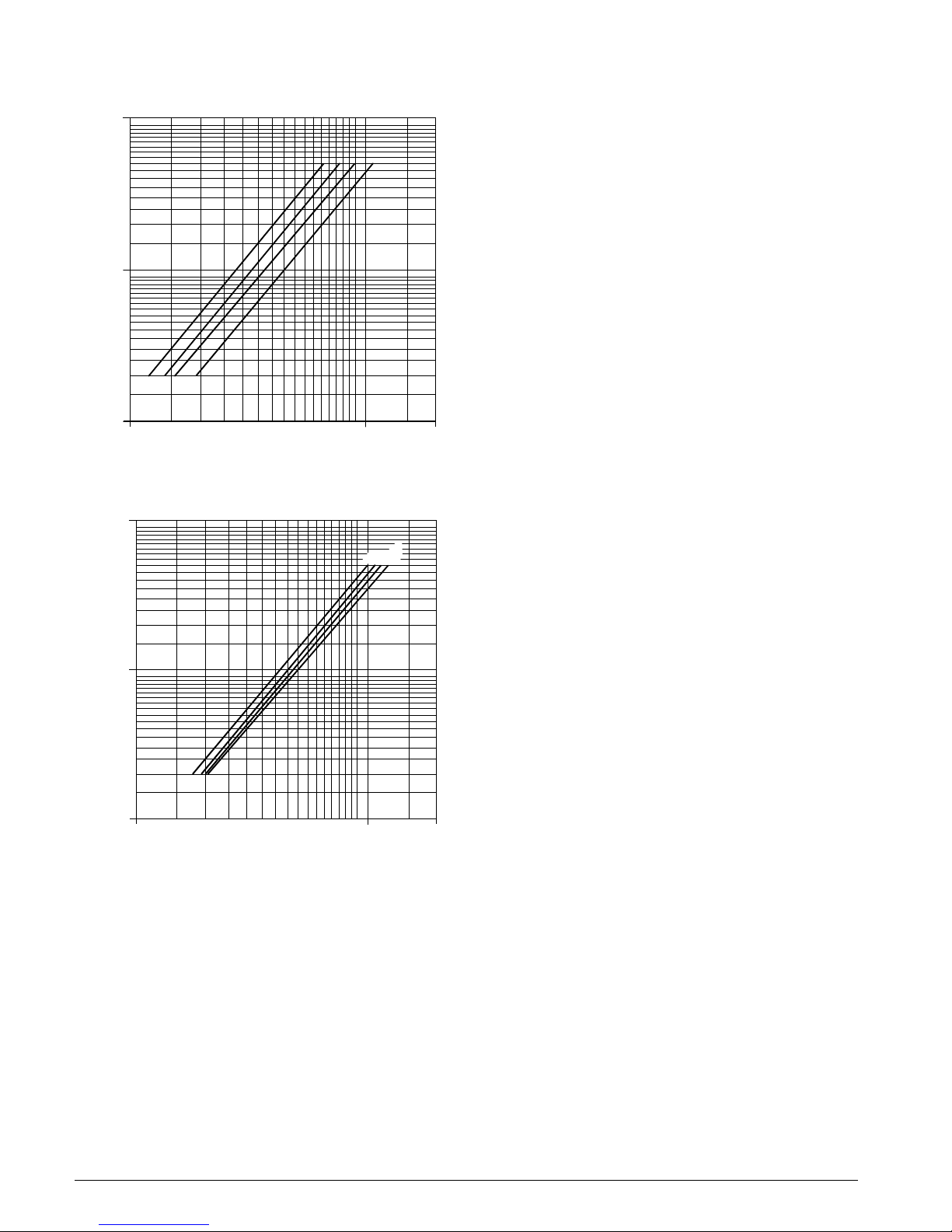
Figure7. Hot water coil pressure drop, SWP018 -
SWP040
100
018
035
023-028
040
O)
2
10
Pressure Drop (ft H
1
10
100
Water Flow Rate (gpm)
Hot water coil pressure drop, SWP045 - SWP105
100
Condensate Drain Connection
The condensate drain connection is 1 1/8" O.D.S. copper and
is located on the same end of the unit as the condenser water
connections. The drain is internally trapped at the factory
requiring no external trap. The condensate line should be
pitched away from the unit with a minimum slope of 1/8" per
foot.
Drain pans and the drain trap should be kept clean by periodic cleaning. A cleanout is provided as standard in the trap
to aid in cleaning.
200
O)
2
10
Pressur e Drop (ft H
1
10 100
Water Flow Rate (gpm)
055
045
065-095
105
200
8 IM708
Page 9
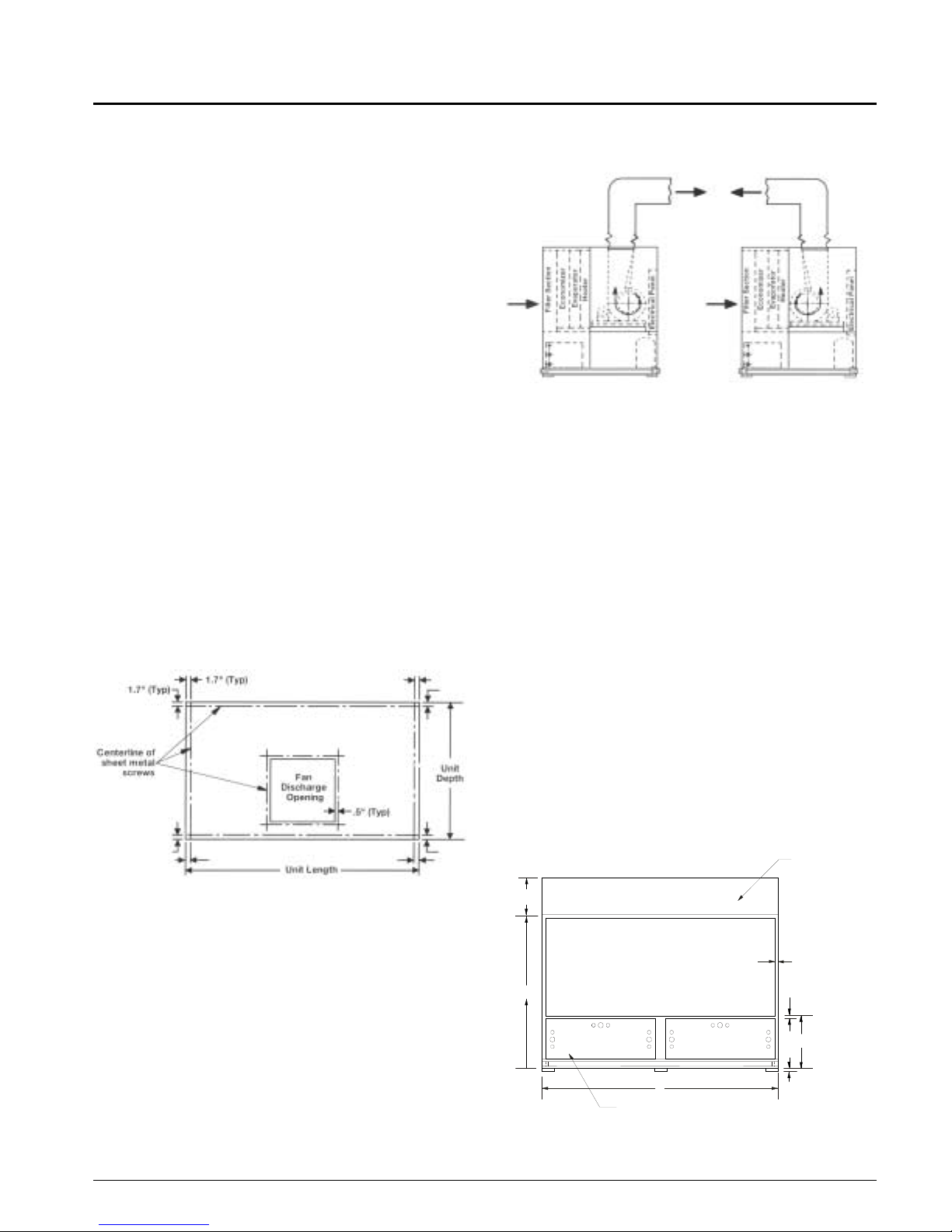
Duct Connections
Supply Air
For connection of supply ductwork directly to the unit, a
duct collar must first be mounted at the fan outlet, avoiding
the mounting screws located around the perimeter of the fan
discharge opening (see Figure 8). Fan discharge opening
sizes are indicated on the unit dimensional drawings. When
connecting ductwork to the unit, a canvas type connecting
collar is recommended.
Units are available in two fan configurations and should be
ducted as shown in Figure 9. Duct take-offs which go opposite to the direction of fan rotati on will result in an associated
system effect loss and reduced fan performance.
If a field fabricated plenum is used, duct take-off locations
should again be correctly oriented to the rotation of the fan to
minimize system losses. Refer to unit dimensional drawings
and Figure 8 for plenum mounting size requirements. Canvas type connectors are recommended at the duct connection
to the plenum.
Units are also available with a factory provided discharge
plenum. Supply duct connections to the plenum opening(s)
should include a canvas type connector. Plenum opening
sizes and locations will be indicated on the job submittal.
Figure8. Unit top detail
Figure9. Discharge duct configurations
Return Air
Return air to the unit can be arranged in two ways.
1. Ducted return
Return ductwork may be attached to the 2" flange around the
perimeter of the unit's return air opening (Refer to Figure
10). A canvas type duct connecting collar is recommended.
All ductwork connected to the unit should be of adequate
size and construction for the application. A canvas type connector is also recommended where the duct penetrates the
machine room wall(s). This will prevent vibration generated
by air movement in the duct from being transmitted out to
the occupied spaces.
Note: Do not obstruct unit access panel located below the
return opening.
2. Free return
The mechanical equipment room may be used as a return
plenum with no hard connection at the unit.
Note: Some building codes do not allow the use of the
mechanical room as a return plenum. Applicable
local codes should be checked for each installation.
Figure10.Back Elevation
(Optional)
Multi-Directional
Plenum
29”
K x L
Return Air Opening
D
B
Mechanical
Access
(See Notes)
(See Notes)
2.0” Typical
2.0”
M
1” Neoprene
Isolation Pads,
Shipped Separately
B25
IM708 9
Page 10
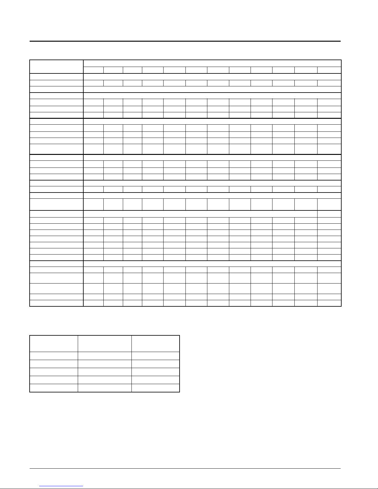
Physical Data
Table 2: SWP 018 Through SWP 105
Data
Compressor
Quantity 2, 3, 4 3, 4 4 4 4 4 4 4 4 4 4, 6 6
Size See Unit Data Plate
Evaporator Coil
Face Area (Ft.2)
Rows 4, 6 4, 6 4, 6 4, 6 4, 6 4, 6 6 6 6 6 6 6
Fpi 12 12 12 12 12 12 12 12 12 12 12 12
Waterside Economizer Coil
Face Area (Ft.2)
Rows 4444 4 4 4 4 4 4 4 4
Fpi 12 12 12 12 12 12 12 12 12 12 12 12
Maximum Working Pressure
(psig)
Hot Water Heating Coil
Face Area (Ft.2)
Rows 1, 2 1, 2 1, 2 1, 2 1, 2 1, 2 1, 2 1, 2 1, 2 1 1 1
Fpi 12 12 12 12 12 12 12 12 12 12 12 12
Electric Heat
Kw 34 34 34 34 34 68 68 68 68 68 68 68
Filters
(Quantity) Size 4” Depth
Evaporator Fan
Quantity 1111 1 1 1 1 1 1 1 1
Size 15 18 18 20 20 22 25 25 25 27 27 33
Minimum Horsepower 5 7.5 10 10 15 15 20 20 20 25 30 40
Maximum Horsepower 10 15 20 20 25 30 40 40 40 50 60 60
Minimum Design cfm, CV 2950 3825 4425 5825 6925 7675 9025 10375 11575 12775 13975 15800
Minimum Design cfm, VAV 4720 6120 7080 9320 11080 12280 14440 16600 18520 20440 22360 25280
Maximum Design cfm 7080 9180 10620 13980 16620 18420 21660 24900 27780 30660 33540 37920
Condenser
Quantity 2, 3, 4 3, 4 4 4 4 4 4 4 4 4 4, 6 6
Waterside Working Pressure
(psig)
Minimum Entering
Temperature (F)
Minimum GPM 25 41 53 66 69 94 105 105 121 134 138 180
Maximum GPM 88 108 125 159 166 215 237 237 251 349 358 493
a
a. Standard fan TSP limit is 5.5 inch of water. Consult your local McQuay sales representative for applications beyond this range.
018 023 028 035 040 045 055 065 070 080 095 105
11.8 15.3 17.7 23.3 27.7 30.7 36.1 41.5 46.3 51.1 55.9 63.2
11.8 15.3 17.7 23.3 27.7 30.7 36.1 41.5 46.3 51.1 55.9 63.2
400 400 400 400 400 400 400 400 400 400 400 400
9.3 12.8 15.2 20.2 24.5 26.8 30.4 35.8 39.9 44.4 48.3 51.9
(6)20x20x4
(2)25x20x4
(6)20x20x4
(2)25x20x4
400 400 400 400 400 400 400 400 400 400 400 400
55° 55° 55° 55° 55° 55° 55° 55 55° 55° 55° 55°
(6)20x20x4
(2)25x20x4
(10)25x20x4 (10)25x20x4 (12)25x20x4 (12)25x20x4 (18) 20x20x4 (6)16x20x4
SWP Model Size
(12)25x20x4
(3)20x20x4
(15)25x20x4
(6)16x20x4
(15)25x20x4
(4)16x20x4
(17)20x25x4
(1)16x25x4
Table 3: Compressor circuit charge
COMPRESSOR
(HP)
69 lbs.66
10 14 lbs. 112
13 18 lbs. 128
15 22 lbs. 256
20 27 lbs. 256
*Charge quantities listed are average. Actual cha rg e qu an tity is dependent on
individual unit evaporator coil circu iting. Actual char ge quantities are st amped
on each unit nameplate.
10 IM708
*REFRIGERANT
CHARGE PER
CIRCUIT (R-22)
OIL CHARGE
PER CIRCUIT
(OZ.)
Page 11
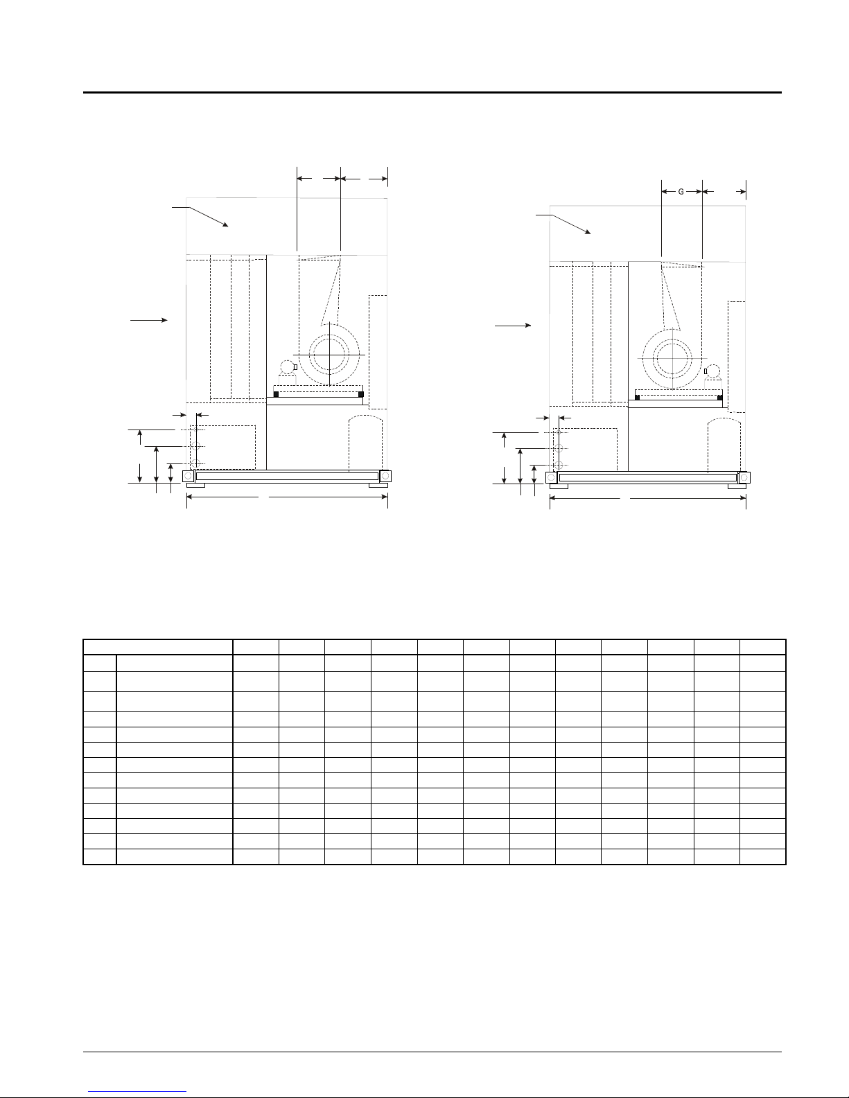
Dimensional Data
Figure 1 1. Left Side Front (CW) Disch arge with 0ptional
Multi-Directional Plenum
(Optional)
Multi-Directional
Plenum
(See Notes)
K x L Return Air
3.25”
19.0"
14.75”
8.75”
Filter Section
Outlet
Inlet
G
Heater
Evaporator
Economizer
A
J
Electrical Panel
A21
Figure 12. Left Side Back (CCW) Discharge with
0ptional Multi-Directional Plenum
9.63"
(18-95)
10.31
(Optional)
Multi-Directional
Plenum
(See Notes)
K x L Return Air
3.25”
19.0"
14.75”
Heater
Evaporator
Economizer
Filter Section
Outlet
Inlet
A
8.75”
(105)
Electrical Panel
A22
Note: Select unit arrangement on the unit selection.
Plenum can be shipped separately. Please indicate on the unit submittal. Indicate size and location of plenum openings on the unit submittal. All openings are on plenum centerline. For additional information refer to plenum certified drawing .
Table 4:
BASIC UNIT 018 023 028 035 040 045 055 065 070 080 095 105
A
B
D
FFan Disch. 18.62 21.88 21.88 24.75 24.75 27.25 31.25 31.25 31.25 34.25 34.25 47.25
G Fan Disch. ^ Opening 15.88 18.88 18.88 24.75 24.75 27.25 31.25 31.25 31.25 34.25 34.25 34.94
H Fan Disch. Location 32.69 31.06 31.06 37.62 37.62 46.38 44.38 44.38 50.38 54.88 60.88 54.40
J Fan Disch. Location 22.50 18.81 18.81 20.12 20.12 21.06 21.32 21.32 21.32 23.82 23.82 33.46
K Return Opening Height 41.44 41.44 41.44 51.44 51.44 51.44 51.44 62.20 62.20 62.20 62.20 70.20
L Return Opening Length 80.00 80.00 80.00 96.00 96.00 116.00 116.00 116.00 128.00 140.00 152.00 152.00
M Base of Return Opening 28.62 28.62 28.62 28.62 28.62 28.62 28.62 23.87 23.87 23.87 23.87 23.87
N Water Out/In (ODS) 2-1/8 2-1/8 2-1/8 2-5/8 2-5/8 2-5/8 3-1/8 3-1/8 3-1/8 3-1/8 3-1/8 3-1/8
P 1 Row HW Donn (ODS) 1-5/8 1-5/8 1-5/8 1-5/8 1-5/8 1-5/8 1-5/8 1-5/8 2-1/8 2-1/8 2-1/8 2-1/8
P 2 Row HW Conn (ODS) 1-5/8 1-5/8 1-5/8 1-5/8 1-5/8 2-1/8 2-1/8 2-1/8 2-1/8 - - -
b
Deptha
b
Lengtha
b
Heighta
a. Dimensions do not include handle, latch or fastener extensions.
b. For shipping dimensions add 4" (102mm) to depth, 8" (204mm) to length, and 4" (102mm) to height.
72.00 72.00 72.00 72.00 72.00 81.00 81.00 81.00 81.00 84.00 84.00 96.00
84.00 84.00 84.00 100.00 100.00 120.00 120.00 120.00 132.00 144.00 156.00 156.00
82.00 82.00 82.00 82.00 82.00 82.00 82.00 88.00 88.00 88.00 88.00 96.00
IM708 11
Page 12
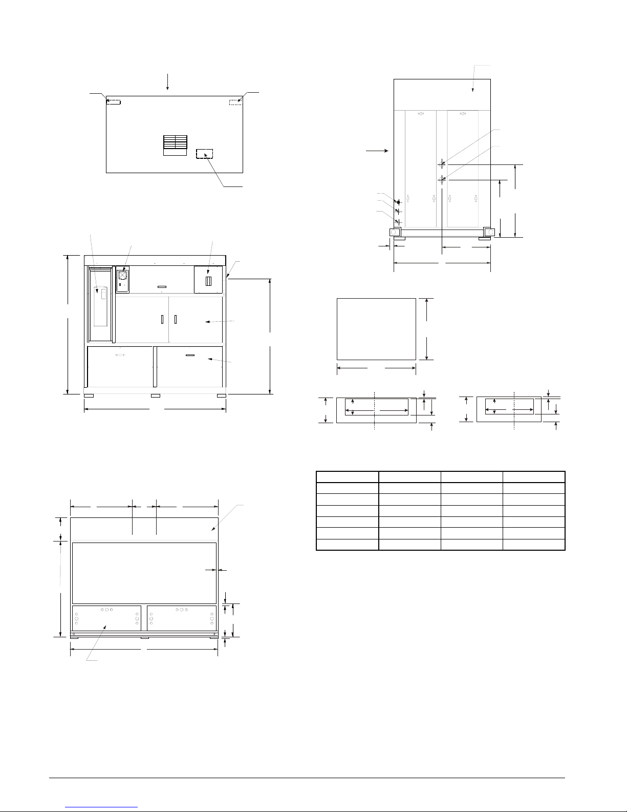
Figure 13. Unit Front Plan
Return Air
Left Side
Piping Connections
(See Notes)
Figure 14. Front Elevation
ASD (Optio nal)
MicroT ech II Panel
D
Supply
Fan Motor
Disconnect
Switch (Optional)
Power Entry
7/8" Pilot K.O.
Electrical
Access
(Optional)
Right Side
Piping Connections
(See Notes)
A23
72"
Figure 16. Left Side
K x L Return Air
1-1/8” ODS Drain
(N) W a te r O ut
(N) W ater In
Lifting Lug
1” Typ.
A/2
A
Figure 17. Discharge Plenum (Optional)
Plan View
Depth
Multi-Directional
(Optional)
Plenum
(See Notes, Page 11)
(P) Ho t W a te r O u t
(P) Ho t W a te r In
44.5”
38.5”
Mechanical
Access
B
Note: Service connections determined when facing the front of the
unit. Left-hand standard, right-hand optional. Please indicate on
the unit submittal.
Note: Unit sizes 018, 023 and 028 have a single mechanical access
panel in bottom front and bottom back.
Figure 15. Back Elevation
H H
29”
D
Mechanical
(See Notes)
F
K x L
Return Air O pening
B
Access
Multi-Directional
Plenum
(See Notes, Page 11)
2.0” Typical
2.0”
M
1” Neoprene
Isolation Pads,
Shipped Separately
(Optional)
Length
29”
Front/Back Elevation
H
A
3”
2” Min
29”
Left/Right Elevation
H
B
Table 5. Discharge Plenum
Unit Size Length (in.) Depth (in.) Height (in.)
018D-028D 84 72 29
035D-040D 100 72 29
045D-065D 120 81 29
070D 132 81 29
080D 144 84 29
095D-105D 156 84 29
3”
A27
2” Min
12 IM708
Page 13
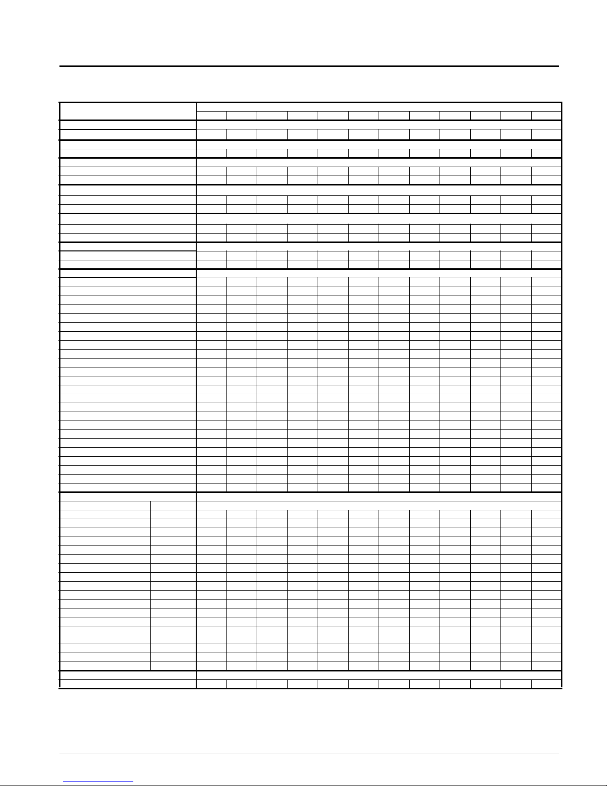
Unit Weights
Table 6. Unit and Component Weight in lbs.
Unit Weights
Basic Configuration
SWP basic unit
Filters
4" 30% or 65% efficiency 38 38 38 55 55 66 66 79 87 96 104 112
Evaporator Coil
6 Row, 12 fpi 250 294 321 417 468 506 577 642 693 755 819 926
4 Row, 12 fpi 206238257333368395------
Water Economizer Coil
4 Row, 12 fpi 306 338 357 458 493 520 598 648 678 723 820 927
Water weight 51 66 75 94 111 119 150 168 187 203 218 281
Hot Water Coil
1 Row, 12 fpi 71 97 114 130 158 160 170 200 328 337 345 371
Water weight 16 20 23 28 32 37 41 49 55 59 62 62
Electric Heat
34 KW 2020202020------68 KW -----40404040404040
Supply Fan Motors
3 HP ODP 71------ ---5 HP ODP 82------ ----
7.5 HP ODP 124124----- -- -10 HP ODP 144 144 144 144 - - - - - - 15 HP ODP - 185 185 185 185 185 - - - - 20 HP ODP - - 214 214 214 214 214 214 214 - - 25 HP ODP - - - - 266 266 266 266 266 266 - 30 HP ODP - - - - - 310 310 310 310 310 310 40 HP ODP ------404404404404404404
50 HP ODP ------- -452452452
60 HP ODP ------- --620620
75 HP ODP ------- ---836
3 HP TEFC 72------ ---5 HP TEFC 85------ ----
7.5 HP TEFC 140140----- ---10 HP TEFC 170 170 170 170 - - - - - - 15 HP TEFC - 235 235 235 235 235 - - - - 20 HP TEFC - - 300 300 300 300 300 300 300 - - 25 HP TEFC - - - - 330 330 330 330 330 330 - 30 HP TEFC - - - - - 390 390 390 390 390 390 40 HP TEFC ------510510510510510510
50 HP TEFC ------- -570570570
60 HP TEFC ------- --850850
75 HP TEFC ------- ---900
Compressor/Condens e r As sembly
(2)6HP 26 368------ ---(3)6HP 35 538538----- ---(4)6HP 43 699 699 699 699 - - - - - - (3)6HP, (1)10HP 57 - 843 843 843 843 - - - - - (2)6HP, (2)10HP 66 - - 974 974 974 - - - - - (1)6HP, (3)10HP 74 - - - 1115 1115 - - - - - (4)10HP 95 - - - 1263 1263 1263 1263 1263 - - - (2)10HP, (2)13HP 106 - - - - - 1404 1404 1404 - - - (4)13HP 118 - - - - - 1549 1549 1549 1549 - - (2)13HP, (2)15HP 129 - - - - - 1709 1709 1709 1709 1709 1709 (4)15HP 141 - - - - - 1867 1867 1867 1867 1867 1867 (2)15HP, (2)20HP 152 -------198219821982 1982 (4)20HP 190 ------- -2096 2096 (6)13HP 167 ------- --22652265
(3)13HP, (3)15HP 178 ------- --24792479
(6)15HP 188 ------- --26932693
(3)15HP, (3)20HP 209 ------- --29142914
(6)20HP 229 ------- --31353135
Discharge Plenum
Factory Installed, 29” 636 636 636 711 711 862 862 862 922 1003 1064 1064
a. Base Weight includes supply fan without motor.
b. Water economizer weight includes valves and piping.
c. The values in this table do not include water weight.
d. Hot water coil weight includes valve and piping.
a
b c
d
c
Water Weight
018 023 028 035 040 045 055 065 070 080 095 105
2226 2313 2318 2638 2643 3110 3279 3406 3734 4021 4246 4673
Unit Size
IM708 13
Page 14
Field Wiring
General
Wiring must comply with all applicable codes and ordinances. Warranty is voided if wiring is not in accordance
with specifications. An open fuse indicates a short, ground or
overload. Before replacing a fuse or restarting a compressor
or fan motor, the trouble must be found and corrected. Copper wire is recommended for all power lead terminations.
Contact factory for information concerning aluminum wire
power lead terminations.
A single power terminal block is provided as standard and
wiring within the unit is done in accordance with the
National Electric Code. All branch circuits within the control
panel are individually fused. A single field supplied disconnect is required or a unit mounted nonfused disconnect can
be ordered with the unit.
A 7/8” knockout is located on the right-hand unit upright for
locating unit power entry. 24V field connections are suitable
for Class II wiring.
Unit Disconnect
Disconnecting means are addressed by Article 440 of the
National Electric Code (NEC) which requires 'disconnecting
means capable of disconnecting air conditioning and refrigerant equipment including motor-compressors, and controllers, from the circuit feeder." The disconnect switch should
be selected and located within the NEC guidelines. Location
requirements per NEC are that the disconnect be located in a
readily accessible position within sight (50 feet) of the unit.
A factory mounted nonfused disconnect is available.
Table 7. Compressor Motors
Compressor
HP
6
10
13
15
20
208/60/3 230/60/3 400/50/3 460/60/3 575/60/3
RLA LRA RLA LRA RLA LRA RLA LRA RLA LRA
17.9 156.0 16.2 156.0 8.1 70.0 8.1 70.0 6.5 54.0
31.2 239.0 28.2 239.0 14.1 125.0 14.1 125.0 11.3 80.0
35.6 350.0 32.0 350.0 16.0 158.0 16.0 158.0 12.8 125.0
42.1 425.0 38.0 425.0 19.0 187.0 19.0 187.0 15.2 148.0
74.0 360.0 67.2 360.0 33.6 180.0 33.6 180.0 36.9 144.0
Return Air and Outside Air Sensors
All units are provided with a return air sensor. The outside
air sensor is optional and can be ordered with the unit. The
return air sensor is connected to the input control board and
is coiled up and placed in the control box of the unit for shipment. The return air sensor must be field installed in the
return air stream for proper unit operation. The outside air
sensor is shipped loose in a package and is located on the
floor of the fan section. The mixed air temperature sensor is
already installed at the inlet of the unit.
The sensors must be mounted in areas that are exposed to
representative temperature conditions. The sensor should be
mounted at a position that has good air mixing and does not
have stratification. The sensor can be mounted in the ductwork using a grommet, see Figure 18.
Figure 18. Return/Outside Air Sensor Mounting
Sensor
Ductwork
The return air sensor is connected to the unit’s input board at
location AI4, see IM710. The outside air sensor is field
wired to terminal strip TB2. The sensor is to be connected at
terminals 124 and 125.
Grommet
Table 8. Electric Heaters
SWP UNIT SIZE
018 - 040
045 - 105
14 IM708
208V/60HZ/3PH 230V/60HZ/3PH 400V/50HZ/3PH 460V/60HZ/3PH 575V/60HZ/3PH
kW MBH FLA kW MBH FLA kW MBH FLA kW MBH FLA kW MBH FLA
27.8 94 77.2 34 116 85.6 25.7 88 37.2 34 116 42.8 34 116 34.2
55.6 190 154.4 68 232 170.9 51.4 175 74.4 68 232 85.6 68 232 68.4
Page 15

Table 9. SAF Motor Nameplate Amp Table
Horsepower TYPE
3
5
7.5
10
15
20
25
30
40
50
60
75
a. 460/60/3 motors are used. Derate nameplate horsepower to 0.83 to obtain actual horsepower.
High Efficiency 9.9 9.0 4.5 4.5 3.4
Premium Efficiency 9.3 8.2 4.1 4.1 3.1
High Efficiency 14.8 14.0 7.0 7.0 5.3
Premium Efficiency 15.7 13.6 6.8 6.8 5.2
High Efficiency 22.3 21.6 10.8 10.8 8.2
Premium Efficiency 22.3 20.0 10.0 10.0 7.4
High Efficiency 29.7 28.0 14.0 14.0 11.0
Premium Efficiency 29.0 25.8 12.9 12.9 10.3
High Efficiency 44.4 40.6 20.3 20.3 16.2
Premium Efficiency 43.4 37.8 18.9 18.9 14.1
High Efficiency 57.0 50.0 25.0 25.0 20.0
Premium Efficiency 57.0 49.0 24.5 24.5 18.9
High Efficiency 69.8 62.0 31.0 31.0 24.3
Premium Efficiency 70.5 61.0 30.5 30.5 24.2
High Efficiency 86.5 75.0 37.5 37.5 30.0
Premium Efficiency 83.3 72.4 36.2 36.2 29.8
High Efficiency 117.0 102.0 51.0 51.0 40.0
Premium Efficiency 110.0 96.0 48.0 48.0 38.0
High Efficiency 138.0 124.0 62.0 62.0 49.2
Premium Efficiency 137.0 120.0 60.0 60.0 47.5
High Efficiency 154.0 144.0 72.0 72.0 57.4
Premium Efficiency 159.0 140.0 70.0 70.0 56.0
High Efficiency 189.0 176.0 88.0 88.0 71.0
Premium Efficiency 195.0 170.0 85.0 85.0 65.5
208/60/3 230/60/3
FLA FLA FLA FLA FLA
400/50/3
a
460/60/3 575/60/3
IM708 15
Page 16

Supply Power Wiring
1. Units require three-phase power supply.
2. Allowable voltage tolerances:
a. 60 Hertz
Nameplate 208V: Min.187V, Max. 229V
Nameplate 230V: Min.207V, Max. 253V
Nameplate 460V: Min.414V, Max. 506V
Nameplate 575V: Min.518V, Max. 632V
b. 50 Hertz
Nameplate 400V: Min. 342V, Max. 418V
3. Power lead wire sizing:
a. For units with cooling capability (all concurrent loads)
with or without hot water heating and circuits with
motor loads only:
MCA = 1.25 (largest motor RLA or FLA) + other loads
+ 2 amps.
b. For units with cooling capability and nonconcurrent
electric heat capability:
Lug Sizes For Single Disconnect or
Power Block
Table 10. Single Disconnect
UNIT VOLTAGE SIZE (AMPS)
018-028
018-028
018-028
035-040
035-040
035
040
045
045
045
055-070
055-070
055-070
080-095
080-095
080-095
095-105 (6 Comp)
095-105 (6 Comp)
095-105 (6 Comp)
a. Disconnect is 250 amps with electric heat.
Table 11. Lug Sizes For Single Disconnect
208/230 225
400/460 100
575 100
208/230 225
400/460 150
575 100
575 150
208/230 400
400/460
575 150
208/230 400
400/460 250
575 150
208/230 600
400/460 250
575 250
208/230 N/A
400/460 250
575 250
150
a
In the cooling mode, the loads will be composed of supply fan motor and compressors. In heating mode, the
loads will be composed of supply fan motor and electric
heater. The MCA is calculated for unit running in either
mode; the highest value obtained is used for the MCA.
(1)For unit in cooling mode:
MCA = 1.25 (largest RLA or FLA) + other loads + 2
amps.
(2)For unit in heating mode:
MCA = 1.25 (electric heat FLA + Fan FLA) + 2 amps.
4. Size wires in accordance with T able 310-16 or 310-19 of
the National Electrical Code.
5. Wires should be sized for a maximum of 3% voltage
drop.
DISCONNECT SIZE LUG SIZE
100
150
225
250
400
600
#6-2/0
#2-3/0
#3-300 MCM
#4-350 MCM
250 MCM-500 MCM
250 MCM-350 MCM
Table 12. Lug Sizes For Power Block
UNIT VOLTAGE LUG SIZE
018-045
055-105
055-105
Note: Use copper wire only.
ALL #6-400 MCM
400/460/575 #6-400 MCM
208/230 1/0-600 MCM
16 IM708
Page 17

Control Center
All electrical controls are enclosed in a central control center
located at the front of the unit. The control center is divided
into two separate compartments, high and low voltage. The
lower compartment houses the high voltage components and
can be accessed through the “Electrical Access" panels indicated on the dimensional drawing. Behind these access panels are hinged dead front panels for further operator safety.
High voltage components include:
1. Fan Motor Contactor, M30
2. Fan Motor Overload, OL10
3. Fan Motor Fuse, FB10
4. Compressor Contactors, M1-M6
5. Compressor Fuses, FB1-FB6
6. Electric Heat Contactors, M11-M16
7. Transformer, T1, T2, T3
8. Disconnect Switch, DS1-DS2
9. Power Block, PB1-PB2
Figure 19. Typical Control Center Layout
High and Low Voltage Compartments
LonMark Communication Card
BACNet Communication Card
If the optional disconnect switch is provided, the switch handle is visible and accessible without removing any safety or
access panels.
Low voltage components are located in the upper left compartment, and include:
1. MicroTech II Main Control Board, MCB
2. Duct Static Pressure Sensor, SPS1
3. Optional 2nd Duct Static Pressure Sensor, SPS2
4. Optional BACNet Ethernet Communication Card,
5. Optional BACNet MSTP Communication Card,
6. Optional LonMark Communicati on Card,
7. Compressor Control Board, CCB #1
8. Compressor Control Board, CCB #2
(6 compressor units only)
Located on the face of the unit is the interactive MicroTech
II keypad/display, unit switch, system indicator light and
power indicator.
Note: IM710 has additional layout of the control center.
Phase Voltage
Monitor
Power Block
Disconnect Switch
(Optional)
Adjustable Frequency
Drive (Optional)
IM708 17
Transformer, Control Output, 24V, T3
Transformer, Control Output, 24V, T2
Duct Static Pressure Sensor
Transformer, Main Control, 115V, T1
Page 18

Electrical Legend
Designation Description Standard Location Designation Description Standard Location
ACT1 ACTUATOR,VARIABLE INLET VANES SUPPLY FAN SEC-
ACT2 ACTUAT OR,BYPASS VALVE CONDENSER VALVE OAT OUTSIDE AIR TEMP. SENSOR EXTERNAL
ACT3 ACTUATOR,WATERSIDE ECONOMIZER WATERSIDE ECONO
AFD10 ADJUST.FREQUENCY DRIVE--SUPPLY FAN MAIN CONTROL PB1 POWE R BL OCK--TOTAL UNIT OR
CCB1,2 COMPR CONTROL BOARDS--REFRIG. CIR-
CUITS
COMPR#1-6 COMPRESSORS #1--6 COMPRESSOR SEC-
DAT DISCHARGE AIR TEMP. SENSOR NEAR FAN INLET PC7 PRESSURE CONTROL--PROOF AIRFLOW FAN SECTION
DHL DUCT HI-LIMIT FAN SECTION PM1 PHONE MODEM MAIN CONTROL
DS1 DISCONNECT--TOTAL UNIT OR COND/HEAT MAIN CONTROL PSR1,2 PRESSURE SENSOR,REFRIGERANT LIQ. SHUTOFF
DS2 DISCONNECT--SAF/RAF/CONTROLS MAIN CONTROL PVM1 PHASE VOLTAGE MONITOR MAIN CONTROL
EWT ENT. COND. WATER SENSOR COND. WATER INLET PVM2 PHASE VOLTAGE MONITOR MAIN CONTROL
F1 FUS E--CONTROL CIRCUIT MAIN CONTROL R11 RELAY--ELECTRIC HEAT STAGE 1 HW/S
FB10 FUSEBLOCK--SUPPLY FAN MAIN CONTROL R12 RELAY--ELECTRIC HEAT STAGE 2 HW/S
FB11,12 FUSEBLOCKS--ELECTRIC HEAT MAIN CONTROL R1-6 RELAYS--HI-PRESSURE MAIN CONTROL
FB1--6 FUSEBLOCKS--COMPRESSOR #1-6 MAIN CONTROL R18 RELAY--COOL ENABLE MAIN CONTROL
FB8 FUSEBLOCK--MAIN TRANSFORMER MAIN CONTROL R67 RELAY--ENABLE SUPPLY FAN MAIN CONTROL
FP1-6 FROST PROTECTION--REFRIG. CIRCUITS EVAP. COIL RAE RETURN AIR ENTHALPY EXTERNAL
FS1 FREEZESTAT CONTROL BT/DT COIL RAT RETURN AIR TEMP. SENSOR EXTERNAL
GRD GROUND ALL CONTROL BOX S1 SWITCH--SYSTEM ON/OFF MAIN CONTROL
HL13-14 HI-LIMITS, PWR, ELEC HEATERS ELECTRIC HEAT
HP1-6 HI-PRESSURE CONTROLS, REFRIG ON COMPRESSORS
HTR-11,12 ELECTRIC HEATERS DX COIL S8 SWITCH--COOL ENABLE MAIN CONTROL
HTR-15,16 ELECTRIC HEATERS DX COIL S9 SWITCH--HEAT MAIN CONTROL
HTR1-6 CRANKCASE HEATERS ON COMPRESSORS
HUM1 HUMIDSTAT SENSOR EXTERNAL SD2 SMOKE DETECTOR--RETURN FAN EXTERNAL
LP1-6 LO-PRESSURE CONTROLS, REFRIG ON COMPRESSORS
LWT LEAVING COND. WATER SENSOR COND. WATER OUT-
M10 CONTACTOR--SUPPLY FAN MAIN CONTROL T2 TRANSFORMER--CONTROL INPUT 24V MAIN CONTROL
M11,12 CONTACTORS--ELECTRIC HEAT CONTROL M AIN CONTROL T3 TRANSFORMER--CONTROL OUTPUT 24V MAIN CONTROL
M13,14 CONTACTORS--ELECTRIC HEAT SAFETY MAIN CONTROL TB10 TERMINAL BLOCK-- MAIN CONTROL
M15,16 CONTACTORS--ELECTRIC HEAT CONTROL MAIN CONTROL TB2 TERMINAL BLOCK--24V-FACTORY/FIELD MAIN CONTROL
M1-6 CONTACTORS--COMPR#1-6 MAIN CONTROL TB3 TERMINAL BLOCK--24V- MAIN CONTROL
M17,18 CONTACTORS--ELECTRIC HEAT SAFETY MAIN CONTROL TB4 TERMINAL BLOCK--24V-COMPRESSOR MAIN CONTROL
M30 CONTACTOR--INVERTER BYPASS MAIN CONTROL TB5 TERMINAL BLOCK--115V-FACTORY/FIELD MAIN CONTROL
MAT MIXED AIR TEMP SENSOR BEHIND FILTERS TB6 TERMINAL BLOCK--115V/24V FACTORY MAIN CONTROL
MCB1 MICROPROCESSOR CIRCUIT BOARD #1 MAIN CONTROL TB8 TERMINAL BLOCK-- MAIN CONTROL
MJ MECHANICAL JUMPERS ON TEMINAL
MP1-6 MOTOR PROTECTOR--COMPR#1-6 ON COMPRESSORS
NB1 NEUTRAL BLOCKS MAIN CONTROL WF1 CONDENSER WATER FLOW SWITCH NEAR CONDENSER
TION
VALVE
MAIN CONTROL PB2 POWER BLOCK--SAF/RAF/CONTROLS MAIN CONTROL
TION
JCT.BOX
#1-6
#1-6
#1-6
LET
BLOCKS
#1-6
OAE OUTSIDE AIR ENTHALPY EXTERNAL
OL10 OVERLOAD RELAY--SUPPLY FAN MAIN CONTROL
COMPR/HEAT
PC5 PRESSURE CONTROL--CLOGGED FILTER FAN SECTION
CLOSE
OPEN
S4,5 SWITCHES--INVERTER BYPASS MAIN CONTROL
S7 SWITCH--LOCAL ON/OFF TO CONTROLLER MAIN CONTROL
SD1 SMOKE DETECTOR--SUPPLY FAN EXTERNAL
SPS1,2 STATIC PRESSURE SENSORS--DUCT/BLDG MAIN CONTROL
T1 TRANSFORMER--MAIN CONTROL
(LINE/115V)
VM1 VALVE MOTOR #1--HEATING NEAR HOT WA T ER
VM5 VALVE MOTOR #5--COOLING NEAR CHILLED
ZNT1 ZONE TEMP. SENSOR--SETBACK FIELD INSTALLED
MAIN CONTROL
VALVES
MAIN CONTROL
MAIN CONTROL
MAIN CONTROL
INLET
WATER
1.
2.
3.
4.
5.
6.
7.
8.
9.
18 IM708
200
M/J
FIELD WIRING
TERMINA L
FIELD WIRING TERMINAL
TERMINAL P.C. BOARD FACTORY WIRED
WIRE NUMBER
WIRE CONNECTOR
OPTION BLOCK
PLUG IN CONNECTOR
MECHANICAL JUMPER
Page 19

Typical Wiring Schematics
Figure 20. Power Schematic
IM708 19
Page 20

Figure 21. Input Schematic, Discharge Air Control (DAC)
20 IM708
Page 21

Figure 22. Input Schematic, Zone or Space Comfort Control (SCC)
IM708 21
Page 22

Figure 23. Output Schematic, Actuator Control
22 IM708
Page 23

Figure 24. Output Schematic, Auxiliary Fan Start/Stop Control
IM708 23
Page 24

Figure 25. Output Schematic, Actuator Control
24 IM708
Page 25

Figure 26. Output Schematic, Compressor Control (4 Compressors/4, 5 or 6 Stage)
IM708 25
Page 26

Figure 27. Output Schematic, Compressor Control (6 Compressors / 6 Stage)
26 IM708
Page 27

Standard Controls
High Pressure Switches
The high pressure switch (HP1-HP6) is a single pole pressure activated device that opens on a pressure rise. When the
switch opens it de-energizes the compressor circuit, shutting
down the compressor. The MicroTech II controller will display an alarm condition. Once the cause of the fault has been
identified and corrected, the unit may be manually reset
through the MicroTech II keypad/display interface. The control is attached to a Shrader fitting and is located at the compressor. To check the control, shut off water flow to the
condensers and observe the cutout point on a high pressure
gauge. The high pressure control should open at 360 psig
and close at 300 psig. After testing the high pressure control,
check the pressure relief device for leaks.
Low Pressure Switches
The low pressure switch (LP1-LP6) is a single pole pressure
activated device which closes on a pressure rise. It senses
evaporator pressure and is factory set to close at 60 psig and
open at 35 psig. Compressor operation is not allowed until
the switch closes. The low pressure switch is an automatic
reset control. If the condition occurs on any one compressor
three times in a 24-hour period, the alarm will have to be
manually reset through the MicroTech II keypad/display
interface to restart the compressor. The low pressure switch
is attached to a Shrader fitting and is located at the compressor.
Compressor Motor Protector
All compressors are thermally protected. All 13 horsepower
and larger compressors use a solid state protection device
(MP1 - MP6) located in the compressor junction box. Whenever the protection system opens the compressor is shut
down for a period of 36 minutes and an alarm indication is
made at the MicroTech II controller.
All 6 and 10 horsepower compressors have in-line protection. The control automatically resets when the alarm condition is removed and the time delay is satisfied.
If the condition occurs on any one compressor three times in
a 24-hour period, the alarm will have to be manually reset
through the MicroTech II keypad/display interface to restart
the compressor.
Proof of Airflow Switch
A positive proof of airflow switch (PC7) is provided with all
units. The switch is factory set to close at 0.2 inches of water
column. The switch has a field adjustable set point range of
0.17 to 5.0 inches of water column. Turn adjustment screw
clockwise to decrease differential pressure setting. Turn
adjustment screw counterclockwise to incre ase differential
pressure setting. In a constant volume system, if the fan system is energized and the minimum pressure setting of the
switch has not been reached, the unit will be shut down and a
loss of airflow alarm indicated at the MicroT ech II controller .
For variable air volume units, the unit will shutdown due to
loss of airflow only if the airflow switch is open AND the
duct static pressure is less than half the duct static pressure
setpoint. Once the reason for the fault has been corrected, the
unit can be manually reset through the MicroTech II keypad/display interface. PC7 is located in the fan section on the
motor side.
Frost Protection Switches
A frost protection switch (FP1-FP6) is used on each refrigerant circuit to protect against evaporator coil freeze up. The
frost protection switches are normally closed and open on a
drop in temperature. When a frosting condition is sensed the
compressor circuit is shutdown until the condition has been
removed. The frost protection control is an automatic reset
control. If the condition occurs on any one compressor three
times in a 24 hour period, the alarm will have to be manually
reset through the MicroTech II keypad/display interface to
restart the compressor. The MicroTech II control wi ll in dicate a warning when a frost condition exists. The temperature sensors are located on a return bend for each refrigerant
circuit.
Clogged Filter Switch
A clogged filter switch (PC5) is provided to indicate when
unit filters are to be changed. The switch is factory set to
close at 0.6 inches of H
set point range of 0.17 to 5.0 inches of H
screw clockwise to decrease differential pressure setting.
Turn adjustment screw counterclockwise to increase differential pressure setting. When the filter pressure differential
exceeds the switch setpoint, a clogged filter indication is
made at the MicroTech II controller. The unit is allowed to
continue operation. PC5 is located in the fan section on the
motor side.
O. The switch has a field adjustable
2
O. Turn adjustment
2
IM708 27
Page 28

Unit Options
Duct High Limit
A duct high limit (DHL) pressure control is provided as standard with all units having variable air volume control. The
duct high limit is intended to protect the ductwork, etc. from
over pressurization caused by tripped fire dampers or a control failure. When the duct pressure exceeds the setting of the
control, the unit is de-energized via the MicroTech II controller and an alarm condition indicated. After the reason for
trip has been identified and corrected, the control can be
reset via the MicroTech II keypad/display interface.
The duct high limit is factory installed including sensing tubing, and preset for a 3.0" wc trip point. The control can be
readjusted in the field to match the specific ductwork of a
project. The switch has a field adjustable set point range of
0.17 to 5.0 inches of H2O. Turn adjustment screw clockwise
to decrease differential pressure setting. Turn adjustment
screw counterclockwise to increase differential pressure setting. DHL is located in the fan section on the motor side.
Phase Fail/Under Voltage Protection
The monitor is a microprocessor controlled device which
provides protection against three-phase electrical motor loss
due to low voltage, phase loss, voltage unbalance and phase
reversal. The microprocessor constantly monitors the threephase line voltages and detects these harmful power line
conditions. Whenever any of these conditions occur, the
SWP controls are deactivated and remain deactivated until
power line conditions return to an acceptable level. Trip and
reset delays have been provided to prevent nuisance tripping
due to rapid power fluctuations. The trip and reset delays are
field adjustable. The monitor also provides a variable line
voltage adjustment.
3. The sensing tube should be located in a nonturbulent
flow area of the duct. Keep several duct widths away
from take-off points, bends or neck downs.
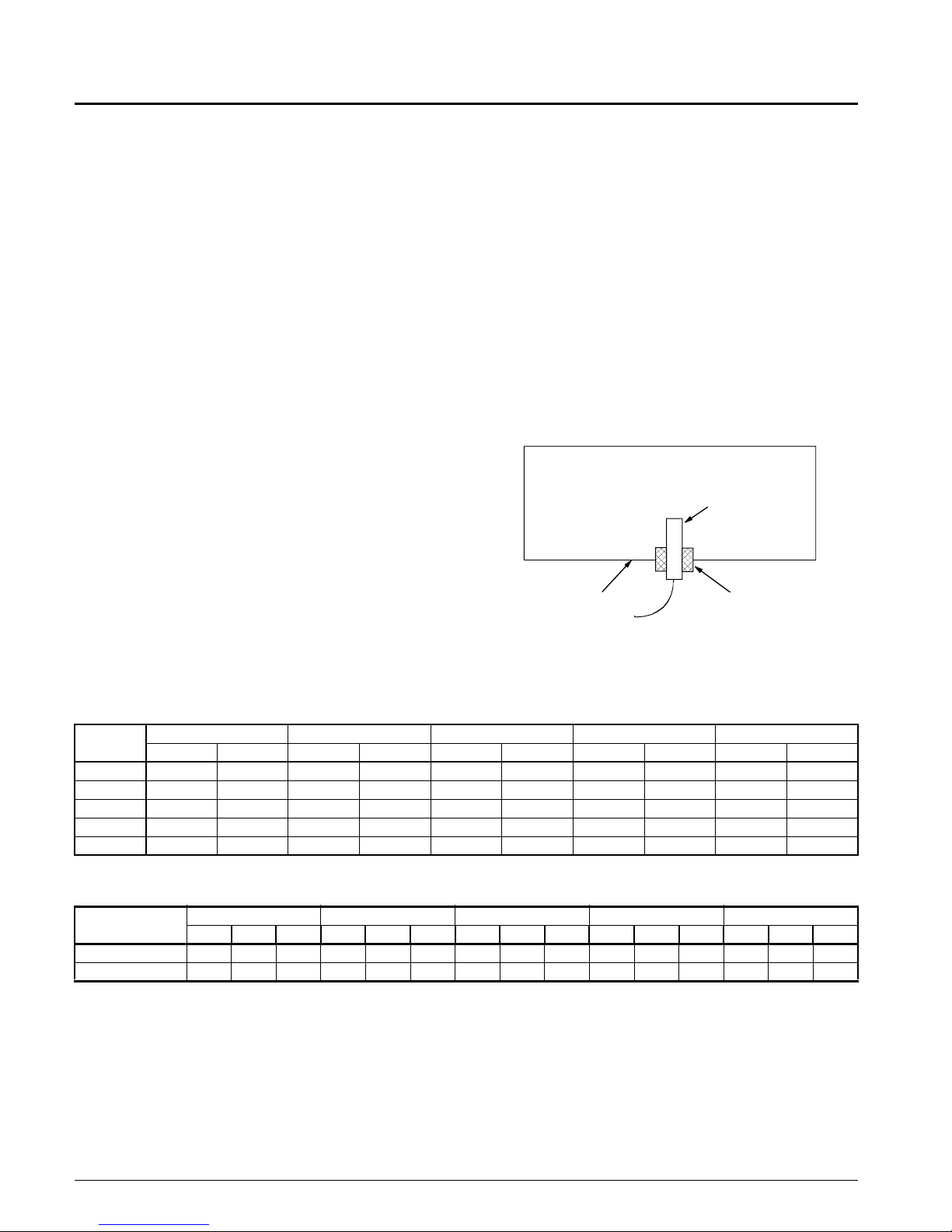
Mounting instructions (See Figure 28)
1. Drill hole in duct at remote sensing point and install a
rubber grommet. Insert sensing tube 1/8" into the duct
and securely clamp tubing to the duct, being sure not to
stress or kink the tubing. The end of the sensing tube
must be smooth and cut straight across. An angle cut
will affect operation.
2. Clamp a second tube to the outside of the duct at the
location of the sensing point.
3. Run both tubes along the ductwork and back to the unit.
The tubing may be routed to the pressure sensor (SPS1)
by drilling two holes through the unit upright post. A
grommet must be used at each hole to protect the tubing
and seal the cabinet.
Note: To avoid confusion between "high" and "low" tubing,
it is recommended that two different tubing colors be
used and that this information be recorded, along with
the sensing point location, on the master building blueprints.
4. Connect tubing to the high and low ports on the sensor.
Figure 28
Duct Static Pressure Sensor
All units provided with variable air volume control include a
factory mounted static pressure sensor (SPS1). The unit can
also have an optional second static pressure sensor, SPS2.
The sensor is factory wired and requires field installation of
1/4" I.D. sensor tubing to the selected duct location.
Note: Be sure that tubing complies with local code
requirements. Flame retardant plastic or metal tubing may be required. Carefully select the ductwork
sensing point for the pressure sensor. Improper
location of the sensing point will result in unsatisfactory operation of the entire variable air volume
system. The following guidelines should be adhered
to:
1. Sense near the end of long duct runs to ensure that all
terminal box take-offs along the run will have adequate
static pressure to operate.
2. The end of the sensing tube must be perpendicular to the
airflow in order to sense only static pressure.
28 IM708
Building Static Pressure Sensor
If a unit has direct building static pressure control capability,
static pressure taps must be field installed and connected to
pressure sensor SPS1 in the unit. This sensor is located on
the control panel.
The two static pressure sensing taps must be carefully
located and installed. Improper location or installation of the
sensing taps will cause unsatisfactory operation. Following
are pressure tap location and installation recommendations
for both building envelope and lab, or "space within a
space," pressure control applications. The installation must
comply with local code requirements.
Page 29

CAUTION
Condenser Water Flow Switch
Fragile sensor fittings. May damage pressure
sensor.
If tubing must be removed from a pressure sensor fitting, use care. Do not wrench the tubing
back and forth to remove or the fitting may break
off.
Building pressurization applications
1. Install a tee fitting with a leak-tight removable cap in
each tube near the sensor. This will facilitate connecting
a manometer or pressure gauge if testing is required.
2. Locate the building pressure (HI) tap in the area that
requires the closest control. Typically, this is a ground
level floor that has doors to the outside.
3. Locate the building tap so that it is not influenced by
any source of moving air (velocity pressure). These
sources may include air diffusers or outside doors.
4. Connect the tube to the 1/4 inch HI fitting on sensor
SPS1. Assure that the sensor does not support the
weight of the tubing; use tube clamps or some other
means.
5. Locate the reference pressure (LO) tap on the roof. Keep
it away from the condenser fans, waIls, or anything else
that may cause air turbulence. Mount it high enough
above the roof so that it is not affected by snow. If the
reference tap is not connected to the sensor, unsatisfactory operation will result.
6. Use an outdoor static pressure top (Dwyer A306 or
equivalent) to minimize the adverse effects of wind.
Place some type of screen over the sensor to keep out
insects. Loosely packed cotton works well.
7. Route the outdoor tap tube out of the main control panel
through a small field-cut opening in the edge of the control wiring raceway cover. Cut this "mouse hole" in the
vertical portion of the edge. Seal the penetration to prevent water from entering. Connect the tube to the 1/4
inch LO fitting on sensor SPS1.
Freezestat
A non-averaging type freezestat (FS1) is available to protect
hydronic coils from subfreezing temperatures. If the unit has
an economizer coil the control is mounted on the entering
face of the economizer coil. If the unit does not have an
economizer coil the control will be mounted on the leaving
face of the hot water coil. Upon sensing a hazardous temperature, the unit will shutdown, open hydronic control valves
and send an alarm indication via the MicroTech II controller.
The freezestat has a field adjustable setpoint range of 35°F to
40°F. The setpoint may be changed by turning the adjustment screw until pointer is opposite the desired cutout point.
The adjustment screw is accessible at the bottom of the control or at the top when the cover is removed.
A pressure differential type flow switch (WF1) is available
to verify flow to the unit condensers before compressor operation is allowed. The flow switch is factory installed in the
unit next to the condenser piping connections. If a loss of
condenser water flow is sensed, the cooling will be locked
out via the MicroTech II controller. When flow is restored,
the unit will automatically reset.
The factory settings for the water flow switch N.O. contacts
are as follows:
Unit Size Close Adj. Open Adj.
Ft. wc Range Ft. wc Range
018D-040D
045D-105D
3.0 +0.0 1.5 +0.5
-0.5 -0.5
4.5 +0.0 3.0 +0.5
-0.5 -0.5
Water Side Economizer
A completely factory installed, piped and controlled water
side economizer system is available on any constant or variable air volume system. Whenever the entering water temperature is more than 3°F (adjustable at the MicroTech II
keypad/display) below the mixed air temperature to the unit,
the control valves modulate to provide cooling directly from
the tower water. The economizer system can be used to provide 100% of the cooling demand or supplement mechanical
cooling by precooling the return air. The economizer system
consists of a water coil and two, two-way control valves. The
unit's MicroTech II controller will modulate the control
valves to satisfy the cooling demand whenever the entering
water is suitable. When the control valves are in the 90%
open position, the unit's compressors will be allowed to be
staged on to satisfy the cooling load. When the entering
water temperature is no longer suitable, the economizer control valve will close and the unit will be on 100% mechanical
cooling.
Two valve control arrangements are available from the factory. The first maintains full flow through the unit condensers at all times. This control arrangement is used for systems
with constant pumping systems. For installations with a variable pumping system, the control valves will be sequenced
such that flow is removed from the unit whenever cooling is
not required. A mechanical clutch is provided on each valve
to manually close or open the valves.
The economizer system is factory piped and the coil takes
advantage of the same drain pan and condensate connection.
Air may be vented from the economizer coil by using the
uppermost clean out plug. The torque requirement for the
cleanout plugs is 10 inch-lb.
IM708 29
Page 30

Condenser Water, Head Pressure
Control
An optional condenser head pressure control valve is available on units without water side economizer. This option
permits operation with entering water temperatures below
55°F . The valve is a two-way regulating valve controlled via
MicroTech II to maintain refrigerant head pressure .
Variable Inlet Vanes
An optional variable inlet vane assembly is available for
variable air volume applications. The assembly consists of
inlet funnels with integral sets of lever-actuated radial vanes,
one assembly for each side of the fan. The vanes, upon opening, direct air in the direction of wheel rotation.
The vanes rotate 90 degrees from closed to full open in
response to the factory installed actuator motor. The actuator
is controlled by the unit's MicroTech II controller. The inlet
vanes operate in unison and are properly adjusted and tested
before the unit leaves the factory. The start-up contractor
must check the adjustments and retighten all bolts and ball
joints to insure that shipping and handling has not caused
misalignment.
Adjustable Frequency Drive
As an option an adjustable frequency drive (AFD), is available for airflow modulation. A manually activated bypass
contactor is provided to allow system operation in the event
of drive service.
Static pressure is controlled by the unit mounted MicroTech
II controller. Indication of current airflow is available at the
MicroTech II controller. Static pressure is sensed by one or
two factory mounted duct sensors. The installer provides and
installs the sensor tubing from unit mounted sensor(s) to duct
location(s). The static pressure setpoint is keypad adjustable
through the MicroTech II DDC controller.
All variable air volume units include field adjustable duct
high limit safety control to protect ductwork from excessive
duct pressure.
Disconnect Switch
A factory mounted, nonfused main circuit interrupter for disconnecting the main electrical power is available. The switch
is located at the front of the unit on the control panel and is
accessible without unit penetration. The lug size information
is provided in Tables 11 and 12.
Dual Power Supply
The dual power block is an option for the power supply. This
allows the fan motor and control circuit to be isolated from
the compressor circuit. If the unit has the optional electric
heat it will be circuited with the compressors.
Electric Heat
Optional electric heat is available. Heat is controlled by the
unit's MicroTech II unit controller to maintain setpoint. The
heaters are factory installed and wired including branch fusing and all safety controls.
Hot Water Control
A factory mounted, 1 or 2 row hot water coil is available,
with or without factory mounted control valve. The hot
water control valve is controlled by the unit's MicroTech II
controller to provide morning warm-up heat or heat for constant volume application.
30 IM708
Page 31

System Check, Test and Start
WARNING
Electric shock hazard. Failure to bond the
frame of this equipment to the building electrical ground by use of the grounding terminal provided or other acceptable means may
result in electric shock. Disconnect electric
power before servicing equipment.
General
Only qualified personnel should perform the start-up and
service of this equipment. A representative of the owner or
the operator should be present during start-up to receive
instruction in the operation, care and adjustment of the unit.
To assure proper warranty coverage, the unit must be put
through a check, test and start-up procedure. The completed
check test and start form (supplied with each unit) must be
signed and returned to McQuay International.
Note: Always open power disconnect switch before open-
ing service panels.
Pre Start-up
1. Check that the unit is completely and properly installed
with ductwork connected. Check that all construction
debris is removed and filters are clean.
2. With all electrical disconnects open, check all electrical
connections to be sure they are tight. Although all factory connections are tight before shipment, some loosening may have resulted from shipping vibration.
3. Check all compressor valve connections for tightness to
avoid refrigerant loss at start-up. Although all factory
connections are tight before shipment, some loosening
may have resulted from shipping vibration. Refer to
Table 13 for proper valve torque values.
4. Check tightness of setscrews in bearings, drives, and fan
wheels. If retightening is needed, make certain fan
wheels are centered between the inlet openings and setscrews are torqued per Table 14.
5. Check that the fan rotates freely. Check belt tension and
alignment.
6. Check that the unit condenser water connections and
condensate drain connections have been made.
7. Before attempting to operate the unit, review the control
layout description to become familiar with the control
locations. Review all equipment service literature and
the unit wiring diagrams supplied with each unit.
Review optional controls to determine which are
included in the unit.
8. Make sure that the return air temperature sensor and
optional space temperature sensor, if used, have been
installed in the return air duct and that the wiring terminations have been made at the unit Input Board.
9. Make sure that entering and leaving condenser water
temperature sensors are mounted.
10. Make sure that the optional duct static pressure sensor is
connected to the duct with appropriate tubing. The unit
may have one optional static pressure sensor, SPS1. The
other option would be that or SPS1 and SPS2.
11. Check the voltage of the unit power supply and see that
it is within the ±10% tolerance that is allowed. Phase
voltage unbalance must be within ±2%.
12. Check the unit power supply wiring for adequate
ampacity and a minimum insulation rating of 75°C.
13. Verify that all mechanical and electrical inspections
have been completed per local codes.
14. Open the compressor suction and discharge shutoff
valves until backseated. Always replace valve seal caps.
15. The following must be done only for uni ts with 20 hp
compressors. Making sure unit switch S7 is in the
"OFF" position, throw the main power disconnect to
"ON." This will energize the crankcase heaters. Wait a
minimum of 24 hours before starting up the unit.
Table 13. Valve Torques
COUPLING
NUT SIZE
INCH
1.00 7±1 32±2 55+5
1.25 7±1 32±2 90+10
1.75 7±1 45±3 205+15
GAGE PORT
CAP TORQUE
LBS-FT
STEM CAP
TORQUE
LBS-FT
COUPLING
NUT TORQUE
LBS-FT
Table 14. Setscrew Torque
SETSCREW DIAMETER TORQUE MIN. (FT.-LBS.)
#10 4.3
1/4” 10.0
5/16” 20.0
3/8” 25.0
Start-up
General
All units are factory tested to assure proper operation in the
field.
1. Close disconnect switch with switch S7 in the "OFF"
position. Allow crankcase heaters to operate for 24
hours.
2. Power should now be supplied to the MicroTech II controller and the LEDs on MCB1 should follow the normal startup sequence.
IM708 31
Page 32

3. Set internal MicroTech II time clock or external time
clock if used.
4. Set cooling setpoint to a value which will assure a full
call for cooling.
5. Start the auxiliary equipment for the installation such as
water pumps, cooling towers, etc.
Fan start-up
1. Place the unit into the "FAN ONLY" mode through the
keypad:
System summary:
Control Mode:
Off
Auto
Heat/Cool
Heat only
Cool only
Fan only
2. Turn switch S7 to "ON". The supply air fan should start
and run.
3. Observe fan rotation. If fan is rotating backward,
reverse two legs of the main unit supply power. Unit
compressors are factory “phased” to match the supply
fan. Do not reverse internal fan motor power leads as
this will result in the compressor being out of phase. If
fan does not run:
a. Check the control circuit fuse F1.
b. Check control transformer fuse FB7.
c. Verify that the fan overload is not tripped.
d. Check the fan motor power fuses.
e. Trace the circuits.
Compressor start-up
With the supply air fan operational, prepare for compressor
operation. Note: The unit is shipped with the refrigeration
service valves closed. Backseat (open) the suction, discharge
and liquid line valves and replace service caps.
Connect service gauges and crack valves off the backseat
position (one turn forward). Verify that the unit has not lost
its refrigerant charge due to shipping damage or leaks. The
20 hp compressor have crankcase heaters that need to be verified they are operating. These should operate at least 24
hours before starting compressors.
1. Set Cooling Control Setpoint, menu 13, to a value which
will assure a call for full cooling.
2. Place unit into the “COOL ONLY” mode through key-
pad/display.
3. If desired, the MicroTech internal control timers can be
reduced to 20 seconds. The amount of time it operates in
this “Fast” mode can be entered through the keypad:
Setup/Service
Timer setting
Service
Note: "Fast" timers should only be used to verify
sequencing of compressors during start-up. The
timer must be returned to "Normal" for proper unit
operation.
Do not allow compressors to come on repeatedly in the
"Fast" timer mode as this may damage compressors and/or
will indicate "Motor Protector Failure" under compressor
alarms.
The compressors should now start. Start compressors one at
a time, beginning with compressor number 1. Facing the
unit, from left to right, compressors are numbered #1, #3, #4
and #2.
If the compressor motor hums but does not run, verify that
the unit is getting three phase power.
The compressors should run continuously. If a compressor
cycles on the low pressure switch:
a. Verify that the circuit is not low on charge.
b. Check for low airflow.
c. Check for clogged filters.
d. Check for restricted ductwork.
e. Check for very low mixed air temperatures to the unit.
f. Verify that all the distributor tubes, expansion valve and
liquid line components are feeding the evaporator coil.
g. Verify that all fan section access panels are in place.
h. Verify that the suction service valves and the liquid line
service valves are completely open.
i. Verify that all sensor inputs are connected.
Economizer start-up
The economizer is modulated to maintain the cooling setpoint. With entering water temperature more than 3°F below
the mixed air return to the unit, place the water sensor in a
cold bath if supply water to the unit is too warm, and the unit
calling for cooling, observe that the economizer control
valve modulates open. Readjust control setting or remove
the sensor from the bath and observe that the economizer
control valve drives closed.
Hot water start-up
The hot water valve is modulated to maintain the discharge
heating setpoint. To verify the hot water valve operation,
adjust the heating setpoint through the keypad:
Temperatures
Zone heating
OCC HTG SPT
Set the heating setpoint to a temperature greater than the
control temperature plus the dead band. Note the cooling setpoint must be higher than the heating setpoint. With the heating setpoint set properly the hot water valve should modulate
open. T o close the hot water valve adjust the heating setpoint
below the control temperature minus the dead band. After
testing the hot water valve, return the heating setpoint to its
proper setting.
Expansion valve superheat adjustment
It is very important that superheat is set properly. It should
be between 10°F and 12°F under full load conditions. Lower
entering air conditions, lower airflow rates and higher condensing temperatures reduce the load on the expansion
valve. Under reduced load conditions, the superheat could be
32 IM708
Page 33

as low as 6°F to 8°F. Insufficient superheat will cause liquid
floodback to the compressor and possible liquid slugging.
Excessive superheat will reduce system performance and
shorten compressor life. Verify that the sensing bulb is properly located (see Figure 23) and securely strapped to the
refrigerant line. Turn the adjusting stem clockwise to
increase superheat. Adjust the stem (maximum one turn at a
time) and observe the superheat. Allow up to 30 minutes for
the system to rebalance at the final setting.
Refrigerant Charge
Units are shipped with a full operating charge of refrigerant
and oil. However, in the event of a leak in the system, some
added charge may be required. If an undercharged situation
occurs, any of the following may be experienced:
1. If a circuit is slightly undercharged, bubbles will show
in the sightglass.
2. If a circuit is moderately undercharged, it may trip on its
frost protection sensor.
3. If the circuit is severely undercharged, it may trip on its
low pressure safety.
If any of these conditions occur, first identify and correct the
source of the leak and then follow the charging procedure
described below.
Using the liquid line sight-glass as the sole means of metering additional refrigerant charge into a self-contained unit, or
any AC unit, will not always provide the desired result.
Depending on the load conditions experienced by the equipment during the charging process, adding refrigerant until
the sight-glass is clear of all bubbles may over charge the
system and cause future operating issues. The better way to
charge a circuit is to use liquid sub-cooling and suction line
superheat as indicators, using the following procedure:
1. Verify that superheat is set per the System Check, Test
& Start procedures in this manual.
2. Measure the discharge pressure reading and convert it to
a discharge temperature.
3. Measure and record the circuit's liquid line temperature.
4. Measure and record the entering condenser water tem-
perature using the MicroTech II display.
5. Calculate liquid subcooling: subcooling = discharge
temperature - liquid line temperature
6. If the calculated subcooling value is less than 8ºF, refrig-
erant needs to be added.
7. Monitoring discharge pressure and liquid line temperature, add refrigerant until the discharge temperature
minus the liquid line temperature is equal to 8ºF ± 2ºF.
If the system is running at light load conditions, subcooling should be at the low end of the range. If the system is running near design conditions, subcooling
should be near the upper end of the range.
8. Verify that superheat is still in the prescribed range.
Following this method should prevent over charging of
the circuit.
Figure 29. Water and Refrigerant Piping Schematic
Note: Water Temperature Sensor to be installed by others
in field after the condenser water connections are
made.
IM708 33
Page 34

Variable air volume (VAV) start-up
Enter the duct static pressure setpoint value and parameters
through the keypad:
Air/Water Flow
Duct static pressure
Ducts tsp SPT
When the appropriate number of VAV terminal boxes are
opened by setting down there respective thermostats, the
vanes should go to the maximum airflow. Upon closing
enough VAV boxes by setting their respective thermostats
up, the inlet vanes should go to the minimum airflow position.
Rpm changes
All units are provided with fixed pitch sheaves selected for
the specified operating conditions. If a new fan rpm selection
is required a new sheave selection will need to be field
installed. Adjust belt tension as described below.
Drive sheave alignment and belt tension
Drive sheave alignment should be checked using the fourpoint method shown in Figure 30. When measuring from the
straight edge to the belt, the dimensions A, B, C and D must
be equal for correct alignment.
Check drive for adequate run-in belt tension. Use the following procedure to determine proper belt tension:
Step 1. Measure span length (t) as shown in Figure 31.
Step 2. From Figure 31, the deflection height (h) is always
1/64" per inch of span length (t). For example, a 32"
span length would require a deflection of 32/64" or
1/2".
Step 3. Determine the minimum and maximum recom-
mended pounds force using Table 14. Find the minimum recommended deflection force for the belt
section and type based upon the small sheave diameter. For intermediate sheave diameters and/or drive
ratio combinations, the minimum force may be interpolated.
Step 4. Using a spring scale, apply a perpendicular force to
any one of the belts at the midpoint of the span as
shown in Figure 31. Compare this value with the values found in Step 3.
a. If the value is below the minimum, the belts are
too loose and should be tightened.
b.If the value is higher, the belts are too tight and
tension should be decreased.
When new belts are installed, the initial tension will drop.
Check tightness of all setscrews on the fan hub, bearing
sleeves and retighten belts after 48 hours of operation.
Note: If after all tension adjustments, the belts slip or
squeal when starting, increase tension slightly and
replace the belts if they are worn or glazed.
34 IM708
Page 35

Final control settings
A
When all of the start-up procedures have been completed, set
the individual control parameters for operation.
1. Unit switch S7 to AUTO.
2. Heating/Cooling control parameters set as required.
3. Alarm limits set as required.
4. Night setback parameters set as required.
5. Duct static pressure, building static pressure, as
required.
6. Economizer control parameters set as required.
7. Control timers set as required.
8. Date and time set as required.
9. Operating schedule set as required.
10. Holiday schedule set as required.
Note: See Operation manual per Table 1 on page 3, for the
keypad menu structure.
Maintaining control parameter records
After the unit has been checked, tested and started and the
final control parameters are set, the final settings should be
recorded and kept on file. This file should be updated whenever changes are made to the control parameters. This will
facilitate any required analysis and troubleshooting of the
system operation.
Figure 30. Drive Alignment
FIELD SUPPPLIED STRAIGHTEDGE
BCD
Figure 31. Belt Tension
Table 15. Recommended Pounds Force Per Belt
BELT
SECTION
A
B
BX
5VX
SMALL SHEAVE
DIA. (IN)
3.0 - 3.6 3.00 4.25
3.8 - 4.8 3.5 5.00
5.0 - 7.0 4.00 5.50
3.4 - 4.2 4.00 5.50
4.4 - 5.6 5.13 7.13
5.8 - 8.6 6.38 8.75
3.4 - 5.6 6.50 9.13
4.4 - 5.6 6.50 9.13
5.8 - 8.6 7.38 10.13
4.7 - 6.7 10.00 15.00
7.1 - 10.8 12.88 18.75
11.8 - 16.0 15.00 22.00
MINIMUM MAXIMUM
IM708 35
Page 36

System Maintenance
WARNING
Installation and maintenance are to be performed only by qualified personnel who are
familiar with local codes and regulations, and
are experienced with this type of equipment.
WARNING
Moving machinery and electrical power hazards. May cause severe personal injury or
death.
Disconnect and lock off power before servicing
equipment.
.
CAUTION
Sharp edges are inherent to sheet metal
parts, screws, clips and similar items. May
cause personal injury.
Exercise caution when servicing equipment.
Preventative Maintenance
Preventative maintenance is the best way to avoid unnecessary expense and inconvenience. Have this system inspected
at regular intervals by a qualified service technician. The
required frequency of inspections will depend on installation
and operating duty. Routine maintenance should cover the
following items:
1. Tighten all belts, setscrews, and wire connections. (See
table 14, page 31.)
2. Clean evaporator or economizer coils mechanically or
with cold water, if necessary. Usually any fouling is
only matted on the entering air face of the coil and can
be removed by brushing.
3. Clean condenser and economizer tubes on a periodic
basis. Condenser and economizer coils can be cleaned
chemically or mechanically . T ubing should be kept clean
to maintain system performance.
4. Lubricate motor and fan shaft bearings.
5. Align or replace belts as needed.
6. Replace filters as needed.
7. Check refrigerant sightglass. Check for refrigerant leaks
if sightglass is not solid with steady-state full load operation of unit. (Note: A partially full sightglass is not
uncommon at part load conditions. Check for proper
superheat.)
8. Check for blockage of condensate drain. Clean conden-
sate pan as needed.
9. Check power and control voltages.
10. Check running amperage.
11. Check operating temperatures and pressures.
12. Check and adjust temperature and pressure controls.
13. Check and adjust linkages.
14. Check operation of all safety controls.
15. Lubricate door latch mechanisms.
Motor Bearings
Fan motors should have grease added after every 2,000
hours of operation. Relubricate while motor is warm and at a
standstill. Remove and clean upper and lower grease plugs,
insert grease fitting into upper hole adding a small amount of
clean grease with a low pressure gun. Run motor for five
minutes before replacing plugs.
Note: Specific greasing instructions are to be found on a
tag attached to the motor. If special lubrication
instructions are shown on the motor nameplate,
they will supersede all other instructions.
CAUTION
Bearing overheating potential. Can cause damage to the equipment.
Do not overlubricate. Use only a high grade mineral
grease with a 200°F safe operating temperature.
Refer to unit lubrication instruction label for specific
lubricants
36 IM708
Page 37

Replacement Parts
Description McQuay Part
Number
Zone temperature sensor with tenant override 111048101
Outside air temperature sensor 060004703
Airflow proving switch 060015801
Discharge air temperature sensor 060004702
Return air temperature sensor 060004703
Freeze stat 072502001
Filters
Unit Size Filter Size Qty
Part Number
2"-35% 4"-35% 4"-65% 4"-85%
018-028 20 x 20
20 x 25
035-040 20 x 25 10 072407704 072402304 072405704 072405704
045-055 20 x 25 12 072407704 072402304 072405704 072405704
065 20 x 20 18 072407703 072402303 072405703 072407603
070 16 x 20
20 x 25
080 20 x 20
20 x 25
095 16 x 20
20 x 25
16 x 20
105
16 x 25
20 x 25
12
15
15
17
6
2
6
3
6
4
1
072407703
072407704
072407701
072407704
072407703
072407704
072407701
072407704
072407701
072407702
072407704
072402303
072402304
072402301
072402304
072402303
072402304
072402301
072402304
072402301
072402302
072402304
072405703
072405704
072405701
072405704
072405703
072405704
072405701
072405704
072405701
072405702
072405704
072407603
072407604
072407601
072407604
072407603
072407604
072407601
072407604
072407601
072407602
072407604
IM708 37
Page 38

Service and Warranty Procedure
In Warranty Return Material
Procedure
Material may not be returned except by permission of authorized factory service personnel of McQuay International at
Minneapolis, Minnesota.
A "return goods" tag will be sent to be included with the
returned material. Enter the information as called for on the
tag in order to expedite handling at our factories and prompt
issuance of credits. All parts shall be returned to the factory
designated on the return goods tag, transportation charges
prepaid.
The return of the part does not constitute an order for
replacement. A purchase order for the replacement part must
be entered through your nearest McQuay representative. The
order should include part number and description, and the
model and serial numbers of the unit involved.
Following inspection of the returned part by our personnel
and if it is determined that the failure is due to faulty material
or workmanship, credit will be issued on customer's purchase order.
Replacement Parts
When writing to McQuay for service or replacement parts,
refer to the model number, serial number, and G.O. number
of the unit as stamped on the serial plate attached to the unit.
For questions regarding wiring diagrams, it will be necessary
to provide the number on the specific diagram. If replacement parts are required, mention the date of installation of
the unit and the date of failure, along with an explanation of
the malfunction and a description of the replacement parts
required.
Product Warranty
McQuay International, hereinafter referred to as the "Company," warrants that it will provide, at the Company's option,
either free replacement parts or free repair of component
parts in the event any product manufactured by the Company
and used in the United States proves defective in material or
workmanship within twelve (12) months from initial start-up
or eighteen (18) months from the date shipped by the Company, whichever comes first. For additional consideration,
the Company warrants that for four (4) years following the
initial warranty period it will provide, at the Company's
option, free replacement parts for the motor-compressor, or,
free replacement for any integral component of the motorcompressor which provides defective in material or workmanship. (Extended warranties for motor-compressors are
not applicable unless separately purchased.)
To obtain assistance under the parts warranty or extended
motor-compressor warranty, simply contact the selling
agency. To obtain information or to gain factory help, contact McQuay International, Warranty Claims Department,
P. O. Box 155 1, Minneapolis, MN 55440; telephone (763)
553-5330.
This warranty constitutes the buyer's sole remedy. It is
given in lieu of all other warranties. There is no implied
warranty of merchantability or fitness for a particular
purpose. In no event and under no circumstances shall
the Company be liable for incidental or consequential
damages, whether the theory be breach of this or any
other warranty, negligence or strict tort.
This parts warranty and the optional extended warranties
extend only to the original user. Of course, abuse, misuse, or
alteration of the product in any manner voids the Company's
warranty obligation. Neither the parts or extended warranty
obligates the Company to pay any labor or service costs for
removing or replacing parts, or any shipping charges. Refrigerant fluids, oils, and expendable items such as filters are not
covered by this warranty.
The extended warranties apply only to integral components
of the motor-compressor or heat exchanger, not to refrigerant
controls, electrical controls, or mechanical controls, or to
failures caused by failure of those controls.
Attached to this warranty is a requirement for equipment
containing motor-compressors and/or furnaces to report
start-up information. The registration form accompanying
the product must be returned to McQuay International within
ten (10) days of original equipment start-up. If that is not
done, the date of shipment shall be presumed to be the date
of start-up and the warranty shall expire twelve (12) months
from that date.
No person (including any agent, salesman, dealer, or distributor) has authority to extend the Company's obligation
beyond the terms of this express warranty, or to state that the
performance of the product is other than that published by
the Company.
38 IM708
Page 39

Check, Test and Start Procedure Form
Compressorized Equipment Warranty Registration Form:
This form must be filled out and returned to McQuay, Warranty
Department, within 10 days in order to comply with the terms of
McQuay Warranty.
Check, Test and Start Procedure for SWP/SWT (Self-contained Air Conditioning Systems)
Job Name: McQuay G.O. No.:
Installation Address:
City: State:
Purchasing Contractor:
City: State:
Unit Model No.: Serial No.:
Compressor No. 1 Serial No.
Compressor No. 3 Serial No. Compressor No. 4 Serial No.
Compressor No. 5 Serial No. Compressor No. 6 Serial No.
Mark N/A on all items not applying to the type of the unit. See IM Bulletin for more information. Any additional comments
may be made on a separate sheet of paper and attached to this form.
Compressor No. 2 Serial No.
INITIAL CHECK
A. Is any shipping damage visible? Yes No
B. Is unit installed level? Yes No
C. Is unit positioned to provide adequate free area for service and operation? Yes No
D. Are fan drives properly aligned and belts adjusted? Yes No
E. Does fan turn freely? Yes No
F. Tightened all setscrews on pulleys, bearings and fans? Yes No
G. Have the Condenser Water Temperature Sensors been located correctly? Yes No
H. Has the Installing Contractor installed the Return Air Temperature Sensor
in the Return Air stream? Yes No
I Has the Installing Contractor installed the high & low Static Pressure Sensor
tubing in the ductwork? Yes No
J. Does electrical service correspond to unit nameplate? Yes No
K. Adequate disconnect and circuit protectors installed? Yes No
L. Is the unit adequately grounded? Yes No
M. Are all electrical power connections tight? Yes No
N. Have the compressor heaters operated continuously for 24 hours prior to start up? Yes No
O. Does all electrical wiring conform to unit electrical diagram? Yes No
P. Does all field wiring conform to electrical diagrams? Yes No
Q . Are all service valves open? Yes No
R. H a ve all the ship ping hold-down plates securing the fan frame been removed? Yes No
S. Unit with ducted return, has the low side tubing for PC5 (dirty filter switch) been
Installed? Yes No
T. Are all the cleanout plugs installed (condenser, condensate trap & optional
waterside economizer)? Yes No
IM708 39
Page 40

START-UP
A. Does the unit start & perform per sequence of operation as stated in IM Bulletin? Yes No
B. D oes the fan rotate in the right direction ? Yes No
C. Condenser inlet water temperature Deg. F _____
D. Condenser outlet water temperature Deg. F. _____
E. Number of Compressors Operating Deg. F. _____
F. Return air temperature Deg. F . _____
G. Mixed air temperature Deg. F. _____
H. Supply air temperature Deg. F. _____
I. Compressor Readings:
Reading
Compressor #1Compressor #2Compressor #3Compressor #4Compressor #5Compressor
Suction Pressure, psig
Discharge Pressure, psig
Superheat Setting @ TXV
Bulb, Deg. F
Compressor RLA (name
plate)
Current, Line L1, amps
Current, Line L2, amps
Current, Line L3, amps
J. Electrical Heat Readings (When installed):
#6
FLA amps (nameplate)
Reading
@ Contactor M11 @ Contactor M12 @ Contactor M15 @ Contactor M16
Current, Line Ll, amps
Current, Line L2, amps
Current, Line L3, amps
40 IM708
68KW Heat, 230v or 208v Only
Page 41

K. Fan Motor Current Per Phase: amps amps amps
FLA: amps
Variable Frequency Drive: % Speed / Hertz
L. Fan Speed: rpm at above frequency
M. Unit Voltage across each phase: volts volts volts
N. Unit Current per phase: amps amps amps
CONTROL CHECK
A. Compressor Low and High Pressure Cut-outs:
Comp. No. 1 Comp. No. 2 C o mp. No. 3 Comp. No. 4
Low Press Cut-out, psig
Low Press Cut-in, psig
High Press Cut-out, psig
Comp. No. 5 Comp. No. 6
Low Press Cut-out, psig
Low Press Cut-in, psig
High Press Cut-out, psig
GENERAL
A. Are all control lines secure to prevent excessive vibration and wear? Yes No
B. Are all gauge ports shut off, valve caps and packings tight after start-up? Yes No
C. Are VAV boxes set to keep a minimum airflow of 40% of design? Yes No
D. Do the Economizer, Water Regulating, and Hot Water valves rotate freely? Yes No
Performed By: Title:
Signature: Date of Start-up:
RETURN COMPLETED FORM TO:
McQuay International
Warranty Department
13600 Industrial Park Boulevard
Minneapolis, MN 55441
Comments:
IM708 41
Page 42

Page 43

Page 44

13600 Industrial Park Boulevard, Minneapolis, MN 55441 USA (763) 553-5330
 Loading...