

Page 1
Installation & Maintenance Data
IM 368-7
Group: PTAC
Part No.: 106018472
Date: November 2003
Suite™ Incremental
®
PTAC/PTHP Conditioner
©2003 McQuay International
®
Page 2
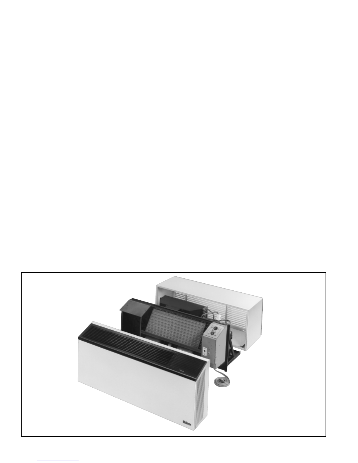
Table of Contents
Installation ......................................................................... 2
Inspection..........................................................................2
Nomenclature....................................................................3
Wall Opening Requirements .............................................3
Wall Sleeve Installation
Frame & Brick ............................................................4
Panel Wall Construction.............................................5
Thick Wall Construction .............................................6
Wall Sleeve Extension
Louver Frame.............................................................7
Subbase Installation..........................................................8
Installation of Optional Condensate Drain Kit ................... 9
Installation of Louvers .....................................................10
Installation of Chassis .....................................................10
Adjusting Temperature Limiting Device........................... 11
Electrical Service............................................................. 1 1
Equipment Startup .......................................................... 11
Remote Mounted Thermostat ......................................... 12
Scheduled Maintenance .................................................12
Recommended Spare Parts............................................13
Refrigeration Cycle .........................................................13
Troubleshooting Chart...............................................14, 15
Approximate Shipping Weights ....................................... 15
Wiring Diagrams............................................16, 17, 18, 19
Installation
The installation of this equipment shall be in accordance with the regulations of authorities having jurisdiction and all
applicable codes. It is the responsibility of the installer to determine and f ollow the applicable codes. Sheetmetal parts, sel ftapping screws, clips and such items inherently have sharp edges, and it is necessary that the installer exercise caution.
This equipment is to be installed only by an experienced installation company which employs trained personnel.
Inspection
When the equipment is received all items should be carefully
checked against the bill of lading to be sure all crates and
cartons have been received. All units should be carefully inspected
for damage when received. If any damage is noticed, the carrier
should make the proper notation on the delivery receipt acknowledging the damage. The carrier should also fill out a Carrier
Inspection Report. The McQuay International Traffic
Department should then be contacted.
The unit nameplate should be checked to make sure the
voltage agrees with the power supply available.
Suite II Series Comfort Conditioner is designed and built for
through-the-wall installation in either new or existing buildings
The self-contained refrigerant system delivers cooling to the desired space. Heating can be accomplished with electric
resistance, hydronic or with reverse cycle heating options.
Each conditioner consists of the following components:
1. Heating/Cooling Chassis — Shipped separate.
2. Cabinet/Wall Sleeve — Shipped separate.
3. Outdoor Louver — Shipped in a separate carton.
4. Subbase (not shown) — Optional on all 208V and 230V
heat pump and electric heat units. Standard for all 265V
and for hydronic heater option. Shipped in a separate
carton.
Figure 1. Exploded View of Complete Unit (Shown Without Subbase)
IM 368 / Page 2 of 20 (Rev 11/03)
Page 3
MCQUA Y PT AC/PTHP
P DES 1 009 E Z 60
Product Category
P = PTAC
Product Identifier
see box below (Suite)
Design Series
1 = A Design
Nominal Capacity
007 = 7,000
009 = 9,000
012 = 12,000
015 = 15,000
McQuay PTAC/PTHP Product Identifiers
DEA = Suite II, 2 motor, automatic damper
DEC = A/C & Elec/Hyd Htg Chassis w/Corr. Protection
DEH = Suite II, 2 motor, hydronic w/standby
DEI = Suite II, 2 motor, IAQ
DES = A/C & Heating (Elec/Hyd) Chassis
DHA = Suite II, 2 motor, heat pump, automatic damper
DHC = H/P w/ Electric Heat & Corrosion Protection
DHI = Suite II, 2 motor, heat pump, IAQ
DHS = H/P w/ Electric Heat
Heating Options
35 = 2.5 kw
41 = 3.5 kw
48 = 5.0 kw
62 = Hydronic, normally open
63 = Hydronic, normally closed
Coil Options
(None)
Voltage
A = 115 - 60 - 1
C = 208 - 60 - 1
J = 265 - 60 - 1
SEA = A/C w/Electric Heat & Automatic OA Damper
SEC = A/C w/Electric Heat & Corrosion Protection
SEH = A/C w/Hydronic Heat & Standby
(Emergency) Power
SEI = A/C w/Electric Heat & IAQ Power Vent Kit
SES = A/C & Heating (Elec/Hyd) Chassis
SHA = A/P w/Electric Heat & Automatic OA Damper
SHC = H/P w/ Electric Heat & Corrosion Protection
SHI = H/P w/ Electric Heat & IAQ Power Vent Kit
SHS = H/P w/Electric Heat
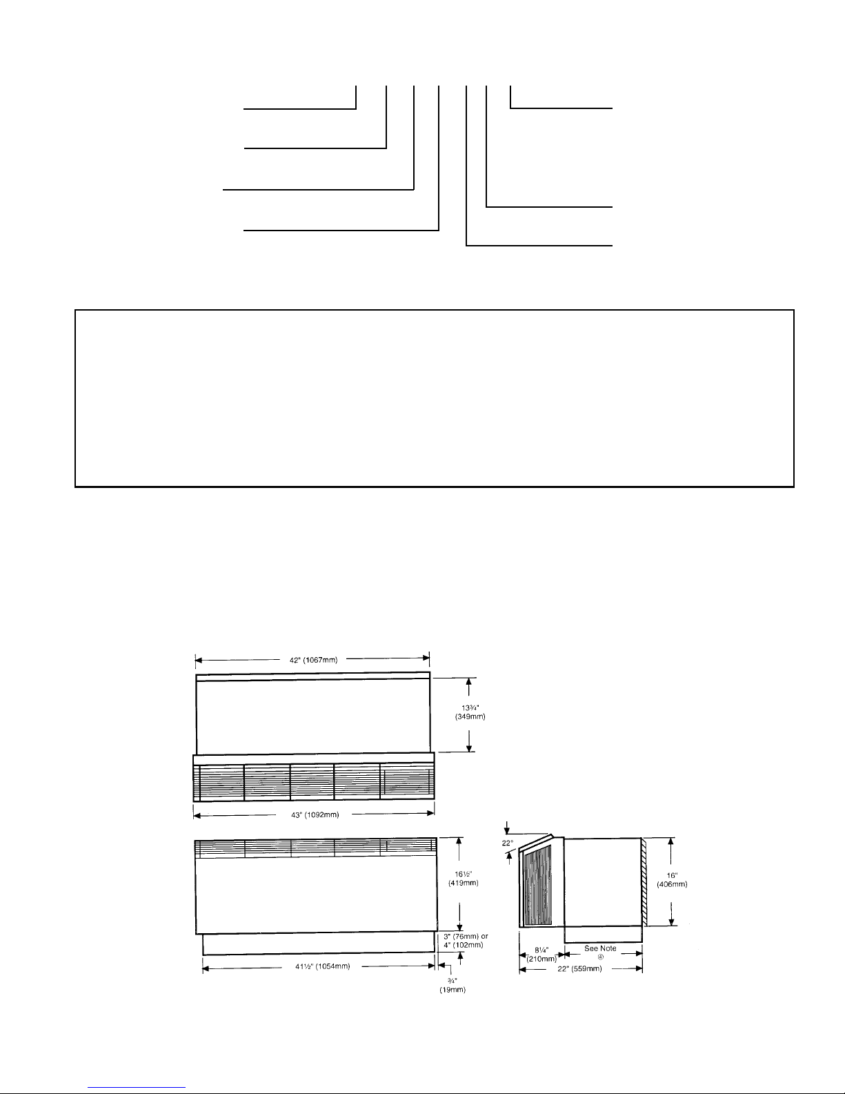
Wall Opening Requirement
Before installing the unit, check the wall opening to be sure the
cabinet/wall sleeve will slide into the opening unobstructed. For
masonry walls, a lintel must be used to provide support over each
opening. The rough opening should measure 16
1
42
/4" (1073mm) wide (see note ➂). When no subbase is used,
the opening should be a minimum of 3" (76mm) off the floor . This
Figure 2. Suite Unit with Electric Subbase
1
/4" (413mm) X
distance may vary when a subbase is supplied. The standard
subbase is available in 3" (76mm) or 4" (102mm) heights. For
units with hydronic heat, the subbase is 81/4" (210mm). Each
subbase has leveling legs providing for up to 1" (25.4mm)
additional height.
Notes:
➀ Unit pictured with subbase installed. Subbase is optional on 208V and 230V units. Subbase is standard on all 265V units and units with hydronic heat.
➁ Subbase extends to front edge of unit when furnished with hydronic heat.
➂ Opening needs to be 16
④ Subbase side channels are adjustable from 43/8" to 133/4" (111mm to 349mm).
5
/8" (422mm) x 425/8" (1083mm) when using a louver frame. See page 7.
IM 368 / Page 3 of 20 (Rev. 11/03)
Page 4
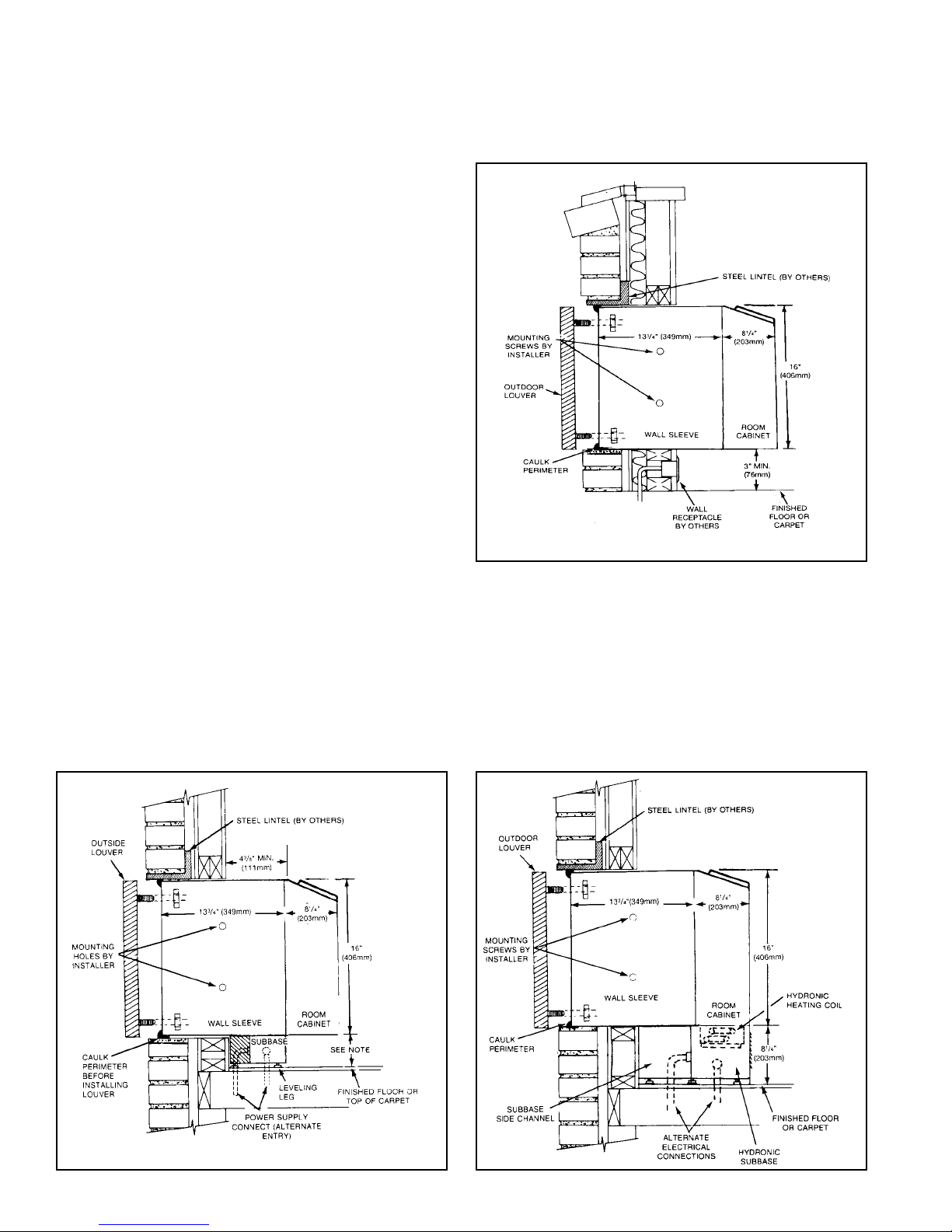
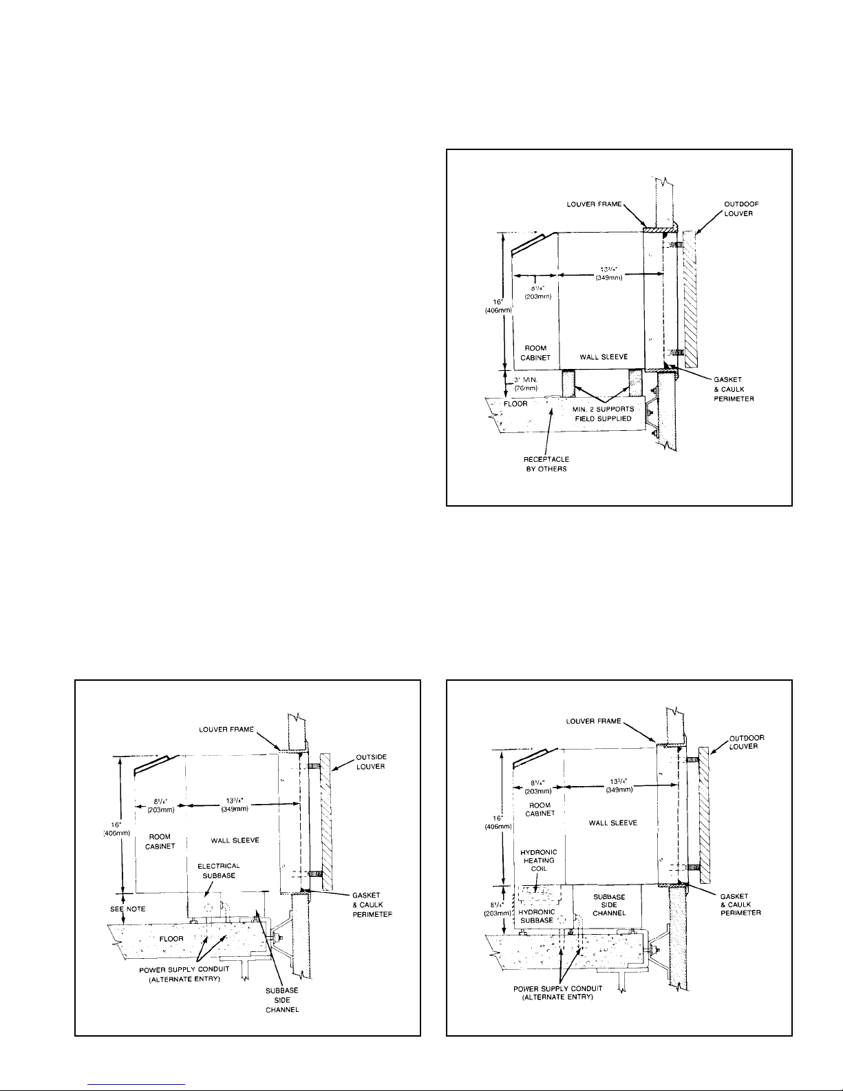
Wall Slee ve Installation — Frame and Brick
A heavy-gauge, corrosion resistant cabinet/wall sleeve is provided for each unit. The cabinet/wall sleeve is either shipped in a separate
carton, shipped in a multi-pack of 15 or in a single carton with the heating/cooling chassis.
The standard cabinet/wall sleeve is designed to be easily installed
in a variety of wall constructions. Note: The center of gravity is
1
10
/4" (260mm) from the rear face of the wall sleeve. The wall
sleeve must be inserted into the wall at least 101/4" (260mm) or
other support must be employed. Support can be from a factory
supplied subbase or from other field supplied materials.
Recommended installation procedures are described below.
1. Clean the opening of all debris that may interfere with
installation.
2. If the unit is to be supplied with a subbase, refer to page 8 for
installation procedures. Install subbase before installing
cabinet/wall sleeve.
3. If the optional drain kit is to be employed (heat pump only),
refer to page 8 before proceeding.
4. Place a thin pad of soft mortar on the bottom of the opening
and slide in the cabinet/wall sleeve. Be sure to recess the wall
sleeve enough to accommodate outside louver. This recess
3
is
/8" (9.5mm) for stamped louvers and 11/4" (32mm) for
architectural louver. Louver should be flush to exterior
surface when complete. Note: The wall sleeve is not intended
to replace the lintel.
5. Level cabinet/wall sleeve in both directions and secure by
anchoring with appropriate fasteners (as shown in Figure C,
page 7). A
5
/16" (8mm) hole is provided on each side, 2" (51mm)
down from the top and 2" (51mm) in from the rear of the
cabinet/wall sleeve. Additional holes may be required to firmly
secure the cabinet/wall sleeve. Caution: Do not drill holes
in the base of the cabinet/wall sleeve. Where a subbase is
used, secure wall sleeve to subbase with clips provided.
6. Caulk the cabinet/wall sleeve to the wall opening on both the
inside and outside perimeter. Be careful not to plug the weep
holes. Caulking should be resilient, non hardening type such
as silicone.
Figure 3. Frame & Brick with Cord Connection
Figure 4. Frame & Brick with Standard Electrical Subbase
IM 368 / Page 4 of 20 (Rev 11/03)
Figure 5. Frame & Brick with Hydronic Subbase
Page 5
Wall Sleeve Installation — Panel Wall Construction
For panel wall and thin wall construction, it is recommended that a louver frame be used. Refer to page 7 for installaton of louver frame
before continuing.
Panel wall and thin wall construction varies only slightly from frame
and brick construction. Note: The center of gravity is 10
1
/4"
(260mm) from the rear face of the wall sleeve. The wall sleeve
must be inserted into the wall at least 10
1
/4" (260mm) or other
support must be employed. Support can be from a factory supplied subbase or from other field supplied materials. Installation
for this application is as follows:
1. Clean the opening of all debris that may interfere with in-
stallation.
2. If the unit is to be supplied with a subbase, refer to page 8 for
installation procedures. Install subbase before installing cabinet/wall sleeve.
3. If the optional drain kit is to be employed (heat pump only),
refer to page 9 before proceeding.
4. Be sure the cabinet/wall sleeve is mechanically attached to
the wall and caulked to assure a proper seal. It is recommended that the louver frame be used for this purpose. (See
Figure B, page 7.)
5. Recess the wall sleeve so that the louver is flush with the
exterior of the building.
6. Level cabinet/wall sleeve in both directions and secure by
anchoring with appropriate fasteners (as shown in Figure C,
page 7) or drill additional holes as required to secure firmly.
Caution: Do not drill holes in the base of the cabinet/wall
sleeve. Where a subbase is used, secure wall sleeve to sub-
base with clips provided.
7. If no subbase is employed, proper support by installer must
be provided under wall sleeve, as shown in Figure 6.
8. Caulk the cabinet/wall sleeve to the wall opening on both the
inside and outside perimeter. Be careful not to plug the weep
holes. Caulking should be resilient, non-hardening type such
as silicon.
Figure 6. Panel Wall Construction with Cord Connection
Figure 7. Panel Wall Construction with Standard Electrical
Subbase
Figure 8. Panel Wall Installation with Hydronic Subbase
IM 368 / Page 5 of 20 (Rev. 11/03)
Page 6
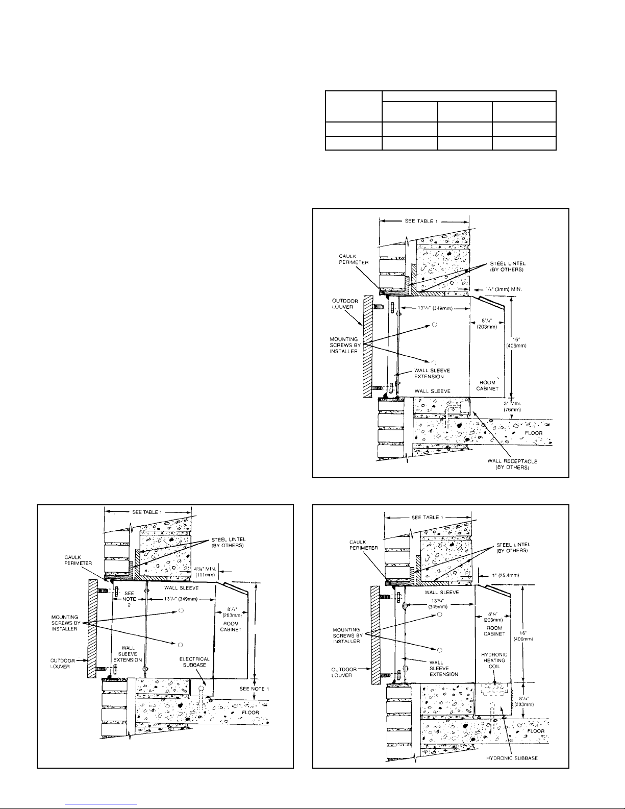
Wall Sleeve Installation — Thick Wall Construction
Installation of cabinet/wall sleeves for thick walls requires special
consideration. Table 1 should be used to determine the
maximum wall thickness allowed for the standard cabinet/wall
sleeve. For thicker walls, cabinet/wall sleeve extensions are
available from your representative. Refer to page 7 for proper
installation of cabinet/wall sleeve extensions.
Cabinet/wall sleeve installation in thick walls is similar to frame
and brick installation. Install as follows:
1. Clean the opening of all debris that may interfere with
installation.
2. If the unit is to be supplied with a subbase, refer to page 8 for
installation procedures. Install subbase before installing
cabinet/wall sleeve.
3. If the optional drain kit is to be employed (heat pump only),
refer to page 9 before proceeding.
4. If wall thickness exceeds dimensions shown in Table 1, a
cabinet/wall sleeve extension must be used. Install the
extension as described on page 7. Once the extension is
attached to the cabinet/wall sleeve, place a thin pad of soft
mortar on the bottom of the opening and slide in the wall
sleeve/extension assembly . Be sure to recess the wall sleeve
3
enough to accommodate outside louver. This recess is
/8"
(9.5mm) for stamped louvers and 11/4" (32mm) for architectural louvers. Louver should be flush to exterior surface when
completed. Note: The wall sleeve is not intended to replace
the lintel.
5. Level cabinet/wall sleeve in both directions and secure by
anchoring with appropriate fasteners (as shown in Figure C,
page 7) or drill additional holes as required to secure firmly.
Caution: Do not drill holes in the base of the cabinet/wall
sleeve. Where a subbase is used, secure wall sleeve to sub-
base with clips provided.
6. Caulk the cabinet/wall sleeve to the wall opening on both the
inside and outside perimeter. Be careful not to plug the weep
holes. Caulking should be resilient, non-hardening type such
as silicone.
Table 1. Maximum Wall Thickness without Sleeve Extensions
Maximum Wall Thickness
Louver Type
Stamped
Architectural
No
Subbase
14" (356mm)
147/8" (378mm)
Standard
Subbase
1
/2" (241mm)
9
3
10
/8" (264mm)
Hydronic
Subbase
1
/8" (333mm)
13
14" (356mm)
Figure 9. Thick Wall Construction with Cord Connection
Figure 10. Thick Wall Construction with Standard Electric
Subbase
Note: 1. Subbase is available in 3" (76mm) or 4" (102mm) height. Leveling legs provide for
adjustment of 1" (25.4mm).
2. Wall sleeve extension is available in various depths and supplied as required.
IM 368 / Page 6 of 20 (Rev 11/03)
Figure 11. Thick Wall Installation with Hydronic Subbase
Page 7

Wall Slee ve Extensions
The standard cabinet/wall sleeve will accommodate a maximum
wall thickness described in T able 1. For thicker walls, cabinet/wall
sleeve extensions are available from your local representative.
When it is supplied by the representative, it is treated for
maximum corrosion resistance and matched to the exact size of
the standard wall sleeve. Field fabricated wall sleeve extensions
should also be treated and matched to the standard wall sleeve.
Be sure to provide air splitters to prevent recirculation of
condenser air. Air splitters should be placed in the wall sleeve as
shown in Figure A. It is important that spacing of the air splitters
match exactly those dimensions shown in Figure A.
Installation
Wall sleeve extensions are shipped in a separate carton and
tagged to match the proper unit. Be sure to check tagging of the
extension against that of the unit. Install the wall sleeve
extension as follows:
1. Position the extension with standard cabinet/wall sleeve so
proper alignment with drain and mounting holes is achieved.
2. Place a bead of caulk around the perimeter of the wall sleeve
and another bead around the mating side of the wall sleeve
extension so that the joint is watertight. Be sure to use a
resilient caulking such as silicone.
3. Assemble the wall sleeve extension to the wall sleeve. Clean
out weep holes to assure proper drainage.
4. Attach indoor drain kit (if used) according to the instructions
on page 9. Outdoor drain kits must be installed after wall sleeve
is in place.
5. Continue wall sleeve installation according to instruction #4
on page 6.
Figure A. Wall Sleeve Extension
Figure B. Louver Frame
Louver Frame
Louver frames should be used for panel wall and thin wall
applications to assure positive anchoring to the wall. Recess the
cabinet/wall sleeve so that the louver is flush with the outside of
the building. Place louver frame around cabinet/wall sleeve as
shown in Figure B. Be careful not to drill holes in the bottom of
the wall sleeve. Secure angles at sides and top of walls.
Anchoring
Anchoring the cabinet/wall sleeve in the opening is accomplished
as shown in Figure C. Be sure not to drill holes in the bottom as it
will cause leaks. It is recommended that rubber isolation washers
be used with the fasteners to minimize sound transmission from
the equipment to the wall, at the point of contact.
Figure C. Anchoring Methods
IM 368 / Page 7 of 20 (Rev. 11/03)
Page 8

Subbase Installation
Electric Subbase
An electrical subbase is optional for all 208V and 230V units. A
subbase is standard for all 265V units. The standard subbase is
available with 3" (76mm) or 4" (102mm) heights. The subbase
contains leveling legs for adjustment of up to 1" (25mm)
additional height. All subbases are factory supplied.
Installation
Install the subbase as follows:
1. If the minimum depth subbase is required, discard the side
extension pieces.
2. If more than the minimum depth is required, determine the
depth of the side extension pieces desired and break at the
Figure 12. Standard (Electric) Subbase
proper score line. Insert the extension pieces into the front
assembly and secure with two short black screws at
each side.
3. Insert leveling bolts into subbase bottom flange. Four (4) bolts
will be needed if side extensions are used. Only two (2) bolts
are required if side extensions are not used.
4. Place the subbase on the floor and align its center line with
the center line of the wall opening. Do not fasten the subbase
to the floor. Attach the subbase to the cabinet wall sleeve
using clips provided with the subbase.
5. The wiring should be roughed in and the conduit connected
to the subbase junction box. Complete the installation by
wiring the receptacle to the incoming power supply .
Electrical
3" x 5"
(76 to 127mm)
Opening for
Electrical and/or
Drain Rough-In
Knockouts for
Opitonal Fuse &
Disconnect Switch
Junction
Box for Main
Power Connection
Receptacle (Req’d
on 265V Units)
Plug/Cord Cover
(Req’d on 265V
Units)
Hydronic Subbase
A subbase is supplied as standard with all hydronic units. This
subbase measures 8" (203mm) in height and includes the
hydronic heating coil. Refer to IM Bulletin 419 for installation
Figure 13. Hydronic Subbase
Receptacle (Factory installed
As Req'd
1
8
3/4"
21/2"
/4"
3" x 5" Opening for Electrical
and/or Piping Rough-in
15"
5
/8" O.D. Copper Sweat
Top View
when fuse & disconnect are
furnished)
21/2"
7
⁄8"
5
⁄8"
3"
21⁄2"
5"
Leveling Screw (4 Places)
Front Elevation (Three Front Panels in Place)
Electrical Knockouts
17"
Plan
411⁄2"
0" to 93⁄8"
43⁄8"
12"
11⁄2"
3"or 4"
0" to 1"
details. In addition, rough in supply and return piping. Electrical
and plumbing rough-in can be done through the back of the
hydronic heat section or through the openings provided in the
bottom of the subbase. The finished piping can be done now or later .
NOTES:
1. Side channels are adjustable from 0"–93/8" in
Fuse
Optional Fuse
Disconnect
length by inverting them. Side channels are
predrilled to allow infinite adjustment.
2. Subbase shown with louvered front panel
removed. Front panel is hinged to allow
access to valve, coil, filter & electrical
junction box.
3. Leveling legs are adjustable from 1/4"–11/4".
71/4"
3/4"
Permanent
Mesh Filter
411/2"
Front View
IM 368 / Page 8 of 20 (Rev 11/03)
63/4"
71/2"
11/2"
51/2"
31/4"
Electrical
Knockout
1/4" – 11/4"
8"
Leveling Legs
End View
Page 9

Installation of Optional Condensate Drain Kit
Note: Heat pump models will generate condensate during
the heating season. To insure that no condensate will run
down the building, always use a drain kit with the heat pump.
Condensate drain kits can be supplied for internal or external
applications. Figure 14 illustrates the installation of the indoor
drain kit. The indoor drain kit should be installed before placing
the cabinet/wall sleeve into the opening. Install as follows:
1. Locate the drain so that it will be on the room side of the wall
when the cabinet/wall sleeve is installed.
Figure 14. Internal Drain Kit
2. Drill a
1
/2" (13mm) diameter hole in the base of the cabinet/
wall sleeve for the drain line.
3. Drill two (2)
5
/32" (4mm) pilot holes for the mounting screws.
These holes can be located using the drain kit as a pattern.
4. Assemble the drain kit as shown in Figure 14 and securely
fasten it to the cabinet/wall sleeve with screws provided.
5. Slide the cabinet/wall sleeve into the opening and anchor it
into place.
Contractor To Drill Three (3) Holes
To Accept Drain Kit
Square Drain Holes
Neoprene Sponge Gasket
Steel Mounting Plate
Assembly of the external drain kit should be completed after the
cabinet/wall sleeve has been installed. Install the external drain
kit as follows:
1. Assemble the drain kit as shown in Figure 15.
2. Choose which side of the cabinet/wall sleeve the drain kit is
to be installed.
Room Side
See Detail
Gasket
Cabinet Bottom
1/2" (13mm) O.D.
Cover Plate
Screws
Tube
Cover Plate
3. There are weep holes and pilot holes provided in the cabinet/
wall sleeve from the factory. Place the drain kit against the
chosen weep hole and fasten securely with screws provided.
4. Cover the unused weep holes with the block off plate
supplied with the drain kit.
Figure 15. External Drain Kit
Note: Use of 6" straight drain tube will require modification of
architectural louver.
Neoprene Sponge Gasket
Steel Mounting Plate
Square Drain Holes
Room Side
1
/2" (13mm) O.D. Drain Tube
Alternate 6" Long, 1/2" O.D. Straight
Copper Tube
IM 368 / Page 9 of 20 (Rev. 11/03)
Page 10

Installation of Louvers
1. Remove louver and mounting hardware from the shipping
carton.
2. Remove temporary cardboard weather panel from cabinet/
wall sleeve.
3. Make a temporary handle by looping a piece of flexible wire
or heavy cord through the louver. This enables the installer to
keep a firm grasp on the louver when installing from inside
the room.
Installation of Chassis
Proper installation of the heating/cooling chassis is extremely
important to the proper operation of the unit. Whether the wall
sleeve has been separately shipped or shipped with the chassis,
proper installation is as follows:
1. Remove shipping carton and inspect for any shipping
damage. Report any found to the carrier.
2. Save shipping carton to cover installed conditioner until
construction is complete.
3. Check nameplate data on chassis to insure that the correct
jobsite distribution has been made with respect to heating/
cooling capacities. Generally, corner rooms require larger
capacities.
4. Set front panel aside and remove air filter.
5. Remove chassis from carton by pulling evenly on substantial
portion of unit. Caution: Do not pull on evaporator fan housing
or control box.
6. If wall sleeve has been previously installed, remove temporary
cardboard weather panel.
7. If louver has not been previously installed, connect to wall
sleeve as described earlier.
8. Place Tinnerman clips on wall sleeve. Clips and mounting
screws are enclosed in a bag attached to the inside chassis
side panel.
9. Rotate fans to be sure they are free of obstruction.
10.Check all fasteners to make certain they did not loosen
during shipment. Do not loosen nuts holding down compressor;
they are factory installed.
11. Do not lubricate motors before startup. Motors are factory
lubricated. Consult “Scheduled Maintenance” section on page
12 for lubrication instructions.
12.Slide chassis into wall sleeve until firmly seated against
weather seals. Caution: Do not push on coil surface, control
box cover or fan scroll. Make sure tubing does not catch when
inserting chassis.
13. Secure the chassis in the cabinet/wall sleeve with four (4)
screws packaged with the Tinnerman clips.
14.Plug electrical cord into receptacle. Excess cord for 208V and
230V units should be coiled neatly and stored in the conditioner. Attach plug/cord cover to front face of subbase on 265V .
15. Set the manual damper operator in open or closed position
as desired. On units equipped with the optional electric fresh
air damper, set the “auto/off” switch to the desired position. In
“auto,” the damper is open whenever the indoor fan motor is
running. The “auto/off” switch is located on the bottom front
face of the control box.
4. Push the louver through the opening at the rear of the wall
box, then pull the louver back to the wall sleeve flange so that
the louver studs pass through the holes in the flange.
5. Attach washers and nuts and secure louver in place.
6. If the heating/cooling chassis is not to be immediately installed,
replace the weather panel.
16. Check the “Override/Normal” dial (heat pump only) located
on the front face of the control box. For normal heat pump
operation, position the dial to “Normal.” Only the electric heater
will operate when dial is in “Override” position.
17. Set fan cycle switch (located on the lower front face of the
control box) for constant or cycling indoor fan. With the switch
in the “cycle” position, the indoor fan will shut off when the
thermostat shuts off heating or cooling.
18. Set the temperature limiting feature to the desired range of
thermostat operation.
19.Replace the air filter and front panel.
20. For hydronic units, place the disconnect switch to the “On”
position.
a. Punch the two low voltage valve wires, with Molex
connections, through the opening provided in the subbase
and connect to valve.
b. Connect short power cord from the chassis to the receptacle
in the subbase heat section.
c. Replace filter and louvered subbase front panel.
d. Relocate thermostat bulb to bracket located in the subbase.
Refer to IM 419 which is provided with the hydronic subbase.
Figure 16. Chassis Installation
IM 368 / Page 10 of 20 (Rev 11/03)
Page 11

Adjusting Temperature Limiting (Optional)
A temperature limiting device may be furnished as an option
to allow the owner to set the minimum and/or maximum
temperature selections. Adjust this device as follows:
1. Remove the two screws that secure the lower corners of the
front panel and remove the front panel.
2. Pull off the control knob and remove screws that hold down
polycarbonate membrane overlay.
3. Pull back overlay to gain access to the temperature limiting
device adjusting screw.
4. Loosen hold-down screw with Phillips screwdriver.
Electrical Service
All wiring should should be done in accordance with all local and
National Electrical Code requirements. The conditioners are
supplied as follows:
Electrical Heating Unit
1. 208V and 230V models are supplied with an attachment cord
and plug which exit from beneath the conditioner on the
control side. The cord has a usable length of 72" (1829mm)
from where it exits the conditioner. The use of an extension
cord is not recommended. The attachment plug size should
be used to determine circuit ampacity and overcurrent
protection. Time delay fuses are recommended to avoid
nuisance tripping. The receptacle is generally mounted
beneath the conditioner, on or recessed in the wall so that it
is concealed by the conditioner overhang. The space under
the conditioner must be at least 3" (76mm) high.
2. An electrical subbase is available for 208V and 230V units
and contains a junction box for a field mounted receptacle.
All electrical connections are made within the subbase, thus
5. Adjust cams to attain desired rotation limit.
6. Tighten hold-down screw.
7. Replace overlay and secure with screws removed in step #2.
8. Once unit is in operation, rotate knob to maximum heat and/
or maximum cool to check temperature limits. Repeat
procedure listed above until desired temperature limitations
are achieved.
9. Replace front panel and tamper resistant front panel screws
removed in step #1.
eliminating the need for a wall mounted receptacle. The
subbase is available in 3" (76mm) or 4" (102mm) height and
can be furnished with factory mounted fused disconnect option.
3. On all 265V models, an electrical subbase is required. The
chassis is supplied with a “short cord” which is just long enough
to plug into the subbase. A plug/cord cover is also furnished
with the subbase to make the interconnecting cord inaccessible,
as required by the National Electrical Code. The conditioner is
marked with the minimum circuit ampacity and maximum fuse size.
Hydronic Heating Unit
1. All hydronic units are supplied with a subbase. The subbase is
8" (203mm) high and houses both the hydronic heating coil
and the electrical connections.
2. A short cord is furnished to be plugged into the top of the subbase. A plug/cord cover is not furnished with these units.
3. A fused disconnect option is available and comes furnished
factory mounted.
Equipment Startup
Initial startup of the Incremental® conditioners by experienced
personnel is usually the responsibility of the installing contractor.
This startup consists of inspecting and operating the equipment
for all functions at the time of initial installation, and making
necessary adjustments. It also includes demonstrating its proper
operation to the owner or his agent. Note that unless otherwise
specifically agreed to in writing, AAF–McQuay Incorporated
includes no field labor, startup service or the like in the price of
its equipment. After the equipment leaves the McQuay factory, it
may become damaged or maladjusted during transportation or
on the job. Sometimes wires are disconnected accidentally, or
fan motors move on their bases due to rough handling, causing
fans to strike. The correction of such conditions is part of the
startup.
Before Starting Equipment, Make Certain That:
1. Correct voltage has been supplied to the equipment.
2. The electrical plug from the control box has been inserted
into the receptacle.
During Startup (applies only to standard equipment):
1. Set manual ventilation damper to OPEN or CLOSED position
as required by owner. Set “auto-of f” switch as required if unit
is equipped with electric fresh air damper.
2. Select HIGH on the fan speed rocker switch; push HEAT
button. Move thermostat to the extreme heating position
(counterclockwise). If the “CYCLE/CONSTANT” switch is
placed in the “CYCLE” position, Heat and indoor fan motor
should cycle on and off as the thermostat requires. Select
LOW on the fan speed rocker switch; fan should change to
low speed. If it is a heat pump unit, electric resistance neat
will be delivered at outdoor temperatures less than 30°F
(-1°C) to 35°F (1.6°C). Outdoor fan should be on whenever
compressor operates.
3. Select HIGH fan speed; push COOL button. Move thermostat
to the extreme cooling position (clockwise). Compressor and
indoor fan motor should cycle on and off as the thermostat
requires. Select LOW fan speed; fan should change to lower
speed. Outdoor fan should be on whenever compressor
operates.
4. Push FAN button. Indoor fan should operate at high or low
speed as selected. Neither heater nor compressor should
continue to operate.
5. Push STOP button. Fan should stop, and neither heater nor
compressor should continue to operate.
Note: Direction of conditioned air may be adjusted by
repositioning the discharge grille to change airflow pattern in a
room. The building superintendent or assistant manager should
be requested to make any changes.
IM 368 / Page 11 of 20 (Rev. 11/03)
Page 12

Installing Remote Mounted Thermostat Scheduled Maintenance
Units that are furnished with remote mounted thermostats should
be wired as shown in Figure 17. Other considerations for this
arrangement are as follows:
1. When wiring the low voltage plug and receptacle disconnect,
provide enough wire to move harness out of the way for
chassis removal.
2. If subbase is used, a small hole must be drilled and grommeted
in the subbase front to allow passage of the low voltage wires.
3. If slave units are to be employed, connect as shown in Figure
17. With this arrangement, the loop between terminals N2
and N4 of the slave unit must be severed. The standard
master transformer handles 10 VA power draw and each slave
unit draws 5 VA. If more than one slave unit is used, the
master transformer must be replaced with a larger one. The
number of slave units that can be connected is limited to the
maximum amperage rating of the thermostat contacts.
4. When using a programmable wall thermostat, splice into the
jumper going from N2 to N4 of the master unit and connect it
to the common terminal of the thermostat. Refer to the
instructions furnished with the chosen thermostat to locate
the common terminal. Note: It may be necessary to place a
larger VA transformer in the unit when using certain
programmable thermostats. Check the VA draw of the
chosen thermostat, plus a V A dra w of the slave unit to be
sure it does not exceed 10 VA power draw. Slave units are
connected as described in #3 above.
Figure 17.
Optional Wall Plate
Temperature
Fall
System
Switch
Heat
Off
Cool
On
Auto
Fan
Switch
Incremental conditioners are built to last. With proper care, the
unit should provide uninterrupted service for many years.
Scheduled maintenance of this equipment, as described below,
is the key to the equipment’s longevity .
A. Air filters must be cleaned at regular intervals. Twice annually
may be adequate in some areas while twice monthly may be
required in others. Areas with high dirt and lint content or heavy
usage of units require more frequent filter maintenance than
those areas of relatively clean operating or low usage
conditions. Unit malfunction may occur if air filters are not kept
clean. Rinse filters with hot water and a mild detergent. Let
dry and oil lightly to enhance dust collecting ability.
B. McQuay recommends that every year the chassis be removed
for a thorough checkup. This should be completed as follows:
1. Unplug unit from power source.
2. Remove front panel.
3. Remove chassis from cabinet and move it to the
maintenance department. Replace with spare chassis or
weather plate.
4. Check all seals and insulation and repair as required.
5. Check all wiring and controls for hazardous conditions.
6. Thoroughly clean discharge grilles.
7. Cover motors and control module with watertight
material and wash evaporator coil, condenser coil and base
pan using hot water and a mild soap.
WARNING
Residential and institutional cleaning compounds can
cause permanent damage to the packaged terminal unit.
To avoid damage to unit controls and heat transfer
surfaces, do not spray cleaning compounds onto the
discharge grille, return air opening, or unit controls.
Normal cleaning can be accomplished by wiping the unit
surface with a damp cloth. When using cleaning
compounds on carpets, floors or walls, turn the unit off to
avoid drawing potentially damaging vapors into the
package terminal unit.
Low
Voltage
Plug &
Receptacle
Disconnect
Wires from Control
Master Unit
IM 368 / Page 12 of 20 (Rev 11/03)
Wires from Control
Slave Unit
See Note
3 Above
8. Clean condensate drain and clear weep holes.
9. Dry equipment thoroughly, especially electric parts and
insulation.
10.Clean any rust spots with steel wool and paint with rust
inhibiting paint.
11.Clean insulation or replace if necessary.
12.Check insulation on suction tube and replace if necessary.
13.Check all fasteners and tighten as required.
14.Clean and oil damper door and linkage.
15.Test run chassis before reinstalling or returning to spare
parts stock.
Page 13

Recommended Spare Parts
An inherent advantage of the incremental system is that failure
of any part affects only one incremental conditioner and does not
interrupt the operation of the rest of the system. A further
advantage is that a failed part can be quickly and easily replaced,
thus minimizing the inoperative time of the equipment. This is so,
however, only if a replacement part is quickly available. In order
to replace a failed part quickly and keep all incremental
conditioners in good operating condition, McQuay International
recommends that at the time incremental conditioners are
purchased, owners arrange for a small stock of replacement parts.
Where an owner carries such a stock, immediate replacement
of a defective part is possible. The defective part can then be
returned to McQuay International or one of its authorized service
stations. So long as it is still in warranty , it is repaired or replaced
and returned to the owner without cost for shop labor and
material. Thus, the stock of replacement parts is constantly
replenished. T o the right is listed the kinds of parts which McQuay
International recommends to be carried in stock, together with
the quantity of parts recommended per 100 incremental
conditioners installed.
Refrigeration Cycle
Every motor-driven refrigeration system operates on the Carnot
cycle. A practical understanding of what goes on at the various
steps in this cycle can be a big help to the troubleshooting
mechanic. Figure 18 illustrates the refrigeration cycle. The
diagram shows what occurs in each component of a hermetically
Qty Per
Part Name
Cooling Chassis . . . . . . . . . . . . . . . . . . . . . . . . . . . . . . . . . . . . . . . .
Compressor Overload Device . . . . . . . . . . . . . . . . . . . . . . . . . . . .
Compressor Running Capacitor . . . . . . . . . . . . . . . . . . . . . . . . . .
Conditioned Air Fan Motor . . . . . . . . . . . . . . . . . . . . . . . . . . . . . . .
Condenser Fan Motor . . . . . . . . . . . . . . . . . . . . . . . . . . . . . . . . . . .
Condenser Fan Motor Capacitor . . . . . . . . . . . . . . . . . . . . . . . . . .
Pushbutton Switch . . . . . . . . . . . . . . . . . . . . . . . . . . . . . . . . . . . . . .
Damper Switch . . . . . . . . . . . . . . . . . . . . . . . . . . . . . . . . . . . . . . . . .
Thermostat . . . . . . . . . . . . . . . . . . . . . . . . . . . . . . . . . . . . . . . . . . . .
Knob for Thermostat . . . . . . . . . . . . . . . . . . . . . . . . . . . . . . . . . . . .
Control Relay (if used) . . . . . . . . . . . . . . . . . . . . . . . . . . . . . . . . . .
Damper Motor . . . . . . . . . . . . . . . . . . . . . . . . . . . . . . . . . . . . . . . . .
Electric Resistance Heater . . . . . . . . . . . . . . . . . . . . . . . . . . . . . .
Touch-up Paint (1 pt. spray can) . . . . . . . . . . . . . . . . . . . . . . . . . .
For the current spare parts list, and applicable prices, see your
McQuay representative or write McQuay Service, P .O. Box 1551,
Minneapolis, MN 55440.
sealed system, as used in all AAF–McQuay Incorporated
equipment. The temperatures shown are typical of what they might
be when the air entering the condenser (outdoor temperature) is
95°F (35°C) and the temperature of the conditioned space is 75°F
(24°C) to 80°F (27°C).
100 Units
1
1
1
1
1
1
2
2
2
6
1
2
1
1
Figure 18. Refrigeration Cycle
IM 368 / Page 13 of 20 (Rev. 11/03)
Page 14

Troubleshooting Chart
These items should be checked by a qualified service techician only.
1. Blowers won’t operate on
2. Blowers operate on COOL
3. Blowers run on COOL and
4. Blowers run on COOL and
5. Compressor starts and
6. Compressor starts and
7. Equipment gives electrical
8. Insufficient cooling
TROUBLE CAUSE CURE
COOL.
but compressor doesn’t
start.
compressor starts but
stops after a short
interval.
compressor starts and
runs, but compressor
occasionally stops (on
overload device).
runs on COOL but blowers
do not run.
runs on COOL but blowers
do not run.
shock.
capacity.
a. No power.
b. Faulty pushbutton switch.
c. Loose connections at pushbutton switch.
a. Thermostat set too high.
b. Heat valve is open and heat is on.
c. Low voltage.
d. Fault pushbutton switch.
e. Faulty connection at pushbutton switch.
f. Defective wiring to thermostat.
g. Loose connections at compressor terminals.
h. Wiring to compressor terminals defective.
i. Loose connections in compressor overload device.
j. Starting capacitor malfunctions (open circuited, short
circuited or loss of capacity.
k. Defective compressor motor (short circuited, open
circuited, grounded).
a. Operation of overload device due to overloading
compressor motor.
a. Low voltage due to overloaded circuits within building or
throughout the local power system. Due to varying
power demands, this condition might exist only at
certain times during the day or on very hot days.
b. High voltage due to fluctuations in local power system;
usually occurs at low load periods of the day.
c. Partial short circuit in compressor motor. Under normal
loading a compressor with a partial short circuit might
appear to be operating all right; increased condensing
air temperature might then cause a short.
a. Faulty pushbutton switch.
b. Open circuited blower motor.
c. Blower rubbing against its housing.
d. Bearings on blower motor seized.
e. Loose connection at pushbutton switch.
a. Operation of the internally connected overload device
due to a short circuit in blower motor.
b. Windings, rubbing of blower wheel or lack of lubrication
in blower motor bearings.
a. Grounded electrical circuit.
a. Equipment standing too long without being run.
b. Insufficient airflow through condenser due to:
1) Dirty condenser.
2) Obstructed louvers on outer cabinet or wall box.
3) Condenser blower/fan not running.
4) Condenser blower/fan not up to speed.
5) Condenser blower/fan slipping on motor shaft.
6) Recirculation of condenser air.
c. Insufficient airflow through evaporator due to:
1) Dirty evaporator.
2) Ice on evaporator coils.
3) Dirty air filter.
4) Obstructed discharge grilles.
5) Evaporator blower motor not running.
6) Evaporator blower motor not up to speed.
7) Evaporator blower slipping on motor shaft.
d. Heat load in room exceeds capacity of equipment.
e. Windows and doors in room are open.
f. Compressor not pumping, indicated by:
1) Low wattage.
2) Condenser not warm, evaporator only partially cool
or not at all.
a. Check supply line fuses, circuit breakers, and be sure the
power is on. Blown fuses would indicate circuit overloading, a short circuit, or a grounded condition in the circuit.
Voltage supply to the equipment should be checked.
Voltage must be within 10% of voltage given on data
plate.
b. Replace.
c. Tighten.
a. Adjust. Rotate control knob to “Cooler.”
b. Close heat valve.
c. Check as above.
d. Replace.
e. Tighten.
f. Replace.
g. Tighten.
h. Replace.
i. Tighten.
j. Replace.
k. *Ship cooling chassis prepaid to nearest McQuay authorized
warranty station.
a. Check voltage supply. Clean condenser inside and out. Check
at outside face of condenser for recirculation of condenser air.
Put air “splitters” in, if missing. Check to make sure condenser
blower/fan is operating properly. Check compressor for short
circuit. If defective, *ship cooling chassis to nearest McQuay
authorized warranty station.
a. Run separate electric line to equipment. Consult local power
company.
b. Consult local power company.
c. If confirmed, ship cooling chassis prepaid to nearest McQuay
authorized warranty station.
a. Replace.
b. Replace.
c. Adjust blower motor or blower wheel position.
d. Replace motor
e. Tighten.
a. Adjust blower/fan wheel on shaft or blower motor mounting.
b. Adjust blower wheel or motor or replace wheel.
a. Eliminate ground.
a. If the air conditioner is allowed to stand for an extended
length of time without being run on COOL, it is possible for all
the refrigerant to become absorbed in the oil inside the
compressor and refrigeration circuit. If this should happen,
there will be no cooling until the necessary working pressures
have been established. This will take about 5 minutes of
continuous running.
b.
1) Clean.
2) Remove obstructions.
3) Check same as in the case of malfunctioning con-
ditioner air blower.
4) Check for correct voltage. Oil blower motor if nec-
essary.
5) Adjust blower position and tighten setscrew.
6) Correct as in No. 3 above.
c.
1) Clean.
2) Turn equipment off to let ice melt.
3) Clean or replace.
4) Remove obstructions. In case of top discharge equipment,
make sure books, magazines, etc., are kept off the
equipment.
5) Check as in No. 1.
6) Check for correct voltage.
7) Adjust motor wheel position and tighten setscrew.
d. Refer to original load calculations; recalculate heat load.
e. Close therm.
f. *Ship prepaid to nearest McQuay authorized warranty station.
IM 368 / Page 14 of 20 (Rev 11/03)
Continued on next page
Page 15

Troubleshooting Chart
These items should be checked by a qualified service techician only.
TROUBLE CAUSE CURE
8. Insufficient cooling
capacity (continued).
9. Too much cooling.
10. “Sweating”
11. Blowers won’t operate on
HEAT.
12. **Equipment is noisy.
13. Insufficient or no heat.
Notes:
† This guide was prepared with standard equipment in mind. If equipment is special, it may not be entirely applicable.
* If equipment is still in warranty.
** Note: Before trying to correct the noise, determine its cause: conditioned air blower, compressor or condenser blower. Operate the conditioned air blowers only. If
this doesn’t cause the noise, operate on cooling. Then disconnect one compressor lead. If the noise stops, the compressor is the source. If not, it is caused by the
condenser blower.
g. Restricted capillary tube or strainer, indicated by:
1) Frost on capillary or strainer.
2) Low wattage.
3) Condenser not warm.
4) Evaporator partially frosted, only partially cool or not
at all.
a. Thermostat set too low.
b. Defective thermostat.
a. Condensate drain from evaporator to condenser plugged.
b. Insulating seals on equipment damaged.
c. Evaporator blower motor not up to speed.
d. Evaporator blower incorrectly positioned.
a. No power.
b. Heat is off (equipment with heat fan lockout).
c. Faulty pushbutton switch.
d. Loose connections at pushbutton switch.
e. Thermostat set too low.
a. Blower rubbing against enclosure.
b. Blower motor bearings are dry.
c. Loose blower hold-down nuts on motor-bracket assembly.
d. Refrigerant absorbed in compressor oil after extended
shutdown.
e. Equipment improperly installed.
f. Damper solenoid hums.
g. Loose terminal box cover on side of compressor.
h. Loose electrical components.
i. Copper tubing vibrating.
j. Harmonics.
k. Loose sheet metal parts.
a. No steam or hot water being applied.
b. No power.
c. Faulty pushbutton switch.
d. Loose connection at pushbutton switch.
e. Thermostat set too high.
f. Thermostat faulty.
g. No power output on transformer secondary.
h. Inoperative valve.
1) Steam valve N/C.
2) Hot water valve N/C.
g. *Ship prepaid to nearest McQuay warranty station.
a. Adjust.
b. Replace.
a. See No. 1.
b. Open heat valve or turn on heating system.
c. Check for correct voltage.
d. Adjust.
a. See No. 1.
b. Open heat valve or turn on heating system.
c. Replace.
d. Tighten.
e. Adjust. Rotate control knob to “Warmer.”
a. Adjust fan position on motor shaft or reposition fan motor
bracket assembly.
b. Replace motor.
c. Align blower assembly and tighten nuts.
d. Noise will disappear after equipment runs awhile.
e. Make necessary adjustments to components.
f. Check for proper adjustment. Apply silicone oil or grease
to gap between solenoid and armature.
g. Tighten.
h. Fasten securely.
i. Adjust by bending or applying tape.
j. Occasionally equipment will have noisy operation for no
apparent reason. Inspection has revealed no loose
components that might be the source of the noise. Due to
the action of the compressor, it is possible to have internal
noise develop if the refrigerant tubing has become bent
even slightly. To distinguish this condition from the simple
rattle producing vibration caused by loose screws, nuts
and other components, grasp the refrigerant tubing at
various points throughout the system until a point is found
where the noise is eliminated or reduced. Bend the copper
tubing very gently until the noise disappears.
k. Tighten.
a. Contact building management.
b. Check power supply line fuses, circuit breakers. Blown
fuses would indicate circuit overloading, a short circuit, or
a grounded condition in the circuit.
c. Replace.
d. Replace wire or tighten.
e. Adjust. Rotate knob to “Warm.”
f. Replace.
g. Replace.
h.
1) Temporary lock valve open; replace.
2) Replace.
Chassis:
Size 007141 lbs. (64 kg) . . . . . . . . . . . . . . . . . .
Size 009145 lbs. (66 kg) . . . . . . . . . . . . . . . . . .
Size 012149 lbs. (68 kg) . . . . . . . . . . . . . . . . . .
Size 015153 lbs. (69 kg) . . . . . . . . . . . . . . . . . .
Wall Sleeve:
Uninsulated . . . . . . . . . . . . . . . . . . . . . . . . . . . . . .
Insulated . . . . . . . . . . . . . . . . . . . . . . . . . . . . . . . .
Room Cabinet . . . . . . . . . . . . . . . . . . . . . . . . . . . .
Louvers:
Flush-stamped . . . . . . . . . . . . . . . . . . . . . . . . . . . . . .
Architectural . . . . . . . . . . . . . . . . . . . . . . . . . . . . . . . .
Appro ximate Shipping Weights
Subbase:
139 lbs. (63 kg)
143 lbs. (65 kg)
147 lbs. (67 kg)
151 lbs. (69 kg)
36 lbs. (16 kg)
37 lbs. (16 kg)
10 lbs. (4.5 kg)
6 lbs. (3 kg)
8 lbs. (4 kg)
3" (76mm) High Electrical . . . . . . . . . . . . . . . . . .
4" (102mm) High Electrical . . . . . . . . . . . . . . . . . .
8" (203mm) High Hydronic . . . . . . . . . . . . . . . . . .
Extendaire:
Primary Discharge Section . . . . . . . . . . . . . . . . .
36" (914mm) Duct Section . . . . . . . . . . . . . . . . .
10 lbs. (4.5 kg)
12 lbs. (5 kg)
20 lbs. (9 kg)
10 lbs. (4.5 kg)
22 lbs. (10 kg)
IM 368 / Page 15 of 20 (Rev. 11/03)
Page 16

Wiring Diagram – Electric Heat
Standard Manual Changeover Control
SUITE II 2 MOTOR
DES
MODEL––––––––––– AIR CONDITIONER
IM 368 / Page 16 of 20 (Rev 11/03)
THERMOSTAT––––––UNIT
HEAT–––––––––––––ELECTRIC
CHANGEOVER–––––MANUAL
Page 17

Wiring Diagram – Heat Pump
Standard Manual Changeover Control
SUITE II 2 MOTOR
DHS
MODEL––––––––––– HEAT PUMP
THERMOSTAT––––––UNIT
HEA T–––––––––––––ELECTRIC
CHANGEOVER–––––MANUAL
IM 368 / Page 17 of 20 (Rev. 11/03)
Page 18

Standard Manual Changeover Control
Wiring Diagram – Hot Water Heat with Normally Open Valve
SUITE II 2 MOTOR HYD
DES, DNS
MODEL––––––––––– AIR CONDITIONER
IM 368 / Page 18 of 20 (Rev 11/03)
THERMOSTAT––––––UNIT
HEAT–––––––––––––WATER
CHANGEOVER–––––MANUAL
Page 19

Standard Manual Changeover Control
Wiring Diagram – Steam Heat with Normally Closed Valve
SUITE II 2 MOTOR HYD
DES, DNS
MODEL––––––––––– AIR CONDITIONER
THERMOSTAT––––––UNIT
HEAT–––––––––––––STEAM
CHANGEOVER–––––MANUAL
IM 368 / Page 19 of 20 (Rev. 11/03)
Page 20

®
© 2003 McQuay International • www.mcquay.com • 800-432-1342 Page 20 of 20 / IM 368-7 / (Rev 11/03)
 Loading...