

Page 1
Suite II™ Wall S leeves
Installation & Maintenance Data
IM 420-1
Group: PTAC
Part No.: 106018541
Date: May 1999
Wall opening requirement
Before installing the unit, check the wall opening to be sure the
cabinet/wall sleeve will slide into the opening unobstructed. For
masonry walls, a lintel must be used to provide support over each
1
opening. The rough opening should measure 16
/4" x 42 1/4"
(413mm x 1023mm) wide (see note 3, Figure 2). When no
subbase is used, the opening should be a minimum of 3"
(76mm) off the floor. This distance is available in 3" (76mm)
or 4" (102mm) heights. For units with hydronic heat, the
subbase is 8
1
/4" (210mm). Each subbase has leveling legs
providing for up to 1" (25mm) additional height.
Attaching cabinet wall sleeve to subbase
After the electrical or hydronic subbase has been set in place
and the rough-in for plumbing and/or electrical is complete, the
cabinet/wall sleeve can be installed.
1. Install cabinet/wall sleeve as described on pages 2 through 4.
2. Attach the subbase to the cabinet/wall sleeve using the clips
provided.
3. Secure the two sections by installing the clip screws supplied
with the hardware bag.
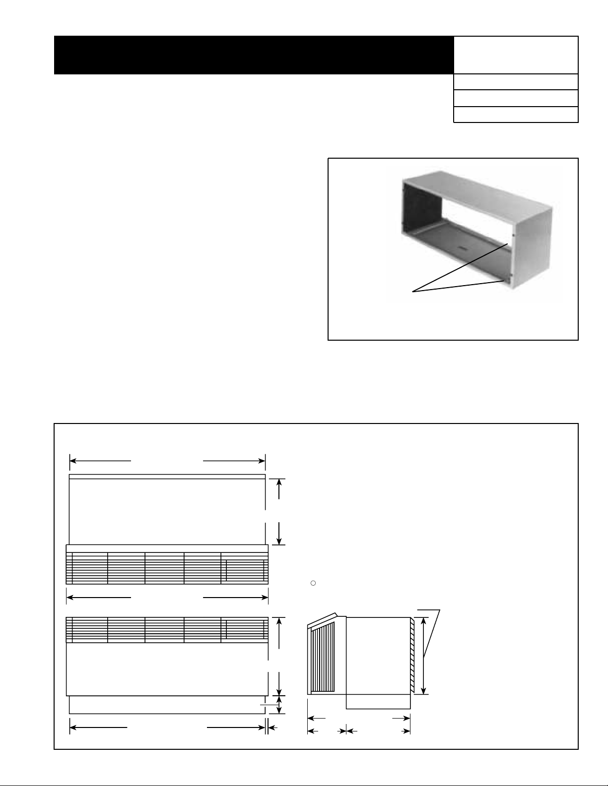
Figure 2. Unit with Subbase
42"
(1067 mm)
3
/4"
13
(349 mm)
43"
(1092 mm)
Figure 1. Wall Sleeve
➤
➤
Tinnerman
Clips
Note: Wall sleeve shown with optional insulation installed.
4. Caulk indoor/outdoor perimeter of cabinet/wall sleeve with
resilient caulk such as silicone.
5. Finish any uncompleted electrical and/or plumbing
connections.
Notes:
*Subbase Side Dimension:
**Subbase Height Dimension:
➀ Unit pictured with subbase installed. Subbase is optional on 208V and 230V units .
➁ Subbase extends to front edge of unit when furnished with hydronic heat.
➂ Opening needs to be 16
4
Electric: 4
Hydronic: 0" to 13
Electric: 3" to 4" (76mm to 102mm) with 0" to 1" (0mm to 25m) leveling
Hydronic: 8" (203mm) with
Subbase is standard on all 265V units and units with hydronic heat. Hydronic
subbase is flush with the front of the cabinet. Electric subbase is flush with w all
sleeve.
frame.
Subbase side channels are adiustable from 4
3
/8" to 133/4" (111mm to 349mm)
3
/4" (0mm to 349mm)
screw
5
16" (406 mm)
1
/4" (6mm) to 11/4" (32mm) leveling bolts
/8" x 425/8" (422mm x 1083mm) when using a louver
3
/8" to 133/4" (111mm to 349mm).
1
/2"
41
(1054 mm)
1
/2"
16
(419 mm)
**
©1999 AAF–McQuay Incorporated IM 420-1 / Page 1 (Rev. 5/99)
➀
1
/4"
8
(210 mm)
22" (559 mm)
*
Page 2
Wall sleeve installation — frame and brick
A heavy-gauge, corrosion resistant cabinet/wall sleeve is
provided for each unit. The cabinet/wall sleeve is either shipped
in a separate carton, shipped in a multipack of 15 or in a single
carton with the heating/cooling chassis.
The standard cabinet/wall sleeve is designed to be easily
installed in a variety of wall constructions. Note: The center of grav-
1
ity is 10
sleeve must be inserted into the wall at least 10
support must be employed. Support can be from a factory supplied
subbase or from other field supplied materials. Recommended
installation procedures are described below.
1.
2. If the unit is to be supplied with a subbase, install subbase
3. lf the optional drain kit is to be employed (heat pump only),
4. Place a thin pad of soft mortar on the bottom of the opening
5. Level cabinet/w all sleev e in both directions and secure by an-
6. Caulk the cabinet/wall sleev e to the wall opening on both the
/4" (260mm) from the rear face of the wall sleeve. The wall
1
/4" (260mm) or other
Clean the opening of all debris that may interfere with installation.
before installing cabinet/wall sleeve (see IM 419 or IM 420).
see IM 430-2.
and slide in the cabinet/wall sleev e. Be sure to recess the wall
sleeve enough to accommodate outside louver. This recess
3
is
/8" (9.5mm) for stamped louvers and 11/4" (32mm) for architectural louvers. Louver should be flush to exterior surface
with complete. Note: The wall sleeve is not intended to replace the lintel.
choring with appropriate fasteners. A
5
/16" (8mm) hole is provided on each side, 2" (51 mm) down from the top and 2"
(51mm) in from the rear of the cabinet/wall sleev e . Additional
holes may be required to firmly secure the cabinet/wall sleeve.
Caution:
sleeve.
Do not drill holes in the base of the cabinet/wall
Where a subbase is used, secure wall sleeve to sub-
base with clips provided.
inside and outside perimeter. Be careful not to plug the weep
holes. Caulking should be resilient, nonhardening type such
as silicone.
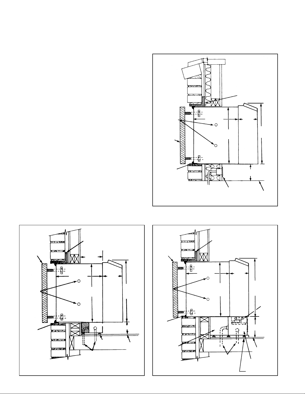
Figure 3. Frame and brick with cord connection
STEEL LINTEL (BY
OTHERS)
MOUNTING
SCREWS BY
INSTALLER
OUTDOOR
LOUVER
CAULK
PERIMETER
133/4"
(349mm)
WALL SLEEVE
16"
(406mm)
WALL
RECEPTACLE
BY OTHERS
81/4"
(209mm)
ROOM
CABINET
3" MIN.
(76mm)
17"
(432mm)
FINISHED
FLOOR OR
CARPET
Figure 4. Frame and brick with standard electrical subbase
STEEL LINTEL
BY OTHERS
OUTSIDE
LOUVER
133/4"
(349mm)
MOUNTING
HOLES BY
INSTALLER
CAULK
PERIMETER
BOTH
INDOORS &
OUTDOORS
BEFORE
INSTALLING
LOUVER
WALL SLEEVE
Note: Standard subbase is available in 3" or 4" (76 mm or 102 mm) height.
Leveling legs provide adjustment of 1" (25 mm).
IM 420-1 / Page 2 (Rev.5/99)
43/8"
(111mm)
81/4"
(209mm)
16"
(406mm)
ROOM
CABINET
SUBBASE
LEVELING LEG
POWER SUPPLY CONNECT
(ALTERNATE ENTRY)
17"
(432mm)
SEE NOTE
FINISHED
FLOOR OR
TOP OF
CARPET
Figure 5. Frame and brick with hydronic subbase
STEEL LINTEL
(BY OTHERS)
OUTDOOR
LOUVER
MOUNTING
SCREWS BY
INSTALLER
CAULK
PERIMETER
BOTH
INDOORS &
OUTDOORS
BEFORE
INSTALLING
LOUVER
SUBBASE
CHANNEL
SIDE
133/4"
(349mm)
WALL
SLEEVE
16"
(406mm)
ALTERNATE
ELECTRICAL
CONNECTIONS
81/4"
(209mm)
ROOM
CABINET
17"
(432mm)
81/4"
(209mm)
HYDRONIC
SUBBASE
HYDRONIC
HEATING
COIL
FINISHED
FLOOR OR
CARPET
Page 3

Wall slee ve installation–
panel wall construction
For panel wall and thin wall construction, it is recommended that
a louver frame be used.
Panel wall and thin w all construction varies only slightly from
frame and brick construction. Note: The center of gravity is 10"
(260mm) from the rear face of the wall sleeve. The wall sleeve
must be inserted into the wall at least 10" (260mm) or other
support must be employed. Suppor t can be from a factory
supplied subbase or from other field supplied materials.
Installation for this application is as follows:
1. Clean the opening of all debris that may interfere with
installation.
2. If the unit is to be supplied with a subbase, install subbase
before installing cabinet/wall sleeve (see IM 419 or IM 420).
3. If the optional drain kit is to be employed, see IM 430-3.
4. Be sure the cabinet/wall sleeve is mechanically attached to
the wall and caulked to assure a proper seat. It is
recommended that the louver frame be used for this purpose.
5. Recess the wall sleeve so that the louver is flush with the
exterior of the building.
6. Level cabinet/wall sleeve in both directions and secure by
anchoring with appropriate fasteners or drill additional holes
as required to secure firmly . Caution:
base of the cabinet/wall sleeve.
secure wall sleeve to subbase with clips provided.
7. Caulk the cabinet/wall sleev e to the w all opening on both the
inside and outside perimeter. Be careful not to plug the weep
holes. Caulking should be resilient, nonhardening type such
as silicone.
Do not drill holes in the
Where a subbase is used,
Certified Drawing
Figure 6. Panel wall construction with cord connection
LOUVER
FRAME
17"
(432mm)
3"MIN. (76mm)
FLOOR
RECEPTACLES
BY OTHERS
81/4"
(209mm)
ROOM
CABINET
CONDUIT
(349mm)
16"
(406mm)
SUPPORTS FIELD
133/4"
WALL
SLEEVE
PERIMETER
OUTDOORS
MINIMUM 2
SUPPLIED
OUTDOOR
LOUVER
CAULK
BOTH
INDOORS &
Figure 7. Panel wall construction with
standard electrical subbase
LOUVER
FRAME
OUTSIDE
81/4"
(209mm)
17"
(432mm)
SEE NOTE
ROOM
CABINET
POWER SUPPLY
(ALTERNATE ENTRY)
(406mm)
CONDUIT
Note: Standard subbase is available in 3" or 4" (76 mm or 102 mm) height.
Leveling legs provide adjustment of 1" (25 mm).
16"
ELECTRICAL
133/4"
(349mm)
WALL SLEEVE
SUBBASE
GASKET &
PERIMETER
SUBBASE SIDE
CHANNEL
LOUVER
CAULK
Figure 8. Panel wall installation with hydronic subbase
LOUVER
FRAME
16"
(406mm)
SUBBASE
CHANNEL
133/4"
(349mm)
WALL
SLEEVE
SIDE
PERIMETER
BOTH INDOORS
& OUTDOORS
IM 420-1 / Page 3 (Rev. 5/99)
81/4"
(209mm)
17"
(432mm)
81/4"
(209mm)
ROOM
CABINET
HYDRONIC
HEATING
COIL
POWER SUPPLY CONDUIT
(ALTERNATE ENTRY)
LEVELING LEGS
W/1" ADJUSTMENT
OUTDOOR
LOUVER
CAULK
Page 4

Wall sleeve installation– thick wall construction
Installation of cabinet/wall sleeves f or thick w alls requires special
consideration. Table 1 should be used to determine the
maximum wall thickness allowed for the standard cabinet/wall
sleeve. For thicker walls, cabinet/wall sleeve extensions are
available from your representative.
Wall sleeve installation in thick walls is similar to frame and
brick installation. Install as follows:
1. Clean the opening of all debris that may interfere with
installation.
2. If the unit is to be supplied with a subbase, install subbase
before installing cabinet/wall sleeve (see IM 419 or IM 420).
3. If the optional drain kit is to be employed (heat pump only),
see IM 430-3.
4. If wall thickness exceeds dimensions shown in Table 1, a
cabinet/wall sleeve extension must be used. Once the
extension is attached to the cabinet/wall sleeve, place a thin
pad of soft mortar on the bottom of the opening and slide in
the wall sleev e/extension assembly. Be sure to recess the wall
sleeve enough to accommodate outside louver. This recess
3
/8" (9.5mm) for stamped louvers and 11/4" (32mm) for ar-
is
chitectural louvers. Louver should be flush to exterior surface
when completed. Note: The wall sleeve is not intended to replace the lintel.
5. Level cabinet/wall sleeve in both directions and secure by
anchoring with appropriate fasteners or drill additional holes
as required to secure firmly . Caution:
base of the cabinet/wall sleeve.
secure wall sleeve to subbase with clips provided.
6. Caulk the cabinet/wall sleev e to the w all opening on both the
inside and outside perimeter. Be careful not to plug the weep
holes. Caulking should be resilient, nonhardening type such
as silicone.
Figure 10. Thick wall construction with
standard electrical subbase
SEE
TABLE 1
CAULK
PERIMETER
Do not drill holes in the
Where a subbase is used,
STEEL
LINTEL
(BY OTHERS)
43/8"MIN.
(111mm)
MAXIMUM WALL THICKNESS
LOUVER
TYPE
Stamped
Architectural
NO
SUBBASE
14"(356mm)
7
14
/8"(378mm)
STANDARD
SUBBASE
91/2"(241mm)
3
10
/8"(264mm)
HYDRONIC
SUBBASE
131/8"(333mm)
14"(356mm)
Figure 9. Thick wall construction with cord connection
CAULK
PERIMETER
OUTDOOR
LOUVER
MOUNTING
SCREWS BY
INSTALLER
SEE
TABLE 1
13
(349mm)
WALL
SLEEVE
WALL
SLEEVE
EXTENSION
3
/4"
16"
(406mm)
1
/8"(3mm)
MIN.
LINTEL (BY
OTHERS)
81/4"
(209mm)
ROOM
CABINET
3"MIN.(76mm)
STEEL
17"
(432mm)
WALL
RECEPTACLE
BY OTHERS
Figure 11. Thick wall installation with hydronic subbase
SEE T ABLE 1
CAULK
PERIMETER
STEEL
LINTEL BY
OTHERS
1" (25mm)
FLOOR
SEE
NOTE
MOUNTING
SCREWS BY
INSTALLER
OUTDOOR
LOUVER
Note: ➀ Standard subbase is available in 3" or 4" (76 mm or 102 mm) height.
Leveling legs provide adjustment of 1" (25 mm).
2
WALL
SLEEVE
EXTENSION
3
13
/4"
(349mm)
(406mm)
ELECTRICAL
SUBBASE
16"
81/4"
(209mm)
ROOM
CABINET
SEE NOTE 1
17"
(432mm)
FLOOR
➁ Wall sleeve extension is available in various depths and supplied as
required.
AAF–McQuay Incorporated
4900 Technology Park Boulevard, Auburn, New York 13021-9030 USA (315) 253-2771
Printed on recycled paper containing at least 10% post-consumer recycled material.
IM 420-1 / Page 4 (Rev. 5/99)
MOUNTING
SCREWS BY
INSTALLER
OUTDOOR
LOUVER
WALL SLEEVE
133/4"
(349mm)
WALL
SLEEVE
EXTENSION
16"
(406mm)
81/4"
(209mm)
ROOM
CABINET
HYDRONIC
HEATING
COIL
17"
(432mm)
8
(209mm)
HYDRONIC
SUBBASE
1
/4"
FLOOR
 Loading...