

Page 1

Page 2
GENERAL
The Model ST air cooled condensing units are complete assemblies, factory tested and shipped with a
Refrigerant 22 holding charge. They have been designed to operate in conjunction with remote direct
expansion evaporator(s) and are available for operation
on three phase power supplies (see the published
catalog data for power ratings available). All units have
115 volt control circuits with provision for connection
of a remote mounted 24 volt thermostat. Additional
information on the units is covered on the pages
following.
McQUAY
RESPONSIBILITIES
The Model ST condensing units when applied within
the performance and application limits specified on the
sales and installation data will provide safe and
dependable service.
Details on the Model ST product warranty are included
in the information envelope packed with the unit.
RECEIVING EQUIPMENT
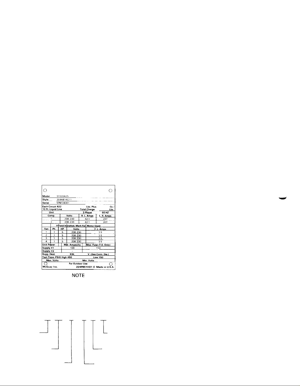
1. CHECK EQUIPMENT before removing it from the
delivery vehicle. The unit nameplate (shown below)
indicates the unit model number, power characteristics, serial number, etc. Be sure to check the
nameplate data against the shipping papers and pay
particular attention to the unit model number (size)
and power characteristics.
2.3.INSPECT the unit while it is still on the delivery
vehicle, make a note of any damage on the delivery
receipt. Be sure to carefully check for hidden
damage. If damage is found, have it checked and
noted by the representative of the transportation
company before accepting or removing the unit
from the vehicle.
NOTE
All equipment furnished by McQuay is
shipped F.O.B. the factory and all claims
for handling and shipping damage are the
responsibility of the consignee.
If an item is missing from the shipment notify your
nearest McQuay Sales office.
RIGGING - The STO08, 010, 013, and 015 should
be lifted by the skid, the ST020, 025, and 030 from
the lifting holes at the base corners. When lifting
use a spreader bar to prevent damage. If the unit is
to be skidded, be sure an adequate number of
rollers are used and be careful when moving the
unit not to drop it. Under no circumstances should
the unit be dragged with or without the skid.
NOTE
Unit mounting legs are shipped in a separate carton and are located in the compressor compartment. Before setting the unit at
its final location, attach the support legs at
each corner with the bolts provided.
5/8”
anchor holes are provided in the legs for
securing the unit to its base.
When requesting information about this
unit please forward the unit model number,
style and serial numbers with your inquiry.
UNIT MODEL NUMBER INTERPRETATION
ST 020 A
PRODUCT
FAMILY
NOMINAL
CAPACITY-TONS
CONDENSING MEDIUM
A = AIR
J
2 s 00
SPECIAL
MODIFICATIONS
UNIT POWER
CHARACTERISTICS
DESIGN MODIFICATION
CLEARANCES
The unit has been designed to permit slab or roof
mounting and care must be taken to provide adequate
clearance for air flow in and out of the unit.
TOP CLEARANCE - The unit has a draw through air
circuit with vertical air discharge from the top of the
unit. It is important that the areas above and below are
clear of any obstructions that could impede or divert
the air flow and cause recirculation back to the air
inlet.
SIDE CLEARANCE - A minimum clearance of 36
inches is required with the exception of the compres-
sor access end of the unit, where 42 inches is
recommended.
VIBRATION ISOLATION
Internal
isolation of the fan motors generally make it unneces-
sary to provide additional vribration isolation for the
unit. However, additional isolation could be required
depending on the installation location and building
construction.
Wherever possible locate the unit away from or over
occupied areas and provide adequate piping isolation.
Be
where it passes through walls, roof or floors.
spring
mounting of the compressor and
careful
not to allow piping to touch the structure
2
Page 3
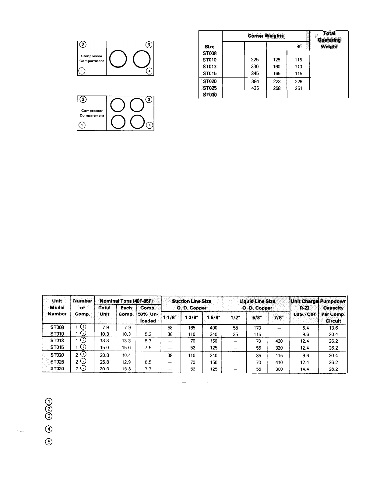
TABLE 1
ST008,010,013
ST020,025,030
m]
AND 015
REFRIGERANT PIPING
Piping between the condensing unit and the cooling
coil must be designed and installed to minimize
pressure drop, prevent liquid refrigerant carryover to
the compressor and to assure a continuous return of
compressor oil from the system. Piping sketches and
tables are not intended to provide information on all of
the possible arrangements. For example, when dual
circuit evaporators are used with an unloading com-
UNIT WEIGHT
Unit
Size
ST008
STDlO
ST013
ST015
ST020
ST025
-4
ST630 453
1
180
190
145
150
394
421
Gorn*r
1
2 f
I
210
465 277 270
aide.
I
-
POUNDS
3
I
115
0
4’
110
W&&t
I
Tti
615
645
745
775
1230
1365
1465
pressor, two liquid line solenoid valves may be used to
reduce coil capacity with compressor unloading. Note
especially that dual circuit evaporators should not be
piped with common liquid and suction lines to more
than one compressor. Separate evaporators, evaporator circuits and piping must be run for each compressor.
TABLE 2
SUCTION AND LIQUID LINE SIZES FOR EACH COMPRESSOR
MAXIMUM EQUIVALENT FEET OF COPPER TUBING
-
NOTES
Equivalent line lengths shown in above table are suitable for unit operating
condenser entering air temperature of 95F. When design conditions vary the table values should be rechecked.
0
Compressors used in the ST008 and 020 have no capacity reduction.
@
The compressors used in the
@
When refrigerant required to charge a circuit exceeds the pump down capacity of that circuit the use of a separate refrigerant storage
receiver will be required. The pump down capacity is based on the condenser 80% full at
@
Wherever vertical rise occurs in the piping, the minimum tonnage for oil entrainment should be checked and where necessary double
suction risers should be utilized. See Table 4, page 4.
@
Total equivalent feet for a given piping layout must include the equivalent length of straight pipe for fittings, valves and specialties added
to the total run of straight pipe.
ST010,
013, 015,025 and 030 have a single 50% capacity reduction step.
-
conditions
between 40 and 45F saturated suction temperature and
8OF.
3
Page 4
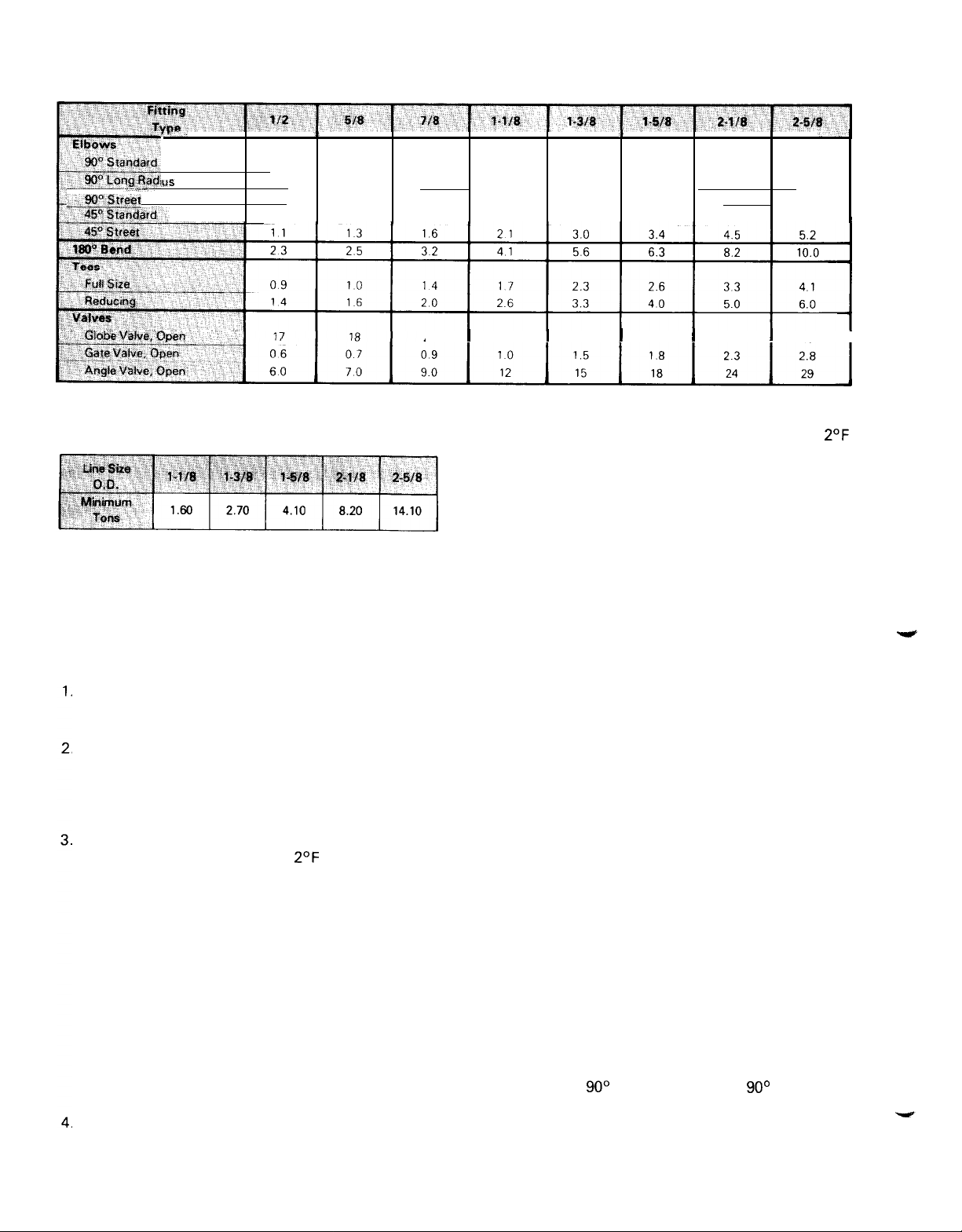
TABLE 3
EQUIVALENT FEET OF STRAIGHT TUBING FOR COPPER
16 20
10 14
25 32
08 09
22
ws
_.qQtq":?&qt
14
0.9
23
07
TABLE 4
Minimum Tonnage (R-22)
To Carry Oil Up Suction Riser
NOTE. When compressor minimum tonnage is less than shown in the
above table for a given line size, double suction risers will be
required.
To preclude potential problems that could be traced to
piping,
standard accepted piping practices as de-
scribed below and in the ASHRAE handbooks are
recommended.
Piping recommendations include:
The use of type K or L clean copper tubing. All
joints should be thoroughly cleaned and brazed
with high temperature solder.
Piping sizes should be based on temperature/
pressure limitations as recommended in the following paragraphs. Under no circumstances should
pipe size be based upon the coil or condensing unit
piping connection size.
Suction line piping pressure drop should not exceed
the pressure equivalent of
2’F
per 100 feet of
equivalent pipe length. After the suction line size
has been determined, the vertical suction risers
should be checked to verify that oil will be carried
up the riser and back to the compressor. The
suction
line(s)
should be pitched in the direction of
refrigerant flow and adequately supported. Lines
should be free draining and fully insulated between
the evaporator(s) and the compressor. Table 2,
page 3 shows piping information for units operating
at suction temperatures between 40 and 45 and a
condenser entering air temperature of 95. If operating conditions are expected to vary substantially
from these operating levels, the pipe sizing should
be rechecked.
Vertical suction risers should be checked using
Table 4, page 4 to determine the minimum tonnage
required to carry oil up suction risers of various
sizes.
I
26 33
17
41
13
I 29
2.3
5.6
1.7
I
38
FlTTlNGS AND
I
4.0
2.6
63
2.1
I
43
VALVES
5.0 6.0
3.3
82
2.6 3.2
55
I
I
69
5. The liquid line should be sized for a pressure drop
not to exceed the pressure equivalent of
saturated temperature. The liquid
line(s)
on all units
must include a liquid solenoid valve wired into the
circuit as shown on the applicable unit wiring
diagrams. The valve must be connected as follows:
1.
On model ST008, 010, 013, and 015 the solenoid
must be wired between terminals “P and N.”
2. Models ST020, 025, and 030 will require two sole
noid
valves, one in each liquid line. Make wiring
connections between terminals “P and N” for
circuit number 1 and “PI and N1" for circuit
number 2.
The unit control circuit for all compressors has been
designed to include a one time pump down cycle.
The use of a liquid line solenoid is required for
proper unit operation. In addition, a filter/drier
should be located between the liquid line service
valve and the solenoid valve and a combination
moisture indicator/sight glass should be located in
the liquid line ahead of the expansion valve.
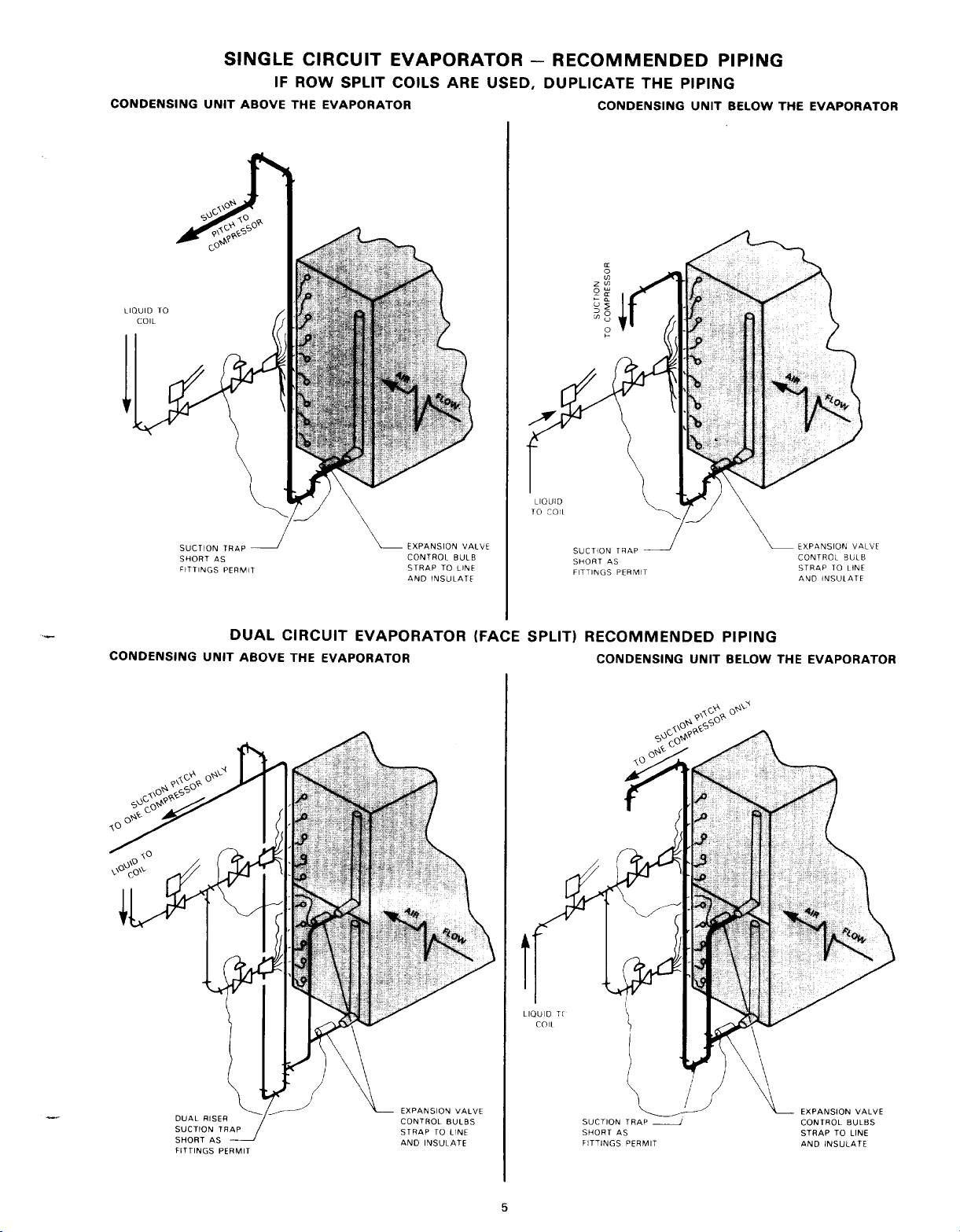
6. Suggested piping arrangements are shown on page
5.
All
multiple compressor units require a separate
refrigerant circuit for each compressor.
7. If Dual Suction Risers are Used:
A.
The combined cross sectional areas of the two
risers must be capable of maintaining adequate
refrigerant velocity for oil return at full unit
tonnage.
B.
The extra risers should be of a smaller diameter
than the main riser. The extra riser must
include its own trap at the bottom and should
enter the main suction header at twelve o’clock.
C.
The trap serving the extra riser must be as short
as fittings permit. A “U” fitting or the combination of a
90’
standard
ell
and a
90’
street
recommended.
D.
The suction line leaving the coil should also
include a trap if the expansion valve control bulb
is to be on the horizontal section leaving the coil
outlet. See the piping sketches on page 5.
4
4.1
10.0
ell
I
2’F
is
Page 5
Page 6

LEAK TESTING
All model ST condensing units are evacuated leak
tested and provided with a holding charge of R-22 at
the factory. Check the unit when it arrives at the job
site for damage or leaks in the refrigerant circuit. If the
refrigerant charge has been lost, locate and repair the
leak at the same time the connecting system is
checked. When you are ready to leak test, charge
enough R-22 into the system to raise the pressure to
about 30 psig; then add dry nitrogen and bring the
pressure up to a maximum of 150 psig. The system can
now be checked for leaks. Before attempting to repair
any leaks that may have been found, be sure to relieve
the test pressure from the system.
IMPORTANT CAUTION
Always use a pressure regulating valve on
the nitrogen drum and be sure to
nect the drum from the system after the
maximum of 150 psig test pressure is
reached. Under no circumstances should
you exceed the maximum leak test pressure
of 150 psig. DO NOT USE OXYGEN TO
BUILD UP PRESSURE, A SERIOUS EXPLOSION COULD RESULT.
discon-
EVACUATION
After all leaks have been repaired the system can be
evacuated, proceed as follows:
Connect a good quality manometer or gauge
(capable of measuring one millimeter of vacuum)
into the system and locate it as far away as possible
from the vacuum pump.
The triple evacuation method is recommended.
Evacuate the system to 29” vacuum, then add enough
R-22 to break the vacuum and bring the system up to
10 psig pressure. Repeat this evacuation ‘two more
times and on the third evacuation break the vacuum by
feeding R-22 into the system through the gauge port
on the condenser liquid shut off valve. With the
refrigerant cylinder up ended, it should be possible to
install close to 75% of the required charge into the
system in this manner without starting the com-
pressor. Do not start the compressor until the
following checks have been made.
PRELIMINARY CHECKS BEFORE
STARTING COMPRESSOR(S)
1.
With the unit disconnect switch off, check to be
sure that the starter contacts meet evenly and that
all operating starter parts move freely. Check that
the time delay fuses
are of the proper size.
2.
Open all refrigerant
charge, and liquid).
3.
With the thermostat
room thermostat below the design temperature.
Check that the air handling unit fans are rotating in
the proper direction.
in the unit disconnect switch
service valves (suction, dis-
in the “off” position, set the
Close the disconnect switch which energizes the
4.
crankcase heaters. These heaters must be ener-
gized 8 hours before attempting to start the
compressor(s).
Check that line voltage is within
5.
compressor nameplate voltage rating.
+ 10 percent of the
CHARGING
With the cylinder still up ended, charge as much
1.
refrigerant as possible into the system. When the
system will no longer accept refrigerant in this
manner, disconnect the drum from the liquid valve
and reconnect it to the gauge port on the suction
service valve.
Check the compressor oil level. If the oil level is
2.
over the top of the glass, be prepared when the
compressor starts to shut it down if sounds of liquid
pumping are evident.
Recheck that the suction, liquid and discharge line
3.
shut off valves are open. Close the unit disconnect
switch and set the room thermostat to call for
cooling.
With the compressor operating, continue to allow
4.
refrigerant to enter until the estimated charge has
been weighed in and/or the sight glass clears. At
this point, check the liquid line temperature leaving
the condenser, it should indicate 10 to 12 degrees
of subcooling.
Another method of checking the refrigerant charge
after the initial 75% has been added to the unit
would be to block the condenser coil until the head
pressure is built up to about 300 psig. Continue to
add refrigerant until the sight glass clears and 10 to
12 degrees subcooling is obtained.
Regardless of the method used to charge the unit,
refer to the charging and operating curves applicable to the unit involved and check operating
pressures against the curve values.
After about one hour of operation, check the compressor amperage being drawn. It should not exceed the
Full Load Amperes listed on the unit nameplate.
Also check that the combination sight glass/moisture
indicator is showing a dry condition. If moisture is
indicated, a refrigerant drier will have to be added into
the system.
TABLE 5
APPROXIMATE OPERATING CHARGE
FOR COMPRESSOR CIRCUIT
NOTE: Approximate charge includes evaporator coil, condensing
unit, liquid line drier and approximately 25 ft. of
liquid line per circuit. Refrigerant charging should be
performed as described under “Charging” on Page 6.
-
R-22, LBS
suction
and
6
Page 7

Page 8

Page 9

Page 10

Page 11

Page 12

Page 13

Page 14

Page 15

TYPICAL SCHEMATIC WIRING FOR MODELS
ST 025 AND
030
FUSE ~
115V.
BUSSMAN
FUSE PRIMARY CON
TRANSFORMER BUSS
4AMP
TYPE
NEC CLASS 2
MDX
COB WkllNG
-
X2 SYS
ONLY.
ON~OFF
FUSE
2.5A
SEE NOTES, PAGE 13
schematic diagram
shown on page 16
BEHIND TERM
HOUSING
BLOCK
TYPE S
UNIT LAYOUT
REFERENCE DRAWING
Xl COMPRESSOR
598C686-SUB
6
OPTIONAL
EQUIPMENT
ACCESSORY ITEMS
LOW AMBIENT FAN SPEED CONTROL - By
adding an accessory fan speed control to the last
operating fan motor on all model ST008 through 015
units, the minimum operating ambient temperature as
shown on Table 6, page 7 can be reduced to
O’F for all
unit operating capacities. This control is a standard
accessory available from McQuay for field installation.
TIME DELAY RELAY - On two compressor units
(models ST020 through
030),
it may be desirable to
prevent simultaneous starting of both compressors on
a call for cooling. An accessory time delay relay is
available for field installation in the unit operating
control circuit. This relay will add a short time delay
and only allow one compressor to start at a time.
SUCTION LINE ACCUMULATOR - Some systems,
depending on line length, solenoid valve leakage, etc.,
may require the use of a suction line accumulator to
prevent damage to the compressor from liquid
carry-
CONTROL CIRCUIT OPERATION
Refer to the schematic diagram shown on page 16. A
single line voltage fused disconnect switch must be
field supplied in the wiring supplying power to the unit.
With the disconnect switch closed, power is supplied
to the primary of the control transformer located on
over when the compressor first starts. A standard
accessory accumulator with a liquid capacity of 31
pounds is available for field installation in the suction
line of each compressor circuit.
PRESSURE GAUGES - Are available in kit form for
field installation.
HOT GAS BYPASS - This accessory option is
available for field installation on units where the
minimum capacity step does not reduce sufficiently to
meet the minimum load requirement. The use of hot
gas bypass is recommended on systems where evaporator air flow is varied or where the load at standard
air flow reduces sufficiently to cause a low suction
pressure condition. The kit contains all parts required
to adapt model ST units to hot gas bypass. It must be
used on systems with side outlet distributors on the
coil or on systems where it is permissible to introduce
hot gas between the expansion valve and evaporator
unit.
line 47, a secondary control voltage of 115 volts is
generated by the transformer.
A second transformer (115 to 24V) is located on line
74. On a call for cooling by either or both of the room
thermostats “1TC” or
relays
“1CR”
and “2CR”
2TC,”
on lines 78 and 80 are energized through the indoor
unit fan coil unit interlock contacts
(5MA).
15
Page 16

Page 17

Assume thermostat contacts
cooling, relay coil “ICR” contacts on lines 56 and 59
will be closed. Closing the
energize the compressor starter holding coil
through the high pressure cutout
switch
pressure cutout
gized, the contacts on lines I, 3 and 5 and auxiliary
contacts
sor number 1 and auxiliary contacts 1MA line 54 provide an interlock circuit parallel to the
on line 56. A second set of
close and energize liquid line solenoid valve “1 LS”.
In addition, the closing of relay “1CR” contacts on line
56 also provides voltage to the
(line 53).
After
actuated contacts
necessary to load the compressor.
When either the first or second stage of the thermostat
calls for cooling the compressor starter auxiliary
contacts
the condenser fan motor
Contactors
through outdoor ambient thermostats
as the outdoor temperature changes. See table 7 on
page 8 for details on the action of the head pressure
control.
To insure that the indoor fan starter is energized,
before the condensing unit can be started, indoor fan
starter auxiliary contacts must be installed in the open
section of the control circuit between terminals Yl-Sl
and
identified on the schedmtic diagram as
5MA2.”
The unit control circuit incorporates a one time
down control. For example, when the second step on
(SWS1),
1CR
Y2-S2
overload contacts
(1
LP). With holding coil
“1MA”
contacts have closed the suction pressure
1MA or
on line 54 close. This starts compres-
“1CC”
2MA
on lines 70 and 72 will energize
“4M”
and
on lines 78 and 80. These contacts are
“1TC”
are calling for
1CR
contacts on line 56 will
“1M”
(1HP),
the system
(1OL
and the low
“1M”
ener-
“1CR”
contacts
1CR
contacts on line 59
“1OL”
overload module
on line 53 can open when
contactors 3M,
“5M”
can also be cycled
4M and 5M.
“1TA
and
“5MA1”
pump-
2TA”
and
the two-stage thermostat is satisfied and opens contacts 2TC on line 80, cooling relay 2CR is de-energized
opening relay contacts on lines 64 and 67. The circuit
on line 65 is maintained by the 2MA starter auxiliary
contacts on line 62. The liquid line solenoid valve on
line 67 is de-energized when the 2CR relay contacts
ahead of it are opened. De-energizing the solenoid
valve cuts off the flow of refrigerant to the number 2
expansion valve. The compressor continues to run because the circuit to compressor starter holding coil 2M
is maintained by the 2MA auxiliary contacts on line 62.
The compressor continues to run and pump refrigerant
from the system until the setting of low pressure
cutout “2LP” on line 65 is reached and the contacts of
this control are opened. When this occurs the compressor starter holding coil 2M is de-energized, opening the starter contacts on lines 7, 9 and 11 and
auxiliary contacts 2MA on line 62. Suction pressure
switch “2LP” is automatic reset and when it does
reset, the compressor will not restart because both
relay contacts 2CR (Line 64) and starter auxiliary
contacts 2MA (Line
sor cannot be restarted until the 2TC thermostat again
calls for cooling and relay coil 2CR is energized again
closing 2CR contacts on lines 64 and 67. A similar
sequence will occur when thermostat contacts
open.
Also built into the compressor control circuit is a timed
off provision to prevent the compressor from restarting
after it has cycled off. A period of 3 to 5 minutes must
elapse before the compressor can restart. This function
is built into all model ST condensing units. On all units
except models ST010 and 020, this time delay is built
into the solid state control, on the ST010 and 020 it
is provided by separate time delay relays
“2TD.”
62)
are both open. The compres-
“1TD”
1TC
and
MAINTENANCE AND SERVICE
CRANKCASE HEATERS - The unit power supply
must be kept on at all times during the operating
season to keep the compressor crankcase heaters
energized. If the power is disconnected the compressor(s) could be damaged.
-
COMPRESSOR LUBRICATION
sealed compressors used in the model ST unit assem-
bly will not require additional lubrication once the
unit has been checked out and placed in operation.
In the event a large quantity of oil is lost as the
result of refrigerant leak, the system may require the
addition of oil.
CONDENSER FAN MOTORS
used on model ST008, 010, 013, 015 and 020 are
supplied with
ings. These motor bearings should be checked annually and lubricated with 20 weight non-detergent
oil.
The model ST025 and 030 units utilize permanently
lubricated ball bearing type motors.
CONDENSER COIL - The condenser coil should be
inspected and cleaned on a regular basis. Accumulation of leaves, paper and surface dirt should be
brushed from the finned surface. Annually the finned
prelubricated
sealed sleeve type bear-
The hermetically
-
The fan motors
surface should be cleaned using a fin cleaner. A dirty
condenser coil can increase unit power consumption
by as much as twenty percent.
INDOOR FAN AND EVAPORATOR COIL
indoor air handling system must be inspected and
serviced on a regular basis. Filters should be clean,
“V” belt tension adjusted and the evaporator coil
surface clean. In addition, the drain pan should be
clear of algea and the condensate should drain freely.
-
SEASONAL SHUTDOWN
need be made for end of season shutdown.
SEASONAL STARTUP
The crankcase heater circuit must be energized at
least eight hours before attempting to start the
compressor.
The air handling
serviced.
The unit condenser coil should be clean and free
of any debris that mav have accumulated during the
shutdown period.
Check and tighten all electrical connections.
Refer to section
Starting,” (page 6).
17
unit(s)
No special provisions
-
should be inspected and
“Preliminary Checks
-
The
before
Page 18

TROUBLE SHOOTING GUIDE
Possible
Cause
FUSE
BLOWN
COMPRESSOR
STARTER
OVERLOAD
RELAY
TRIPPED
LOW
PRESSURE
CUTOUT
TRIPPED
T
HIGH
PRESSURE
CUTOUT
TRIPPED
Possible
Reasons
Motor or Winding
Grounded.
Fuse or Wire
Too Small
Compressor seized
Compressor
Drawing
Excessive
Current
Low Indoor
Refrigerant
Expansion Valve
not Opening
Refrigerant Charge
inoperative
Non-Condensables
in the Condenser
Overcharge
Refrigerant
Airflow
Restricted
Flow
Loss of
Evaporator
Fan
of
Checking
Procedure
Test for grounds, loose
wire connections, starter
contact adjustment
Check Table 9,
Megger motor
Check wiring for size
and/or loose connections
Check whether phase
unbalance exceeds 3%
Reset compressor lockout
Run compressor, check
starting, noises, and
for amperge drawn
Operate condensing unit,
check evaporator coil for
slow even frosting
Check liquid line strainer,
liquid line, suction line
for temperature change.
frost or ice will generally
indicate restriction.
Remove bulb, hold in
hand. Feel distributor
to see if valve opened
Check liquid line
temperature and
sight glass
Verify voltage at motor,
remove belt, spin
motor by hand.
Check air temperature
rise across condenser,
purge condenser,
observe effect on
condensing pressure
Purge refrigerant, check
for reduction in head
pressure
Page 10
Possible
Remedy
Replace wire, tighen connections of if
is grounded, replace it.
Replace as required
Replace compressor
if required
Replace wire if necessary,
tighten
Consult with
power company
Replace compressor
Clean or replace filters,
clean evaporator coil,
increase fan speed, correct
indoor fan rotation
Remove restriction
Adjust or replace
power element.
Leaktest system, repair
leak, evacuate when
necessary, recharge
Replace or repair motor
Evacuate system
Remove refrigerant until
operating pressures are
normal.
compressor
connections.
CONTROL
CIRCUIT
OPEN
MOTOR
TEMPERATURE
SENSOR OPEN
Air Cooled Condenser
Fan(s) Inoperative
Thermostat
Contacts
Open
Protective
Control
Defective
Defective
Starter
Coil
Motor
Temperature
too High
Verify voltage at motor,
check bearings.
Adjust to lowest setting,
check for voltage across
compressor starter
operating coil
Check switch operation
Check voltage at coil. If
burned will generally have
burned odor and dark
appearance
Check motor for failure,
check voltage, check
running current, check
refrigerant charge
Megger Motor
18
Replace motor or repair
defective bearing
If thermostat is defective,
replace
If defective, replace
If defective replace coil
Correct operating
conditions or if motor
is defective, replace.
Page 19

TROUBLE SHOOTING GUIDE
NOISY
COM
PRESSOR
Low Refrigerant
Charge
Low
Air
Deliverv
Compressor
Not
Pumping
Compressor
Running
Unloaded
I
_iquid
refrigerani
flooding back
to compressor
Defective
Compressor
Head
Valves
System Leak
Coil and or Filter Dirty
Fan Speed too Low
Evaporator
Fan
Problem
Head Valves
Broken or
Head Gaskets
Blown
Unloading solenoid
Valve Stuck in
Unloaded Position
Faulty Expansion
Valve or Improper
Suoerheat Settinq
Liquid Refrigerant
Returning to Compressor
Expansion Valve and
Liquid Line Problems
Excess Oil in Svstem
Normal Wear
Check operating pressures Leak test, repair
and liquid line recharge
temperatures
Inspect filters and coil
Check fan speed and duct.Adjust fan speed, if
resistance against design
specifications
Start and stop fan,
observe rotation of
blades.
Check temperatures by
hand. Discharge and
suction lines warm cylinder Replace compressor
hot. Check suction and
discharge pressure
Check unloading solenoid Replace coil or valve
valve for defect
Check super heat
Try to pump system
down. Check how fast
discharge and suction
pressures equalize
Clean or replace filters,
clean coil
restriction is in duct may
require laraer motor
If fan rotation is wrong
correct by fan interchanging motor
connections
Readjust or replace valve
If compressor will not
pump or pressures equalize
too fast, replace
compressor.
OIL
PRESSURE
PR0BLEMS -
Liquid
Refrigerant
Returning to
Compressor
Oil Trapping
Expansion Valve Not
Set Properly, Leaking
Liquid Solenoid Valve
Piping Problem
Check valves Adjust or replace
as necessary
Check piping arrangement
and size. Check for
Check for possible traps.
Modify as necessary
valve(s)
19
 Loading...