

Page 1
Installation Manual IM: 908
Smoke Detector
Group: MPS
Date: January 2008
Supersedes: None
The MQuay smoke detector is designed specifically for applications where standard external
mount detectors cannot be utilized, such as air shafts, plenum spaces, or applications requiring
extremely low, or no air velocity. The detector provides early detection of smoke and
combustion present in the air of a duct supply, return, or both, in commercial, residential, and
industrial applications.
Contents
• Specifications.............................................................................................................. page 2
• Terminal Connections................................................................................................. page 2
• Installation .................................................................................................................. page 2
© 2008 McQuay International
Page 2
Specifications
Table 1: Unit Specifications
Power Requirements
Standby Current 60 Hz Alarm Current
24 V (ac) – 54.4 mA
24 V (dc) – 15 mA
115 V (ac) – 31 mA
230 V (ac) – 18 mA
Alarm Contacts:
Trouble Contact:
Air Velocity
Ambient Temperature:
Humidity:
Material:
Dimensions:
Max. Weight:
Radioactive element:
Mounting:
24 V (ac) – 139 mA
24 V (dc) – 48 mA
115 V (ac) – 34 mA
230 V (ac) – 20 mA
Unit Ratings
1 set form “C” rated at 10 A @ 115 V
(ac) resistive
1 form “A” rated at 2 A
1 set form “B” rated at 10 A @ 115 V
(ac) resistive
0 to 3000 ft/min.
32° to 140°F (0° to 60°C)
0% to 85% RH non-condensing/non-
freezing
White platic base/housing and detector
6" diameter, 4" H overall/2.6" front to
back
1.0 lb
Americum 241, 0.9 micro curie
Standard 4" square back box
Terminal Connections
Prior to connecting input power to the duct unit, determine the
correct input voltage/current availability and connect to the
correct terminals.
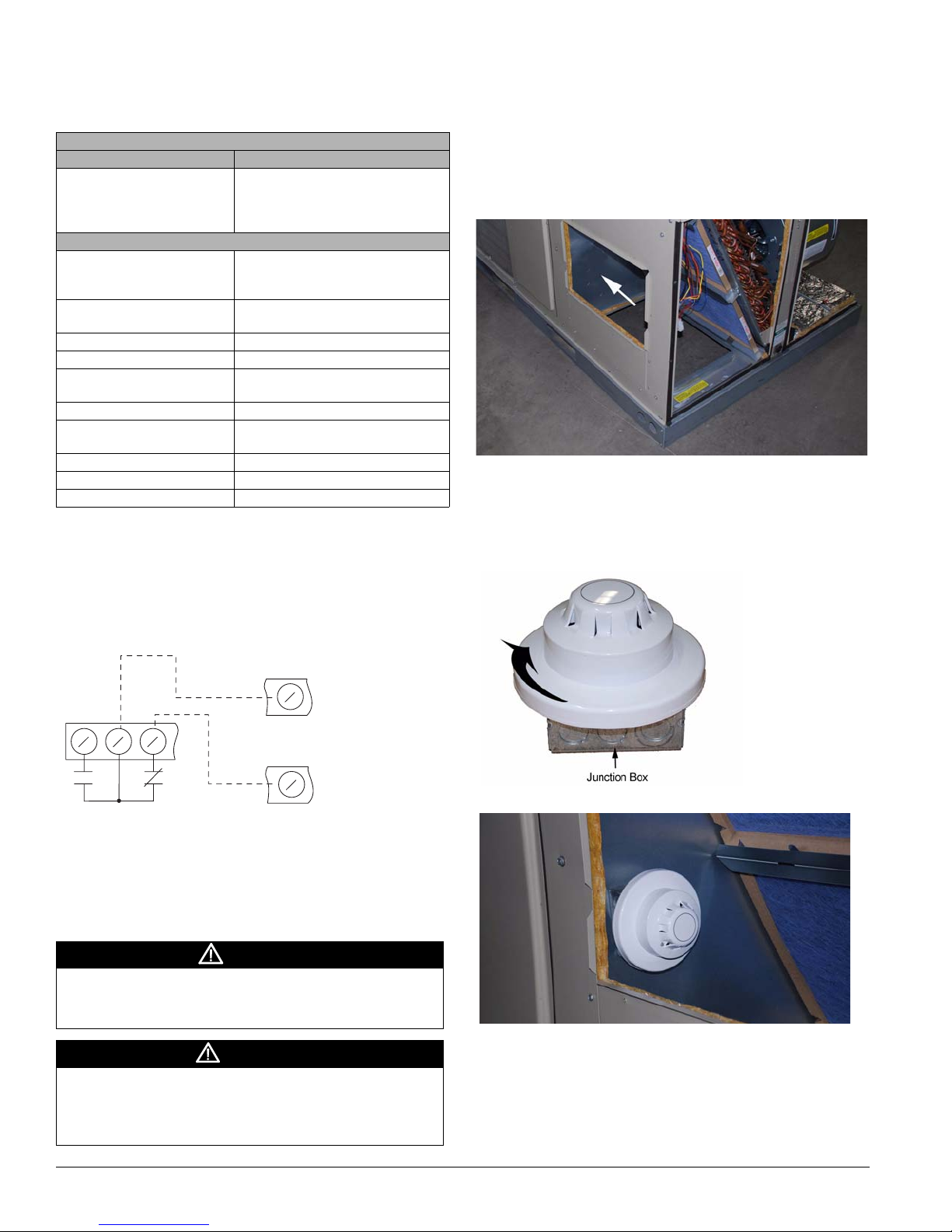
1 The smoke detector can be mounted in the duct or in the
return air section of the unit. If installing inside the unit,
locate an area where there is a uniform, non-turbulent
airflow of between 500 and 3000 ft/min (example shown in
Figure 2). Other possible installation locations are inside
the economizer and inside the curb.
Figure 2. Non-Turbulant Airflow Area for Mounting
2 Mount a 4 x 4 junction box in this non-turbulant airflow
area. Twist the smoke detector onto the screws on the top
of the junction box (Figure 3) to form a complete installed
unit (Figure 4).
Figure 3. Mounting the Smoke Detector to Junction Box
Figure 1. Dry Contact Outputs Alarm
MPS TERMINAL
R
ALM - N.O.
ALM - COM
8910
15 A @ 124 V (ac)
10 A @ 277 V (ac)
7 A @ 30 V (dc)
1/4 HP @ 125/250 V (ac) (N.C.)
1/3 HP @ 125/250 V (ac) (N.O.)
ALM - N.C.
°
T-STAT TERMINAL
R
°
Installation
DANGER
Moving machinery and electrical power hazards. Will
cause severe personal injury or death.
Disconnect and lock off all power before servicing equipment.
CAUTION
Sharp edges on sheet metal and fasteners can cause
personal injury. This equipment must be installed, operated,
and serviced only by an experienced installation company and
fully trained personnel.
Figure 4. Junction Box and Smoke Detector Installed
3 Run the wires for the 24 VAC and NC contacts back to the
control panel.
Note: For Maverick units, the wires may be run with the
existing exhaust fan wiring or economizer wiring.
2 McQuay IM 908
 Loading...