

McQuay Skyline OAH 003, Skyline OAC 004, Skyline OAC 003, Skyline OAH 004, Skyline OAH 006 Installation And Maintenance Manual
...Page 1

Installation and Maintenance Manual IM777
Skyline Outdoor Air Handler
Sizes 003 - 055
Group: Applied AIr
Part Number: IM777
Date: April 2003
© 2003 McQuay International
IM777 Page 1
Page 2

Table of Contents
Nomenclature ...................................................................... 2
General Information .................................. .......................... 3
Receiving and Handling .................................................. 3
Unit Storage .....................................................................3
Installation Guidelines ........................................................ 4
Service Clearances .......................................................... 4
Rigging ............................................................................ 4
Curb Mounting and Leveling .......................................... 5
Section Assembly ............................................................5
Access Doors and Panels ................................................. 6
Duct Connections ............................................................ 7
Dampers and Hoods ........................................................ 7
Mounting Actuators ......................................................... 8
Face and Bypass Section Mounting ................................ 8
Piping Vestibules ................................ ............................. 8
Piping and Coils ....................................... ....................... 8
Drain Pan Traps ............................................................. 11
Internal Isolation Assembly Adjustment .......................11
Nomenclature
OAH 003 F D A C
Electrical Installation .....................................................12
Operation Guidelines .........................................................13
Startup Checks ...............................................................13
Fan Wheel Alignment ....................................................14
Fan Operating Limits .....................................................16
Fan Vibration Levels ......................................................17
Service and Maintenance ..................................... ..............18
Periodic Service and Maintenance .................................18
Ball Bearing Lubrication ................................................18
Fan Drive Adjustments ..................................................18
Drive Belt Adjustment ...................................................21
Front Load Filter Option ................................................22
Winterizing Water Coils ................................................23
Coil Maintenance ...........................................................23
Component Removal & Replacement ...........................24
Warranty ............................................................................26
Warranty Return Material Procedure .............................26
Replacement Parts ..........................................................26
Model
OAH = Outdoor air handler
OAC = Outdoor component
Nominal Unit Size
(nominal square foot of coil)
003, 004, 006, 008, 010, 012,
014, 017, 021, 025, 030, 035, 045, 055
Vintage of McQuay Air Handling Unit
Unit Cross Section
C = Standard unit cross section
M = Custom size cross section
Motor Location
A = Motor along side of fan housing
D = Motor downstream of belt drive plenum fan
F = Motor on inline fan
G = Motor downstream of direct drive plenum fan
T = Motor behind twin housed fans
Unit T y pe/Co il Positi on
B = Blow-thru cooling coil location
D = Draw-thru cooling coil location
H = Heating only
V = Vent only
Page 2 IM777
Page 3

General Information
The system design and installation must follow accepted
industry practice, such as described in the ASHRAE Handbook, the National Electric Code, and other applicable standards. The installation of this equipment must be in
accordance with regulations of authorities having jurisdiction and all applicable codes. It is the responsibility of
the installer to determine and follow the applicable codes.
Installation and maintenance must be performed by qualified personnel familiar with applicable codes and regulations, and experienced with this type of equipment. Sheet
metal parts, self-tapping screws, clips, and such items
inherently have sharp edges, and it is necessary that the
installer exercise caution.
CAUTION
SHARP EDGES AND COIL SURFACES
are a potential injury hazard. Avoid contact with them.
ATTENTION
Les bords tranchants et les surfaces des bobines sont un
risque de blessure. Ne les touchez pas.
Receiving and Handling
1. Carefully check items against the bills of lading to verify
all crates and cartons have been received. Carefully
inspect all units for shipping damage when received.
Report damage immediately and file a claim for damage
with the carrier.
2. Skyline air handler units are constructed of heavy-gauge
galvanized steel and are thoroughly inspected before leaving the factory. Care must be taken during installati on to
prevent damage to units.
3. Take special care when handling the blower section. All
fans are dynamically balanced before leaving the factory.
Rough handling can cause misalignment or a damaged
bearings or shaft. Carefully inspect fans and shaft before
unit installation to verify this has not happened.
4. If necessary, screws, bolts, etc., for assembly of sections
are supplied in a bag attached to each section. All necessary gasketing is applied in the factory for section to section mounting. Units require caulk sealant between
sections.
Unit Storage
Store unit on a level surface. If air handling units are to be
stored for any period of time, it is important to periodically
rotate the fan wheel. The fan wheel should be periodically
rotated to prevent permanent distortion of drive components. In
addition, grease may settle in the lower part of the bearing,
which may lead to oxidation on the upper portion of the bearing
surface. It is also important to keep the fan bearings lubricated.
IM777 Page 3
Page 4
Installation Guidelines
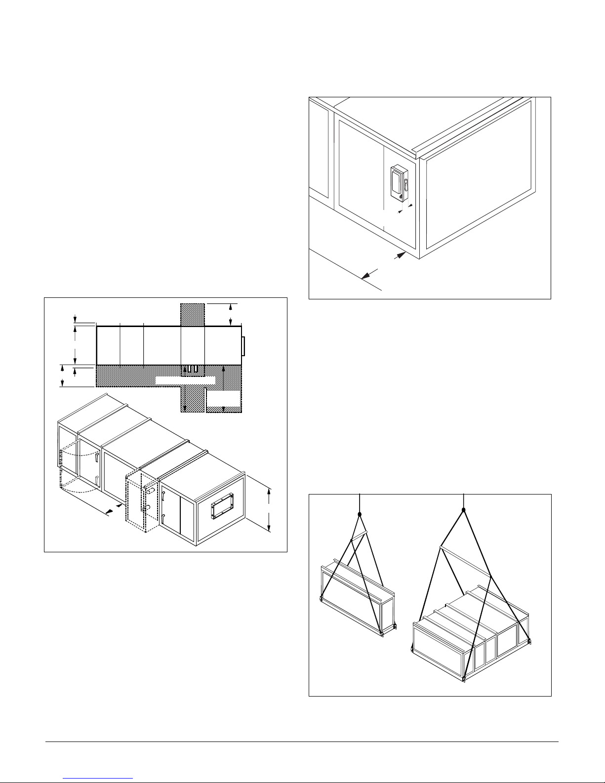
Service Clearances
In addition to providing adequate space around the unit for
piping coils and drains, access is always required on at least
one side of the unit to allow for regular service and maintenance. Filter replacement, drain pan inspection and cleaning,
fan bearing lubrication and belt adjustment are examples of
routine maintenance that must be performed. Sufficient space
must also be provided on the side of the unit for shaft
removal and coil removal if necessary . Space at least equal to
the length of the coil is required for coil removal. Refer to the
"Coil data" section in Catalog 570 for information about coil
sizes. See Figure 1 for servicing space requirements.
At least 54" of clearance must be maintained in front of electrical power devices. Electrical power devices that are
mounted on the side of the unit are typically up to 12" deep.
See Figure 2.
Figure 1. Servicing space requirements
4.00" Lifting Bracket
Width
30.00"
4.00"
Width of coil section
30.00"
Width of
fan section
Figure 2. Service clearance for electrical power devices
1 2 "
5 4 "
Rigging
Skyline air handlers ship completely assembled, or in sections. The unit must be rigged as it ships from the factory.
Do not rig units after assembly. Unit s ar e p rovide d wit h a
factory installed base rail and can be lifted using the 2" diameter lifting holes located in the corners of each shipping section.
To prevent damage to the unit cabinetry, use spreader bars.
Spreader bars must be in position to stop cables from rubbing the frame or panels. Before hoisting into position, test
lift for stability and balance. Avoid twisting or uneven lifting of the unit.
Figure 3. Unit and section rigging
3
0
.
0
0
"
Page 4 IM777
Height
Page 5

Curb Mounting and Leveling
Do not place a Skyline unit over an open curb unless it is
equipped with a curb-ready base. Installation instructions for
mounting units on a roof curb are provided in IM770. For a
copy , contact your local McQuay Representative or visit
www.mcquay.com. Make provisions under the unit to divert
any moisture from entering the building below.
For units without roof curb mounting, place the equipment on a flat and level surface. Where surface irregularities exist, shim the base of the unit at one or more points
along the length of the rails to prevent distortion or sagging. Uneven or distorted sections will cause misfit or
binding of the doors and panels and improper draining of
drain pans. See Figure 4.
Figure 5. Apply sealant to mating faces
1 / 4 " d i a m e t e r
b e a d c e n t e r e d
i n f a c e o f
c l e a r a n c e
U s e S p l i c e
J o i n t a s a
g u i d e
Figure 4. Leveling the unit
Shim sections until
they are straight
and level
Shim to prevent
distortion if width
is over 108"
Section Assembly
If the unit is shipped in more than one shipping section, rig
each section into position separately. Shipping sections are
provided with a connection splice joint attached on the leaving air side of the shipping section that seals against the
frame channel on the entering-air side of the adjoining section. The splice joint is insulated, and provides an air-tight
seal between two sections once they are assembled together.
The Splice Joint must be aligned to seat into the mating gasket to provide an air seal. If the Splice Joint was bent during
shipping or rigging, verify it is restored to its origin al position. Figure 6 on page 5.
2. Pull sections together to fasten. Use straps and a ratchet to
help pull the sections together securely. Apply sealant to
any gaps that may admit moisture.
3a.Fasten base rails together first using the 3/8"-16 by 5"
bolts found in the splice kit provided with the unit
See Figure 6. To fasten 2 shipping sections together, 4
bolts are needed (two on each side of the unit). The bolts
are run from one base rail into the other and fastened with
a nut. Complete each section bottom and top before
attaching additional sections.
Figure 6. Fasten bottom of section
Use the following procedure to assemble shipping sections:
1. Caulk all assembly joints of the unit. The mating faces of
the cabinet must have at least a 1/4 inch diameter bead of
sealant applied before the sections are joined. Use the
splice joint as a guide for application of the sealant. See
Figure 5.
IM777 Page 5
3 / 8 x 1 " B o l t a n d N u t
3b.If desired, shipping sections for non curb-ready units can
be fastened together internally. Internal fastening is
achieved by running field provided #10 sheet metal
screws or drill screws (4" long maximum) through the
interior frame channel of one unit into the splice joint of
the neighboring section.
Page 6

Figure 7. Internal fastening
flanges. Bend the ends of the splice cap down to secure in
place. Assemble the small splice plate at the top rail to
secure the sections together at the top. Use 5/16" bolts.
See Figure 9.
Figure 9. Splice cap & splice plate
S l i d e S p l i c e C a p o n
a n d b e n d e n d s d o w n
Splice Collar
must be aligned
to seal to gasket.
A
View A
3c.Units with curb-ready ba ses and vesti bules must be han-
dled so that the lifting bracket can be removed after the
unit is placed on the curbing. Remove the lifting bracket
that projects inward over the curbing. Save the self tapping screws. When the adjacent section is placed in position, use self tapping screw to secure the bases together.
Figure 8. Remove vestibule lifting bracket
5 / 1 6 - 1 8 B o l t
5 / 1 6 - 1 8 N u t
S p l i c e
P l a t e
Access Doors and Panels
For routine maintenance, access is normally obtained through
access doors or by removing side panels. Removing all flat
head fasteners along the sides of a panel will allow it to be
removed.
Fan and filter sections are always provided with a service
door on one side of the unit. If requested on order, doors can
be provided on both sides of the unit. Optional service doors
are available for most section types, and are provided based
on customer request.
NOTE: Opening fan section doors requires the use of a 1/2"
socket wrench. This satisfies ANSI standards and other codes
that require the "use of tools" to access compartments containing moving parts or electrical wiring. See Figure 10.
1. Remove padlock if one is present.
CAUTION: DO NOT attempt to rotate the cup.
Damage to the unit will occur.
R e m o v a b l e
L i f t i n g B r a c k e t
4. Check that the sealant is compressed between the mating
channels when the unit sections are joined. Touch up any
places where gaps are noted. After sections are seated
tightly together, slip the splice cap over the top panel
Page 6 IM777
2. Insert 1/2" socket into cup and rotate 1/4 turn clockwise as
shown in Figure 10. If the cup and handle are on the left
side of the door, rotate 1/4 turn counter-clockwise.
3. Rotate door handle 1/4 turn clockwise, then 1/4 turn
counter-clockwise to release any internal pressure or vacuum and open the door. If the cup and handle are on the
left side of the door, rotate door handle 1/4 turn counterclockwise, then 1/4 turn clockwise.
4. To prevent air leakage, tighten the door panels by adjusting the jam nuts.
Page 7
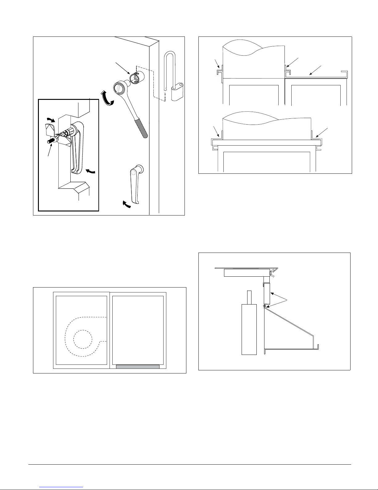
Figure 10. Opening fan section door
Figure 12. Flashing over top panels and sides of units
Do Not Rotate Cup
Jam
Nuts
View from inside door
OPEN
Duct Connections
Flexible connectors should be used on the outlet and inlet
duct connections of all units. Do not position down flow fans
over air ducts that are routed down into the building. A discharge plenum is recommended when bottom connections
are necessary. See Figure 11.
F l a s h i n g
D u c t
F l a s h i n g
D u c t
F l a s h i n g
U n i t t o p
p a n e l
F l a s h i n g
Dampers and Hoods
Side dampers may be provided in the mixing box and economizer sections of units. When dampers are provided, a
removable panel is located above the weather hood to provide access to the damper drive shaft. Other access may be
available depending on the specific construction of the unit.
See Figure 13.
Figure 13. Filler panel over the weather hood
Figure 11. Discharge plenum
D i s c h a r g e
P l e n u m
If the unit has a top mixing box or econo mi zer damper, or a
top duct connection, flashing mu st be field fabricated and
installed to divert moisture from the connection. The flashing
must lap over the standing seams of the top panels. The
flashing must also lap over the side edges of th e unit. See
Figure 12.
Remove screws
and panel to access
damper control shaft.
Hood
When units are ordered with exhaust hoods and intake hoods
adjacent to each other, a field supplied barrier is recommended to prevent re-circulation of exhaust air into the
intake openings. See Figure 14.
IM777 Page 7
Page 8

Figure 14. Field installed barrier between hoods
I n t a k e
B a r r i e r
E x h a u s t
Mounting Actuators
The installing contractor is responsible for the mounting of all
field installed actuators. No provisions are made for the location of these actuators due to the number of options and
arrangements available and the variety of specific applications.
Ty pically, actu ators are mounted insi de the cabinet . Provide
proper support for the actuator to avoid excessive stress in the
cabinet, linkage, or damper shafts.
Piping Vestibules
The openings for routing the field piping must be cut as
required in the field for units that include a piping vestibule.
Carefully seal passages cut through the panels to prevent air
leakage. A single metal thickness pan is provided in the
bottom of the curb mounted vestibule. The pan can be
removed if necessary. If holes are cut into the pan for a piping
passage, seal the holes to prevent moisture leakage.
See Figure 15.
Figure 15. Seal holes for piping - curb mounted units
Seal Holes
Cut for Piping
Note: Damper blades are at full flow when open to 70
degrees. Do not open blades further than 70 degrees.
Fresh air and return air dampers can be linked together and
driven from the same actuator if the dampers are the same
size. If the dampers are different sizes, they must be driven
by separate actuators and controlled appropriately. Exhaust
dampers are always driven by a separate actuator.
A typical rotary electric actuator can handle up to 40 sq. ft. of
damper. For pneumatic actuators, allow 5 in-lb. per square
foot of damper area.
Face and Bypass Section Mounting
Internal and external face and bypass sections are mounted
together using the instructions for horizontal components and
do not require additional instruction. Skyline air handlers are
provided with a bypass duct that is integral to the unit construction and requires no field assembly.
Face and bypass dampers may or may not be linked together.
When dampers are placed before a single bank of coils, they
are always linked together and require a single actuator.
When dampers are bypassing a stacked or staggered coil, the
dampers are not linked and will require multiple actuators.
Face and bypass dampers have a torque requirement of 10 inlbs. per square foot of damper face area.
For units with standard base rails, the vestibule is open to the
coil section so all holes must be sealed to prevent air leakage.
Figure 16. Seal holes for piping - standard base rail units
Seal Holes
Cut for Piping
Piping and Coils
Follow applicable piping design, sizing, and installation
information presented in ASHRAE Handbooks in the design
and installation of piping. Observe all local codes and industry standards. Undue stress should not be applied at the connection to coil headers. Pipework should be supported
independently of the coils.
Page 8 IM777
Page 9

Water Cooling Coils
Note:It is recommended that Glycol be used in water coils for
outdoor air handlers. Power failures and other mechanical issues can expose coil s to freezing temperatures.
1. Water supply, water return, drain, and vent connections
extend through the end panel of the coil section. All connections are labeled on the end panel.
2. Water supply and water return connections are typically
male N.P.T. iron pipe.
3. When installing couplings, do not apply undue stress to
the connection extending through unit panel. Use a
backup pipe wrench to avoid breaking the weld
between coil connection and header.
4. Follow recommendations of the control manufacturer
regarding types, sizing, and installation of controls.
Direct Expansion Coils
1. The coil distributor and suction connection extend
through the end panel of the coil section.
2. Check nozzle in distributor for proper tonnage.
3. When a thermostatic expansion valve is supplied with the
unit, it will be located outside the unit and connected
directly to the distributor (except on units with piping vestibules). Do not apply heat to the body of the expansion valve.
4. The thermostatic expansion valve must be of the external
equalizer tube type. Connect the 1/4-inch diameter external equalizer tube provided on the coil to connection on
expansion valve.
5. Use care when piping up the system to see that all joints
are tight and all lines are dry and free of foreign material. For typical refrigerant piping, see condensing unit
product manual.
Steam coils (refer to Figure 17 on page 10)
Note: Steam traps should not be placed outdoors.
1. All steam coils in units are pitched toward return
connection.
2. Steam supply and steam return connections are typically
male N.P.T. iron pipe and are labeled o n the en d panel of
coil section. Connections extend through coil section end
panel.
3. When installing couplings, do not apply undue stress to
the connection extending through unit panel. Use a
backup pipe wrench to avoid breaking the weld
between coil connection and header.
4. Support piping independently of coils and provide adequate piping flexibility. Stresses resulting from expansion
of closely coupled piping can cause serious damage.
5. Do not reduce pipe size at the coil return connection.
Carry return connection size through the dirt pocket, making the reduction at the branch leading to the trap.
6. Install vacuum breakers on all applications to prevent
retaining condensate in the coil. Generally, the vacuum
breaker is to be connected between the coil inlet and the
return main, the vacuum breaker should be open to the
atmosphere, and the trap design should allow venting of
large quantities of air.
7. Do not drip supply mains through the coil.
8. Do not attempt to lift condensate when using modulating
or on/off control.
9. Size traps in accordance with manufacturers' recommendations. Be certain that the required pressure differential
will always be available. Do not under-size.
10.Float and thermostatic or bucket traps are recommended
for low pressure steam. On high pressure steam, bucket
traps are normally recommended. Thermostatic traps
should be used only for air venting.
11.Bucket traps are recommended for use with on/off
control only.
12.Locate traps at least 12 inches below the coil return
connection.
13.Multiple coil installation.
a. Each coil or group of coils that is individually con-
trolled must be individually trapped.
b. Coils in series: Separate traps are required for each
coil, or bank of coils, in series.
c. Coils in parallel: A single trap may generally be used
but an individual trap for each coil is preferred.
d. Do not attempt to lift condensate when using modu lat-
ing or on/off control.
14.With coils arranged for series airflow a separate control is
required on each bank or coil in the direction of airflow.
15.Modulating steam valves are not recommended on high
pressure systems.
16.Modulating valves must be sized properly. Do not
under-size.
17.Freezing conditions (entering air temperatures below 35°F).
a. 5JA, 8JA, 5RA and 8RA coils are strongly recommended.
b. 5 psi steam must be supplied to coils at all times.
c. Modulating valves are not recommended. Control
should be provided by face and bypass dampers.
d. Consideration should be given to the use of two or three
coils in series with two position steam control valves on
that coil or coils which will be handling 35°F or colder
air. The desired degree of control can be at tain ed wit h a
modulating valve on the downstream coil.
e. Thoroughly mix fresh air and return air before it enters
the coil. Also, temperature control elements must be
properly located to obtain true air mixture temperatures.
f. As additional protection against freeze-up, the trap
should be installed sufficiently below coil to provide
an adequate hydrostatic head to provide removal of
condensate during an interruption in the steam pressure. Estimate three feet for each 1 psi of trap differential required.
g. On startup, admit steam to coil ten minutes before
admitting outdoor air.
h. Close fresh air dampers if steam supply pressure falls
below minimum specified.
IM777 Page 9
Page 10

Figure 17. Piping arrangements
Steam main
Float and
thermostatic trap
Vacuum breaker
1/2" check valve
1/4" petcock
for continuous
air venting
1"
min.
12" min.
5GA or 8GA coils. Note the addition of
a vacuum breaker to permit the coil to
drain during shutdown.
Vacuum breaker
1/2" check valve
Chec k Valve Strainer Gate V alve
High pressure (over 25 psi)
Steam main
Return main
1/4" petcock
for continuous
High pressure
float or bucket
trap
Return main
air venting
High pressure
bucket trap
5TA, 8TA, or 5HA coils. Condensate
is lifted to overhead return main
Low pressure (to 25 psi)
Vacuum breaker
1/2" check valve
1" min.
Steam main
Control valve
modulating
two position
12" min.
Full size of
return conn.
Steam main
12" min.
5J, 5G, 8J or 8G coils.
Steam main
Vacuum breaker
1/2" check valve
Return main
5RA, 8RA, or 5SA coils. Installed
Return main
Vacuum breaker
1/2" check valve
12" min.
Full size of
return conn.
Steam main
12" min.
5JA or 8JA coil. Installed in series.
Note that each coil must have a
separate control valve and trap.
Return main
Vacuum breaker
1/2" check valve
Return main
5RA, 8RA, or 5SA coils. Banked two
high, individual trapping of each coil as
shown is preferred.
Page 10 IM777
Page 11

Water heating coils
1. W ater supply and water return connections extend through
the end panel of the coil section. All connections are
labeled on the end panel.
2. Water supply and water return connections are male
N.P.T. iron pipe.
3. When installing couplings, do not apply undue stress to
the connection extending through unit panel. Use a
backup pipe wrench to avoid breaking the weld between
coil connection and header.
4. Follow recommendations of the control manufacturer
regarding types, sizes, and installation of controls.
Figure 19. Extend drain fitting for door clearance
C l e a r a n c e
5. Hot water coils are not recommended for use with entering air below 40°F.
6. If fresh air and return air are to be heated by a hot water
coil, care should be used in the design of the system to
provide thorough mixing before air enters the coil.
7. For preparation of coils for winter operation, see “Winter-
izing Water Coils” on page 23.
Drain Pan Traps
Drain lines and traps should be run full size from the drain
pan connection. Drain pans should have traps to permit the
condensate from the coils to drain freely. On both blowthrough and draw-through units, the trap depth and the distance between the trap outlet and the drain pan outlet should
be twice the static pressure in the drain pan section under
normal operation for the trap to remain sealed. See Figure 18.
Figure 18. Allow adequate distance between tra p o utlet
and drain pan
P r e s s u r e ( P )
a t t h e d r a i n p a n
2 P
2 P
D r a i n
Internal Isolation Assembly
Adjustment
On units with internally isolated fan and motor assemblies,
the assemblies have been secured for shipment with a tiedown at each point of isolation.
Before operating the unit:
Remove the shipping brackets and tie-down bolts and discard. The shipping brackets located on the opposite drive
side of the unit are difficult to access from the drive side of
the unit. Either remove them before the unit is assembled,
or remove the panel on the opposite drive side to gain
access. See Figure 20.
The spring isolators under the four corners of the fan and
motor assembly have been factory adjusted while the fan was
not running. See Table 1. With the unit operating at normal
cfm and static pressure, the isolators should all be at the same
height opening. If adjustments are required, loosen the 1/2"
capscrew on top of the isolator and turn the adjusting bolt to
lower or raise the fan and motor base. Retighten the capscrew
when adjustments are completed.
Note: The door panels on some applications have a close
clearance over the drain pipes. Extend the drain fitting with a
coupling if necessary for door clearance. See Figure 19.
Note: Outdoor drain traps should be made of a material that
can withstand freezing temperatures.
Note: Drain traps that dry out can allow cold air to seep into
the equipment.
IM777 Page 11
Table 1: Factory spring mount adjustments
SPRING MOUNT ADJUSTMENT AT REST
Fan Discharge
Position
1 3.75 3.75 4.25
2 4.25 3.75 4.25
3 4.25 3.75 4.25
4 3.75 3.75 4.25
Top or Bottom Horz. HDownblast
H
Upblast H
Page 12

Figure 20. Removing shipping brackets
S h i p p i n g h o l d d o w n
r e m o v e a n d d i s c a r d
S h i p p i n g b r a c k e t
r e m o v e a n d d i s c a r d
( T y p i c a l 4 p l a c e s )
( T y p i c a l 4 p l a c e s )
S e e d e t a i l " A "
S p r i n g h e i g h t
a d j u s t m e n t
s c r e w
Electrical Installation
1. Electrical service to the fan must correspond to the rated
voltage on the motor nameplate and be in conformance
with the National Electric Code and local restrictions.
2. The fan section metal frame must be connected to the
building electrical ground.
3. A door electrical interlock is not provided as standard.
4. Thermal motor protection is external to the unit.
Electrical conduit entrances for units should be located above
the bottom of the unit enough to clear components inside, but
MUST be located below the bottom of the fan motor junction
box. See Figure 21.
Figure 21. Electrical conduit location
D i m " H "
P O S 3
P O S 4
S p r i n g h e i g h t
a d j u s t m e n t s c r e w
S h i p p i n g
b r a c k e t
M o t o r
F a n
F a n i s o l a t o r p o s i t i o n n u m b e r s
P O S 2
A i r f l o w
P O S 1
S h i p p i n g h o l d
d o w n s c r e w
Fan Motor
Junction Box
Conduit Entrance
(typical)
NOTICE
The base section of each cabinet has a drip pan
installed below every panel that drains to the outside
frame trough. Any holes cut through the bottom of
the unit must also penetrate the drip pan. If holes
are cut in the drip pan, they must be sealed to
prevent moisture leakage.
Page 12 IM777
Page 13

Operation Guidelines
Startup Checks
When performing startup and service, thorough safety
precautions must always be taken. These functions must
be performed by trained, experienced personnel.
WARNING
ROTATING FAN
Can cause severe injury or death. Before servicing fans,
lockout and tag out power.
ATTENTION
Risques de dommages dans le moteur du ventilateur
électrique. Si Ia température de l'air a proximité du
ventilateurest élevée, le moteurdu ventilateur électrique
peut chauffer et brûler. Sur les transmetteurs d'air à
circulation transversale ou les transmetteurs dont le
ventilateur est en aval de l'unité de chauffage, régler la
température de l'air sortant de l'unité de chauffage à
40°C (104°F).
AVERTISSEMENT
PIÈCES MOBILES DANGEREUSES.
Avant de réparer ou entretenir les ventilateurs, coupez
l'alimentation èlectrique de cet appareil et bloquez le
commutateur à OFF.
WARNING
FIRE/ELECTRIC SHOCK HAZARD.
Can cause property damage, personal injury or death.
Fan power supply must be wired and motor frame
grounded in accordance with local electric codes.
AVERTISSEMENT
Risques d´incendie et d' électrocution pouvant causer
des dommages matériels, des blessures et même la
mort. L'alimentation électrique du moteur du ventilateur
de même que la mise à la terre du chàssis du moteur
doivent être faits conformément aux codes
d'installations électriques en vigueur.
WARNING
FAN MOTOR REQUIRES
OVERLOAD PROTECTION.
Failure to provide motor overload protection can result
in fire, property damage, electric shock, personal injury
or death. Connect motor to an overload protective
device rated in compliance with local electric codes.
AVERTISSEMENT
Risques d´incendie et d' électrocution pouvant causer
des dommages matériels, des blessures et même la
mort. Connecter au moteur du ventilateur électrique un
dispositif de protection contre les surcharges conforme
aux codes d'installations électriques en vigueur.
CAUTION
DO NOT OVERHEAT FAN MOTOR
High air temperatures in the fan section can cause the fan
motor to burnout. On draw-through air handlers or air
handlers with the fan section down the air stream from the
heating section, the discharge air temperature of the
heating section must not exceed 104°F (40°C).
Before starting up the unit
Before entering fan section, make sure that fan electrical power
source is disconnected and locked in the "OFF" position.
1. Check that the unit is completely and properly installed
with ductwork connected. Check that all construction
debris is removed and filters are clean.
2. Check that all electrical work is complete and properly
terminated. Check that all electrical connections are tight
and that the proper voltage is connected. Phase imbalance
must not exceed 2%.
3. Ball bearings on fan shaft and motor are prelubricated and
do not need grease before startup.
4. Check tightness of setscrews in bearings and fan wheel(s).
If retightening is needed, make certain the fan wheel(s)
are positioned per Table 2 or Table 3 on page 14 and set-
screws are torqued per Table 6 on page 15.
CAUTION: Equipment damage due to loose fasteners
represents improper start-up and equipment abuse.
It is not covered by the warranty.
5. Check alignment of fan and motor sheaves and belt tension. Adjust if necessary. Check tightness of sheave setscrews and/or capscrews. See Figure 28 and Figure 29 on
page 21.
6. Leak test thermal system to verify that connections are tight.
7. Check that condensate drain is trapped.
8. Rotate shaft by hand to be sure it is free.
9. Fan startup: Fan should start and run. Observe the rotation. If the fan is operating backward, reverse two legs of
the 3-phase supply power.
Note: Variable pitch fan drives are usually provided for operation in the mid-speed adjustment range. However, the drives
are usually shipped with the adjustment opened up for minimum fan speed. The drives should be adjusted for the proper
airflow. See “Fan Drive Adjustments” on page 18.
After first 48 hours of operation
1. Disconnect and lock electrical power source. Check tightness of all bearing, wheel, and sheave setscrews (or capscrews). See Table 6
2. Recheck belt tension and adjust if necessary. Belts tensioned sufficiently to slip one to two seconds at startup
will perform satisfactorily, extending life and reducing
vibration. If retensioning is necessary, be certain sheave
alignment is retained.
IM777 Page 13
Page 14

Fan Wheel Alignment
Table 2: Wheel-to-inlet funnel relationship —
airfoil type fan wheels (housed)
Table 3: Wheel-to-inlet funnel relationship —
forward curved type fan wheels (housed)
Equal spacing
B
all around
A
AIRFOIL
Unit Sizes 003-055
Diameter A (inches) A (mm) B (inches) B (mm)
13.22 4.56 116 0.21 5.33
14.56 5.06 129 0.21 5.33
16.18 5.62 143 0.21 5.33
17.69 6.90 175 0.22 5.59
21.56 7.59 193 0.24 6.10
24.00 8.45 215 0.23 5.84
Notes:
1. Dimensional relationship must be held to obtain rated air performance.
2. Dimension A is achieved by loosening setscrews in wheel hub(s), shifting
wheel(s) axially as needed, and retightening setscr ews.
3. Dimension B is obtained by loosening screw and washer fasteners around
periphery of funnel(s), shifting funnel radially as required, and re-torquing
fasteners.
A
CC
Inlet
Funnel
Diameter (Inches) C (inches) C (mm)
9 x 4 0.25 6.35
9 x 7 0.13 3.30
9 x 9 0.25 6.35
10 0.22 5.59
12 0.35 8.89
15 0.44 11.18
18 0.25 6.35
20 (class 1 & 2) 0.73 18.54
22-1/2 (class 1 & 2) 0.59 14.99
24-1/2 (class 1 & 2) 0.56 14.22
Notes:
1. Dimensional relationship must be held to obtain rated air performance.
2. Adjust dimension C by loosening wheel hub setscrews, shifting wheel(s) axially as needed, and retightening setscrews.
Wheel
Inlet
Funnel
FORWARD CURVED
Unit Sizes 003-055
Page 14 IM777
Page 15

Table 4: Wheel-to-inlet funnel relationsh ip - plenum fans Table 5: Wheel-to-inlet funnel relationship - inline fa ns
OVERLAP
OVERLAP
WHEEL — FUNNEL OVERLAP
SIZE OVERLAP
13 .120
15 .190
16.5 .250
18.25 .310
20 .380
22.25 .440
24.5 .500
27 .560
30 .620
33 .750
36.5 .810
40.25 .880
WHEEL — FUNNEL OVERLAP
SIZE OVERLAP
150 .375
165 .438
182 .562
200 .625
222 .688
245 .750
270 .812
300 .875
Table 6: Bearing collar and wheel hub setscrew torque
SETSCREW MINIMUM TORQUE
Diameter (inches) ft. / lbs. kg. / M.
1/4 5.5 .76
1/16 10.5 1.45
3/8 19.0 2.63
7/16 29.0 4.01
1/2 42.0 5.81
5/8 92.0 12.72
IM777 Page 15
Page 16

Fan Operating Limits
)
Do not exceed the operating limits in Table 7. A fan wheel that
is operated beyond the rpm limits shown may suffer permanent
Table 7: Operating limits - housed fans
FAN OPERATING LIMITS
Forward curved — Housed
Diameter 9 x 4 9 x 7 9 x 9 10.62 12.62 15 18 20 22.25 24.50
Maximum RPM Class I N/A 2189 2223 1934 1614 1328 1155 1050 944 858
Maximum RPM Class II 2244 2854 2896 2518 2091 1725 1450 1200 1030 910
Airfoil — Housed
Diameter 13.22 14.56 16.19 19.69 21.56 24.00
Maximum RPM Class I 3000 3000 2300 2000 1700 1500
Maximum RPM Class Il 4335 3918 3457 2858 2547 2255
Figure 22. Torque for FC variable inlet vanes (in. - lb.) Figure 23. Torque for AF variable inlet vanes (in. - lb.)
distortion or fracture. The resulting unbalance may cause
severe unit vibration.
300
250
200
150
100
90
Torque (in.-lb.)
80
70
60
50
350
400
450
500
550
600
650
FC24.50
FC22.25
800
900
700
750
850
Fan Speed (rpm)
1000
FC20.00
FC18.00
FC15.00
1500
FC12.62
2000
4 5 0
4 0 0
3 5 0
3 0 0
2 5 0
2 0 0
1 5 0
1 0 0
9 0
8 0
7 0
T o r q u e ( i n . - l b . )
6 0
5 0
4 0
3 5
3 0
7 5 0
9 0 0
8 0 0
8 5 0
1 0 0 0
A F 2 4 . 0 0
A F 2 1 . 5 6
1 5 0 0
F a n Spe e d (rpm
2 0 0 0
A F 1 9 . 6 9
2 5 0 0
A F 1 6 . 1 9
A F 1 4 . 5 6
3 0 0 0
A F 1 3 . 2 2
3 5 0 0
4 0 0 0
Table 8: Operating limits — plenum fans
FAN OPERATING LIMITS
Diameter 13.5 15 16.5 18.25 20 22.25 24.5 27 30 33 36.5 40.25
Maximum RPM Class I 2895 2589 2376 2256 2077 1875 1691 1479 1328 1209 1073 972
Maximum RPM Class II 3786 3384 3100 2959 2703 2413 2199 1928 1730 1579 1401 1264
Maximum RPM Class III 4000 4000 3887 3735 3409 3065 2780 2423 2182 1984 1756 1598
4 5 0 0
Page 16 IM777
Page 17

Figure 24. Torque requirements at 100% WOV for SWSI plenum fa ns with NESTED inlet vane
5000
4000
3000
2000
1000
Torque (lb./in.)
900
800
Torque (in.-lb.)
700
600
500
400
300
200
100
600
400
300
200
700
500
Fan Speed (rpm)
0
0
6
2
4
5
0
9
4
5
4
4
2
0
4
5
6
3
0
3
3
300
270
45
2
800
900
1000
2000
1500
3000
Table 9: Operating limits — inline fans, twin fans
FAN OPERATING LIMITS
Inline Fans
Diameter 150 165 182 200 222 245 270 300
Maximum RPM Class I 2727 2488 2236 2041 1835 1665 1476 1330
Maximum RPM Class II 3409 3111 2796 2551 2294 2082 1846 1662
Twin Fans
Diameter 9.5 10.62 12.62 15 18.12 20
Maximum RPM 2400 2000 1600 1400 1200 1000
Maximum HP 10 15 15 30 40 40
Fan Vibration Levels
Each unit as shipped has been trim-balanced to operate
smoothly. If excessive vibration occurs after installation, use
the accepted industry guidelines for field balancing fans. See
Table 10.
Table 10: Vibration levels
FAN SPEED (RPM) VIBRATION
800 or less 5 mils maximum displacement
801 or greater 0.20 in/sec. maximum velocity
Note:Excessive vibration from any cause contributes to premature fan and
motor bearing failure. Overall vibration levels should be monitored every six
months of operation. An increase in levels is an indication of potential trouble.
Vibration causes
1. Wheel imbalance.
a. Dirt or debris on wheel blades.
IM777 Page 17
b. Loose setscrews in wheel hub or bearing-to-shaft.
c. Wheel distorted from overspeed.
2. Bent shaft.
3. Drive faulty.
a. Variable pitch sheaves - Axial and radial runout of
flanges; uneven groove spacing; out of balance. Also
similar faults in driven sheave.
b. Bad V-belts; lumpy, or mismatched; belt tension too
tight or too loose.
4. Bad bearings, loose bearing hold-down bolts.
5. Motor imbalance.
6. Fan section not supported evenly on foundation.
Page 18

Service and Maintenance
Periodic Service and Maintenance
1. Check all moving parts for wear every six months.
2. Check bearing collar, sheave, and wheel hub setscrews,
sheave capscrews, and bearing hold-down bolts for tightness every six months.
Ball Bearing Lubrication
1. Motor bearings - All ball bearings are prelubricated and
do not require addition of grease at time of installation.
However, periodic cleaning out and renewal of grease is
necessary . Please note that extreme care must be exercised
to prevent foreign matter from entering the bearing. It is
also important to avoid over-greasing. Only a high grade,
clean mineral grease having the following characteristics
should be used.
a. Melting point preferably over 302°F (150°C), freedom
from separation of oil and soap under operating and
storage conditions; and freedom from abrasive matter,
acid, alkali and moisture.
b. Specific greasing instructions are located on a label
attached to the fan section door.
2. Fan shaft bearings - All ball bearings are prelubricated
and do not require addition of grease at time of installation. However, periodic renewal of grease is necessary.
Bearings are accessible through access door in fan section. Grease fittings are located in front of door opening
on drive end of blower section. Apply grease slowly until
a very slight bleeding of grease from the seals is noted.
Tie hinged door(s) open. Do not over-lubricate. W ipe of f
any excess grease to prevent overheating.
The lubrication interval varies with the period of operation and temperature of the ambient air. Follow instructions listed below:
Bearing Operating Temp Range
to 130°F
(54°C)
Cont. Operation: 6 months 4 months 2 months
12-Hr. Day Operation: 12 months 12 months 6 months
Table 11: Lubricants recommended for
fan shaft ball bearings
MANUFACTURER PRODUCT NAME
Texaco Lubricants Company Premium RB -30 to 300 -34 to 149
Keystone Ind. Lubricants 81EP-2 0 to 250 -18 to 121
Mobil Oil Corporation Mobilith SCH100 -40 to 350 -40 to 177
Chevron U.S.A. Inc. SRI-2 -20 to 325 -29 to 163
Exxon Company, U.S.A. Ronex MP -40 to 300 -40 to 149
Shell Oil Company Alvania No. 2 -20 to 240 -29 to 116
Note:Temperature ranges over 225°F are shown for lubricants only. High
temperature applications are not suitable for standard air handler components.
to 150°F
(66°C)
over 150°F
(66°C)
TEMP. RANGE
°F °C
Fan Drive Adjustments
WARNING
ROTATING FAN
Can cause severe injury or death. Before servicing fans,
lockout and tag out power.
AVERTISSEMENT
PIÈCES MOBILES DANGEREUSES.
Avant de réparer ou entretenir les ventilateurs, coupez
l'alimentation èlectrique de cet appareil et bloquez le
commutateur à OFF.
WARNING
MOVING PARTS
Do not open the hinged access door and screw-fastened
access panels while the unit is operating. Moving parts
and strong suction forces can cause severe personal
injury or death.
BEFORE ENTERING ANY FAN SECTION, MAKE
SURE THE ELECTRICAL POWER SOURCE TO
THE FAN MOTOR IS DISCONNECTED, LOCKED
OUT AND TAGGED OUT.
Do not enter the fan section while the unit is operating
to determine fan speed.
Upon completion of the air balance, it is recommended that
the variable pitched motor sheave be replaced with a properly
sized fixed sheave. Initially, it is best to have a variable
pitched motor sheave for the purpose of air balancing, but
fixed sheaves maintain balancing and alignment more effectively and provide longer belt and bearing life and vibration
free operation.
With the electrical power disconnected, locked and tagged
out, measure the diameter of the V-belt outer surface where it
passes around the sheave (pitch diameter). Calculate fan
speed from the motor nameplate rpm.
Fan rpm = Motor rpm x
"VM" and "VP" Variable Pitch Key Type
Sheaves
Mounting:
1. All sheaves should be mounted on the motor or driving
shaft with the setscrews "A" toward the motor.
2. Verify that both driving and driven sheaves are in alignment and that shafts are parallel.
3. Fit internal key "D" between sheave and shaft, and lock
setscrew "A" securely in place.
Measured Diameter at Motor Sheave
Measured Diameter at Fan Sheave
Page 18 IM777
Page 19

Adjusting:
1. Loosen setscrews "B" and "C" in moving parts of sheave
and pull out external key "E". (This key projects a small
amount to provide a grip for removing.)
2. Adjust sheave pitch diameter for desired speed by opening
moving parts by half or full turns from closed position. Do
not open more than five full turns for "A" belts or six
full turns for "B" belts.
3. Replace external key "E" and securely tighten setscrews
"B" over key and setscrews "C" into keyway in fixed half
of the sheave.
4. Put on belts and adjust belt tension. Do not force belts
over grooves (see “Drive Belt Adjustment” on page 21).
5. Future adjustments should be made by loosening the belt
tension and increasing or decreasing the pitch diameter of
the sheave by half or full turns as required. Readjust belt
tension before starting drive.
6. Two-groove sheaves must have both halves adjusted by
the same number of turns from closed position to provide
the same pitch diameter.
c. Remove key "F". Note: This key projects a small
amount to provide a grip for removing.
d. Rotate the flange counterclockwise until it disengages
the threads on the sheave barrel.
4. V erify that the driving and driven sheaves are in alignment
and the shafts are parallel. When aligning two-groove
sheaves, allow room between the sheave and motor to get
to capscrews "E".
5. Insert key "C" between the sheave and the shaft and
tighten setscrew "A" securely.
6. If flange and locking ring have been removed, when
replacing them make sure that the inner and outer flanges
are open from the closed position by the same amount as
the other flange. This can be determined by accurately
measuring the top width of the grooves.
7. Insert key "F".
8. Tighten setscrews "D" and capscrews "E".
9. Put on belts and adjust belt tension. Do not force belts
over grooves (see “Drive Belt Adjustment” on page 21).
7. Verify that all keys are in place and that all setscrews are
tight before starting drive. Check setscrews and belt tension after 24 hours service.
Figure 25. "VP" type sheave adjustment
A
S i n g l e G r o o v e
N O T E : D o n o t o p e r a t e s h e a v e w i t h f l a n g e
p r o j e c t i n g b e y o n d t h e h u b e n d .
B
E
A
D
C
T w o G r o o v e
K e y " E " p r o j e c t s
t o p r o v i d e a g r i p
f o r r e m o v i n g
B
E
D
C
"LVP" Variable Speed Sheaves
Mounting:
1. Slide sheave on motor shaft so that the side of the sheave
with setscrew "A" is next to the motor, when setscrew "A"
is in the hub or barrel of the sheave.
2. When setscrew "A" is at an angle in the center flange "B",
it should be mounted away from the motor so that the
outer locking ring and flange can be removed to get to the
setscrew.
3. To remove the flange and locking ring:
a. Loosen setscrews "D".
10.Be sure that all keys are in place and all setscrews and all
capscrews are tight before starting the drive. Check and
retighten all screws and retension belts after approximately 24 hours of service.
Adjusting:
1. Slack off belt tension if belts have been installed.
2. Loosen setscrews "D".
3. Loosen but do not remove capscrews "E".
4. Remove key "F". Note: This key projects a small amount
to provide a grip for removing.
5. Adjust pitch diameter by opening or closing the movable
flanges by half or full turns. Note: Two-groove sheaves
are supplied with both grooves set at the same pitch diameter. Both movable flanges must be moved the same
number of turns to provide the same pitch diameter
for satisfactory operation. Do not open sheaves more
than five turns for "A" belts or six turns for "B" belts.
6. Replace key "F".
7. Tighten setscrews "D" and capscrews "E".
8. If belts have been installed, readjust belt tension. If belts
have not been installed, install them and adjust belt tension. Do not force belts over grooves (see “Drive Belt
Adjustment” on page 21).
9. Verify that all keys are in place and all setscrews and all
capscrews are tight before starting the drive. Check and
retighten all screws and retension belts after approximately 24 hours of operation.
b. Loosen but do not remove capscrews "E".
IM777 Page 19
Page 20

Figure 26. "LVP" type sheave adjustment
"MVP" Variable Speed Sheaves
Mounting:
1. Verify both driving and driven sheaves are in alignment
and the shafts are parallel. The centerline of the driving
sheave must be in line with the centerline of the driven
sheave. See Figure 27.
2. Verify that all setscrews are torqued to the values shown
in Table 12 before starting drive. Check setscrew torque
and belt tension after 24 hours of service.
Adjusting:
1. Adjust motor base forward to release belt tension.
Remove the belts for easier adjustment.
2. Loosen, but do not remove both of the locking setscrews
"A" in the outer locking ring by using a hex key or torque
wrench with a hex bit.
3. Adjust sheave to desired pitch diameter by turning the
outer locking ring. Use a spanner wrench or drift inserted
into the 3 holes that are located 120° apart on the ring.
4. Any pitch diameter can be obtained within the sheave
range. One complete turn of the outer locking ring will
change the pitch diameter 0.233".
5. Do not open sheaves more than the following
• Do not open "B" sheaves more than 4-3/4 turns for the
"A" belts or 6 turns for the "B" belts.
• Do not open "C" sheaves more than 9-1/2 turns.
• Do not open "5V" sheaves more than 6 turns.
• Do not open "8V" sheaves more than 8 turns.
sheave pitch. Do not operate the drive until the locking
screws have been set to the torque specifications.
Table 12: Screw torque values
Nominal
Screw
Size
(Dia-Thds/
In.)
1/4-20NC 150 12.5 100 87 7.3 3/16 50
5/16-11NC 305 25.4 200 165 13.8 1/4 90
3/8-16NC 545 45.4 350 290 24.2 1/4,5/16 150,250
1/2-13NC 1300 108.3 N/A 620 51.7 N/A N/A
5/8-11NC N/A N/A N/A 1225 102.1 N/A N/A
Socket Head
Cap Screws
Seating Torque
(in.-lbs.) (ft.-lbs.) (in.-lbs.) (in.-lbs.) (ft.-lbs.) (in.) (in.-lbs.)
Flat
Head
Socket
Screws
Seating
Torque
Hollow Head Set Screws Only
Lengths equal or
greater than Dia.
Seating
Torque
Seating
Torque
For Lengths (L)
less than Dia.
Length
(L)
Seating
Torque
Figure 27. Sheave adjustment
Must be
parallel
Bearing
Motor
Center lines
must coincide
6. Tighten BOTH locking screws "A" in the outer locking
ring before operating the drive. Use a torque wrench and
tighten to the value shown in Table 12.
7. Replace belts and adjust the motor base to tension the
belts properly. See Figure 29.
8. Do not loosen any screws other than the two locking
screws "A" in the outer locking ring when adjusting the
Page 20 IM777
Must be
parallel
Adjustable
Sheave
Page 21

Figure 28. Sheave adjustment
Adjustable
Center-Flange
Split Taper
Bushing
Fixed
Center-Flange
(2) Locking
Setscrews "A"
Flathead Socket Screws
(Do Not Remove)
Capscrews
(Do Not Remove)
Drive Belt Adjustment
General Rules of Tensioning
1. The ideal tension is the lowest tension at which the belt
will not slip under peak load conditions.
2. Check tension frequently during the first 24-48 hours of
operation.
3. Over tensioning shortens belt and bearing life.
4. Keep belts free from foreign material which may cause
slippage.
5. Make V-drive inspection on a periodic basis. Adjust tension if the belt is slipping. Do not apply belt dressing. This
may damage the belt and cause early failure.
Stationary
End-Flange
Outer
Locking-Ring
Inner Locking-Ring
(3) Holes for
Spanner Wrench
or Drift
Tension Measurement Procedure
1. Measure the belt span. See Figure 29.
2. Place belt tension checker squarely on one belt at the center of the belt span. Apply force to the checker, perpendicular to the belt span, until the belt deflection equals belt
span distance divided by 64. Determine force applied
while in this position.
3. Compare this force to the values in Table 13.
Figure 29. Drive belt adjustment
Deflection =
B
e
Belt Span
64
l
t
S
p
a
n
IM777 Page 21
Page 22

Table 13: Belt deflection force
SHEAVE DIAMETER (INCHES) DEFLECTION FORCE (LBS.)
CROSS SECTION
A, AX
B, BX
5V, 5VX
SMALLEST SHEAVE
DIAMETER RANGE
3.0-3.6
3.8-4.8
5.0-7.0
3.4-4.2
4.4-5.6
5.8-8.6
4.4-6.7
7.1-10.9
11.8-16.0
BELT DEFLECTION FORCE
RPM RANGE
1000-2500 3.7 5.5 4.1 6.1
2501-4000 2.8 4.2 3.4 5.0
1000-2500 4.5 6.8 5.0 7.4
2501-4000 3.8 5.7 4.3 6.4
1000-2500 5.4 8.0 5.7 9.4
2501-4000 4.7 7.0 5.1 7.6
850-2500 4.9 7.2
2501-4000 4.2 6.2
860-2500 5.3 7.9 7.1 10.5
2501-4000 4.5 6.7 7.1 9.1
860-2500 6.3 9.4 8.5 12.6
2501-4000 6.0 8.9 7.3 10.9
500-1749 10.2 15.2
1750-3000 8.8 13.2
3001-4000 5.6 8.5
500-1740 12.7 18.9 14.8 22.1
1741-3000 11.2 16.7 13.7 20.1
500-1740 15.5 23.4 17.1 25.5
1741-3000 14.6 21.8 16.8 25.0
CROSS SECTION A, B, 5V CROSS SECTION AX, BX, 5VX
USED BELT NEW BELT USED BELT NEW BELT
Front Load Filter Option
Front loaded filter options require that the filters be removed
and replaced from inside the unit.
Moving belt and fan can cause severe personal injury or
death. During installation and filter maintenance:
1. Verify that the belt and fan guards on plenum fan units are
always in place.
2. Lock and tag out fans to prevent accidental start up.
3. Do not enter the filter compartment until the fan is completely
stopped.
4. Use approved equipment for reaching filters located above normal reach. Do not step on filter frames or unit components.
5. Floor surfaces must be dry and free of oil or grease.
AVERTISSEMENT
Pendant l'installation et où l'entretien des filtres, une courroie en mouvement ou un ventilateur en opération peuvent
causer des blessures graves où même causer la mort.
1. S' assurer que les gardes de courroie et de ventilateur sont tou-
jours en place.
2. Verouiller les démarreurs des ventilateurs et afficher un avis de
mise-en-garde afin de prévenir tout accident ou démarrage.
3. Attendre que le ventilateur soit complètement arrêté avant d'
entrer dans l' unité.
4. Utiliser seulement des équipements approuvé pour joindre les
bancs de filtres; ne pas mettre soit sur les cadres des filtres ou
même sur toutes composantes de l'unité.
5. La surface des planchers doit être sec et libre de toute trace
d'huile et où de graisse.
WARNING
T o remove filters, rotate the wire clips. This will release both
the pre-filter and the final filter. When installing clean filters, check to verify the filters are fully seated in the frame.
See Figure 30.
Figure 30. Frame and filters with holding clips
Final Filter
Filter Frame
Rotate Wire Clips
Prefilter
Page 22 IM777
Page 23

Table 14 shows the typical filter pressure drop for clean filters at
rated air flow and a final pressure drop for front loaded filters.
Table 14: Filter pressure drops
Bag filters - DriPak 2000
Efficiency 45% 65% 85% 95%
Rated Velocity (FPM) 625 500 500 500
Initial Pressure Drop .20 -.26 .21 -.30 .34 -.48 .50 -.70
Final Pressure Drop 1.0 1.0 1.0 1.0
Cartridge filters - Varicel II MH - 4.25" deep
Efficiency 65% 85% 95%
Rated Velocity (FPM) 500 500 500
Initial Pressure Drop .43 .61 .70
Final Pressure Drop 1.5 1.5 1.5
Cartridge filters - Varicel SH - 12" deep
Efficiency 70% 80% 95%
Rated Velocity (FPM) 500 500 500
Initial Pressure Drop .39 .56 .58
Final Pressure Drop 1.2 1.2 1.2
Pleated flat panel filters
Type Perfect Pleat AMAir 300 4"
Efficiency 30% 30%
Rated Velocity (FPM) 500 625
Initial Pressure Drop .36 .36
Final Pressure Drop 1.0 1.0
5700 filters
Efficiency N/A
Rated Velocity (FPM) 500
Initial Pressure Drop .25
Final Pressure Drop 1.0
Pleated 62-Plus filters
Size 2" 4"
Efficiency 70% 70%
Initial Pressure Drop .42 .37
Final Pressure Drop 1.0 1.0
Winterizing Water Coils
Coil freeze-up can be caused by such things as air stratification and failure of outdoor dampers and/or preheat coils.
Routine draining of water cooling coils for winter shutdown
cannot be depended upon as insurance against freeze-up.
Severe coil damage may result. It is recommended that all
coils be drained as thoroughly as possible and then treated in
the following manner.
Fill each coil independently with an antifreeze solution using
a small circulating pump and again thoroughly drain.
Check freezing point of antifreeze before proceeding to next
coil. Due to a small amount of water always remaining in
each coil, there will be a diluting effect. The small amount of
antifreeze solution remaining in the coil must always be concentrated enough to prevent freeze-up.
Note: Carefully read instructions for mixing antifreeze
solution used. Some products will have a higher
freezing point in their natural state than when mixed
with water.
Coil Maintenance
1. The coil must be clean to obtain maximum performance.
Check once a year under normal operating conditions and,
if dirty, brush or vacuum clean. Use a chemical coil
cleaner on multiple row coils. Read and follow the chemical cleaner’s instructions as some cleaners may contain
harsh chemicals. Take care not to damage fins while
cleaning. Caution: Fin edges are sharp.
2. Drain pans in any air conditioning unit may have some
moisture. Algae, etc., will grow due to airborne spores and
bacteria. Periodic cleaning is necessary to prevent this
build-up from plugging the drain and causing the drain
pan to overflow. Also, the drain pans should be kept clean
to prevent the spread of disease. Cleaning should be per-
formed by qualified personnel.
IM777 Page 23
WARNING
CLEAN DRAIN PAN REGULARLY SO MOLD
DOES NOT DEVELOP.
AVERTISSEMENT
Pour eviter la moisissure Nettoyer regulierement le
bassin de recuperage.
3. Dirt and lint can clog the condensate drain, especially
with dirty filters. Inspect the drain twice a year to help
avoid overflow.
Page 24

Component Removal & Replacement
See “Access Doors and Panels” on page 6 for instructions on
removing panels and opening fan access doors to remove or
replace components.
Fan Section
The fan shaft, motor, and any drive components can be
removed and replaced through the access door opening. If
required, the side panel can be removed for additional access.
If fan replacement is required, the entire fan assembly can be
pulled out the side of the cabinet. The fan assembly includes
the fan housing, the bearing support, and the fan base.
To remove the fan assembly, remove the side panels and any
intermediate supports (follow instructions for side panel
removal). Once the panels and any intermediate supports are
removed, disconnect the neoprene bulk head seal that is
attached to the fan discharge. Remove the four discharge
angles that hold the neoprene canvas in place around the discharge opening. Then disconnect the fan sled from each of
the corner mounts and pull the entire assembly out the side of
the unit. After the fan sled is out, loosen the fan bearings and
pull out the shaft. Disconnect the fan housing from the fan
sled, and bearing support by removing the attaching bolts.
Replace the new fan, re-connect the shaft and bearings and put
the fan assembly in the cabinet. Replace panels and fasteners.
Coil Removal and Replacement
Removing Single coils
Note: Single coils are bolted to the unit on the connection
end. The connection end is held in place with a clamp.
See Figure 31.
1. Disconnect all piping and remove the brass plugs for the
vents and drains located in the connections. Remove all
screws and remove the access panel.
2. Remove the screws holding the coil in place then lift and
pull the coil out the side.
Installing Single Coils
1. Slide the coil through the opening in th e coil section onto
the bottom coil rests. Coils must be placed up against the
coil bulkheads to prevent any air bypass around the coil.
Once the coil is in place, fasten coil to the section. Caulk
the seams between the coil casings and bulkheads.
See Figure 31.
2. If this is an additional co il being installed and not a
replacement, you must locate the coil supply and return
connections dimensionally. Carefully drill holes in the
end panels of the unit.
3. Remove the brass plugs for the vents and drains on the
connections. Slip the panel over the connections. Replace
the brass plugs and panel fasteners.
Figure 31. Single coil installation / removal
Opposite connection end
Coil
Coil
Bulkhead
Connection end
Coil
Coil
Rests
Removing Stacked Coils
Note: Top and bottom stacked coils are held together with
steel plate and screws on one side and drain trough and
screws on the other side. Remove the plate and trough before
removing the coils. The coils cannot be removed attached
together. See Figure 32.
1. Disconnect all piping and remove the brass plugs for the
vents and drains located in the connections. Remove all
screws and remove the access panel.
2. Remove the bolts holding the coil in place then lift and
pull the coil out the side.
3. Remove the steel plate and the drai n trough that hold the
coils together.
4. Remove the bolts on both ends of the top coil holding it in
place, then lift and slide the coil out.
5. Remove the bolts o n both ends of t he bottom co il holding
it in place, then lift and slide the coil out.
Installing Stacked Coils
1. Slide the bottom coil through the opening in the coil section onto the bottom coil rests. The coil must be placed up
against the coil bulkheads to prevent any air bypass
around the coil. Once the coil is in place, bolt the coil to
the section.
2. Slide the bottom coil through the opening. The coil must
be placed up against the coil bulkheads to prevent any air
bypass around the coil. Once the coil is in place, bolt the
coil to the section.
3. Caulk the mounting surface of the steel plate and install
the plate on the coils.
4. Caulk the mounting surface of the drain tro ugh and install
the drain trough on the coils.
Page 24 IM777
Page 25

5. Caulk the seams between the coil casings and blockoffs.
6. Connect all pip ing and install the brass plugs for the vents
and drains located in the connections. Install the access
panel.
Figure 32. Locations of plate and trough - stacked coils
Trough
Apply Caulk
to Mounting
Surface Before
Installing
Plate
Removing and Installing Staggered Coils
Staggered coils have two banks of coils positioned a few
inches apart in the direction of airflow. Both coils are secured
to the unit on the connection and opposite connection end of
the unit.
1. Disconnect all piping and remove the brass plugs for the
vents and drains located in the connections.
2. Panels on both the connection and opposite connection
end of the coil section need to be removed to access bolts
holding the coils in place. Each coil is held in place with
bolts located in the corners of the coil side plates. Remove
the bolts then lift and pull the coil out the side.
3. The bottom coil is fastened to the air block off plate. The
screws attaching this plate to the coil must also be
removed. Once fasteners holding the coil in place are
removed, the coil can be pulled out either side of the unit.
4. Install coils in reverse order of removal.
IM777 Page 25
Page 26

Warranty
Consult your local McQuay Representative for warranty
details. Refer to Form 933-43285Y. To find your local
McQuay Representative, go to www.mcquay.com.
Warranty Return Material Procedure
Defective material may not be returned without permission
of authorized factory service personnel of McQuay International in Minneapolis, Minnesota, (763) 553-5330. A "Return
Goods" tag must be included with the returned material.
Enter the required information to expedite handling and
prompt issuance of credits. All parts must be returned to the
appropriate McQuay facility, designated on the "Return
Goods" tag. Transportation charges must be prepaid.
The return of the part does not constitute an order for
replacement. Therefore, a purchase order must be entered
through the nearest McQuay representative. The order should
include part number, model number, and serial number of the
unit involved.
Credit will be issued on customer's purch ase order fol lo wing
an inspection of the return part and upon determination that the
failure is due to faulty material or workmanship during the
warranty period.
Replacement Parts
When writing to McQuay for service or replacement parts,
refer to the model number and serial number of the unit as
stamped on the serial plate attached to the unit. If replacement
parts are required, mention the date of installation of the unit
and date of failure, along with an explanation of the malfunctions and a description of the replacement parts required.
Page 26 IM777
Page 27

Notes:
IM777 Page 27
Page 28

This document contains the most current product information as of this printing. For the most up-to-date
product information, please go to www.mcquay.com.
© 2003 McQuay International • www.mcquay.com • 800-432-1342
Page 28 IM777
 Loading...