

Page 1
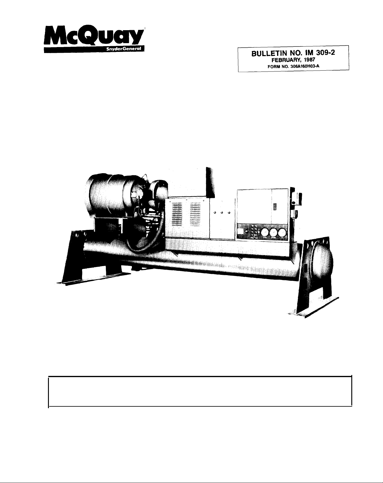
INSTALLATION AND
MAINTENANCE DATA
WATER COOLED
CENTRIFUGAL CONDENSING
Models SEH
046,048,050,063,079,087
UNITS
& 100
Installation and maintenance are to be performed by qualified personnel who are familiar with local codes
and regulations, and experienced with the type of equipment.
are a potential injury hazard. Avoid contact with them.
CAUTION: Sharp edges and
coil
surfaces
Page 2
Page 3
Page 4
GENERAL
The model SEH centrifugal condensing unit has been factory assembled, checked and shipped with holding charge
of refrigerant.
The purchase price of this equipment includes checkout
of the unit and initial startup by a McQuay service technician.
An integral part of the startup procedure includes instruction
of the responsible personnel in the operation and maintenance of this condensing unit.
It is most important that this equipment be properly
operated and maintained if it is to perform the operating service it was designed and built to provide.
McQuay offers equipment maintenance and/or inspection
programs that can be tailored to fit individual job requirements. Information on the various service programs is
available through the McQuay Service Department or your
local McQuay sales representative.
WARRANTY
The McQuay model SEH condensing unit is covered by a
standard published warranty which covers parts only. A complete published description of that warranty and its limitations
is provided in a warranty certificate included with each unit.
First year warranty labor can be purchased separately.
Check your local McQuay sales representative to establish
what additional coverage (if any) was purchased for your unit.
INSTALLATION
Information pertaining to the installation of model SEH condensing units is available in the installation bulletin
A copy of this manual was included in the envelope shipped
with the unit.
IM
308.
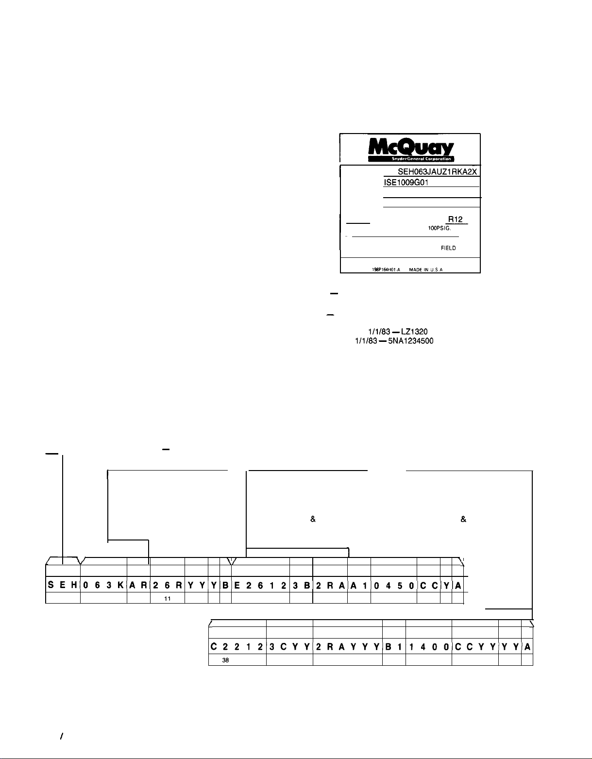
UNIT NAMEPLATE
Whenever requesting information or assistance on the model
SEH condensing unit, the unit model number, shop order
number and serial number should be copied from the unit
Figure 1.
Figure
1.
1 MODEL
STYLE
SERIAL
S.O. NO. SE1010
LBS. REFRIGERANT
I
I-
NOTE 1
model, style, serial, and shop order (SO.) numbers with your inquiry.
NOTE 2
occurred; sample serial numbers follow:
-
Whenever inquiring about this unit please forward unit
-
On January 1, 1983, a change in serial number coding
l Through
l After l/1183
SEH063JAUZlRKA2X
ISE1009GOl
5NA 1234500
FACTORY CHARGED
LEAK TEST PRESSURE
MOTOR COMPRESSOR CONTROLLER
AND OVERLOAD PROTECTION
SUPPLIED SEE SPEC PE-D4
111183 - LZ1320
-
5NA1234500
100 PSIG.
x
FIELD
is shown innameplate. A reproduction of this nameplate
UNIT MODEL DESIGNATION
-
COMPRESSOR
1
2 Compressor Size
3 Gear Ratio Code
4 Motor Electrical Power
5 Open-Drive Motor Description
6 Sound Control
7 Compressor Model Revision
r
-I-
r
7/
I
SEH063KAR26RYYYBE26123B2RAAlO45OCCYA
01 02030405 0607060910
”
1
2
-
SEH WATER COOLED CENTRIFUGAL CONDENSING UNIT, HERMETIC
3 4 5
11
12
13 1415 16 1716 192021 222324
\
\I
6 7
l
C22123CYY2RAYYYB1140OCCYYYYA
3738334041 4243 4445464746 495051 52 535455 56575659 6061 62 6364
MODEL CODING
EVAPORATOR
8
Evaporator Description
9
Tube Description
10
Head Description
11
Design Pressures
12 Leaving Water Temperature
13 Tube Sheet
14 Tube Cleaning System
15 Evaporator Model Revision
I
8
16 17 18 19
&
Head Material
9 10
11
252627 262930 313233 343536
CONDENSER
16 Condenser Description
17 Tube Description
18 Head Description
19 Design Pressures
20 Maximum Leaving Water Temp.
21 Tube Sheet
22 Tube Cleaning System
23 Condenser Model Revision
12 13 1415
&
Head Material
1
\
20
I
21
\
22 23
Page 4 I IM 309
Page 5

OPERATING INFORMATION
OPERATOR’S REPONSIBILITY
1.
Before operating the model SEH unit, become familiar with
the machine and accessory equipment.
2.
If possible, arrange to attend a McQuay centrifugal
operator’s school.
3.
After the unit has been checked out and approved for
operation by a McQuay centrifugal service technician,
work with him to learn how to prepare the system for start-
up. Start and stop the machine a number of times while
observing the operation of the interlock function. The interlock circuit must be satisfied before the compressor will
run. After operating the unit, place it in the shutdown
mode.
4.
Monitor operation and periodically inspect the equipment,
making routine adjustments where necessary.
5.
Maintain a log of operating conditions on a daily basis.
(Log sheets are available in pad form from McQuay.)
PRESTART SYSTEM CHECKLIST
NOTE: All of the following will have been checked out
by the McQuay startup technician during the initial
up procedure. Items preceded by an asterisk (*) should
always be verified by the unit operator on a routine
basis during the operating season.
Unit:
*1.
All service valves in operating position.
*2.
Control circuit energized.
Oil heaters have been operating for a minimum of 24
*3.
hours. Oil should be hot (approximately 130°F to
*4.
Oil charge visible in sightglass. (Mark level on sightglass
while machine is shut down; check level weekly.)
Check control circuit. Verify that all safety switches in-
l
5.
terrupt compressor starter holding coil.
l
6.
Water flow through the condenser is correct. (This can
be checked from condenser water pressure drop curves
available from McQuay.) On any system, water flow can
be reduced by a plugged strainer which can cause
operating problems and nuisance tripouts. New systems
are generally susceptible to blocked water strainers
caused by foreign material washing out of the piping.
Electrical:
1.
Wire size correct.
2.
Phase sequence correct.
*3.
Voltage within plus or minus 10% of rated compressor
nameplate voltage.
*4.
Phase voltage unbalance 3% or less.
5.
All wiring connections correct per unit wiring diagram.
6.
All electrical connections tight and made with copper
conductors and lugs.
l
7.
All starter parts move freely and contacts meet evenly.
8.
Motor overloads correct size. (Filled with dashpot oil,
sizes 079 and larger.) Do not attempt to field calibrate
adjustable overloads.
System:
‘1. Condenser pump rotating in right direction.
l
2. Condenser pump and motor lubricated.
start-
140°F).
*3.
All load equipment operative (main system fans, variable
volume boxes, etc.).
*4.
Tower fan(s) and controls operative.
*5. Tower water bleed and water treatment adequate.
STARTING
When the 115 volt AC control power supply is applied to the
control panel for the first time or after a power failure has occurred, the following will take place.
1.
The oil sump heater(s) will be energized.
2.
With “on-off” switch in either “on” or “off” position, its
indicating light will be out.
3.
The external failure light will be lit. In addition, the exter-
nal alarm circuit will be de-energized indicating a unit
problem.
4.
Push the reset button. The external failure light will go out
and the external alarm circuit will be reset (de-energized).
The pilot light in the “on-off” switch will now glow when
the switch is pushed to “on.”
The unit safety circuits have now been reactivated and
5.
the operating portion of the control circuit is ready to
function.
6.
A thermostat or other controller external to the unit panel
will, on a call for condensing unit operation, energize and
close relay SR. (Relay SR is field supplied and is located
external to the unit control panel.) Energizing this relay
will close its contacts and:
Start the oil pump.
When the oil pump develops oil pressure adequate to
close the oil differential pressure switch (50 psig above
suction pressure), the switch will close.
A time delay relay PLT injects a 10 to 60 second time
delay into the compressor starting control circuit and
prevents this portion of the circuit from being energized while oil pressure is being developed. At the end
of this delay, if the vane closed switch VC has closed,
relay MCR (located in the unit starter) is energized as
well as relay R3. The compressor starter will now close.
OPERATING
1. With the compressor running, capacity is controlled by
positioning variable inlet vanes located in the suction gas
inlet to the compressor. Opening the vanes allows the
compressor to pump more gas and, as a result, increases
capacity. Closing the vanes-reduces gas flow and reduces
capacity. The capacity control system is capable of
modulating the vane position to any capacity from 10%
to 100%.
2.
The inlet vanes are controlled by means of four different
devices. The capacity will be controlled by either temperature or pressure and the system design will determine
whether “a” or
always used on every unit.
a. A temperature sensor located in leaving airstream from
cooling coils or in leaving chilled water when a water
chiller is used.
b. A suction pressure transducer, sensing system suction
pressure variations, translates changes in pressure into
an electrical signal and through the control module
loads or unloads the compressor (opens or closes the
vanes).
“b”
below is used. Items “c” and
“d”
are
IM 309 I Page 5
Page 6

c. The solid-state control module in conjunction with a cur-
rent transformer located in the compressor motor
starter senses and will limit current drawn by the compressor motor, depending on the setting of the current
limit control. This controller will override either control
described in items “a” or
motor current exceeds its setting, open or close the
compressor vanes in response to changes in current.
Whenever the motor current is less than the setting on
the current limit controller, unit capacity control is
returned to the temperature sensor or transducer. The
current limit control can be set to limit current from 30%
to 100% of nameplate full load current. The control is
easily adjusted by a knob on the face of the control
module.
d. The low pressure override switch LPO, built into the
unit control panel, senses suction pressure and is set
to open at 2 to 5 psig above the low pressure safety
switch. Whenever the setting is reached, the override
switch opens and in turn opens control circuit
of the temperature controller. This in turn energizes SA
and de-energizes SB solenoids in the four-way valve.
Full oil pressure is applied to the unloader piston driving the vanes closed. This action will in most cases
catch a momentary “sudden” drop in suction pressure
such as may be caused by a slow acting expansion
valve, a drop that without this unloading feature would
open the low pressure switch and stop the compressor.
The LPO pressure switch is automatically reset; it will
close when the pressure rises to a safe limit and return
control of capacity to the temperature sensor or
transducer.
3. During normal operation, the compressor will continue to
operate and unload to a minimum of 10% until the cycl-
ing thermostat is satisfied. When this occurs, relay SR is
de-energized. Opening relay SR will then cause the liquid
line solenoid valve ahead of the expansion valves to close.
4. The unit control circuit incorporates a one-time
arrangement. The compressor will continue to run after
the system control thermostat is satisfied and has closed
the liquid line solenoid valve. The compressor starter
through the MCR relay is held in by a parallel circuit including a low pressure switch LPC and a set of normally
open compressor motor starter auxiliary contacts (2Mb).
As the compressor continues to run with the liquid line
solenoid closed, the system suction pressure is reduced
“b”
above and will, whenever
ABl-#6.2
pumpdown
to the setting of cutout LPC, opening the switch and
energizing relay MCR and stopping the compressor. The
pressure switch LPC is automatically reset, but it cannot
restart the compressor when its contacts reclose because
the compressor starter auxiliary contacts 2Mb are now
open. These contacts cannot reclose until the system sensor calls for cooling and energizes relay SR. Relay SR has
a set of contacts in parallel with low pressure switch LPC
and contacts 2Mb. These SR contacts when closed will
permit the operating portion of the control circuit to call
for the compressor to run.
5. The unit oil pump will continue to run for a minimum of
one minute after the compressor starter has been
energized. This will assure adequate lubrication for the
compressor during the
In addition, on the next call for cooling, the compressor
capacity control vanes must be in a closed position before
the compressor is allowed to restart. Contacts VD (auxiliary contacts located in the compressor starter) signal the
unload portion of the unit capacity control circuit and, if
the vanes were not fully closed when the compressor was
stopped, continues to energize solenoid SA and drive the
vanes to the closed position while the pump is still running. This will then permit the compressor to start on the
next call for cooling with a minimum delay. (The compressor will not start unless the vanes are in the closed
position.)
6. Rapid cycling of centrifugal compressor motors is not
desirable. A time delay through relay TDR is built into the
unit control circuit to prevent rapid cycling. Relay TDR will
prevent the compressor from restarting for a period of 20
minutes after the compressor is stopped unless the “automatic restarter after power failure with reduced timed off
cycle” accessory option is used.
7. In the event of a power interruption during unit operation,
the compressor is protected against damage by an
emergency oil reservoir and spring load piston. During normal operation enough oil is stored in the emergency
cylinder to lubricate the bearings during spindown. The
oil is forced into the various passages by a spring loaded
piston contained and compressed in the emergency oil
cylinder. The spring is compressed by normal machine
oil pressure while the compressor is running and on a loss
of power is available along with the piston to act as an
emergency oil pumping device.
spindown
period.
de-
de-
Page 6 I IM 309
Page 7

VANE OPERATION
Capacity variation for the unit is accomplished by opening
and closing vanes located in the suction inlet to the compressor. Vane movement is controlled by positioning a floating
piston to which the inlet vanes are linked. The piston (and
as a result the vanes) are positioned by building up oil
pressure on one side of the piston and draining or not draining the other side, depending on how far the piston must move
to satisfy the capacity requirements of the system.
Figures 2, 3, and 4 schematically illustrate the control of
the floating piston.
CONTROL SATISFIED
When the system capacity control is satisfied, an electrical
signal is sent to the control module calling for no change in
capacity. Such a condition is illustrated in Figure 2. The control module has de-energized both sections SA and SB of the
four-way solenoid valve. With both sections de-energized,
ports Cl and C2 are open and outlet port
#3
is closed. This
directs full pressure to both sides of the piston, holding it in
a stationary or satisfied position.
INCREASE CAPACITY
When the unit capacity is not high enough to satisfy the load
(such a condition is illustrated in Figure
3),
a signal from the
control module will energize section SB and de-energize section SA. This will drain oil from the right-hand side of the piston
and allow it to move to the right and open the vanes. Oil in
the right-hand side of piston will continue to drain through
#3
the open port C2 and outlet
and the piston will continue
to move to the right until the control module de-energizes section SB, thus holding the piston at that position.
DECREASE CAPACITY
When the unit has been running at a higher level of capacity
and the load falls off, the system is required to reduce com-
pressor capacity. Such a condition is illustrated in Figure 4.
The control module energizes section SA and de-energizes
section SB. This permits oil to drain from the left side of the
piston through open port Cl to the outlet
#3.
With section
SB energized, full oil pressure is applied to the right end of
the compressor piston, moving it to the left. The piston can
be stopped at any point in its leftward movement when the
capacity is satisfied and the control module signals to
de-
energize SA.
Figure 2.
COMPRESSOR
UNLOADER
CYLINDER
I
Figure 3.
1
OPENING
Figure 4.
rzzq
- OIL UNDER PRESSURE
-
FLOATING PISTON
LINKED TO INLET VANES
-
OPENS VANES
-
CLOSES VANES
FOUR WAY
SOLENOID VALVE
J
LOCATED IN
NOTE ADJUSTABLE
NEEDLE VALVES
INTEGRAL
WITH FOUR WAY
SOLENOID VALVE
ARE NOT SHOWN
1
DRAIN FROM PISTON
--)
-)
Xl INLET
-
r
X3 OUTLET
oc2
-LEGEND-
OIL SUMP PRESSURE
PISTON DRAIN TO OIL
-
SECTION
ENERGIZED
SECTION
DE
-- PUMP
SECTION
“SE”
DE-ENERGIZED
SECTION “SA”
DE-ENERGIZED
FROM OIL
PUMP
DISCHARGE
VALVE
I--)
“SE+”
“SA”
ENERGIZED
FROM OIL
-PUMP
DISCHARGE
VALVE
TO OIL
PUMP
SUMP
SUMP
The above descriptions are simplified versions of what actually happens, neglecting the complicated control function
provided by the control module as it pulses to control the action of solenoids SA and SB.
METERING VALVES
The hydraulic control system utilizes needle type adjusting
valves built into the four-way solenoid valve. These valves
are used to adjust the response time for the floating piston
to move through its full length of travel. The valves are factory set and under normal operating conditions should not
need to be reset. Attempts to reset the valves by unqualified
personnel will result in very poor operation of the capacity
control system.
DISCHARGE
VALVE
IM 309 I Page 7
Page 8

CONTROL CENTER
The control center contains all of the unit protective controls
and most of the operating devices. Table 1, “Control Summary” (on page 15 and
mation including electrical diagram symbol, control description, setting, reset information, location, signal light, and information on the control function.
Eleven indicating lights are utilized on the unit control
panel. Nine of these lights are normally out and only glow
when a safety circuit has tripped.
Repeated tripping of a given control should be investigated
by a competent service technician to avoid costly damage.
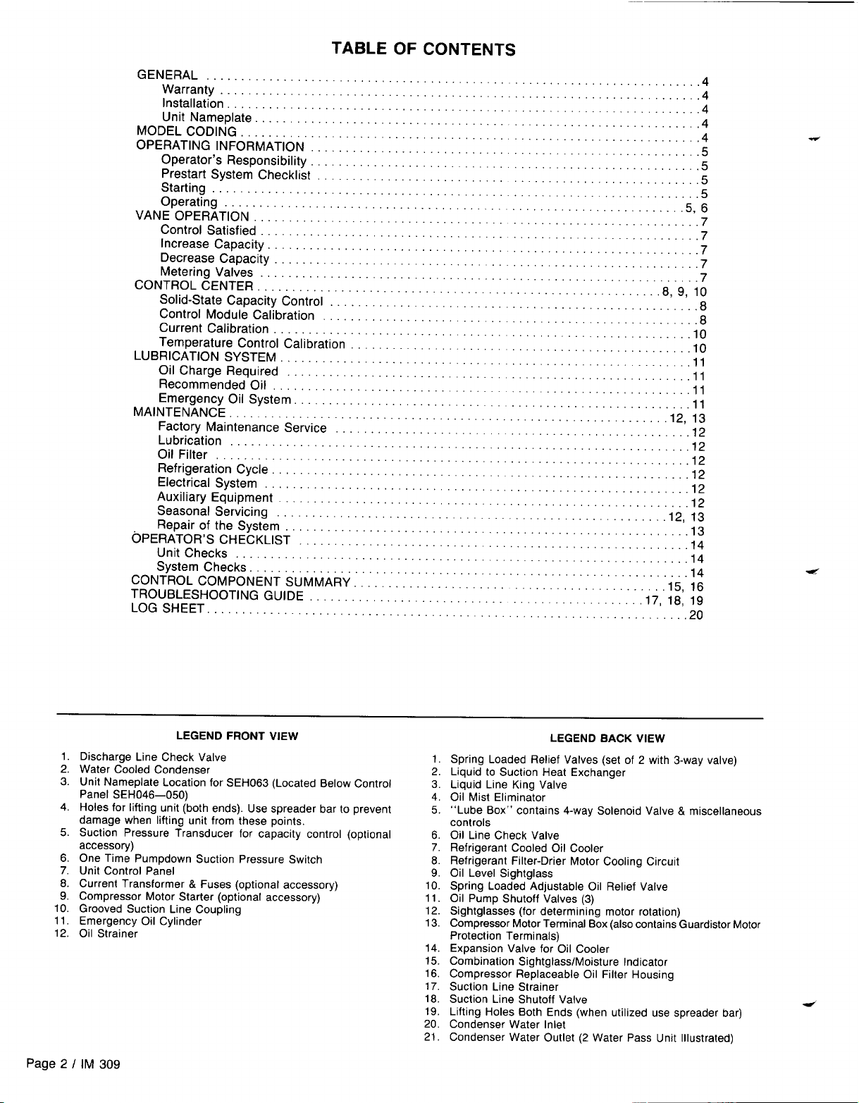
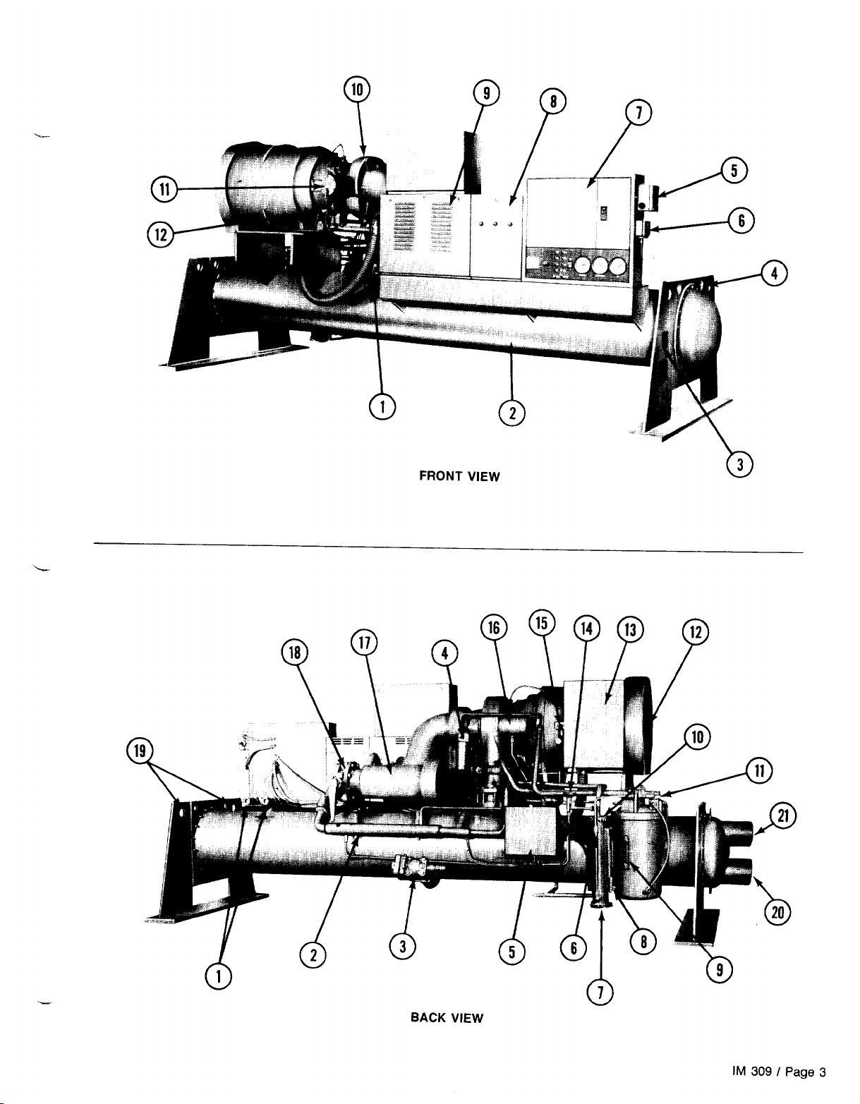
Details of the control center are shown in Figure 5.
Two important safety circuits incorporated in the model
SEH control system are:
1.
GUARDISTOR
motor protection against damage from motor overheating.
Thermistors buried in the motor winding are supersensitive to changes in motor winding temperature. These
thermistors have been calibrated to de-energize the GDR
(Guardistor relay) whenever the motor winding temperature exceeds the maximum allowable.
The motor protection system, because it is sensing internal motor winding temperature, provides positive protection against motor damage from such heat causing problems as loss of motor cooling, low voltage, etc., and is
in our opinion the finest motor protection system available.
The Guardistor control circuit is a manual reset system
which when actuated will require manual resetting by
pushing the reset button on the unit control panel.
In the event of a power failure to the unit or control panel,
the Guardistor relay will trip and require manual resetting
when power is restored.
2.
SURGEGARDTM -
mal operating condition for a centrifugal compressor.
Under some abnormal operating conditions, a surge condition can occur and if allowed to continue can cause compressor damage. A surge is caused by many things such
as dirty condenser tubes, increase in condenser water
temperature above design, or any other factor which can
act to increase the pressure difference between suction
and discharge pressure.
The McQuay centrifugal compressor is protected
against damage from a surge condition by a unique protection system which senses a surge condition should it
occur and shuts the machine down before damage can
result.
Once shut down, the unit should not be operated until
the cause of the surge has been determined and corrected.
Whenever the machine has been stopped as a result
of a surge condition, the
control panel will glow.
SOLID-STATE CAPACITY CONTROL
The solid-state control module combines temperature and
current limit control in a single solid-state package. In addition, indicating lights on the module indicate whether the control is calling for the compressor to load or unload or whether
the current override feature is in control. By setting a switch,
it is possible to place the unit under manual or automatic con-
trol of unloading.
The control module, through the capacity control system,
is capable of extremely close control
point temperature. Dials provide for manual adjustment of
the unit control setpoint and/or for limiting the current drawn
by the compressor motor at any level between 30% and 100%
of rated full load current.
The standard control module described above has the abili-
ty to:
16),
contains general control infor-
Motor Protection - Provides positive
A surge or rotating stall is not a nor-
SurgeGard
indicating light on the
( *
0.5”F) of design
set-
1. Accept a remote signal to automatically reset the capacity control point(s) (for example) in response to changes
in return air or outside air temperature, etc.
2. Remote setting of unit cycling control setpoint(
3. Limit unit capacity in response to a remote electrical de-
mand controller.
4. Ability to accept a signal to balance the load on multiple
units operating on a common signal.
All of the above are accessory options which require addi-
tional components not a part of the standard control circuit.
The pulsing action built into the electronic control module,
coupled with needle valve adjustment of the hydraulic portion of vane control, provides a very stable temperature control arrangement. During normal operation, it will take approximately 3 to 5 minutes to move from minimum to maximum
capacity and
capacity.
The condensing unit can be applied to many different cooling applications and is adaptable to many different types of
control systems. The loading and unloading can be in
response to variations in temperature at a remote location
or from a change in system suction pressure. The particular
control arrangement used will be incorporated as a part of
the total job control system. Details on the total system control should be available in the job file. The vane control system
is explained on page 7.
CONTROL MODULE CALIBRATION
The control module supplied as a standard part of the unit
control center is a solid-state electronic device which operates
from a 24V A.C. power source. Except for its external sensor(s) and a 5 volt (full load) signal from a current transformer,
and resistor located in the compressor motor starter, it is completely self-contained. The module can provide many features
and functions, some of which are:
1.
Proportional temperature control (within f
setpoint).
2.
Current limit control (manually adjustable).
3.
A pulse rate adjustment which permits the module
response speed for loading or unloading to be varied to
meet application requirements encountered on different
systems and/or applications.
4.
A “ramp-up” adjustment which can be utilized at compressor startup to control the time to load and the point
at which the controlled loading begins. For example, this
adjustment can be used to reduce the power that would
be consumed by the unit if it were allowed to load the
machine without a time restriction.
5.
Indicating lights which glow when the controller is calling
for loading (green), unloading (red), or current override
(amber).
6.
A selector switch to permit manual or automatic control
of unit capacity.
7.
A selector switch to permit manual control of loading or
unloading.
8.
Can be adapted to accept a signal to reset the control point
in response to a change occurring at another location such
as outside air, return chiller water or energy management
device.
9.
Can be adapted to unload in response to a signal from
an energy management device used to shed electrical
power loads. The compressor capacity can be reduced
as a function of building entrance power.
1
minute to move from maximum to minimum
0.5”F
of
Page 8 I IM 309
Page 9

Page 10

The control module is factory calibrated and should not nor-
mally require field calibration. In the event calibration must
be checked, a procedure covering the steps required for both
current and temperature calibration is outlined in the follow-
ing paragraphs.
CURRENT CALIBRATION
1.
Equipment needed -An accurate
Start the unit and place the control module selector
2.
amprobe
or ammeter.
switch in the manual position.
Open the starter door and place the amprobe on the
3.
power lead drawing the highest current on the load side
of the starter.
4.
Remove the control module cover.
Set current demand limit selector switch clockwise
5.
(m)
against the stop (100%).
Set the blue current limit calibration screw (located just
6.
to the left of the temperature control stem) to the full
counterclockwise
7.
Check the compressor motor nameplate rated load
amperes
(RLA)
(0)
position.
against the amperage reading on the
am-
probe. Manually adjust the load until the amperes drawn
by the motor match the motor rated load amperes.
When the nameplate and amprobe ampere values are
8.
equal, turn the current limit calibration screw clockwise
until the amber light just comes on and stop. This places
the unit in current hold. The internal circuitry of the
module will now insure that, should the current increase
to 105% of rated load amperes, the controller will unload
the compressor.
To verify that the calibration is correct, manually unload
and then reload the compressor to the rated load ampere
value and verify that the current override light glows. The
current limit control portion of the module is now in
calibration.
Check the knob setting. If it needs correcting, snap the
9.
top off the control knob, loosen the screw and rotate the
knob to indicate 100% of current. Tighten screw and
replace top.
Replace module cover, remove amprobe and close
10.
starter door.
TEMPERATURE CONTROL CALIBRATION
Equipment needed - Temperature calibration resistor
1.
rated 951 ohms at 1%.
Start the unit.
2.
Remove sensor leads from terminals ISA and +6.2
3.
located on the control module upper terminal strip.
Connect the calibration resistor across terminals ISA and
4.
+ 6.2.
Check the voltage across terminals
5.
101
and COM on the
upper terminal strip. Manually load the compressor until a reading of 7.5 volts is obtained across these
terminals.
Switch the control to auto and turn the temperature con-
6.
trol knob to a point where both the load and unload lights
remain out.
Remove the control stem and position the pointer until
7.
it shows 47 on the temperature scale.
Snap the top off the control knob, loosen the screw and
8.
rotate the knob until it indicates 47 on cover temperature
scale. Tighten the screw and replace the cap.
Remove the calibration resistor and reconnect the sen-
9.
sor leads back onto terminals ISA and + 6.2.
Replace the control module cover and tighten cover
10.
screw.
The method for temperature calibration covered above will
result in a reasonable calibration. If closer calibration is required, McQuay Service has specialized equipment which
will permit a finer adjustment to be made.
Page 10
/
IM 309
Page 11

LUBRICATION SYSTEM
A separate motor driven oil pump assembly supplies oil at
controlled temperature and pressure to all bearing surfaces
and in addition is the source of hydraulic pressure for the
capacity control and emergency oil supply.
The unit control system on a call for cooling will not permit
the compressor to star-l until oil pressure has been established
for at least 1 minute. When the system controller is satisfied
and stops the compressor, the oil pump runs for another
minute to assure adequate lubrication during spindown. In
addition, during this period the compressor is unloaded
through the action of the vane closed switch VC. The com-
pressor will then be ready to start unloaded on the next call
for cooling.
The oil pump is completely self-contained and located in
the oil sump. On model SEH046, 048 and 050 units, it is
located inside the compressor housing. For model SEH063
units the oil pump is located in the oil pump assembly which
is mounted at the rear of the unit adjacent to the condenser.
In either case, it includes the pump, pump motor, oil heater
and oil separator. The model SEH063 includes shutoff valves
for discharge, oil return and suction.
Figure 6. Oil Circuit
sump. On model SEH063 units oil from the gear housing and
capacity control is dumped into the scavenger line and returned to the oil sump. Oil as it circulates in the oil system
will always have some refrigerant mixed in it (because of the
ability of oil and refrigerant to mix in all proportions). Most
of this refrigerant flashes from the oil as it enters the oil sump
or is driven from the oil by the oil heater. This refrigerant gas
as it is removed from the oil sump passes through a centrifugal oil separator located on top of the oil pump rotor.
The oil sump is vented to the suction side of the system
just ahead of the compressor wheel eye. Gas flowing from
the oil sump has to pass through the spinning oil separator
where entrapped oil is removed by centrifugal force and is
thrown back to the oil sump. The refrigerant gas flows on
through to the compressor suction.
The main oil sump on all units is provided with an electric
heater and, in addition, the model SEH063 units also include
a heater in the gear housing.
CAUTION
THESE OIL HEATERS MUST REMAIN ON AT ALL
TIMES THE COMPRESSOR IS NOT RUNNING.
SHOULD AN EXTENDED POWER LOSS OCCUR
ENERGIZING THE HEATERS) AND ALLOWING THE
OIL TO COOL, IT WILL BE NECESSARY WHEN
POWER IS RESTORED TO KEEP THESE HEATERS
ENERGIZED FOR A MINIMUM OF 24 HOURS BEFORE ATTEMPTING TO RESTART THE COMPRESSOR.
(DE-
Oil is pumped through an externally adjustable oil relief
valve which is factory adjusted to limit the discharge oil
pressure from 100 to 110 psig above the operating suction
pressure. After leaving the relief valve oil flows through a
refrigerant cooled oil cooler where the temperature is reduced to approximately 90°F to 100°F. From the cooler it
passes through a replaceable 5 micron oil filter located in the
compressor casting. On model SEH046,048 and 050 units
the oil first passes through the oil filter and thrust pump before
entering the oil cooler. Filtered oil is then distributed through
internal passages in the compressor casting to the control
system and before entering the bearings. On model SEH063
units it passes into the thrust pump where the oil pressure
to the bearings is boosted.
Oil leaving the compressor and motor bearings is releas-
ed under pressure into the low pressure gear housing where
some of this oil vaporizes. This oil vapor is used to lubricate
the gearing. The remaining oil leaving the bearings drops to
the bottom of the gear housing where it is drained to the oil
If conditions require the compressor to be restarted immediately, it will be necessary to drain the system oil and
recharge the unit with new oil which is free of refrigerant.
The low oil temperature thermostat LOT (set for 120°F) supplied as part of the unit safety controls will, if adjusted properly, prevent the compressor from starting with cold oil. This
thermostat is a manual reset type and when tripped will cause
the oil temperature light to glow.
OIL CHARGE REQUIRED
Quantities of oil required for model SEH units as well as the
recommended oil specifications are:
.1.75
Models SEH046, 048, 050
Models SEH065, 079, 087 .8 gallons
Model SEH 100
RECOMMENDED OIL
Models 046, 048, 050, 063, 079, 087:
Suniso
Model 100: Suniso 5GS or Texaco 100 WF
EMERGENCY OIL SYSTEM
An oil cylinder with a spring loaded piston is incorporated in
the compressor casting on all sizes of compressors to supply emergency lubrication for bearings in the event of a power
loss. During normal operation, pressure from the oil pump
fills the emergency oil cylinder and compresses the
piston/spring assembly contained in the cylinder. On a loss
of power (and as a result, a loss of oil pressure), oil is forced
into the bearing lubrication passages as the spring behind
the piston expands and forces oil from the emergency
cylinder. The emergency oil system contains an adequate oil
supply under pressure to assure adequate bearing lubrication during the spindown period.
4G/4GS
or Texaco Capella 68WF
.11
gallons
gallons
IM 309 / Page 11
Page 12

MAINTENANCE
It is important that this unit and the air conditioning system
it is part of receive adequate maintenance if full equipment
life and all system benefits are to be realized.
On a new system, maintenance should begin with a
followup inspection of the system after 3 to 4 weeks of normal
operation. This inspection can be performed by McQuay Service on an invoiced basis.
FACTORY MAINTENANCE SERVICE
McQuay offers a variety of maintenance services through its
nationwide service organization. These contract services include regular inspections and emergency service by factory
trained technicians. Services are available around the clock
to keep your equipment running in top condition.
With a McQuay Assured Maintenance contract, all parts,
labor and materials are furnished
-
with no additional cost
to the customer.
It is widely recognized that a good maintenance program
is the essential first step in controlling energy costs. And
through McQuay’s Assured Maintenance and Energy
Management programs, the owner is assisted in establishing
a comprehensive energy management plan to meet his
needs. For further information concerning the many services
available contact your local McQuay Service representative.
LUBRICATION
Once the unit has been checked out and is placed in service, no additional oil should be required. The oil level in the
oil sightglass should be marked when the system is shut down
and the level checked periodically. The oil sightglass level
should be approximately full when unit is shut down and about
l/3
full while the unit is running.
OIL FILTER
The oil filter must be changed annually. We do not recommend that untrained personnel attempt to replace the filter.
The filter is contained in a system under refrigerant pressure,
as well as oil pressure. If proper care is not taken when changing the filter, personal injury could occur. In addition, air
and/or moisture could enter the system and cause equipment
problems.
1. Model SEH046, 048 and 050 units have an internal oil
pump and require that the system refrigerant charge be
pumped into the condenser before attempting to change
the filter. After the unit is pumped down, break the seal
on the oil filter access cover and permit the pressure to
bleed off before removing the cover. After replacing the
filter, crack open the condenser liquid valve and permit
the pressure to build up and purge the oil filter housing.
Replace the cover and check for leaks.
2. Model SEH063,079,087 and 100 units have an external
oil pump assembly. Close the oil pump discharge valve.
Loosen the flair fitting feeding oil to the filter and bleed
off the pressure by purging slowly. When the pressure has
been relieved, remove the cover and replace the filter.
When reassembling, vent as much air as possible from
the oil lines before placing the compressor back into
operation.
REFRIGERATION CYCLE
Since the model SEH unit has a semi-hermetic compressor
and utilizes R-12 or R-500 refrigerant, normal system
pressures, whether the system is operating or shut down, will
always be above atmospheric. Unit maintenance generally
will consist of proper inspection and maintenance of an
operating log. Visual inspection of oil level as shown in the
sightglass and noting operating suction, discharge and oil
pressures will generally indicate if the unit operating characteristics are changing.
ELECTRICAL SYSTEM
Generally, maintenance of the electrical system only involves
keeping operating controls clean and electrical connections
tight. In addition, the following items should be inspected:
The compressor amperage (current) drawn should be corn-
pared to the nameplate rating. Normally the current read
will be less than nameplate since the nameplate value
represents design full load current.
Check that oil heaters are operative. Heaters are cartridge
type and can be checked by an amperage reading. They
should be energized whenever the compressor is not
operating. When the compressor runs, the heater should
be automatically de-energized.
Once a year all safety controls except compressor
overloads should be made to operate and the operating
point checked. Any control as it ages can shift its operating
point and this should be detected.
Pump interlocks and flow switches should interrupt the
control circuit cleanly. A chattering flow switch can be a
source of trouble as well as irritation.
Motor starter contacts should be inspected and cleaned
annually. All terminal connections should be tightened.
Compressor motor resistance should be checked annually.
This will track any insulation deterioration that might be
occurring.
AUXILIARY EQUIPMENT
It is important that auxiliary equipment used in conjunction
with the model SEH unit be adequately maintained. Malfunctions in this equipment often affect the operation of the condensing unit. For example, improperly maintained air filters
in the system can restrict airflow to the cooling coils and as
a result cause suction pressure to fall to a point where a
nuisance
tripout
on the low suction pressure cutout could occur. Items such as the following should be checked and
maintained.
1.
All filters must be cleaned or replaced. The frequency
of this service will vary with different installations.
2.
Keep condenser pump water strainer clean. Inspect and
service on a regular basis.
3.
Maintain cooling tower water treatment to limit buildup
of scale in condenser tubes.
4.
Inspect and maintain operating portion of variable volume
boxes when used.
5.
Inspect condenser tubing at least annually (or more often)
depending on condenser scaling conditions.
6.
All fans and belts checked and adjusted.
7.
All condensate drains clean.
8.
All motors lubricated.
9.
All electrical connections tight.
10.
Starter contacts clean and mechanism moves freely.
SEASONAL SERVICING
At the end of the cooling season and before the unit is started
in the spring, the following service procedures should be
completed.
Annual Shutdown
When the unit may be exposed to freezing temperatures,
water piping should be disconnected from the supply and
drained of all water. The condenser is not self-draining.
Dry air blown through individual condenser tubes will help
in forcing the water out of the condenser.
Pa
.ge
12 / IM 309
Page 13

When it is possible to have the unit and/or piping exposed to freezing temperatures, the only sure method of
protection is forced circulation of an antifreeze solution
through the water circuit.
When a cooling tower is used and the water pump will be
2.
exposed to freezing temperatures, be sure to remove the
pump drain plug and leave it out so that any accumulation of water will drain away.
Take measures to prevent the water supply line shutoff
3.
valve from accidentally being turned on.
Open the compressor disconnect switch and remove the
4.
Fusetrons. If a control circuit transformer is used for control power, the disconnect must remain on to supply power
to the oil sump and gear housing oil heaters. Set the com-
pressor on-off switch to “off.” To guard against the
possibility of an accidental compressor start, remove relay
R7 from the control panel (see Figure 5).
Annual
1.
2.
StartuD
Before proceeding with the seasonal startup procedures,
we recommend that the compressor and oil pump motor
resistance be checked. Annual checking and recording
of this resistance will provide a record of deterioration in
the motor winding insulation should it occur. All new units
have a compressor stator resistance well over 100
megohms between any motor terminal and ground.
Whenever a marked change in resistance shows or
uniform readings of less than 5 megohms are obtained,
THE UNIT SHOULD NOT BE STARTED SINCE MOTOR
FAILURE WOULD BE PRACTICALLY CERTAIN. In all
probability, the motor will have to be repaired or replaced. Your McQuay Service representative should be
called for recommendations and/or repair.
The unit control circuit should have been energized at all
times. If the control circuit has been shut off and the oil
is cool, the machine should not be started until the heaters
in the oil sump (and gear casing SEH063 only) have been
energized for a minimum of 24 hours. If it is necessary
to start the machine without waiting 24 hours, then the
oil in the unit should be drained and replaced with fresh oil.
3.
Check and tighten all electrical connections.
4.
Install Fusetrons in the main disconnect switch (if they
have been removed).
5.
Replace relay R7 (if it was removed).
6.
Replace drain plug in water pump if it had been removed.
7.
Reconnect water lines, turn on supply water and check
for leaks.
8.
Clean and flush water tower.
Make sure tower bleed is adequate.
Be sure water treatment is adequate to prevent a
buildup of solids in the condenser. Air circulated
through the tower contains many contaminants which
are flushed out by the tower water. The use of untreated
water in most installations can result in a reduction of
heat transfer in the condenser tubes or damage to the
tubes as a result of corrosion, erosion, sliming, scaling, or algae formation.
Recommendation: The service of a competent water
treatment organization be obtained to determine what, if
any, water treatment is required and their recommendations implemented.
McQuay assumes no responsibility for operating pro-
blems or damage occurring as a result of untreated condenser water.
9.
Clean all surfaces and remove all litter. A clean, well maintained unit is the sign of a good operator.
REPAIR OF THE SYSTEM
Information on pumping unit down, pressure testing, leak
testing, evacuation and charging is contained in installation
manual IM 308.
IM 309
/
Page 13
Page 14

OPERATOR’S CHECKLIST
UNIT CHECKS
1.
Suction, discharge and oil pressure normal.
2.
Oil level correct.
Voltage within tolerance (plus or minus 10% of compressor
3.
nameplate rating). Phase unbalance should not exceed
3%.
4.
Motor amperage proper for load conditions.
Vanes open and close under manual and automatic
5.
control.
Motor current limiting control operational.
6.
Safety interlocks interrupt compressor operation.
7.
Unit cycling thermostat set 3 to 5 degrees below unit con-
8.
trol setpoint.
SYSTEM CHECKS
1. All motors checked for voltage and running amperes.
2. All pumps and motors lubricated.
3. Water strainer(s) clean.
4. All fans checked, belts tight, bearings lubricated.
5. Air filters clean.
6.
All electrical connections tight, starter contacts clean,
starter movement proper.
7.
The system expansion valves should have been properly
sized and selected for the anticipated design and operating
loads for which they are expected to function. The valves
used must be capable of controlling refrigerant flow to the
evaporator over the full capacity modulating range of the
centrifugal compressor (10% to 100%).
Particular attention should be paid to the operation of
the unit and system during the initial cooling period. During this period, if the expansion valves have not been properly sized and selected or the total system load is
substantially less than anticipated, problems will develop.
They should be caught and corrected as quickly as
possible.
The operator should double check that the expansion
valve control bulbs have been securely clamped to the suction line and that the bulbs are well insulated. An improperly sized or faulty operating expansion valve will lose control of the refrigerant feed to the cooling coils and can be
the cause of low suction pressure, as well as overfeeding,
either of which could cause nuisance tripping or compressor damage.
Page 14 I IM 309
Page 15

TABLE 1. CONTROL COMPONENT SUMMARY - STANDARD APPLICATIONS
CONTROL
Alarm Relay
Chiller Pump,
Waterflow interlocks
Cold Oil Temperature
Switch Section
Condenser Pump,
Waterflow Interlocks
Flow Switch
Time
Delav
Guardistor Relay
Hot Gas Override
Solenoid
Hot Gas Solenoid
Hot Gas Thermostat
High Oil Temperature
Switch
High Pressure
High Suction Temp.
Switch
High Discharge
Temo.
Switch
Interval On Timer
Low Casting Temp.
Thermostat
Injection
Liquid
Solenoid
Load Meter
Low Oil Temp.
Thermostat
Low Pressure
Switch
Pumpdown
Switch
Low Pressure
Override Switch
Load Recycle
Thermostat
Liquid Line Solenoid
Valve
Oil Pump Contactor
Motor Control
Relay
Motor Cooling
Solenoid Valve
Oil Cooler
Solenoid
Oil Pressure
Diff.
Oil Pump
Overload
Oil Pump Safety
Timer
Control
Switch
SYMBOL SETTING
R9
CHWI None
COT
CWI
FSTD
GR
HGO None
HGS
HGT
HOT
Swatch HP
HST
HT
IOT
LCT
LIS None None Refrig.
LM None None Panel None Drsplays
LOT
LP
LPC 2-5 psig
LPO
LRT
LS
MCR
MCS
ocs
OD
OL
OPT
105°F
Field Set
140°F
Temp.
Function Section
150°F Auto/Man
225°F Manual
Field Set
110°F
130°F
Function
above LP
2
above LP
Field Set
IM None None
50 psig Auto/Man
opens
Adjust. Box Press. circurt.
60 sec.
None
None
None
None
None None
See
See Manual Switch
Ps’g
None None
None None
None None Refrig. None
None None Chiller None
Non-
RESET
(Note 1)
Auto/Man
Auto/Man
Auto/Man
Auto/Man
Auto
Auto/Man
None
None
Manual Switch
(Rt2)
Manual Switch
None
Auto
Auto Temp.
Auto Side of
Auto
None Temp. Load
Auto/Man
Auto/Man
LOCATION
Relay None
Section
Field Ext.
Suoolied
Switch
Field Ext.
Supplied
Relay
Section
Relay
Section
Hot Gas
Piping
Hot Gas
Piping
Condenser
Frame
Section Temp.
Temp.
Section
Switch High
Sectron Temo.
Lead/Lag
BOX
Temp.
Sectron
Piping
Section Temp.
Sectron
Panel one-trme pumpdown
Switch None
Section
Section Recycle
Freld
Supplied
Relay
Sectron
Starter
Piping
Piping
Lube
Box
Lube
Relay
Section Press
SIGNAL
LIGHT
Actuates circuit for remote alarm.
Prevents chiller operation until chilled water pump is energized and
Fall
flow is established.
011
Temp.
Motor
Temp.
None
None
None
Disch.
Press.
Surgegard Stops compressor when suction temperature exceeds setting; prevents
None
Temp.
None
Press.
None
None
None
Comp.
Press.
Stops compressor if oil temperature entering compressor drops below
setting.
R114
Templifiers only.
Prevents chiller operation until condenser water pump is energized
Fall
and flow IS established.
Ext.
Delays water flow loss for three seconds to prevent false shutdown.
Fail
Stops compressor motor when winding temperature exceeds limit.
Opens hot gas bypass at starting of 2nd compressor oil pump to
reduce starting head. Dual compressor units only.
Opens hot gas bypass from discharge to evaporator, providing false
evaporator load. Helps prevent surge conditions.
Energizes hot gas solenoid on drop in water temperature entering
evaporator (senses entering condenser water in Templifier).
Oil
Stops compressor if oil temperature entering compressor exceeds
ing (reset auto/man with
Stops compressor when discharge pressure exceeds setting. Set
lo-12
psig above design saturated condensing pressure (not to ex-
ceed 90% condenser nameplate maximum working pressure).
compressor surge (CEO50 compressor only).
Stops compressor when discharge gas temperature exceeds setting
Actuates
trme
Oil
Opens liquid injection valve after compressor starts-standard on
CE126. (Optional for CE063, 079,
Oil
LOW
Overrides control module, unloads compressor when suction pressure
compressor 3°F below control point. (See PF manual for
setting.)
or controller is satisfied.
Run
energized.
Opens to feed liquid refrigerant for motor cooling during compressor.
operation.
Oil
drops to
Oil
Oil
close within 60 seconds after oil pump starts.
crrcurt
delav.
Assures
(CE126 compressor
Prevents compressor start with cold oil. Set as high as conditions
allow. Protects compressor bearings from refrigerant diluted oil.
Stops compressor when suction pressure drops below setting. Set
5 psig below shop order suction pressure.
Stops compressor when suction pressure setting is reached-part of
.-.
approaches setting of LP cutout-prevents nuisance trip.
Starts/stops compressor in response to load changes-stops
Opens on call for cooling or
Starts oil pump when energized.
Energizes compressor motor starter when unit control circuit is
Opens valve to permit coolant flow during oil pump operation.
Stops compressor when difference between oil and suction pressure
Stops oil pump and compressor if oil pump motor overloads electric
Stops pump by interrupting safety circuit if vane closed switch fails to
for specific time and returns to normal position after
mrnrmum
compressor casting temperature at startup.
onlv).
percent of full load amps when compressor runs.
control feature-SEH units only.
settmg.
Closes at 60 psig to permit compressor start.
FUNCTION
R114
Templifiers).
heatrng.
067,
100) (Not used on
Closes when system thermostat
RI14
LRTP
units).
set-
IM
309 / Page 15
Page 16

TABLE 1 Continued. CONTROL COMPONENT SUMMARY - STANDARD APPLICATIONS
CONTROL
Oil Pump Time
Delay Switch
Pushbutton Switch
Prelube
Timer
Protective Signal
Interlock
Phase Voltage Relay
Range Shift
Resistor
Capacity Control
Solenoid
Capacity Control
Solenoid
Starts Counter
Surgegard Relay
System Monitor
Timer
Sump Oil
Thermostat
Sequence Relay
Source Water
Thermostat
Anti-Recycle Time
Delav
Relav
Transition Resistor
Protector
Pilot Expansion
Valve Solenoid
Vane Closed
Switch
Vane Delay
Contacts
Voltage Relay
SYMBOL SETTING
RESET
(Note 1) LIGHT
OTD
PLT 60 sec.
PVR
RSR
SGR
SOT
SWT
TDR
TRP
TXS
60 sec.
PB None
PS
SA None None Lube
S0
SC None None Panel None
SM
SR
vc 40 psig
VD None
VR
None None
None
None
None None Lube
Non-
Adiust. Section
60 sec.
140°F
None
Field Set
20
Min.
None
None None
Differential
Non-
Adjust.
None
None
None
Auto/Man
None
Auto/Man
Auto/Man
Auto Control None
None
Auto
None Relay
Auto/Man Starter
None Lube
None
None
LOCATION
Relay
Section
Switch
Section
Relay
Section
Starter
Starter
Control
Module
Box
BOX
Relay
Relay Ext.
Section
BOX
Field
Supplied
Temp.
Section
Section
Piplng
Box
Starter
Lube
Box
SIGNAL
None
None
None
Ext
Fail
Ext.
Fail
None
Module Part of
Red
Module Part of
Green
Surgegard
Fail
None
Load
Recycle
None
Ext.
Fail
None
Oil
Press.
None
None
FUNCTION
Keeps pump running for 60 seconds after compressor is stopped.
Pushbutton switches reset the safety circuit when the RESET button
on the control panel is pushed.
Provides a pre-lubrication period for bearings prior to compressor
start.
De-energizes system
delta contactor
Protects compressor against damage from single phase, phase
sal or undervoltage.
Provtdes
temperature range shift for control module on Templifier
units.
4-way
on control piston and closes vanes-UNLOAD.
4-way
on control piston and opens vanes-LOAD.
Counts number of compressor starts
Works with thermistor to sense impeller cavity temperature. Protects
oressor
from a
If compressor fails to start in 60 seconds after system monitor IS
energized, system monitor terminates start effort.
On
units with
maintain set temperature.
Relay controlled by system thermostat (or other control) to start unit
on call for
Stops compressor when water temperature entering evaporator is too
low for
Prevents compressor from restarting for 20 minutes afler previous
shutdown.
Abort compressor starting sequence if starter fails to make transition
from star to delta within 1 second.
Opens when 2nd compressor starts, closes when 2nd compressor
stops (PF063 only).
Prevents compressor starting unless capacity control vanes are closed
(fully
Auxiliary contacts in compressor starter prevent compressor loading
and liquid solenoid valves from opening (SEH units only) until com-
pressor motor connected across the line.
Disconnects
coolmg.
pracbcal
unloaded).
monitor
timer when compressor starter closes
rever-
solenoid valve. When energized, applies full oil pressure
solenoid valve. When energized, applies full oil pressure
surqe
ICE063 thru 126
refrigerant cooled oil cooler, controls oil sump heater to
heat recovery.
011
pump motor capacitor after start (CEO50 only).
comoressors).
com-
NOTE
#l
Auto-This control automatically resets itself
Manual-This control requires manual reset which is done mechanically with RESET button
Auto/Man-This control automatically resets itself but electrical lockout circuit
NOTE #2
This table contains all standard and most optional control components used in
Controls for specific units can be identified by referring to control diagram and/or the unit control center.
Page 16 / IM 309
requires
that RESET button be pushed to reset the circuit.
McQuay centrifugals.
All listed controls are not necessarily used on all
units.
Page 17

Page 18

Page 19

Page 20

 Loading...