

Page 1
TECHNICAL MANUAL
Chilled Water Fan Coil Units
MWM, MCK, MCM, MCC, MDB Series
MWM-LW MCK-EW
MCK-CW
MCC-CW
MCM-DW/EW
MDB-BW
V1
Page 2

Page 3

Table of Contents
“McQuay” is a registered trademark of McQuay International. All rights reserved.
@ 2013 McQuay International. All rights reserved throughout the world.
Bulletin illustrations cover the general appearance of McQuay International products at the time of publication.
We reserve the right to change design and construction specifi cations at any time without notice.
Table of Contents
Nomenclature......................................................................................................................1
Application Information .....................................................................................................9
Installation Guide .........................................................................................................10
Sound Data ........................................................................................................................15
NC Curve .....................................................................................................................22
Selection Process.............................................................................................................43
Engineering & Physical Data ........................................................................................... 58
Outlines & Dimensions ....................................................................................................69
Wiring Diagrams ............................................................................................................. 101
Service & Maintenance ..................................................................................................116
Troubleshooting .............................................................................................................117
Page 4
Nomenclature
1
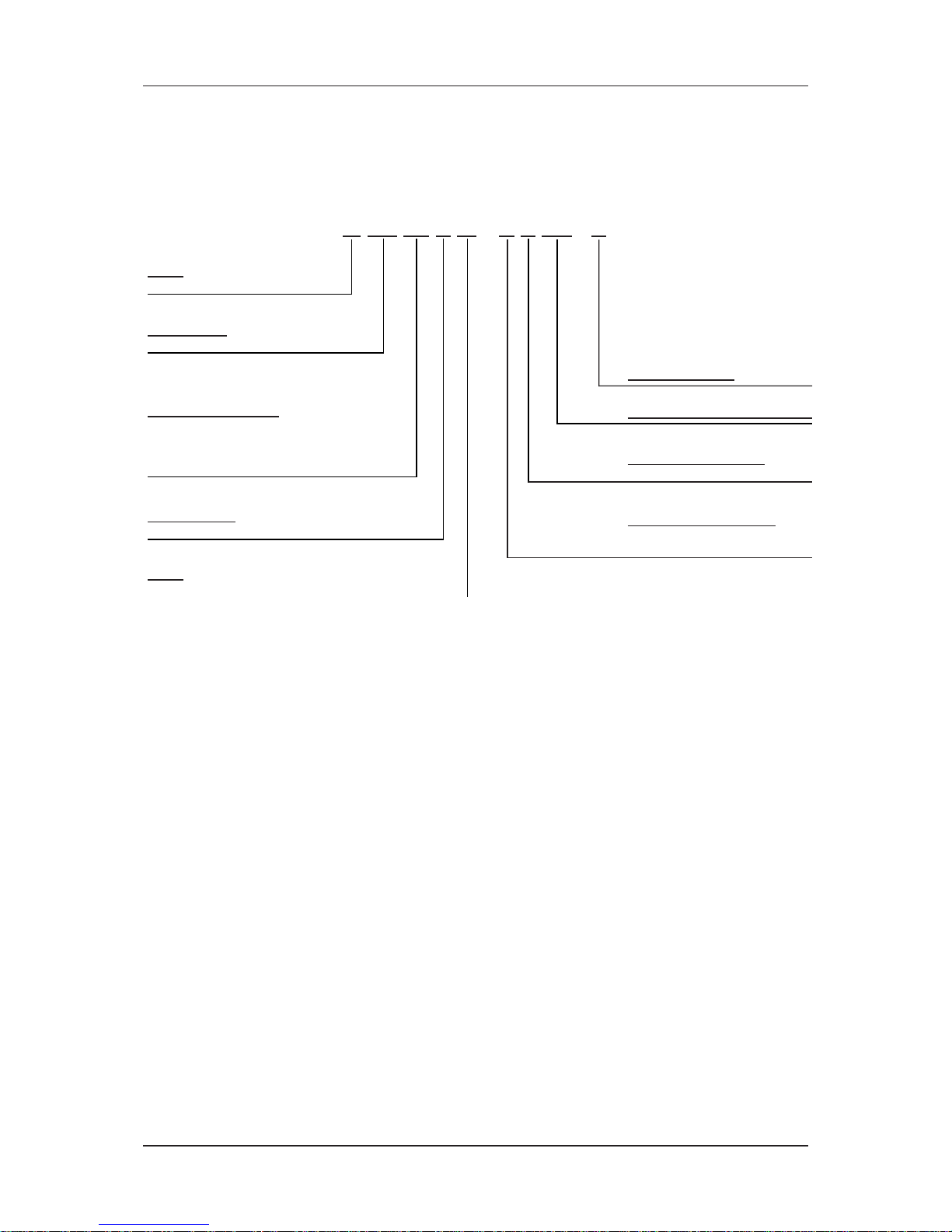
Nomenclature
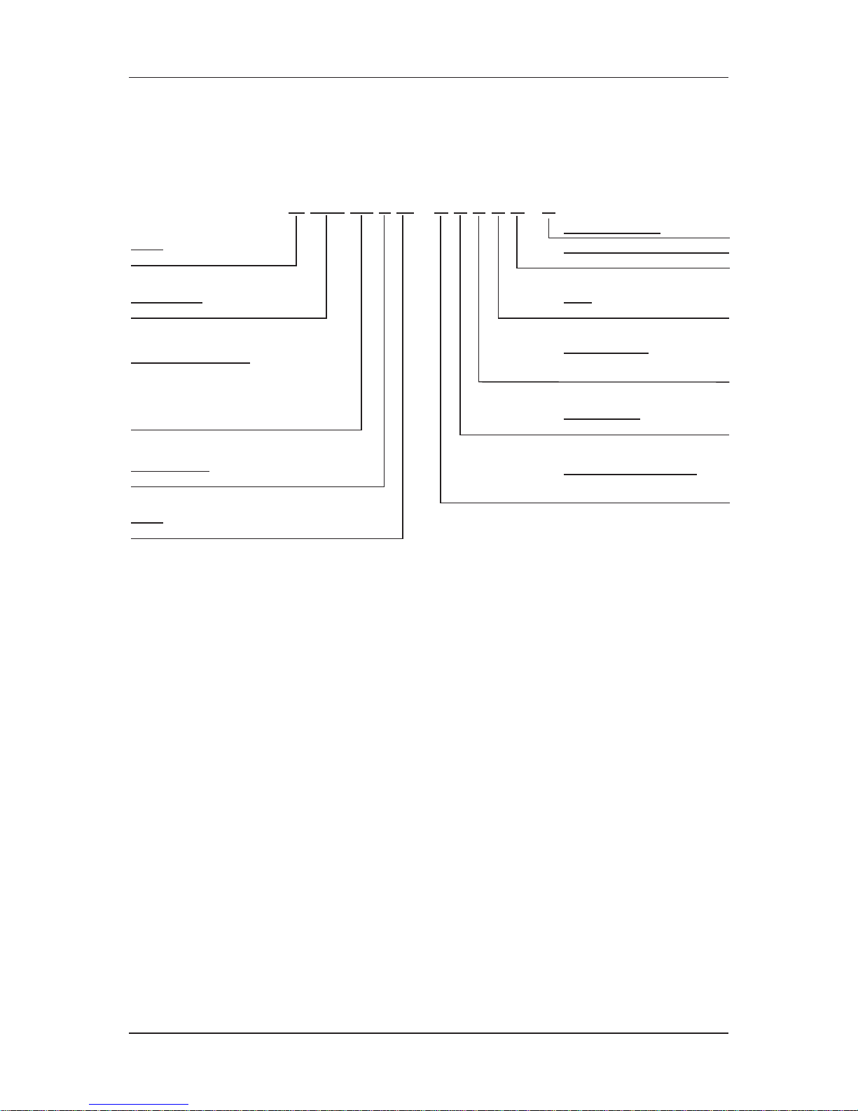
(Wall Mounted Fan Coil Unit)
M WM 10 L W – A C E D A - R
Brand
M : McQuay
Product Type
WM : Wall Mounted
Operating Mode
E : Cooling Only
H : Heatpump
Size (Cooling/Heating)
07 : 8,300/11,000 btu/hr
10 : 9,200/12,000 btu/hr
15 : 11,300/15,000 btu/hr
20 : 15,500/20,500 btu/hr
25 : 18,000/25,000 btu/hr
Product Series
L : L series
Product Specification Variation
A : First Issue
Grille
D : Grille D
Electrical Characteristics
A : 50Hz / 1Ph / 220-240V
K : 60Hz / 1Ph / 208-230V
Model
W : Chilled Water Fan Coil
Market Region
C : Export with CE Mark
RoHS Compliance
Page 5
Nomenclature
2
Nomenclature
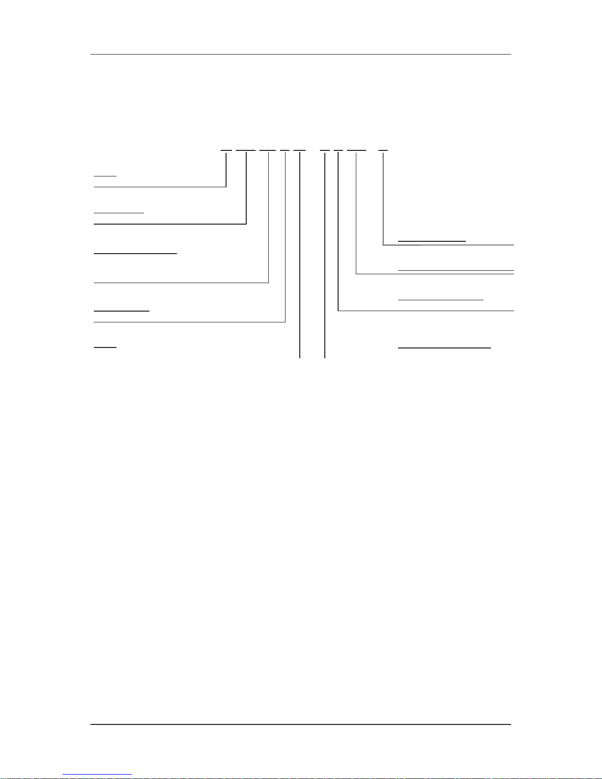
(Cassette Fan Coil Unit C series)
M CK 10 C W – A X AB - R
Brand
M : McQuay
Product Type
CK : Ceiling Cassette
Size (Cooling/Heating)
10 : 8,500/12,000 btu/hr
15 : 14,000/16,000 btu/hr
20 : 15,500/18,000 btu/hr
Product Series
C : C series
Electrical Characteristics
A : 50Hz / 1Ph / 220-240V
Model
W : Chilled Water Fan Coil
Type of ref. connection
X : Not applicable
RoHS Compliance
Product Specification Variation
Page 6
Nomenclature
3
Nomenclature
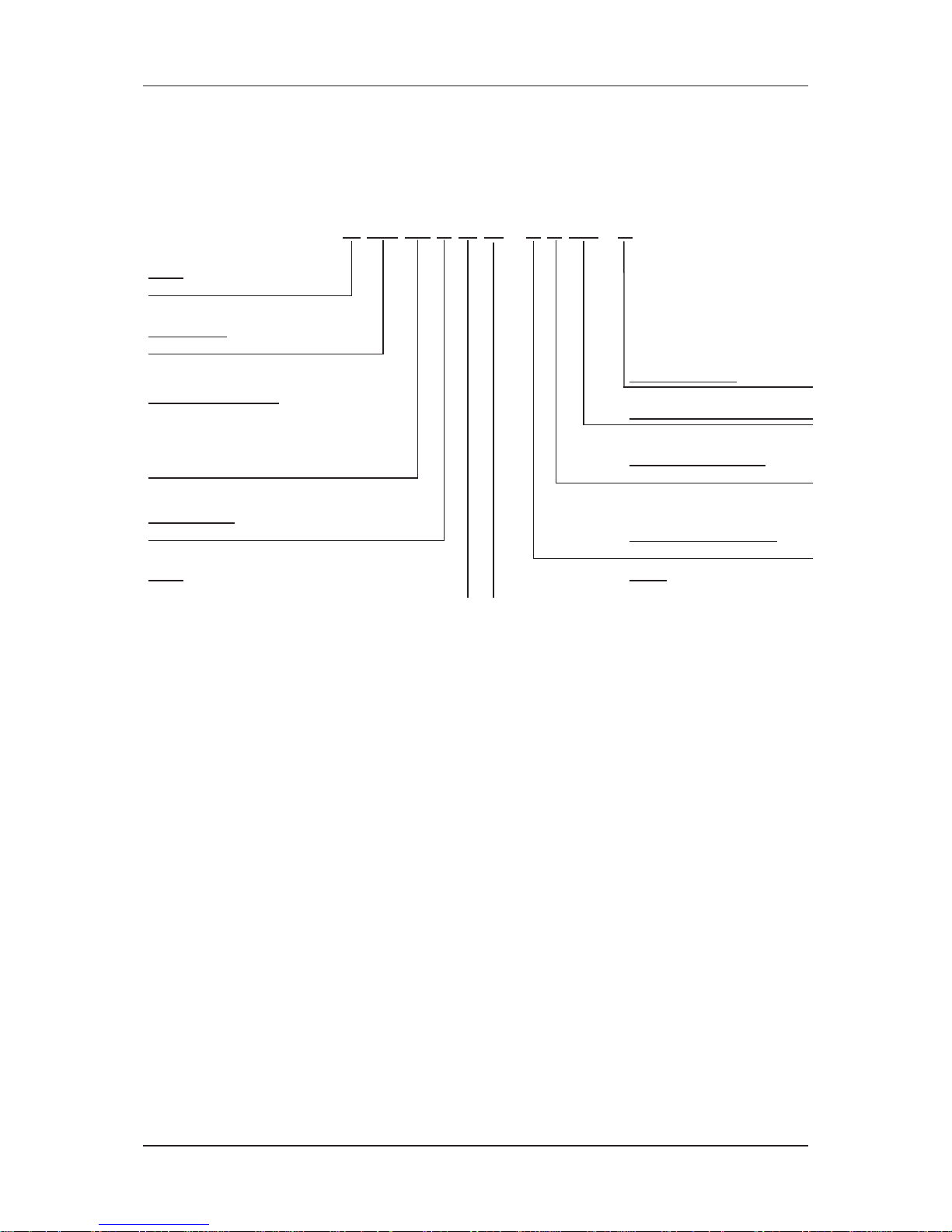
(Cassette Fan Coil Unit A series)
M CK 25 A W – A X AB - R
Brand
M : McQuay
Product Type
CK : Ceiling Cassette
Size (Cooling/Heating)
20 : 22,500 / 28,500 btu/hr
25 : 25,500 / 32,000 btu/hr
30 : 30,000 / 37,500 btu/hr
40 : 33,500 / 40,500 btu/hr
50 : 36,500 / 44,000 btu/hr
Product Series
A : A series
Electrical Characteristics
A : 50Hz / 1Ph / 220-240V
Model
W : Chilled Water Fan Coil
Type of ref. connection
X : Not applicable
RoHS Compliance
Product Specification Variation
Piping
H : 4 pipes system
Page 7
Nomenclature
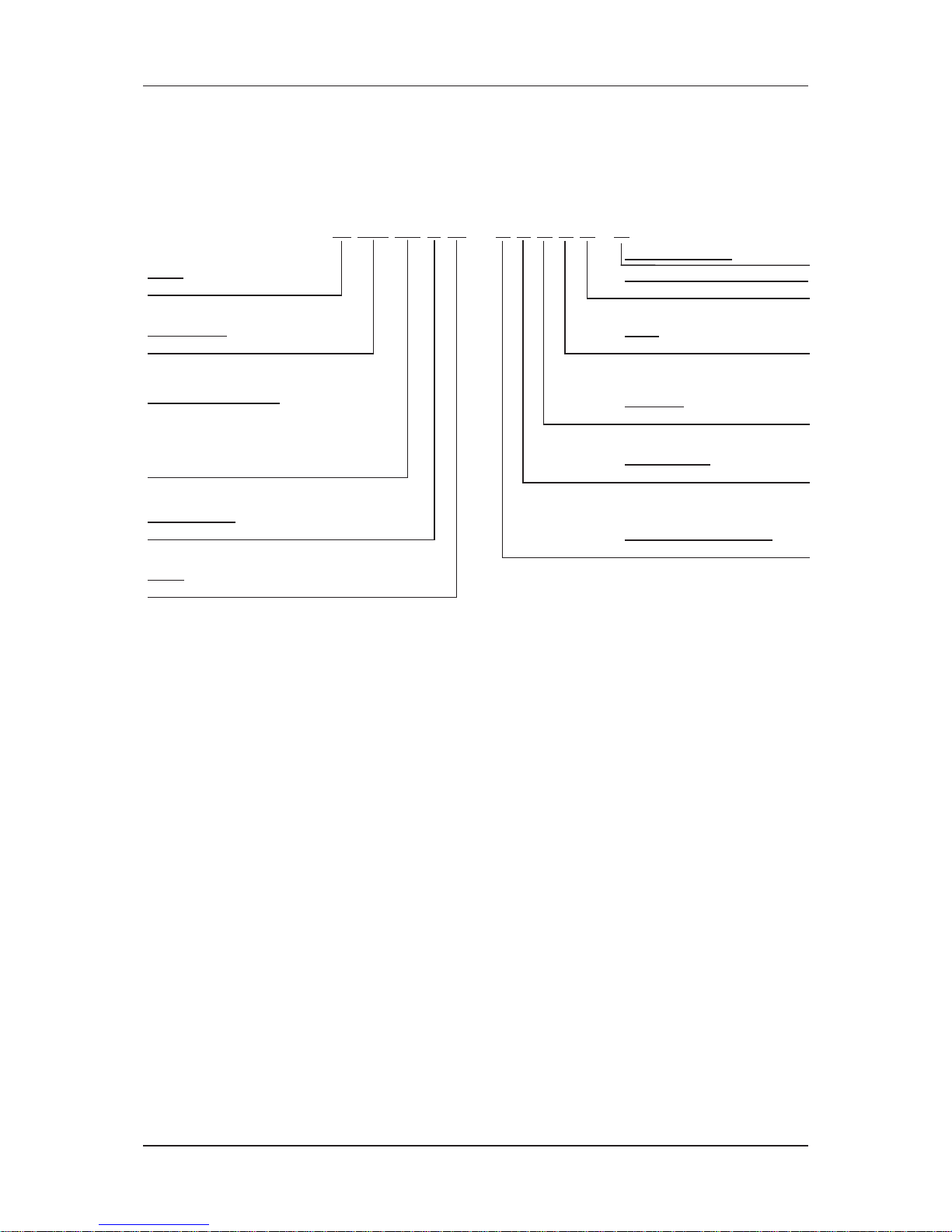
4
Nomenclature
(Ceiling Cassette E series)
M CK 20 E W – A E C A A - R
Brand
M : McQuay
Product Type
CK : Ceiling Cassette
Controller
C : W3 Control Module with DC swing
Size (Cooling/Heating)
20 : 20,000 / 28,000 btu/hr
25 : 25,000 / 33,600 btu/hr
30 : 30,000 / 38,300 btu/hr
40 : 38,000 / 45,500 btu/hr
50 : 43,000 / 52,000 btu/hr
Product Series
E : E series
Product Specification Variation
A : First Issue
Motor
A : AC motor
Electrical Characteristics
A : 50Hz / 1Ph / 220-240V
Model
W : Chilled Water Fan Coil
Market Region
E : Export w/o marking
RoHS Compliance
Page 8
Nomenclature
5
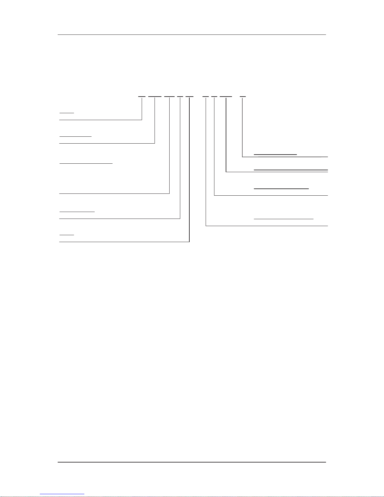
Nomenclature
(Ceiling Mounted D series)
M CM 25 D W – A X AB - R
Brand
M : McQuay
Product Type
CM : Ceiling Mounted
Size (Cooling/Heating)
20 : 17,000 / 22,000 btu/hr
25 : 20,800 / 25,900 btu/hr
30 : 24,600 / 28,000 btu/hr
40 : 31,200 / 42,300 btu/hr
50 : 45,000 / 51,500 btu/hr
Product Series
D : D series
Electrical Characteristics
A : 50Hz / 1Ph / 220-240V
Model
W : Chilled Water Fan Coil
Type of ref. connection
X : Not applicable
RoHS Compliance
Product Specification Variation
Page 9
Nomenclature
6
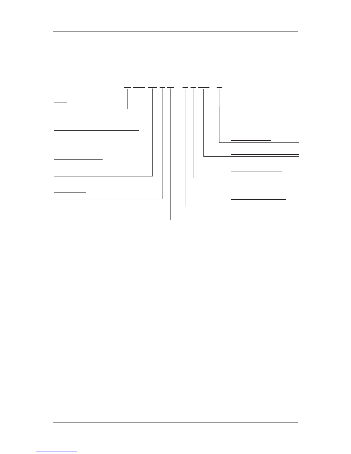
Nomenclature
(Ceiling Mounted E series)
M CM 15 E W – A X AB - R
Brand
M : McQuay
Product Type
CM : Ceiling Mounted
Size (Cooling/Heating)
10 : 15,500 / 19,500 btu/hr
15 : 20,300 / 25,000 btu/hr
20 : 21,000 / 28,000 btu/hr
Product Series
E : E series
Electrical Characteristics
A : 50Hz / 1Ph / 220-240V
Model
W : Chilled Water Fan Coil
Type of ref. connection
X : Not applicable
RoHS Compliance
Product Specification Variation
Page 10
Nomenclature
7
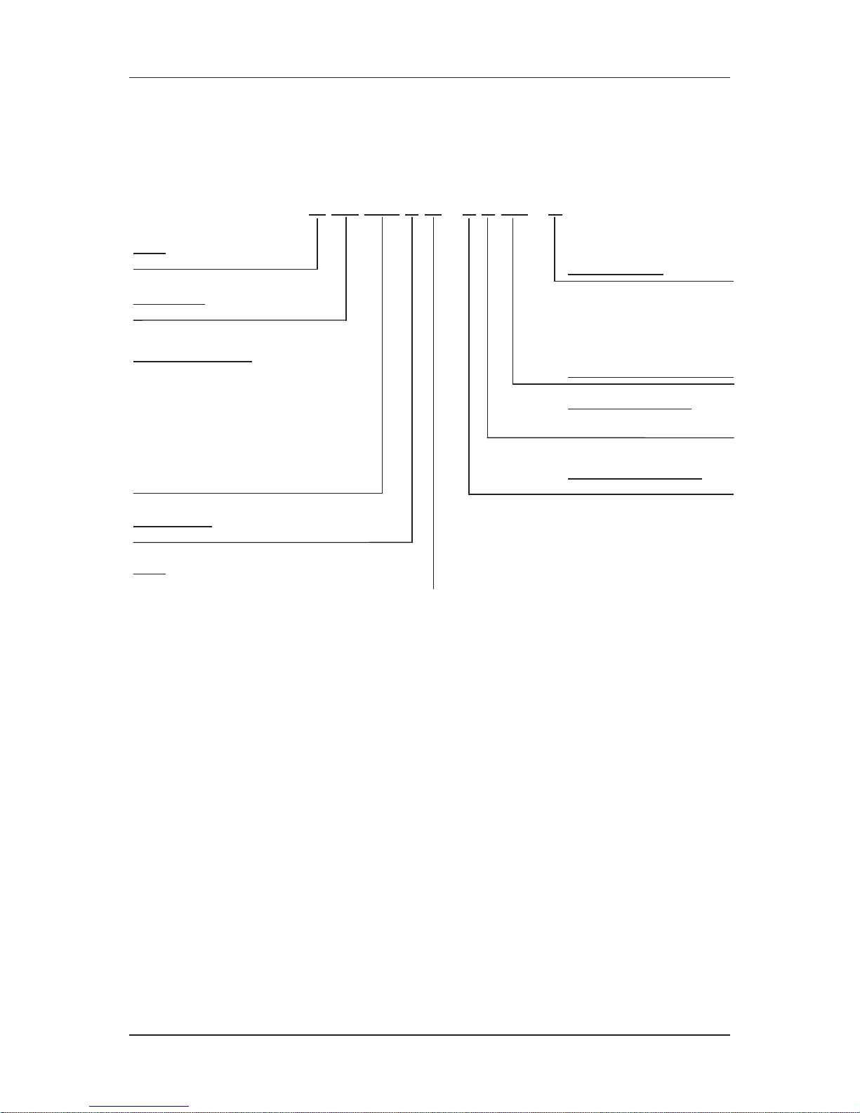
Nomenclature
(Ceiling Concealed)
CC 010 CM W – A X AC – R
RoHs Compliance
Brand
M : McQuay
Product Type
CC : Ceiling Concealed
Size (Cooling/Heating)
010 : 9,900/11,500 btu/hr
015 : 11,600/15,000 btu/hr
020 : 18,000/23,000 btu/hr
025 : 22,500/29,000 btu/hr
028 : 26,000/33,000 btu/hr
030 : 28,000/36,000 btu/hr
038 : 35,200/43,000 btu/hr
040 : 38,000/46,000 btu/hr
050 : 47,000/57,000 btu/hr
060 : 54,000/67,000 btu/hr
Type of ref. connection
X : Not applicable
F : For Flare
Product Series
C : C series
Electrical Characteristics
A : 50Hz / 1Ph / 220-240V
Model
W : Chilled Water Fan Coil
Product Specification Variation
Page 11
Nomenclature
8
Nomenclature
(Ducted Blower B series)
M DB 75 B W – A X AB - R
Size (Cooling/Heating)
75 : 75,600 / 78,000 btu/hr
100 : 95,000 / 97,500 btu/hr
125 : 125,000 / 138,000 btu/hr
150 : 150,000 / 170,000 btu/hr
Brand
M : McQuay
Product Type
DB : Ducted Blower
Product Series
B : B series
Electrical Characteristics
A : 50Hz / 1Ph / 220-240V
F : 50Hz / 3Ph / 380-415V
Model
W : Chilled Water Fan Coil
Type of ref. connection
X : Not applicable
RoHS Compliance
Product Specification Variation
Page 12
9
Application Information
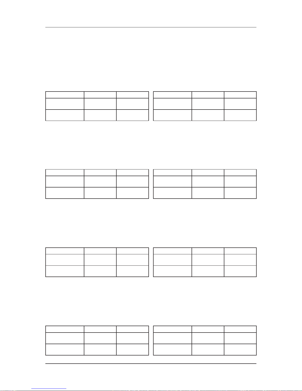
Application Information
Model: MWM Series
Operating Limits:
Thermal carrier : Water
Water temperature : 4°C ~ 10°C (Cooling), 35°C ~ 50°C (Heating)
Maximum water pressure : 16 bar
Air temperature : (as below)
Cooling Mode
Temperature Ts °C/°F Th °C/°F
Minimum indoor
temperature
19.0 / 66.2 14.0 / 57.2
Maximum indoor
temperature
32.0 / 89.6 23.0 / 73.4
Heating Mode
Temperature Ts °C/°F Th °C/°F
Minimum indoor
temperature
15.0 / 59.0 -
Maximum indoor
temperature
27.0 / 80.6 -
Ts: Dry bulb temperature. Th: Wet bulb temperature.
Model: MCK Series
Operating Limits:
Thermal carrier : Water
Water temperature : 4°C ~ 10°C (Cooling), 35°C ~ 50°C (2 Pipes), 35°C ~ 70°C (4 Pipes)
Maximum water pressure : 16 bar
Air temperature : (as below)
Cooling Mode
Temperature Ts °C/°F Th °C/°F
Minimum indoor
temperature
16.0 / 60.8 11.0 / 51.8
Maximum indoor
temperature
32.0 / 89.6 23.0 / 73.4
Heating Mode
Temperature Ts °C/°F Th °C/°F
Minimum indoor
temperature
16.0 / 60.8 -
Maximum indoor
temperature
30.0 / 86.0 -
Ts: Dry bulb temperature. Th: Wet bulb temperature.
Model: MCC Series
Operating Limits:
Thermal carrier : Water
Water temperature : 5 ~ 50°C
Maximum water pressure : 16 bar
Air temperature : (as below)
Cooling Mode
Temperature Ts °C/°F Th °C/°F
Minimum indoor
temperature
19.0 / 66.2 14.0 / 57.2
Maximum indoor
temperature
32.0 / 89.6 23.0 / 73.4
Heating Mode
Temperature Ts °C/°F Th °C/°F
Minimum indoor
temperature
15.0 / 59.0 -
Maximum indoor
temperature
27.0 / 80.6 -
Ts: Dry bulb temperature. Th: Wet bulb temperature.
Model: MDB Series
Operating Limits:
Thermal carrier : Water
Water temperature : 4°C ~ 10°C (Cooling), 35°C ~ 70°C (Heating)
Maximum water pressure : 16 bar
Air temperature : (as below)
Cooling Mode
Temperature Ts °C/°F Th °C/°F
Minimum indoor
temperature
19.0 / 66.2 14.0 / 57.2
Maximum indoor
temperature
32.0 / 89.6 23.0 / 73.4
Heating Mode
Temperature Ts °C/°F Th °C/°F
Minimum indoor
temperature
15.0 / 59.0 -
Maximum indoor
temperature
27.0 / 80.6 -
Ts: Dry bulb temperature. Th: Wet bulb temperature.
Page 13
10
Application Information
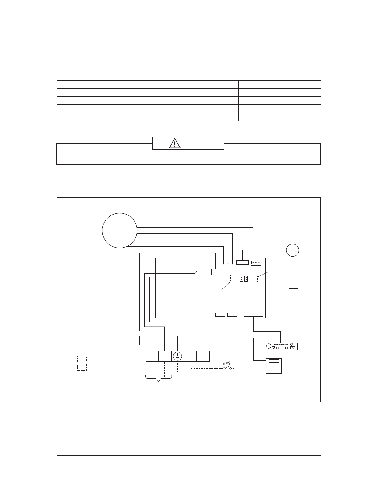
Installation Guide
System Confi guration
The standard controller board (W2/W3) comes with a VALVE jumper and a HEAT jumper. The system can be
confi gured as the jumper selection listed below:
HEAT Jumper VALVE Jumper
Heatpump Mode & Valve Application √√
Heatpump Mode & Valveless Application √ X
Cooling Mode & Valve Application X √
Cooling Mode & Valveless Application XX
√ Jumper Remained X Jumper Removed
Caution
Disconnect the power supply to the unit before attempting to connect the wiring
Valve, Heat and Fan Priority Setting
Model: MWM-LW Series
HEAT
VALV E
BLACK
N
CN_FAN
CN_PGRM CN_WIR CN_DSP
VALVE HEAT
VALV E
CN_STP
CN_ID COIL
CN_FAN FB
L
BLACK (LIVE)
RED (FAN CAP)
WHITE (NEUTRAL)
Valve Jumper
Heat Jumper
WHITE
BROWN
BLACK
BLUE
BLUE
RED
G/Y
NOTATION
FM : FAN MOTOR
AS : AIR SWING MOTOR
TH1 : INDOOR COIL THERMISTOR
TH2 : ROOM THERMISTOR
-WITH JUMPER FOR HEAT PUMP
-WITHOUT JUMPER FOR COOLING ONLY
-WITH JUMPER FOR VALVE APPLICATION
FIELD WIRING
-WITHOUT JUMPER FOR VALVELESS APPLICATION
2/3 WAY VALVE
L
POWER
SUPPLY
TH2
TH1
DISPLAY BOARD
WIRED
CONTROLLER
(OPTIONAL)
N
E
VALV E
N1 N L
AS
FM
Page 14
11
Application Information
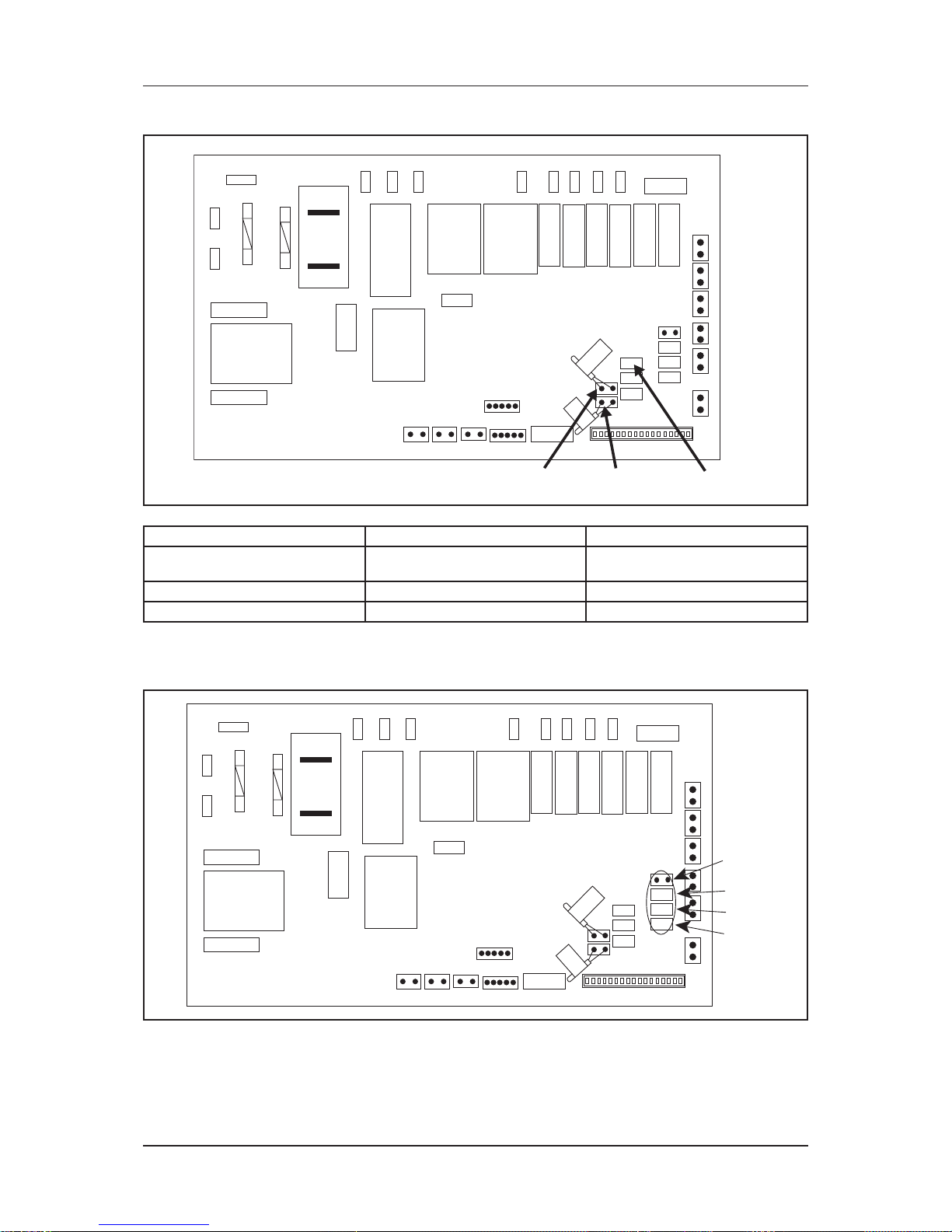
Model: MCK/MCC Series
HTR
L
Heat Jumper Fan Priority Jumper
N2
LIVE
N1
HI
MED
LOW
CN_TW
CN_PGRM
CN_WIR
ROOM
CN_STP
C_SENH_SEN
HEAT
VA LV E
CN_DSP
SHED
M4
M3
M2
M1
TFULL A_FRZ W_OPEN UNOCP
SLIENT
CVLV
HVLV
WTP
AS
CN_DRY
Valve Jumper
CO_DRAFT
Jumper With Jumper (Default) Without Jumper
Fan Priority Jumper
User set speed or lower fan if auto
mode is selected
Fan Stop when thermostat cat off
Heat Jumper For Heat pump For Cooling only
Valve Jumper For valve control For valveless control
MCK-AW/EW 4 pipes system controller board setting
A) Model selection
Model 1
Model 2
Model 3
Model 4
HTR
L
N2
LIVE
N1
HI
MED
LOW
CN_TW
CN_PGRM
CN_WIR
ROOM
CN_STP
C_SENH_SEN
HEAT
VA LV E
CN_DSP
SHED
M4
M3
M2
M1
TFULL A_FRZ W_OPEN UNOCP
SLIENT
CVLV
HVLV
WTP
AS
CN_DRY
CO_DRAFT
The standard controller board (W2.0/W3.0) comes with a default setting for model selection. Please select the model accordingly by using jumper.
Page 15
12
Application Information
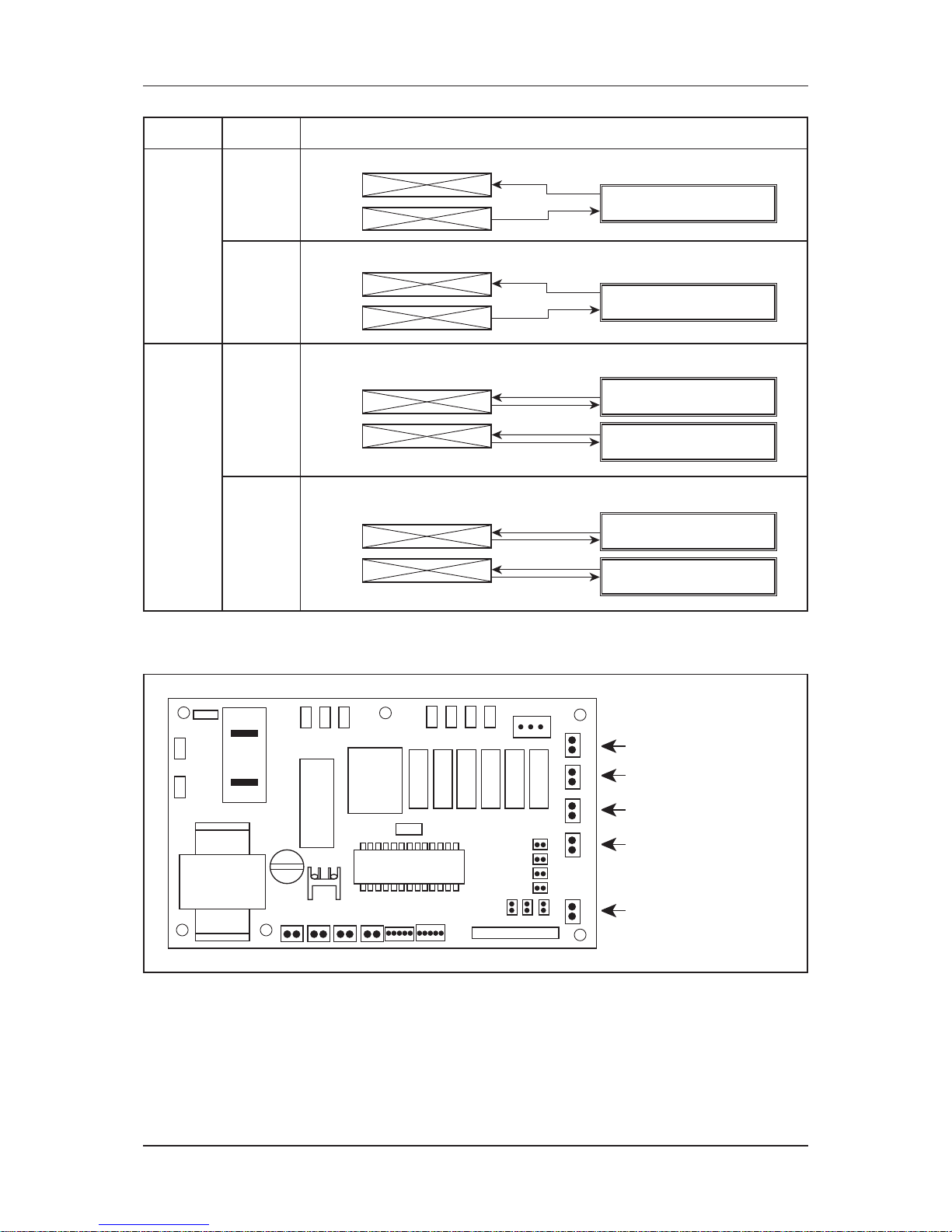
System Model Function
2 Pipe
System
4 Pipe
System
M1 Model 1
M2 Model 2
M3 Model 3
M4 Model 4
Cooling or Heating
Cooling or Heating with Auxiliary Heater
Cooling Only with Boiler
Cooling or Heating with Boiler
FCU
FCU
FCU
FCU
FCU
FCU
FCU
FCU
Mini Chiller (Cooling Only)
Mini Chiller (Cooling Only)
Boiler
Boiler
Mini Chiller (Cooling / Heating)
Mini Chiller (Cooling / Heating)
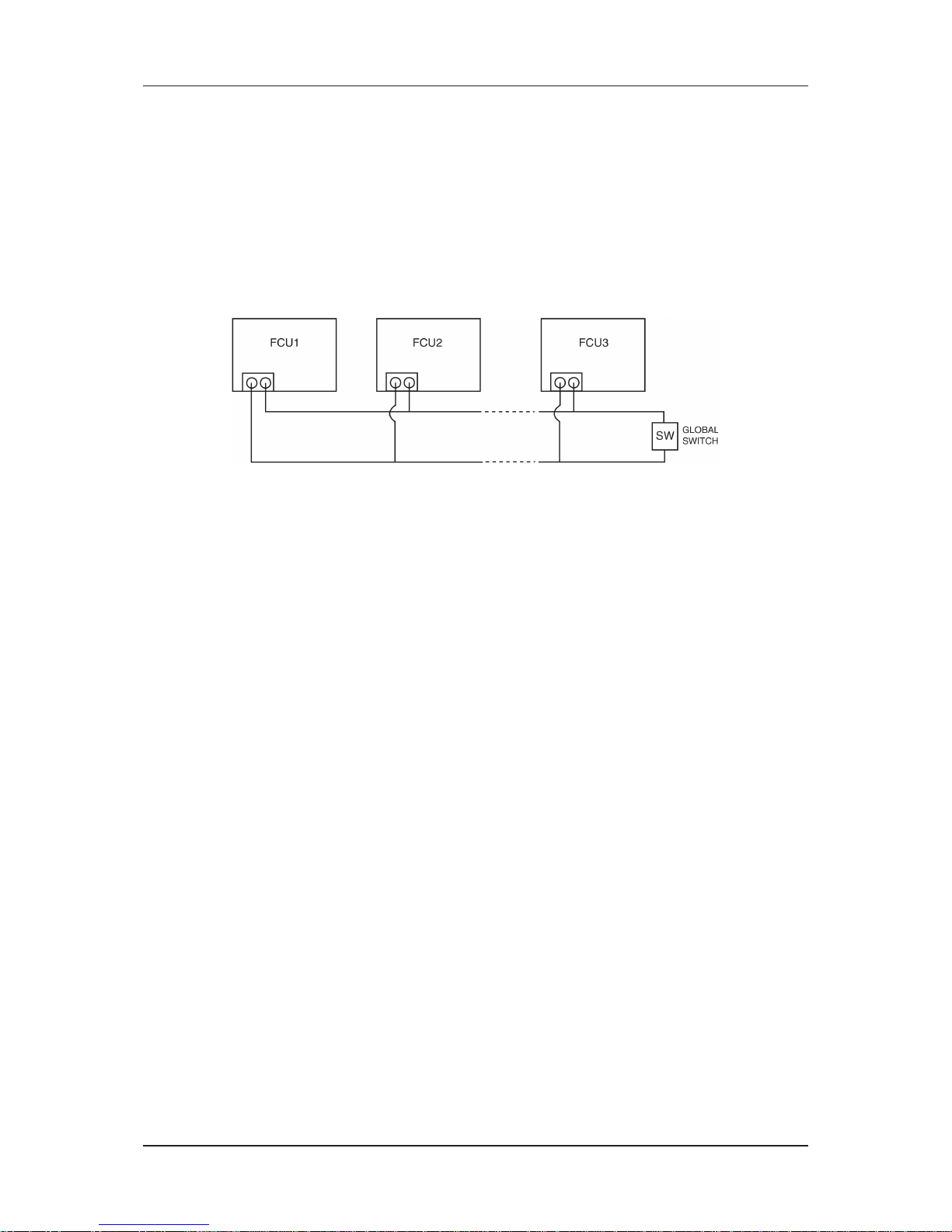
C) Others
The controller board comes with other option.
L
COMP
TRANSFORMER
UNOCP A_FRZ W_OPEN TFULL SHED
Unoccupied Mode
Anti Freeze Mode
Window Open Mode
Connect to Level Switch
Load Shedding Mode
i) Unoccupied Mode
If the dry contact is closed, the Unoccupied mode is activated and vice versa. When Timer On is active,
system goes back to Occupied mode.
The dry contact connection points can be connected parallel with other fan coil unit (FCU) boards. If the
dry contact is closed, Unoccupied mode will be activated on all fan coil units that are connected parallel as
shown in fi gure below.
Page 16
13
Application Information
ii) Anti Freeze Mode
Anti Freeze operation has the highest priority among all unit operation. Anti Freeze operation will be
activated only if dry contact is closed and vice versa.
iii) Window Open Mode
The dry contact connection points can be connected in parallel with other fan coil unit (FCU) boards. If the
dry contact is closed, Window open mode will be activated on all the fan coil units which are connected in
parallel as shown in fi gure below.
iv) Load Shedding
The dry contact connection points can be connected in parallel with other fan coil unit (FCU) boards. If the
dry contact is closed, Load shedding mode will be activated on all the fan coil units which are connected in
parallel as shown in fi gure below.
Global Unoccupied, Global Window Open and Global Load Shedding operation could also be activated via the
network communication bus line by master controller with or without the above connection.
NOTE :
i) Auto Fan Mode is only applicable in Model 3 only. (Cooling only with Boiler)
ii) Fan mode is not available in valveless control.
iii) Wired handset has an indoor room sensor. Avoid locating the wired handset at isolated places where room
temperature reading will be inaccurate.
Page 17
14
Application Information
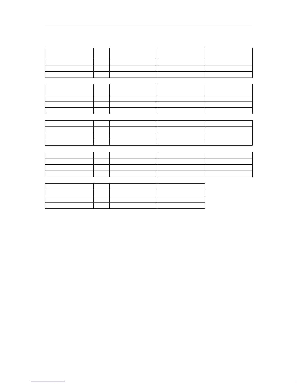
Cable Size
Model Unit MWM07/10/15/20/25LW MWM301W
MCK020/025/030/
040/050AW
Power supply cable size* mm² 1.5 2.5 1.5
Number of wire 3 3 3
Recommended fuse* A 2 20 2
Model Unit
MCK020/025/030/
040/050AWH
MCM020/025/
030/040/050DW
MCM015/020EW
Power supply cable size* mm² 1.5 1.5 2.5
Number of wire 3 3 3
Recommended fuse* A 2 2 2
Model Unit MCM025EW MCK10/15/20CW MCK20/25/30/40/50EW
Power supply cable size* mm² 4.0 1.5 1.5
Number of wire 3 3 3
Recommended fuse* A 2 2 2
Model Unit MCC10/15/20/25/28CW MCC30/38/40CW MCC50/60CW
Power supply cable size* mm² 1.5 1.5 1.5
Number of wire 3 3 3
Recommended fuse* A 5 10 16
Model Unit MDB75/100BW MDB125/150BW
Power supply cable size* mm² 1.5 1.5
Number of wire 3 4
Recommended fuse* A 5 5
Important: * These values are for information only. They should be checked and selected to comply local
or national codes and regulations. They are also subjected to the type of installation and size of
conductors.
Page 18
15
Sound Data
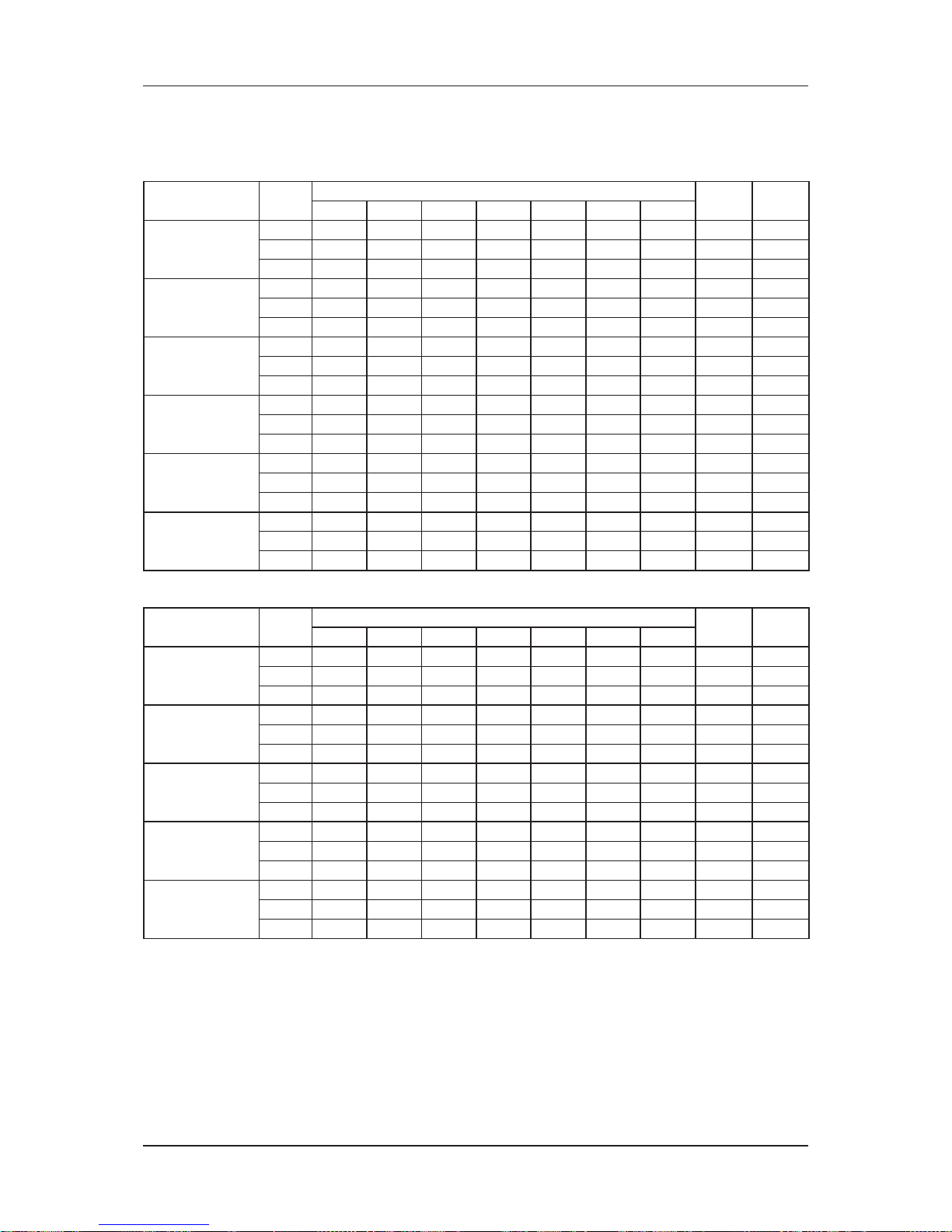
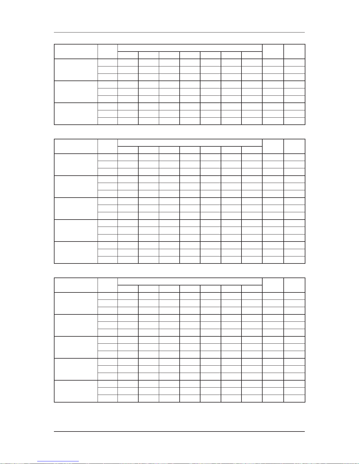
Sound Data
Sound Pressure Level
Model Speed
1/1 Octave A-Weighted Sound Pressure (dBA), ref 20μPa
Overall
(dBA)
Noise
Criteria
125Hz 250Hz 500Hz 1kHz 2kHz 4kHz 8kHz
MWM07LW
High 31 32 33 28 26 14 6 34 28
Med
25 29 28 24 19 9 5 29 22
Low 20 26 24 20 11 8 6 25 18
MWM10LW
High 30 33 33 32 28 17 8 35 31
Med
26 29 30 27 21 11 7 30 25
Low 19 25 25 21 14 6 6 25 19
MWM15LW
High 41 39 39 38 36 26 14 42 38
Med
38 36 37 34 32 22 10 39 33
Low 30 30 31 28 23 12 7 32 26
MWM20LW
High 37 38 38 39 33 22 11 42 38
Med
33 35 35 35 29 17 8 38 34
Low 29 33 32 31 23 12 7 34 30
MWM25LW
High 42 42 42 42 40 31 21 46 42
Med
37 38 39 38 34 24 13 42 37
Low 34 35 36 35 30 20 9 39 34
*MWM301W
High 42 46 45 44 41 35 28 49 43
Med
40 45 44 43 38 33 27 47 42
Low 37 43 43 40 35 30 26 45 39
Microphone position: 1m in front and 0.8m/*1m below the vertical centre line of the unit.
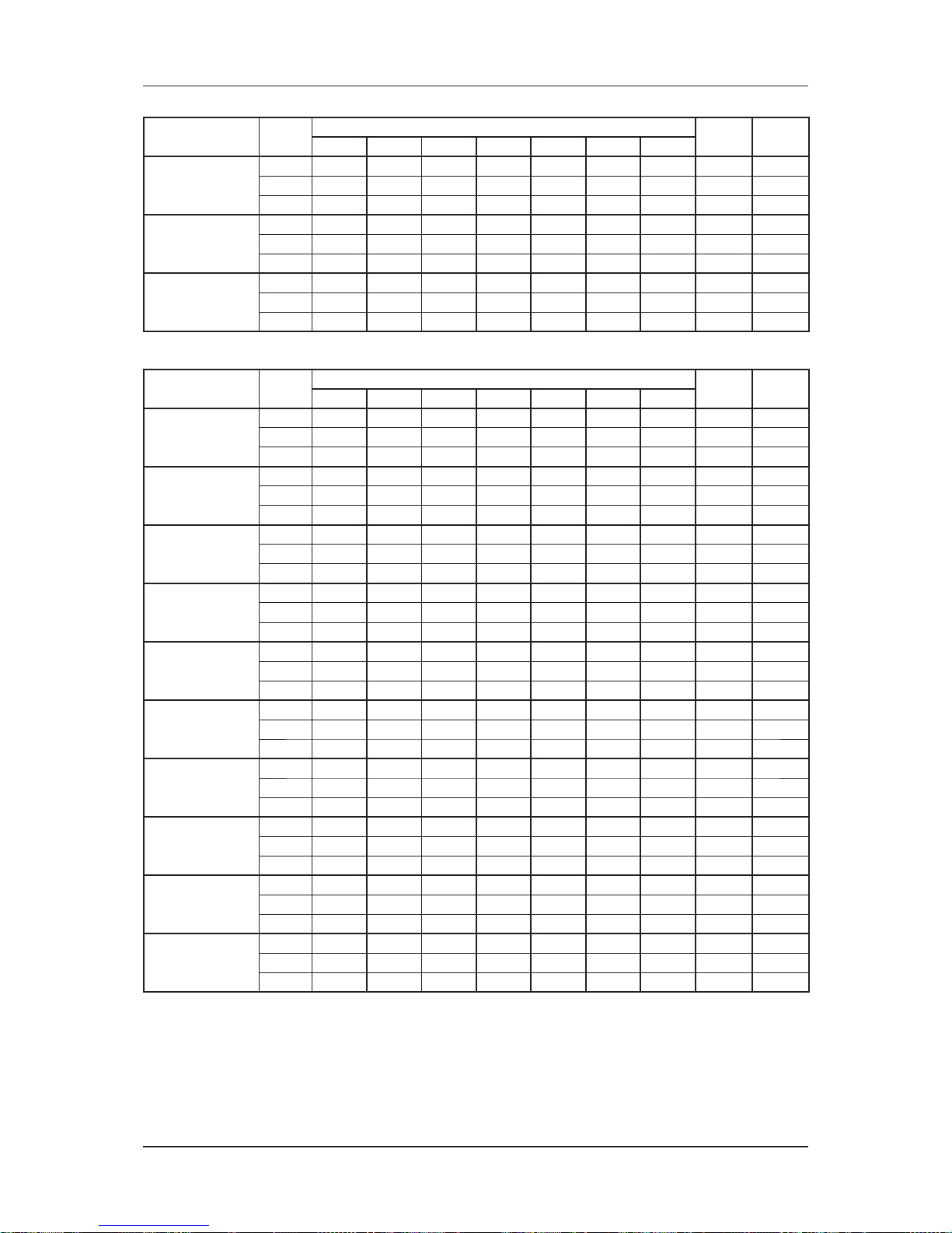
Model Speed
1/1 Octave A-Weighted Sound Pressure (dBA), ref 20μPa
Overall
(dBA)
Noise
Criteria
125Hz 250Hz 500Hz 1kHz 2kHz 4kHz 8kHz
MCK020AW/
AWH
High 46 45 40 38 32 21 14 42 37
Med
44 43 37 33 28 18 12 39 32
Low 43 42 35 31 26 17 11 37 31
MCK025AW/
AWH
High 48 46 43 39 33 27 19 45 38
Med
45 43 40 35 29 21 15 42 35
Low 43 42 38 32 27 19 14 40 33
*MCK030AW/
AWH
High 50 48 47 43 37 35 28 49 42
Med
48 45 43 38 32 31 27 45 38
Low 46 43 41 35 30 30 26 43 36
*MCK040AW/
AWH
High 50 49 49 46 39 38 31 51 45
Med
48 47 47 43 36 34 25 48 42
Low 46 45 46 41 34 30 23 46 41
*MCK050AW/
AWH
High 54 52 51 48 43 42 34 53 47
Med
52 50 50 46 41 40 32 52 46
Low 51 49 49 45 39 39 31 50 45
Microphone position: 1.4m/*1.5m below the face center of the air return of the unit.
Page 19
16
Sound Data
Model Speed
1/1 Octave A-Weighted Sound Pressure (dBA), ref 20μPa
Overall
(dBA)
Noise
Criteria
125Hz 250Hz 500Hz 1kHz 2kHz 4kHz 8kHz
MCK010CW
High
44 45 40 36 26 19 10 42 35
Med
40 38 34 28 19 9 7 35 29
Low
37 32 27 20 14 7 7 29 21
MCK015CW
High
48 48 44 39 31 27 15 45 39
Med
42 42 36 30 22 13 7 38 31
Low
39 36 28 20 15 6 6 30 23
MCK020CW
High
52 51 46 41 34 31 19 48 41
Med
44 43 39 33 26 18 8 40 33
Low
41 39 35 28 22 11 7 36 30
Microphone position: 1.4m below the face center of the air return of the unit.
Model Speed
1/1 Octave A-Weighted Sound Pressure (dBA), ref 20μPa
Overall
(dBA)
Noise
Criteria
125Hz 250Hz 500Hz 1kHz 2kHz 4kHz 8kHz
MCK020EW
High
44 43 42 35 29 23 15 42 37
Med
40 40 38 30 23 16 14 38 33
Low
35 34 32 23 15 10 14 32 26
MCK025EW
High
48 47 45 39 34 28 17 46 40
Med
44 42 42 34 28 21 10 42 37
Low
39 37 36 26 19 10 6 35 31
*MCK030EW
High
49 48 46 42 37 35 22 48 41
Med
44 44 42 36 32 27 14 43 37
Low
41 39 37 31 26 17 8 38 32
*MCK040EW
High
51 49 49 45 37 36 24 50 45
Med
48 46 47 40 33 31 18 47 43
Low
44 42 43 35 28 23 10 43 38
*MCK050EW
High
53 54 50 47 39 38 28 52 46
Med
49 48 47 43 36 35 25 49 43
Low
46 45 44 39 32 30 22 45 39
Microphone position: 1.4m/*1.5m below the face center of the air return of the unit.
Model Speed
1/1 Octave A-Weighted Sound Pressure (dBA), ref 20μPa
Overall
(dBA)
Noise
Criteria
125Hz 250Hz 500Hz 1kHz 2kHz 4kHz 8kHz
MCM020DW
High
45 46 47 46 41 38 29 50 45
Med
42 43 45 42 38 34 24 47 41
Low
36 37 39 35 31 24 15 40 34
MCM025DW
High
48 51 51 50 45 41 33 54 49
Med
47 50 50 49 44 40 32 53 48
Low
45 47 48 47 41 36 27 50 46
*MCM030DW
High
45 48 48 47 43 33 24 51 46
Med
44 47 47 46 42 32 23 50 45
Low
43 45 45 44 39 29 20 48 43
*MCM040DW
High
51 53 51 50 47 37 30 54 49
Med
48 51 50 49 46 36 28 53 48
Low
46 50 49 48 44 35 27 52 47
*MCM050DW
High
51 53 51 50 47 37 30 54 49
Med
48 51 50 49 46 36 28 53 48
Low
46 50 49 48 44 35 27 52 47
Microphone position: 1m in front of the unit and 0.8m/*1m below the air discharge opening.
Page 20
17
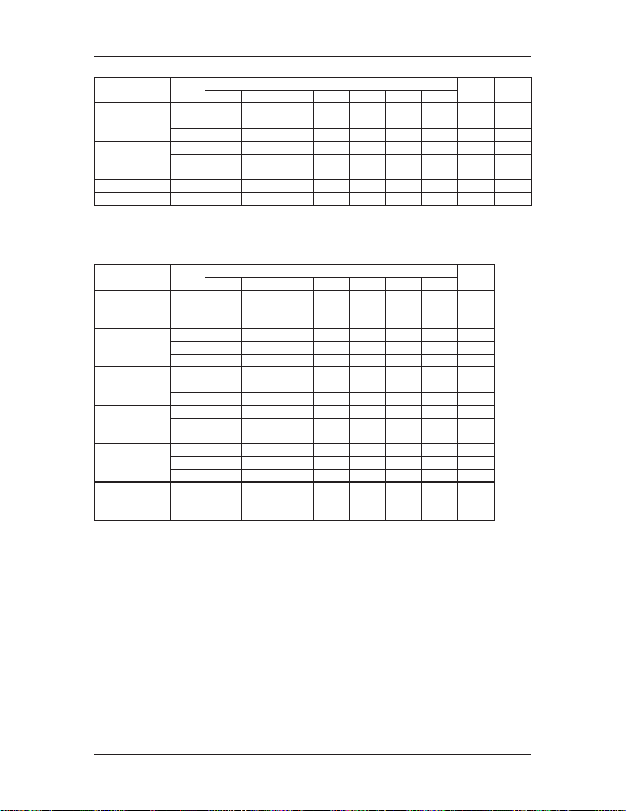
Sound Data
Model Speed
1/1 Octave A-Weighted Sound Pressure (dBA), ref 20μPa
Overall
(dBA)
Noise
Criteria
125Hz 250Hz 500Hz 1kHz 2kHz 4kHz 8kHz
MCM15EW
High 42 46 49 44 43 36 31 50 45
Med
36 40 43 37 36 27 20 43 38
Low 34 38 41 34 33 23 15 41 36
MCM20EW
High 45 47 51 48 47 40 34 53 48
Med
43 46 49 46 44 37 31 51 45
Low 42 46 47 44 42 35 27 49 43
MCM25EW
High 47 50 53 50 50 43 39 56 51
Med
44 46 49 46 45 38 33 51 46
Low 38 40 43 38 37 28 22 44 38
Microphone position: 1m in front of the unit and 1m below the air discharge opening.
Model Speed
1/1 Octave A-Weighted Sound Pressure (dBA), ref 20μPa
Overall
(dBA)
Noise
Criteria
125Hz 250Hz 500Hz 1kHz 2kHz 4kHz 8kHz
MCC010CW
High 43 35 35 30 26 18 13 36 30
Med
43 34 34 28 25 17 12 35 29
Low 42 31 31 27 22 14 9 33 25
MCC015CW
High 46 40 40 33 29 21 17 40 35
Med
45 38 38 31 27 18 14 38 33
Low 40 33 33 26 21 11 9 33 28
MCC020CW
High 47 41 43 35 31 24 19 42 38
Med
47 41 41 34 31 23 18 41 36
Low 47 39 39 33 29 21 16 40 34
MCC025CW
High 48 41 40 35 31 24 19 41 35
Med
47 39 39 34 29 22 17 40 34
Low 44 35 35 30 25 17 12 36 30
MCC028CW
High 45 42 39 35 31 26 22 41 34
Med
42 38 37 32 28 22 17 38 32
Low 36 33 33 27 23 16 11 34 27
MCC030CW
High 50 45 43 42 37 31 26 46 41
Med
45 40 40 38 32 26 20 42 37
Low 42 36 37 33 28 22 15 38 32
MCC038CW
High 54 51 48 46 41 36 31 51 45
Med
51 48 46 45 37 32 26 48 44
Low 47 45 44 41 34 28 22 45 40
MCC040CW
High 54 47 47 45 39 35 29 49 44
Med
49 42 43 41 35 31 24 45 40
Low 45 39 41 37 30 26 18 41 36
MCC050CW
High 54 49 49 48 43 37 32 52 47
Med
53 47 46 47 40 35 29 50 46
Low 51 45 44 44 36 32 26 47 43
MCC060CW
High 55 49 49 50 44 37 33 53 49
Med
53 46 47 47 39 34 28 50 46
Low 51 43 44 43 35 30 24 47 42
Microphone position: 1.5m below the centre of the unit.
(Tested with 2m length duct at the air discharge outlet and air return inlet)
Page 21
18
Sound Data
Model Speed
1/1 Octave A-Weighted Sound Pressure (dBA), ref 20μPa
Overall
(dBA)
Noise
Criteria
125Hz 250Hz 500Hz 1kHz 2kHz 4kHz 8kHz
MDB075BW
High 57 50 47 44 40 35 24 50 43
Med
57 46 44 40 35 30 17 46 41
Low 48 42 41 35 30 24 6 42 36
MDB100BW
High 57 53 50 50 44 40 31 54 49
Med
55 51 49 48 42 38 28 52 47
Low 54 50 48 46 40 35 25 50 45
MBD125BW High 57 55 56 53 51 46 38 58 53
MDB150BW High 57 55 56 53 51 46 38 58 53
Microphone position: 1m in front of the unit and center of the unit.
1m away from every side of the unit and 1m above fl oor level.
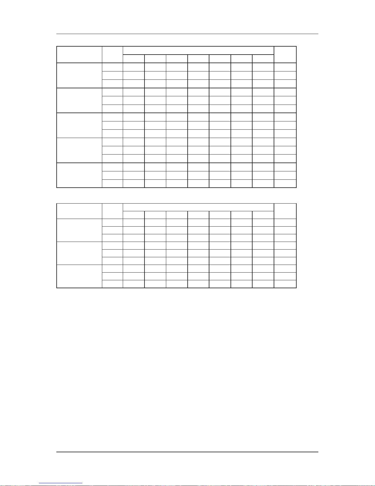
Sound Power Level
Model Speed
1/1 Octave Sound Power Level (dB, reference 1pW)
Overall
A (dBA)
125Hz 250Hz 500Hz 1kHz 2kHz 4kHz 8kHz
MWM07LW
High 40 43 44 41 36 23 19 45
Med
39 40 40 37 29 20 28 41
Low 38 37 35 32 21 16 23 36
MWM10LW
High 48 45 46 44 38 28 20 48
Med
48 41 42 40 32 18 19 44
Low 45 37 38 35 24 14 18 39
MWM15LW
High 48 50 52 51 46 38 26 55
Med
45 47 49 47 41 32 22 50
Low 43 42 44 41 34 22 18 45
MWM20LW
High 50 51 53 51 42 33 20 55
Med
47 49 50 48 38 27 17 51
Low 45 46 47 44 33 22 17 47
MWM25LW
High 53 55 55 55 50 40 26 59
Med
48 51 52 50 42 33 21 54
Low 45 48 50 47 38 29 18 51
MWM301W
High 50 55 62 59 54 43 32 64
Med
50 53 61 57 51 41 30 61
Low 48 51 58 54 48 37 24 58
Measured In Reverberation Chamber
Page 22
19
Sound Data
Model Speed
1/1 Octave Sound Power Level (dB, reference 1pW)
Overall
A (dBA)
125Hz 250Hz 500Hz 1kHz 2kHz 4kHz 8kHz
MCK020AW/
AWH
High 59 57 50 46 42 32 28 52
Med
58 56 47 43 38 31 27 50
Low 57 55 46 42 36 30 26 49
MCK025AW/
AWH
High 60 58 52 49 43 37 31 55
Med
57 55 49 45 39 33 28 52
Low 55 53 47 42 37 32 27 50
MCK030AW/
AWH
High 64 62 57 54 47 35 40 60
Med
60 58 54 49 42 41 39 56
Low 59 57 52 47 40 39 37 54
MCK040AW/
AWH
High 64 62 60 56 49 46 37 61
Med
62 60 58 53 46 42 34 59
Low 61 59 57 51 44 38 33 57
MCK050AW/
AWH
High 67 65 63 59 53 52 44 64
Med
66 64 61 57 51 51 42 63
Low 65 63 60 56 49 49 41 61
Measured In Reverberation Chamber
Model Speed
1/1 Octave Sound Power Level (dB, reference 1pW)
Overall
A (dBA)
125Hz 250Hz 500Hz 1kHz 2kHz 4kHz 8kHz
MCK010CW
High 53 56 49 43 35 28 21 52
Med
47 49 42 35 26 20 19 45
Low 43 44 36 27 19 14 19 39
MCK015CW
High 56 58 55 50 42 38 29 56
Med
50 51 48 41 32 26 20 49
Low 47 49 45 37 27 20 19 45
MCK020CW
High 56 58 55 50 42 38 29 56
Med
50 51 48 41 32 26 20 49
Low 47 49 45 37 27 20 19 45
Measured In Reverberation Chamber
Page 23
20
Sound Data
Model Speed
1/1 Octave Sound Power Level (dB, reference 1pW)
Overall
A (dBA)
125Hz 250Hz 500Hz 1kHz 2kHz 4kHz 8kHz
MCK020EW
High 53 54 52 45 35 31 19 52
Med
50 51 48 39 29 23 17 47
Low 46 45 42 32 22 14 17 41
MCK025EW
High 58 58 55 48 39 37 25 55
Med
53 53 51 43 33 29 18 51
Low 49 48 45 36 28 21 17 45
*MCK030EW
High 59 61 56 51 43 44 31 58
Med
54 55 52 46 38 36 23 53
Low 50 50 47 40 32 26 17 47
*MCK040EW
High 60 60 58 54 45 45 33 59
Med
57 57 56 50 41 40 26 56
Low 53 53 51 44 35 32 19 51
*MCK050EW
High 64 66 61 55 48 48 37 62
Med
59 60 57 52 44 44 32 58
Low 56 56 54 48 40 38 25 55
Measured In Reverberation Chamber
Model Speed
1/1 Octave Sound Power Level (dB, reference 1pW)
Overall
A (dBA)
125Hz 250Hz 500Hz 1kHz 2kHz 4kHz 8kHz
MCM020DW
High 58 62 58 56 52 47 39 61
Med
56 60 57 54 50 44 35 59
Low 52 55 51 48 43 34 28 53
MCM025DW
High 64 68 64 63 57 54 47 67
Med
63 67 63 62 56 53 46 66
Low 61 64 61 60 53 49 41 63
MCM030DW
High 62 65 62 60 54 46 38 64
Med
61 64 61 59 53 456 37 63
Low 58 62 59 57 51 42 34 61
MCM040DW
High 67 70 64 63 59 50 44 67
Med
64 68 63 62 58 49 42 66
Low 62 67 62 61 56 48 41 65
MCM050DW
High 67 70 64 63 59 50 44 67
Med
64 68 63 62 58 49 42 66
Low 62 67 62 61 56 48 41 65
Measured In Reverberation Chamber
Model Speed
1/1 Octave Sound Power Level (dB, reference 1pW)
Overall
A (dBA)
125Hz 250Hz 500Hz 1kHz 2kHz 4kHz 8kHz
MCM15EW
High 26 37 45 44 44 37 30 50
Med
20 31 40 37 37 28 19 43
Low 18 29 37 34 34 24 14 41
MCM20EW
High N/A N/A N/A N/A N/A N/A N/A 53
Med
N/A N/A N/A N/A N/A N/A N/A 51
Low N/A N/A N/A N/A N/A N/A N/A 49
MCM25EW
High 31 42 50 50 51 44 38 56
Med
28 37 46 46 46 39 32 51
Low 22 32 40 38 38 29 20 44
Measured In Reverberation Chamber
Page 24
21
Sound Data
Model Speed
1/1 Octave Sound Power Level (dB, reference 1pW)
Overall
A (dBA)
125Hz 250Hz 500Hz 1kHz 2kHz 4kHz 8kHz
MCC010CW
High 57 54 52 52 51 46 44 57
Med
54 51 50 49 48 43 39 54
Low 51 48 47 46 44 39 35 51
MCC015CW
High 60 58 57 56 54 48 44 61
Med
56 55 54 53 50 44 40 58
Low 51 50 49 48 44 37 34 52
MCC020CW
High 63 62 61 61 59 55 51 65
Med
61 61 59 60 58 53 49 64
Low 57 56 56 56 53 48 44 60
MCC025CW
High 63 62 61 62 59 56 53 66
Med
61 60 59 60 57 53 50 64
Low 58 57 56 57 54 49 47 61
MCC028CW
High 59 61 58 61 57 54 52 64
Med
56 57 55 57 54 50 48 61
Low 52 53 51 53 50 45 41 57
MCC030CW
High 65 66 68 69 65 63 60 73
Med
61 62 64 65 61 58 55 69
Low 56 58 60 61 57 53 49 64
MCC038CW
High 70 70 71 72 68 66 64 76
Med
67 67 68 70 65 62 60 73
Low 65 64 65 66 61 58 56 70
MCC040CW
High 65 68 70 72 68 66 64 76
Med
65 65 67 68 64 62 59 72
Low 59 61 63 64 60 59 54 68
MCC050CW
High 67 69 71 72 69 66 64 76
Med
66 66 69 69 66 63 61 73
Low 63 64 66 67 62 60 57 70
MCC060CW
High 69 70 72 74 71 69 68 78
Med
69 68 70 71 67 65 63 75
Low 64 65 67 67 63 61 59 71
Measured In Reverberation Chamber
Model Speed
1/1 Octave Sound Power Level (dB, reference 1pW)
Overall
A (dBA)
125Hz 250Hz 500Hz 1kHz 2kHz 4kHz 8kHz
MDB075BW
High 68 67 72 70 65 65 57 74
Med
64 64 68 65 61 59 51 69
Low 61 60 63 60 56 53 43 65
MDB100BW
High
71 71 74 74 70 70 63 78
Med
70 69 73 72 68 68 60 76
Low 67 67 71 69 65 64 56 73
MDB125BW High 75 76 75 72 69 65 60 77
MDB150BW High 75 76 75 72 69 65 60 77
Measured In Reverberation Chamber
Page 25
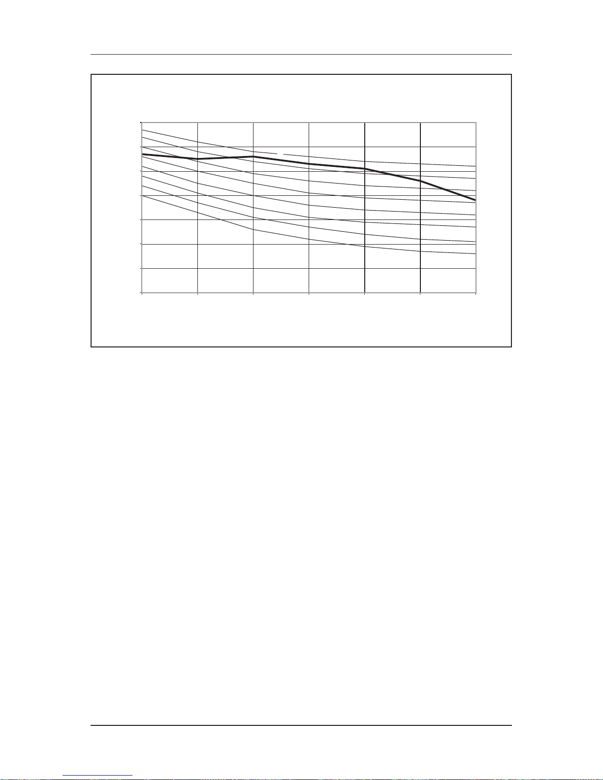
22
Sound Data
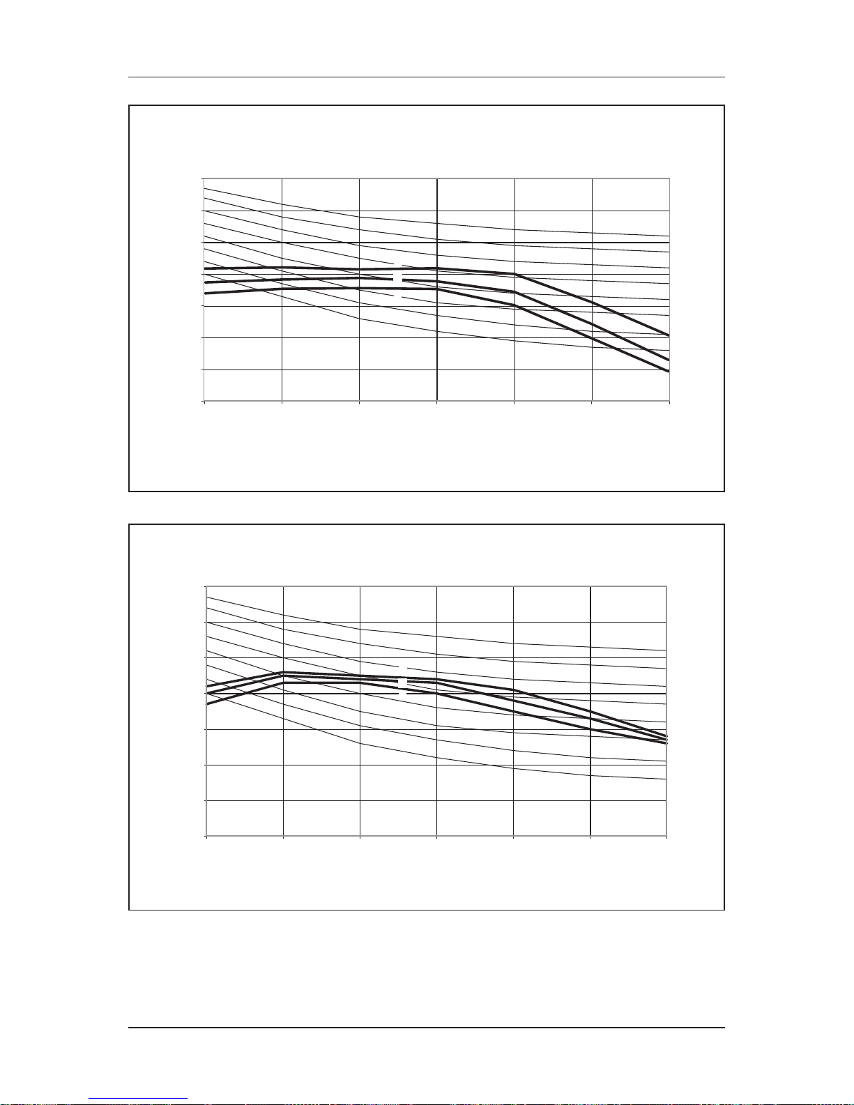
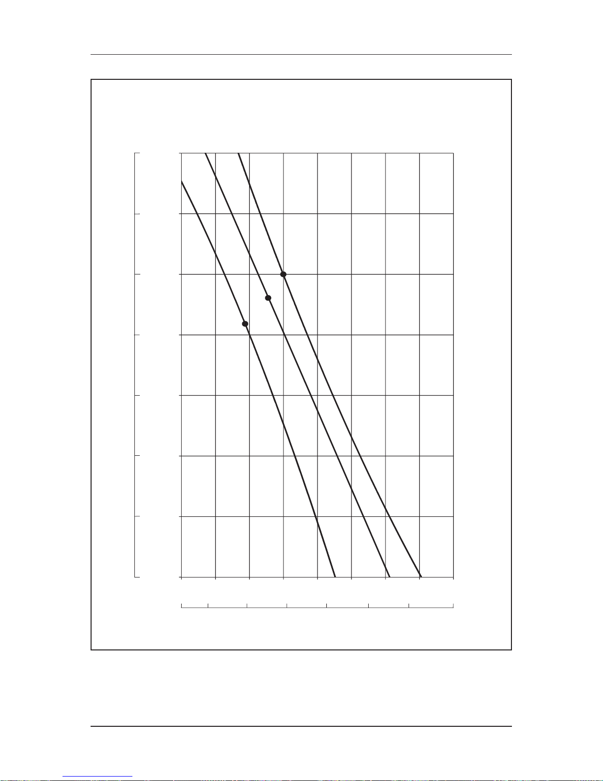
NC Curve
MWM07LW
0
10
20
30
40
50
60
70
125 250 500 1000 2000 4000 8000
Octave-band frequency (Hz)
Sound pressure level (dB, ref 20μPa)
NC-20
NC-30
NC-25
NC-35
NC-40
NC-45
NC-50
NC-55
H
M
L
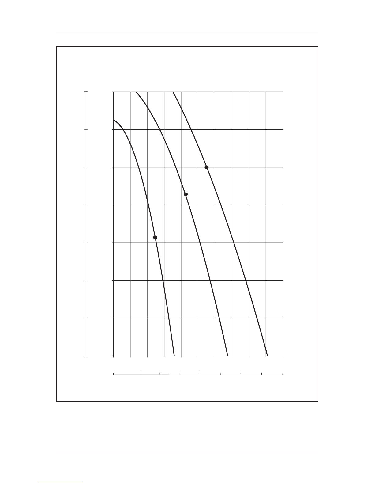
MWM010LW
0
10
20
30
40
50
60
70
125 250 500 1000 2000 4000 8000
Octave-band frequency (Hz)
Sound pressure level (dB, ref 20PPa)
NC-20
NC-30
NC-25
NC-35
NC-40
NC-45
NC-50
NC-55
H
M
L
Page 26
23
Sound Data
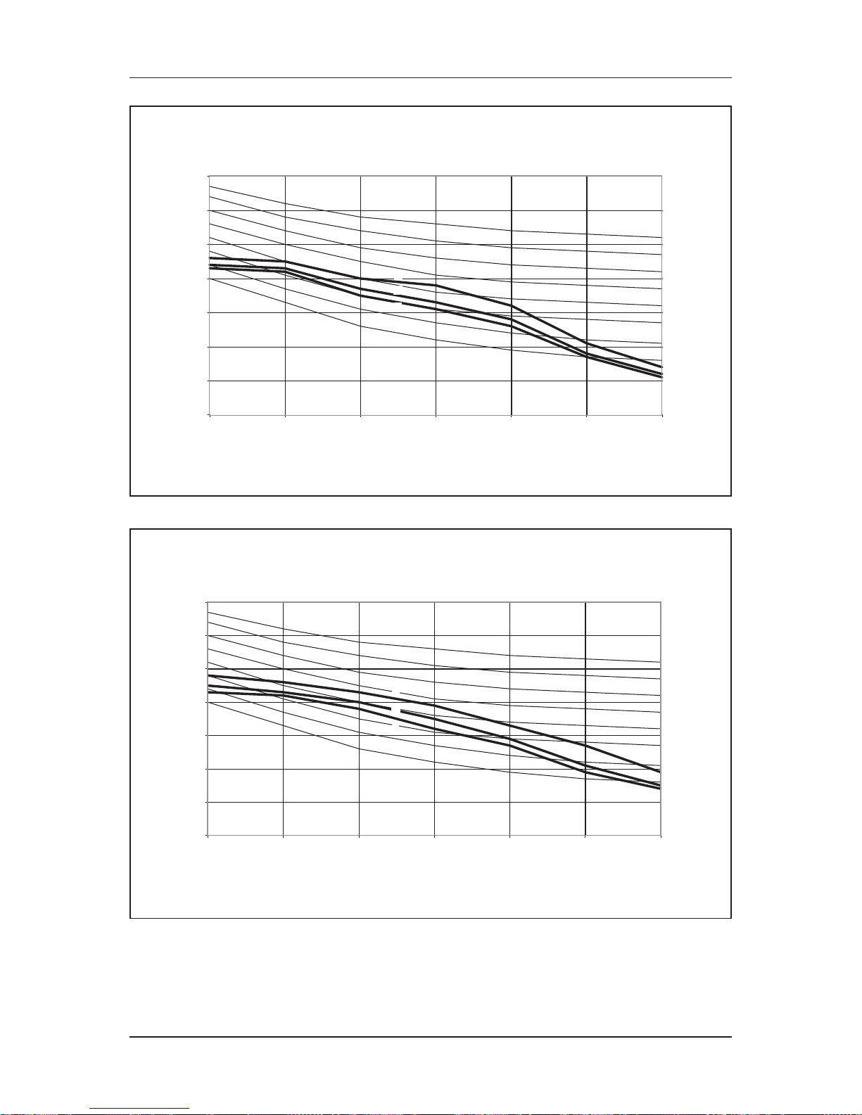
MWM15LW
0
10
20
30
40
50
60
70
125 250 500 1000 2000 4000 8000
Octave-band frequency (Hz)
Sound pressure level (dB, ref 20PPa)
NC-20
NC-30
NC-25
NC-35
NC-40
NC-45
NC-50
NC-55
H
M
L
MWM20LW
0
10
20
30
40
50
60
70
125 250 500 1000 2000 4000 8000
Octave-band frequency (Hz)
Sound pressure level (dB, ref 20μPa)
NC-20
NC-30
NC-25
NC-35
NC-40
NC-45
NC-50
NC-55
H
M
L
Page 27
24
Sound Data
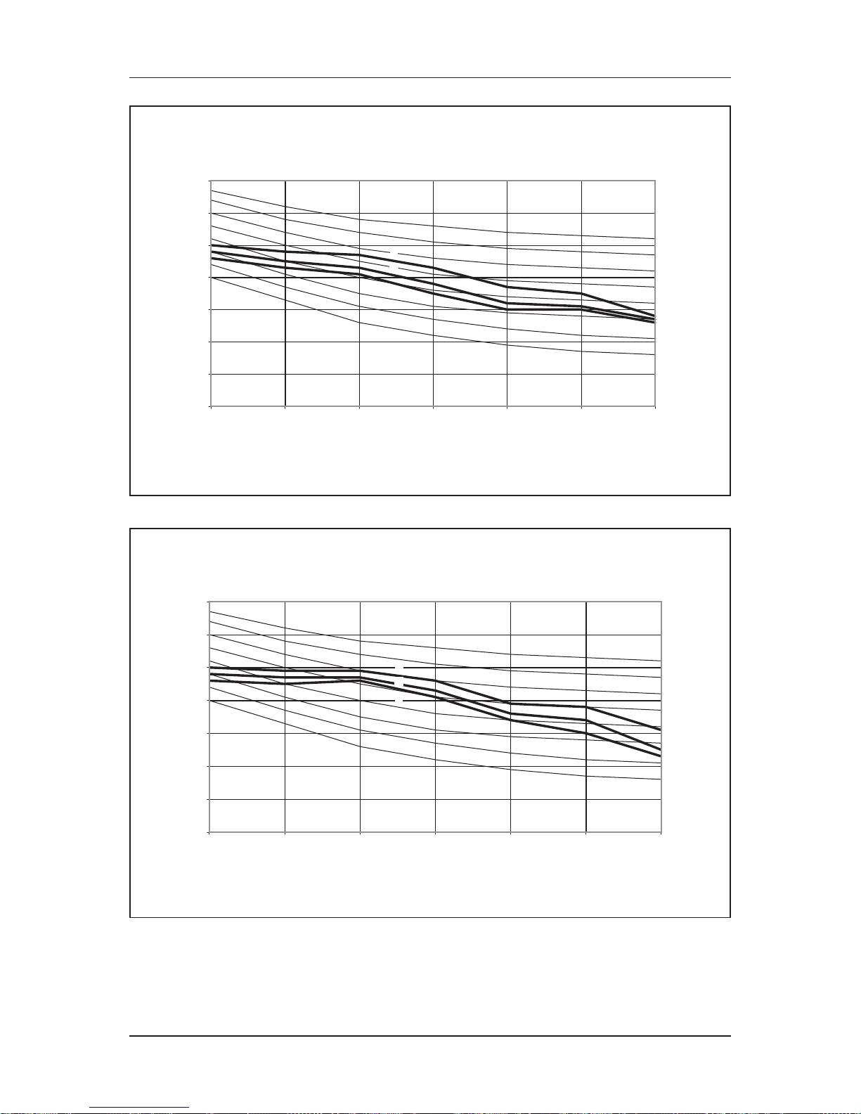
MWM25LW
0
10
20
30
40
50
60
70
Octave-band frequency (Hz)
Sound pressure level (dB, ref 20PPa)
NC-20
NC-30
NC-25
NC-35
NC-40
NC-45
NC-50
NC-55
H
M
L
125 250 500 1000 2000 4000 8000
MWM301W
0
10
20
30
40
50
60
70
125 250 500 1000 2000 4000 8000
Octave-band frequency (Hz)
Sound pressure level (dB, ref 20μPa)
NC-20
NC-30
NC-25
NC-35
NC-40
NC-45
NC-50
NC-55
H
M
L
Page 28
25
Sound Data
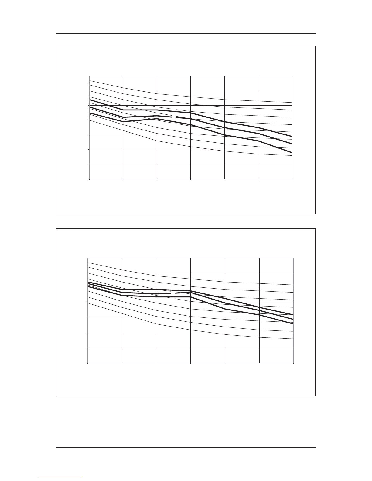
MCK020AW/AWH
0
10
20
30
40
50
60
70
125 250 500 1000 2000 4000 8000
Octave-band frequency (Hz)
Sound pressure level (dB, ref 20μPa)
NC-20
NC-30
NC-25
NC-35
NC-40
NC-45
NC-50
NC-55
H
M
L
MCK025AW/AWH
0
10
20
30
40
50
60
70
125 250 500 1000 2000 4000 8000
Octave-band frequency (Hz)
Sound pressure level (dB, ref 20μPa)
NC-20
NC-30
NC-25
NC-35
NC-40
NC-45
NC-50
NC-55
H
M
L
Page 29
26
Sound Data
MCK030AW/AWH
0
10
20
30
40
50
60
70
125 250 500 1000 2000 4000 8000
Octave-band frequency (Hz)
Sound pressure level (dB, ref 20μPa)
NC-20
NC-30
NC-25
NC-35
NC-40
NC-45
NC-50
NC-55
H
M
L
MCK040AW/AWH
0
10
20
30
40
50
60
70
125 250 500 1000 2000 4000 8000
Octave-band frequency (Hz)
Sound pressure level (dB, ref 20μPa)
NC-20
NC-30
NC-25
NC-35
NC-40
NC-45
NC-50
NC-55
H
M
L
Page 30

27
Sound Data
MCK050AW/AWH
0
10
20
30
40
50
60
70
125 250 500 1000 2000 4000 8000
Octave-band frequency (Hz)
Sound pressure level (dB, ref 20μPa)
NC-20
NC-30
NC-25
NC-35
NC-40
NC-45
NC-50
NC-55
H
M
L
MCK10CW
0
10
20
30
40
50
60
70
125 250 500 1000 2000 4000 8000
Octave-band frequency (Hz)
Sound pressure level (dB, ref 20μPa)
NC-20
NC-30
NC-25
NC-35
NC-40
NC-45
NC-50
NC-55
H
M
L
Page 31

28
Sound Data
MCK15CW
0
10
20
30
40
50
60
70
125 250 500 1000 2000 4000 8000
Octave-band frequency (Hz)
Sound pressure level (dB, ref 20PPa)
NC-20
NC-30
NC-25
NC-35
NC-40
NC-45
NC-50
NC-55
H
M
L
MCK20CW
0
10
20
30
40
50
60
70
125 250 500 1000 2000 4000 8000
Octave-band frequency (Hz)
Sound pressure level (dB, ref 20PPa)
NC-20
NC-30
NC-25
NC-35
NC-40
NC-45
NC-50
NC-55
H
M
L
Page 32

29
Sound Data
MCK20EW
0
10
20
30
40
50
60
70
125 250 500 1000 2000 4000 8000
Octave-band frequency (Hz)
Sound pressure level (dB, ref 20μPa)
NC-20
NC-30
NC-25
NC-35
NC-40
NC-45
NC-50
NC-55
H
M
L
MCK25EW
0
10
20
30
40
50
60
70
125 250 500 1000 2000 4000 8000
Octave-band frequency (Hz)
Sound pressure level (dB, ref 20PPa)
NC-20
NC-30
NC-25
NC-35
NC-40
NC-45
NC-50
NC-55
H
M
L
Page 33

30
Sound Data
MCK30EW
0
10
20
30
40
50
60
70
125 250 500 1000 2000 4000 8000
Octave-band frequency (Hz)
Sound pressure level (dB, ref 20PPa)
NC-20
NC-30
NC-25
NC-35
NC-40
NC-45
NC-50
NC-55
H
M
L
MCK40EW
0
10
20
30
40
50
60
70
125 250 500 1000 2000 4000 8000
Octave-band frequency (Hz)
Sound pressure level (dB, ref 20μPa)
NC-20
NC-30
NC-25
NC-35
NC-40
NC-45
NC-50
NC-55
H
M
L
Page 34

31
Sound Data
MCK50EW
0
10
20
30
40
50
60
70
125 250 500 1000 2000 4000 8000
Octave-band frequency (Hz)
Sound pressure level (dB, ref 20PPa)
NC-20
NC-30
NC-25
NC-35
NC-40
NC-45
NC-50
NC-55
H
M
L
MCM020DW
0
10
20
30
40
50
60
70
125 250 500 1000 2000 4000 8000
Octave-band frequency (Hz)
Sound pressure level (dB, ref 20μPa)
NC-20
NC-30
NC-25
NC-35
NC-40
NC-45
NC-50
NC-55
H
M
L
Page 35

32
Sound Data
MCM025DW
0
10
20
30
40
50
60
70
125 250 500 1000 2000 4000 8000
Octave-band frequency (Hz)
Sound pressure level (dB, ref 20μPa)
NC-20
NC-30
NC-25
NC-35
NC-40
NC-45
NC-50
NC-55
H
M
L
MCM030DW
0
10
20
30
40
50
60
70
125 250 500 1000 2000 4000 8000
Octave-band frequency (Hz)
Sound pressure level (dB, ref 20μPa)
NC-20
NC-30
NC-25
NC-35
NC-40
NC-45
NC-50
NC-55
H
M
L
Page 36

33
Sound Data
MCM040DW
0
10
20
30
40
50
60
70
125 250 500 1000 2000 4000 8000
Octave-band frequency (Hz)
Sound pressure level (dB, ref 20μPa)
NC-20
NC-30
NC-25
NC-35
NC-40
NC-45
NC-50
NC-55
H
M
L
MCM050DW
0
10
20
30
40
50
60
70
125 250 500 1000 2000 4000 8000
Octave-band frequency (Hz)
Sound pressure level (dB, ref 20μPa)
NC-20
NC-30
NC-25
NC-35
NC-40
NC-45
NC-50
NC-55
H
M
L
Page 37

34
Sound Data
MCM15EW
0
10
20
30
40
50
60
70
125 250 500 1000 2000 4000 8000
Octave-band frequency (Hz)
Sound pressure level (dB, ref 20μPa)
NC-20
NC-30
NC-25
NC-35
NC-40
NC-45
NC-50
NC-55
H
M
L
MCM20EW
0
10
20
30
40
50
60
70
125 250 500 1000 2000 4000 8000
Octave-band frequency (Hz)
Sound pressure level (dB, ref 20μPa)
NC-20
NC-30
NC-25
NC-35
NC-40
NC-45
NC-50
NC-55
H
M
L
Page 38

35
Sound Data
MCM25EW
0
10
20
30
40
50
60
70
125 250 500 1000 2000 4000 8000
Octave-band frequency (Hz)
Sound pressure level (dB, ref 20μPa)
NC-20
NC-30
NC-25
NC-35
NC-40
NC-45
NC-50
NC-55
H
M
L
MCC10CW
0
10
20
30
40
50
60
70
125 250 500 1000 2000 4000 8000
Octave-band frequency (Hz)
Sound pressure level (dB, ref 20μPa)
NC-20
NC-30
NC-25
NC-35
NC-40
NC-45
NC-50
NC-55
H
M
L
Page 39

36
Sound Data
MCC15CW
0
10
20
30
40
50
60
70
125 250 500 1000 2000 4000 8000
Octave-band frequency (Hz)
Sound pressure level (dB, ref 20PPa)
NC-20
NC-30
NC-25
NC-35
NC-40
NC-45
NC-50
NC-55
H
M
L
MCC20CW
0
10
20
30
40
50
60
70
125 250 500 1000 2000 4000 8000
Octave-band frequency (Hz)
Sound pressure level (dB, ref 20PPa)
NC-20
NC-30
NC-25
NC-35
NC-40
NC-45
NC-50
NC-55
H
M
L
Page 40

37
Sound Data
MCC25CW
0
10
20
30
40
50
60
70
125 250 500 1000 2000 4000 8000
Octave-band frequency (Hz)
Sound pressure level (dB, ref 20μPa)
NC-20
NC-30
NC-25
NC-35
NC-40
NC-45
NC-50
NC-55
H
M
L
MCC28CW
0
10
20
30
40
50
60
70
125 250 500 1000 2000 4000 8000
Octave-band frequency (Hz)
Sound pressure level (dB, ref 20PPa)
NC-20
NC-30
NC-25
NC-35
NC-40
NC-45
NC-50
NC-55
H
M
L
Page 41

38
Sound Data
MCC30CW
0
10
20
30
40
50
60
70
125 250 500 1000 2000 4000 8000
Octave-band frequency (Hz)
Sound pressure level (dB, ref 20μPa)
NC-20
NC-30
NC-25
NC-35
NC-40
NC-45
NC-50
NC-55
H
M
L
MCC38CW
0
10
20
30
40
50
60
70
125 250 500 1000 2000 4000 8000
Octave-band frequency (Hz)
Sound pressure level (dB, ref 20PPa)
NC-20
NC-30
NC-25
NC-35
NC-40
NC-45
NC-50
NC-55
H
M
L
Page 42
39
Sound Data
MCC40CW
0
10
20
30
40
50
60
70
125 250 500 1000 2000 4000 8000
Octave-band frequency (Hz)
Sound pressure level (dB, ref 20PPa)
NC-20
NC-30
NC-25
NC-35
NC-40
NC-45
NC-50
NC-55
H
M
L
MCC50CW
0
10
20
30
40
50
60
70
125 250 500 1000 2000 4000 8000
Octave-band frequency (Hz)
Sound pressure level (dB, ref 20μPa)
NC-20
NC-30
NC-25
NC-35
NC-40
NC-45
NC-50
NC-55
H
M
L
Page 43

40
Sound Data
MCC60CW
0
10
20
30
40
50
60
70
125 250 500 1000 2000 4000 8000
Octave-band frequency (Hz)
Sound pressure level (dB, ref 20PPa)
NC-20
NC-30
NC-25
NC-35
NC-40
NC-45
NC-50
NC-55
H
M
L
MDB75BW
0
10
20
30
40
50
60
70
125 250 500 1000 2000 4000 8000
Octave-band frequency (Hz)
Sound pressure level (dB, ref 20μPa)
NC-20
NC-30
NC-25
NC-35
NC-40
NC-45
NC-50
NC-55
H
M
L
Page 44

41
Sound Data
MDB100BW
0
10
20
30
40
50
60
70
125 250 500 1000 2000 4000 8000
Octave-band frequency (Hz)
Sound pressure level (dB, ref 20PPa)
NC-20
NC-30
NC-25
NC-35
NC-40
NC-45
NC-50
NC-55
H
M
L
MDB125BW
0
10
20
30
40
50
60
70
125 250 500 1000 2000 4000 8000
Octave-band frequency (Hz)
Sound pressure level (dB, ref 20PPa)
NC-20
NC-30
NC-25
NC-35
NC-40
NC-45
NC-50
NC-55
H
Page 45
42
Sound Data
MDB150BW
0
10
20
30
40
50
60
70
125 250 500 1000 2000 4000 8000
Octave-band frequency (Hz)
Sound pressure level (dB, ref 20μPa)
NC-20
NC-30
NC-25
NC-35
NC-40
NC-45
NC-50
NC-55
H
Page 46
43
Selection Process
Selection Process
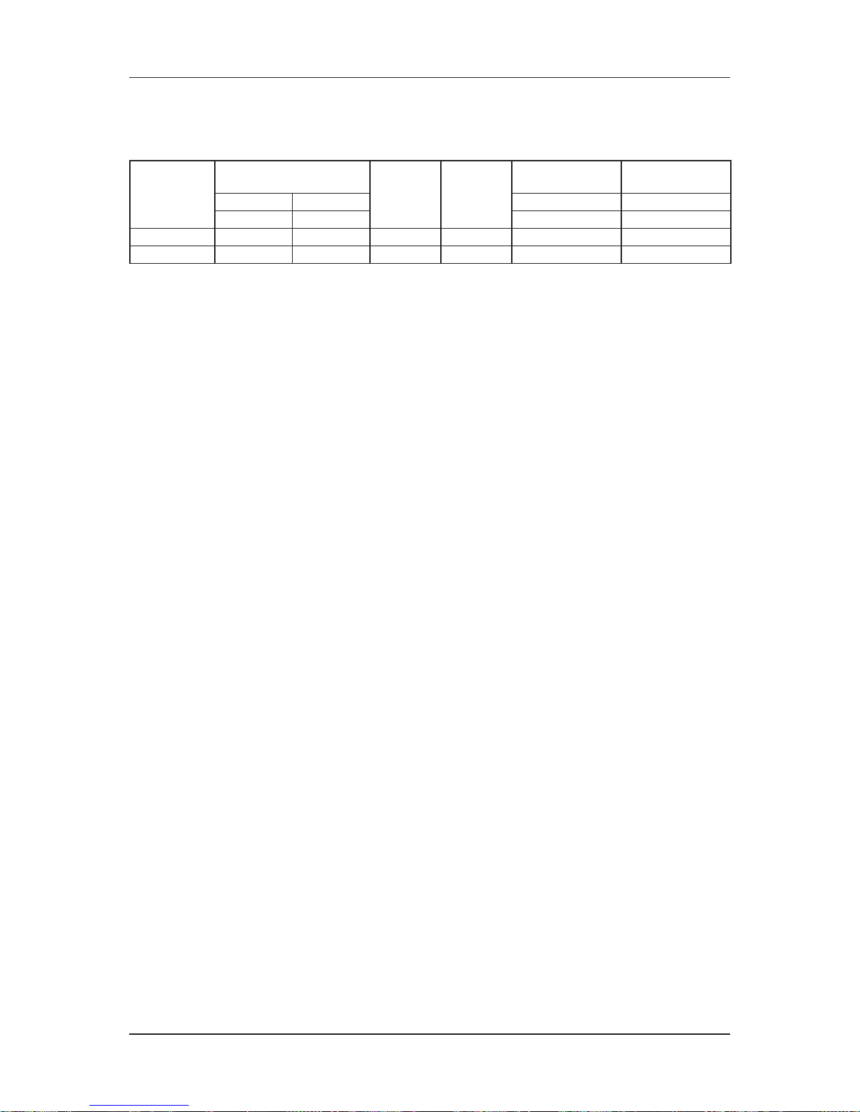
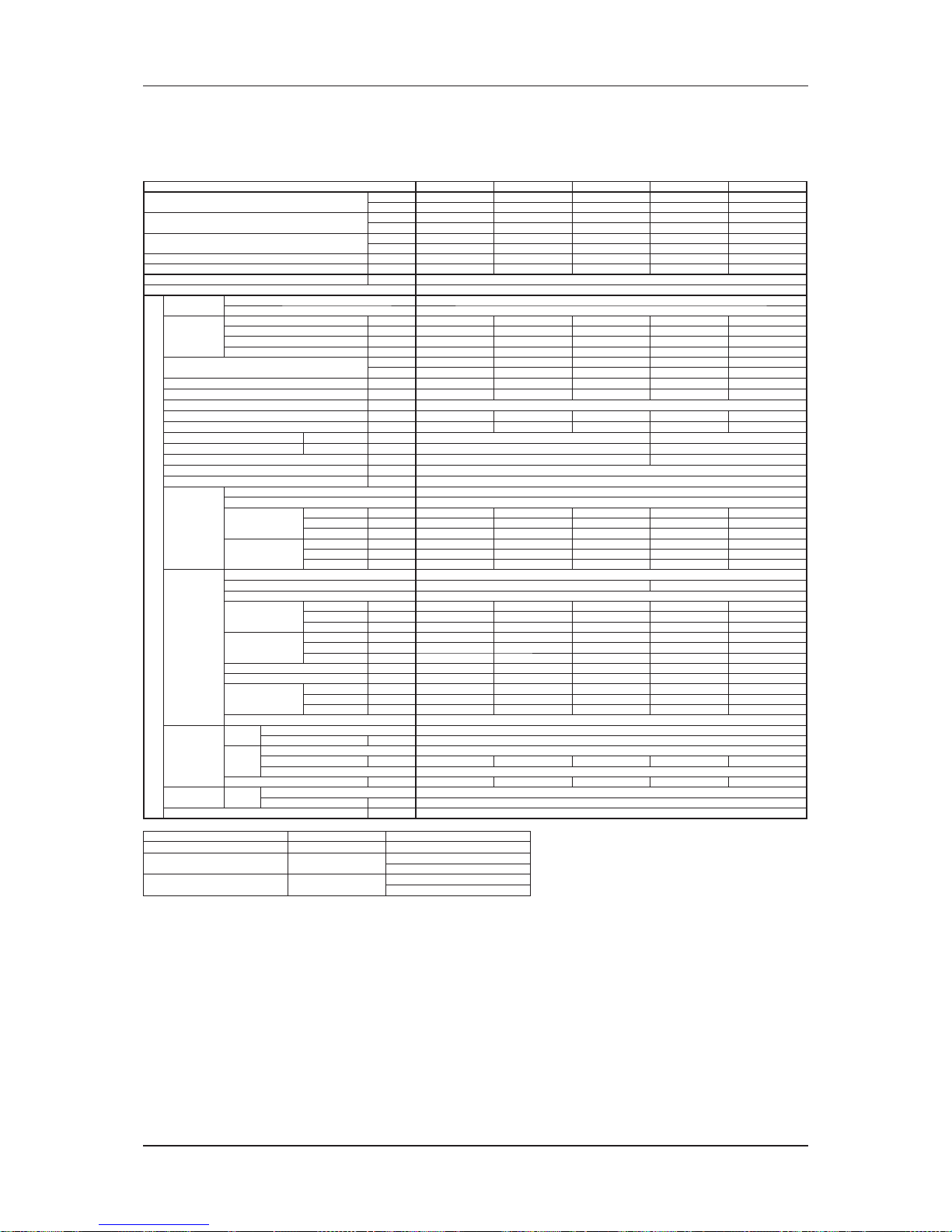
The following table summarizes the pulley data, motor size used for the MDB series, as manufactured:
Model
Pulley Center Distance, C
Motor, kW Motor RPM
Motor Pulley
Diameter, Dm
Blower Pulley, Db
Horizontal Vertical Taper # Taper #
(mm) (mm) (mm) (mm)
MDB125BW
340 350 1.5 1500 80 150
MDB150BW
320 N/A 2.2 1500 80 160
Page 47
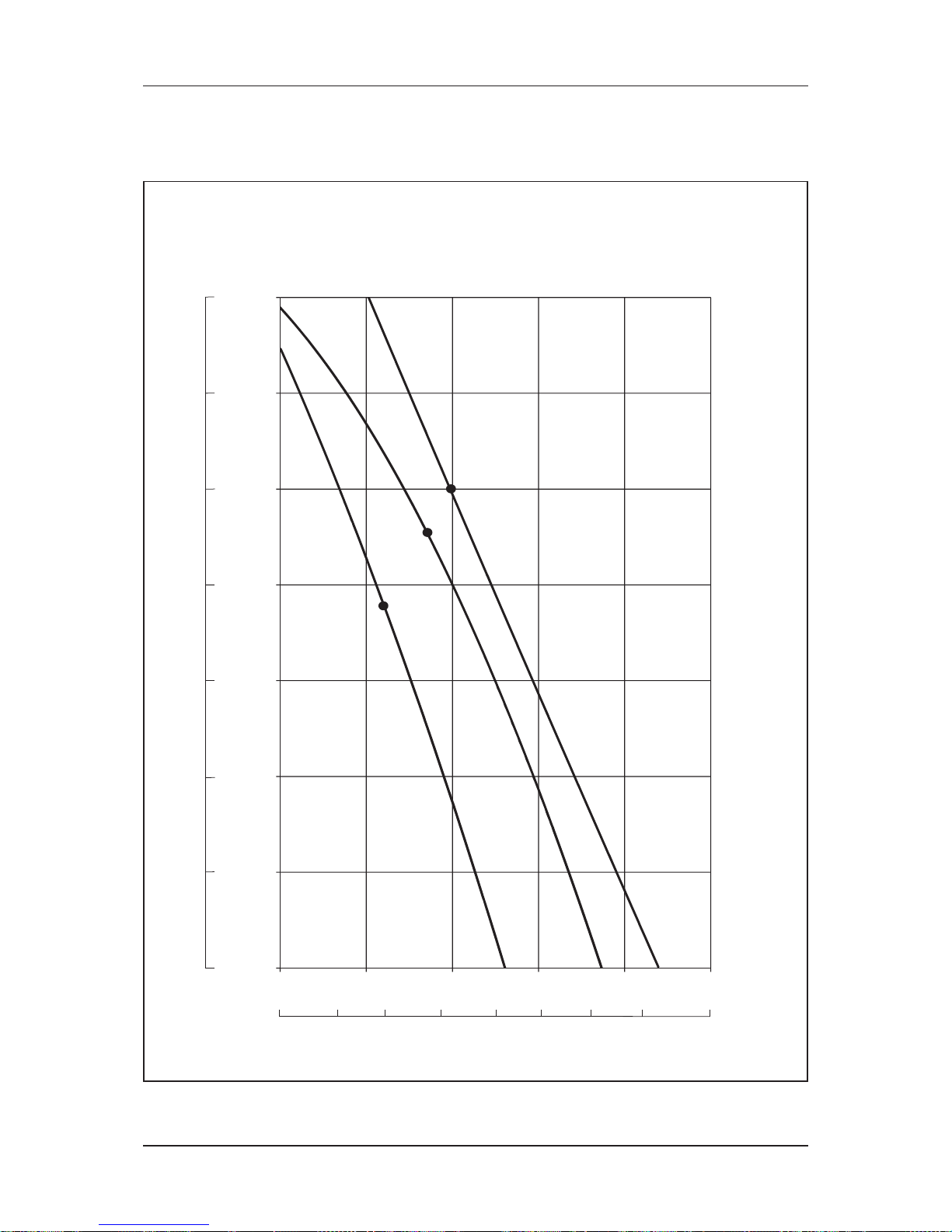
44
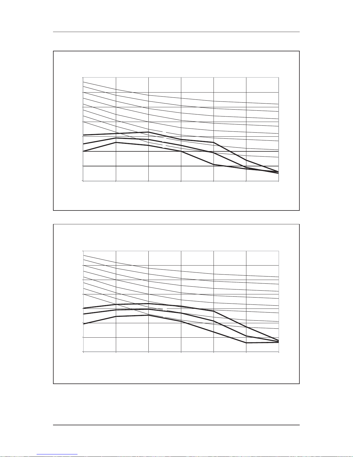
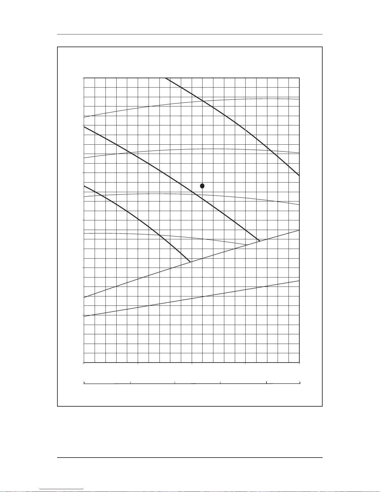
Fan Performance Chart
Fan Performance Chart
Fan Performance Curve
0
1
2
3
4
5
6
7
200 250 300 350 400 450
HIGH
MEDIUM
LOW
Pa mmAq
340
400 450 500 550 600 650 700 765
CFM
CMH
69
59
49
39
29
20
10
0
External Static Pressure
Air Flow
MCC10CW
Page 48
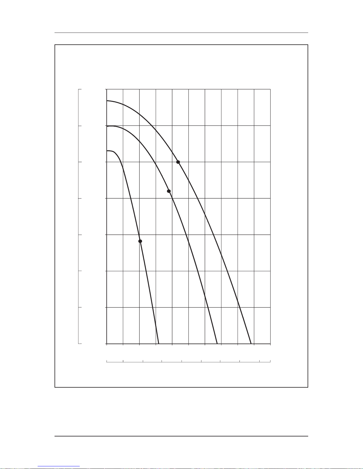
45
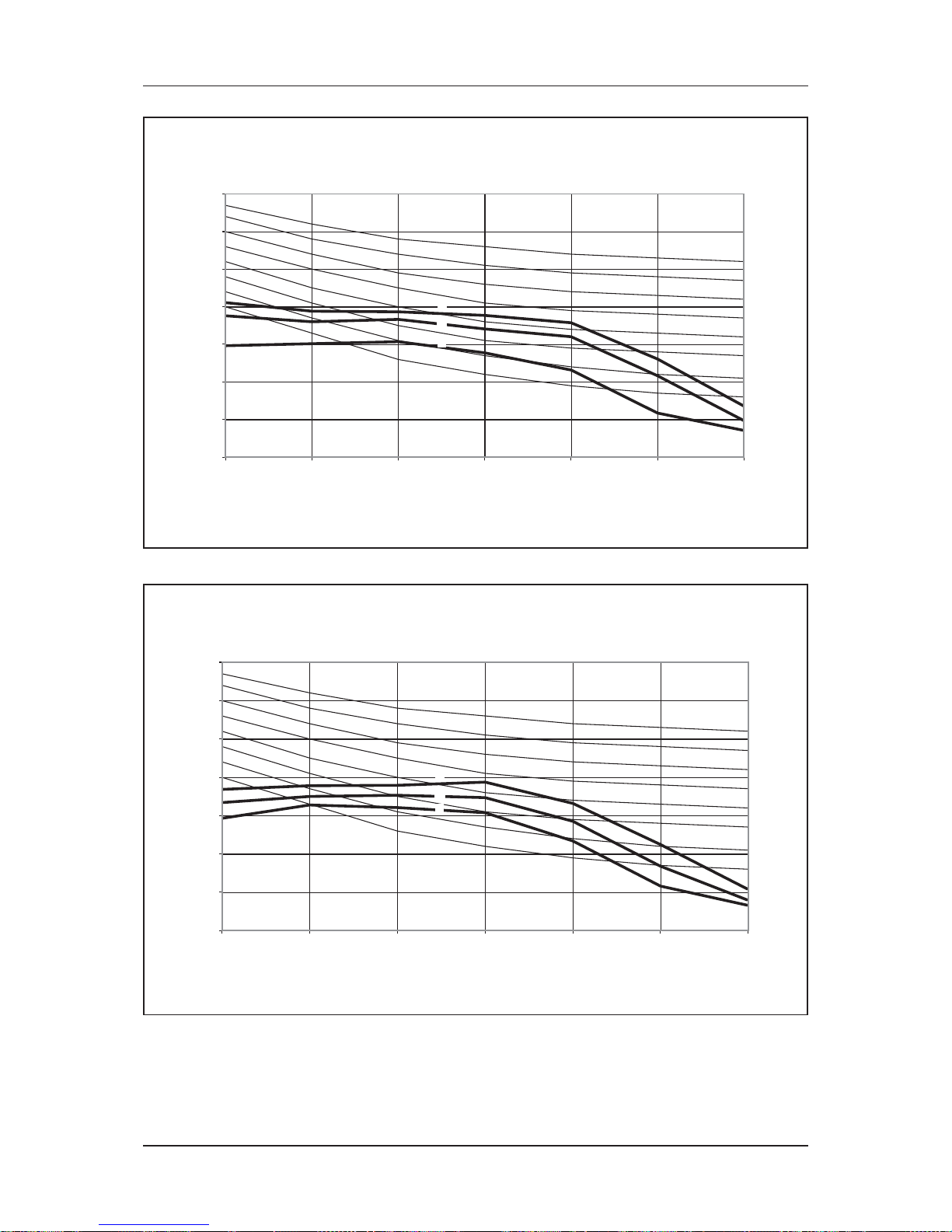
Fan Performance Chart
0
1
2
3
4
5
6
7
300 350 400 450 500 550 600 650 700 750 800
HIGH
MEDIUM
LOW
Pa mmAq
510 600 700 800 900 1000 1100 1200 1300 1360
CFM
CMH
69
59
49
39
29
20
10
0
External Static Pressure
Air Flow
MCC15CW
Page 49
46
Fan Performance Chart
0
1
2
3
4
5
6
7
550 600 650 700 750 800 850 900 950
HIGH
MEDIUM
LOW
Pa mmAq
CFM
CMH
69
59
49
39
29
20
10
0
935 1000 1100 1200 1300 1400 1500 1615
External Static Pressure
Air Flow
MCC20CW
Page 50
47
Fan Performance Chart
0
1
2
3
4
5
6
7
450 500 550 600 650 700 750 800 850 900 950
HIGH
MEDIUM
LOW
Pa mmAq
765 900 1000 1100 1200 1300 1400 1500 1615
CFM
CMH
69
59
49
39
29
20
10
0
External Static Pressure
Air Flow
MCC25CW
Page 51

48
Fan Performance Chart
0
2
4
6
8
10
12
300 400 500 600 700 800 900 1000 1100 1200
HIGHMEDIUMLOW
118
98
78
59
39
20
0
Pa mmAq
510 700 900 1100 1300 1500 1700 1900 2040
CFM
CMH
External Static Pressure
Air Flow
MCC28CW
Page 52

49
Fan Performance Chart
0
2
4
6
8
10
12
14
16
18
400 600 800 1000 1200 1400
HIGH
MEDIUM
LOW
177
157
137
118
98
78
59
39
20
0
Pa mmAq
680 900 1100 1300 1500 1700 1900 2100 2380
CFM
CMH
External Static Pressure
Air Flow
MCC30CW
Page 53

50
Fan Performance Chart
0
2
4
6
8
10
12
14
16
18
400 600 800 1000 1200 1400
HIGH
MEDIUM
LOW
177
157
137
118
98
78
59
39
20
0
Pa mmAq
680 900 1100 1300 1500 1700 1900 2100 2380
CF
M
CM
H
External Static Pressure
Air Flow
MCC38CW
Page 54

51
Fan Performance Chart
0
2
4
6
8
10
12
14
16
18
600 700 800 900 1000 1100 1200 1300 1400 1500
HIGH
MEDIUM
LOW
177
157
137
118
98
78
59
39
20
0
Pa mmAq
1020 1200 1400 1600 1800 2000 2200 2400 2550
CFM
CMH
External Static Pressure
Air Flow
MCC40CW
Page 55

52
Fan Performance Chart
0
2
4
6
8
10
12
14
16
18
900 1000 1100 1200 1300 1400 1500 1600 1700 1800
HIGH
MEDIUM
LOW
177
157
137
118
98
78
59
39
20
0
Pa mmAq
1530 1700 1900 2100 2300 2500 2700 2900 3060
CFM
CMH
External Static Pressure
Air Flow
MCC50CW
Page 56

53
Fan Performance Chart
0
2
4
6
8
10
12
14
16
18
1000 1200 1400 1600 1800 2000
HIGH
MEDIUM
LOW
177
157
137
118
98
78
59
39
20
0
Pa mmAq
1700 1900 2100 2300 2500 2700 2900 3200 3400
CFM
CMH
External Static Pressure
Air Flow
MCC60CW
Page 57

54
Fan Performance Chart
0
2
4
6
8
10
12
14
0 500 1000 1500 2000 2500 3000
HIGH
MEDIUM
LOW
Pa mmAq
0 500 1000 1500 2000 2500 3000 3500 4000 4500 5100
CFM
CMH
137
78
59
39
20
0
118
98
External Static Pressure
Air Flow
MDB75BW
Page 58

55
Fan Performance Chart
0
2
4
6
8
10
12
14
2000 2500 3000 3500 4000
HIGH
MEDIUM
LOW
Pa mmAq
137
78
59
39
20
0
118
98
3400 4000 4500 5000 5500 6000 6500 6800
CFM
CMH
External Static Pressure
Air Flow
MDB100BW
Page 59

56
Fan Performance Chart
0
50
100
150
200
250
300
350
400
450
500
3500 4000 4500 5000
800
700
Internal Static
Pressure with air filter
Standard
Point
CF
M
1.1 kW
L/S
900
1.5 kW
600
Internal Static
Pressure w/o air filter
RPM
1652
1800
2000
2200
2360
Total Static Pressure (Pa)
Air Flow
MDB125BW
Page 60
57
Fan Performance Chart
0
100
200
300
400
500
600
3500 4000 4500 5000 5500
CFM
1652
2250
2596
L/s
800
700
Standard
Point
CFM
1.1 kW
900
1.5 kW
2.2 kW
1652
1850
2050
2450
2596
L/s
RPM
Internal Static
Pressure with filter
Internal Static
Pressure w/o filter
1000
Total Static Pressure (Pa)
Air Flow
MDB150BW
Page 61
58
Engineering & Physical Data
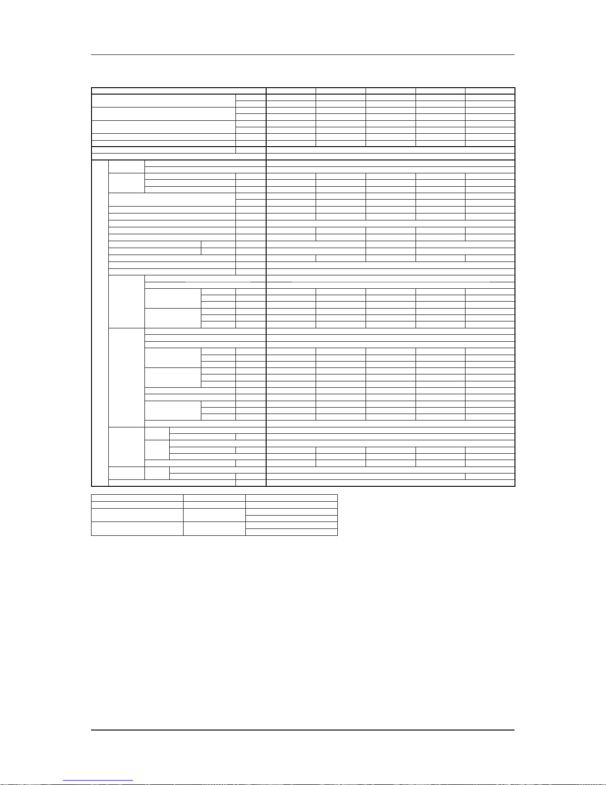
Engineering & Physical Data
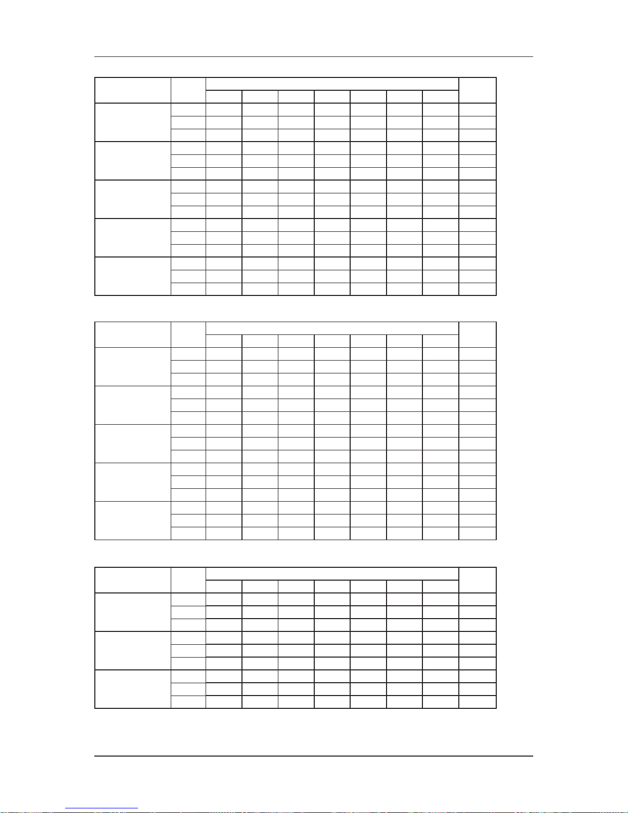
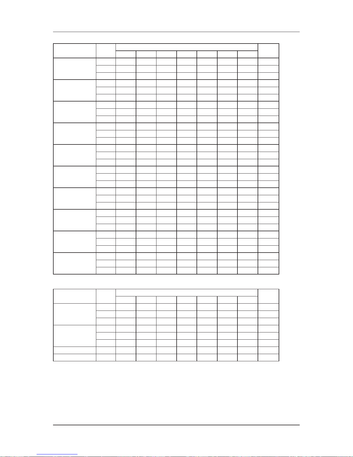
Engineering Data - Chilled Water Fan Coil Unit
MODEL MWM07LW MWM10LW MWM15LW MWM20LW MWM25LW
NOMINAL COOLING CAPACITY
Btu/h 8300 9200 11300 15500 18000
W 2430 2700 3310 4540 5280
NOMINAL SENSIBLE COOLING CAPACITY
Btu/h 6300 6900 9000 11700 14000
W 1850 2020 2640 3430 4100
NOMINAL HEATING CAPACITY
(ENTERING WATER TEMP. = 50°C)
Btu/h 11000 12000 15000 20500 25000
W 3220 3520 4400 6010 7330
NOMINAL TOTAL INPUT POWER W 31 32 42 53 72
NOMINAL RUNNING CURRENT A 0.19 0.20 0.21 0.29 0.34
POWER SOURCE V/Ph/Hz 220-240 / 1 / 50
REFRIGERANT TYPE N/A
INDOOR UNIT
CONTROL
AIR DISCHARGE AUTOMATIC LOUVER (UP & DOWN)
OPERATION LCD WIRELESS MICRO-COMPUTER REMOTE CONTROL
AIR FLOW
HIGH CFM 260 280 370 510 620
MEDIUM CFM 230 250 320 450 520
LOW CFM 200 220 260 390 460
QUIET CFM 180 190 240 360 440
NOMINAL WATER FLOW RATE
USGPM 1.85 2.03 2.51 3.43 4.01
litres/min 7.00 7.68 9.50 13.00 15.18
HEAD LOSS (COOLING)
kPa 34.0 24.0 31.0 30.0 36.0
HEAD LOSS (HEATING) : 50°C
kPa 29.0 20.0 25.0 27.0 33.0
MAX. WORKING PRESSURE
kPa 1608
SURFACE AIR VELOCITY
m/s 0.68 0.74 0.97 0.83 1.01
SOUND PRESSURE LEVEL (H/M/L)
dBA 34 / 29 / 25 / 24 35 / 30 / 25 / 24 42 / 39 / 32 / 29 42 / 38 / 34 / 32 46 / 42 / 39 / 37
UNIT DIMENSION H X W X D
mm 288 X 800 X 206 310 X 1065 X 224
PACKING DIMENSION H X W X D
mm 344 X 874 X 274 386 X 1136 X 314
UNIT WEIGHT
kg 914
CONDENSATE DRAIN SIZE
mm 19.05
PIPE CONNECTION
mm 12.70
FAN
TYPE CROSS FLOW FAN
DRIVE DIRECT
FAN SPEED
HIGH RPM 1030 1050 1310 1035 1250
MEDIUM RPM 890 910 1150 920 1070
LOW RPM 760 780 955 825 970
FAN EFFICIENCY
HIGH % 26.70 24.20 21.00 21.60 20.90
MEDIUM % 25.30 22.70 22.10 21.70 22.20
LOW % 24.80 21.60 22.80 23.10 22.80
FAN MOTOR
TYPE INDUCTION
INDEX OF PROTECTION (IP)
IP20 IP44
INSULATION GRADE E
RATED INPUT
POWER
HIGH W 31 32 42 53 72
MEDIUM W 29 31 37 47 68
LOW W 25 29 33 42 60
RATED RUNNING
CURRENT
HIGH A 0.19 0.20 0.21 0.29 0.34
MEDIUM A 0.18 0.20 0.20 0.26 0.32
LOW A 0.17 0.19 0.19 0.25 0.31
STARTING CURRENT A 0.40 0.40 0.40 0.30 0.43
MOTOR OUTPUT W 18 18 18 26 32
MOTOR
EFFICIENCY
HIGH % 27.40 29.00 44.00 36.50 48.00
MEDIUM % 19.30 21.00 36.00 29.00 36.00
LOW % 13.00 15.00 22.50 24.00 29.00
POLES 4
COIL
TUBE
MATERIAL COPPER
DIAMETER mm 7.00
FIN
MATERIAL ALUMINIUM
FACE AREA m
2
0.18 0.18 0.18 0.29 0.29
ROW 2
WATER VOLUME litre 0.52 0.58 0.58 0.95 0.95
AIR QUALITY FILTER
TYPE WASHABLE SARANET FILTER
QUANTITY pc 2
CASING COLOUR WHITE
MODE COOLING HEATING
ENTERING AIR TEMPERATURE 27°C DB / 19°C WB 20°C DB
ENTERING WATER TEMPERATURE 7°C
50°C (2 Pipes System)
70°C (4 Pipes System)
LEAVING WATER TEMPERATURE 12°C
45°C (2 Pipes System)
60°C (4 Pipes System)
ALL SPECIFICATIONS ARE SUBJECTED TO CHANGE BY THE MANUFACTURER WITHOUT PRIOR NOTICE.
Page 62

59
Engineering & Physical Data
Engineering Data - Chilled Water Fan Coil Unit
MODEL MWM301W
NOMINAL COOLING CAPACITY
Btu/h 22000
W 6450
NOMINAL SENSIBLE COOLING CAPACITY
Btu/h 16720
W 4900
NOMINAL HEATING CAPACITY
(ENTERING WATER TEMP. = 50°C)
Btu/h 23000
W 6740
NOMINAL TOTAL INPUT POWER W 74
NOMINAL RUNNING CURRENT A 0.32
POWER SOURCE V/Ph/Hz 220-240 / 1 / 50
REFRIGERANT TYPE N/A
INDOOR UNIT
CONTROL
AIR DISCHARGE
AUTOMATIC LOUVER
(UP & DOWN)
OPERATION
LCD WIRELESS
MICRO-COMPUTER
REMOTE CONTROL
AIR FLOW
HIGH CFM 670
MEDIUM CFM 630
LOW CFM 500
QUIET CFM N/A
NOMINAL WATER FLOW RATE
USGPM 4.90
litres/min 18.50
HEAD LOSS (COOLING)
kPa 52.2
HEAD LOSS (HEATING) : 50°C
kPa 18.8
MAX. WORKING PRESSURE
kPa 1608
SURFACE AIR VELOCITY
m/s 1.09
SOUND PRESSURE LEVEL (H/M/L)
dBA 49 / 47 / 45
UNIT DIMENSION H X W X D
mm 291 X 815 X 181
PACKING DIMENSION H X W X D
mm 760 X 1311 X 301
UNIT WEIGHT kg 17.6
CONDENSATE DRAIN SIZE mm 19.05
PIPE CONNECTION mm 12.70
FAN
TYPE CROSS FLOW FAN
DRIVE DIRECT
FAN SPEED
HIGH RPM 1322
MEDIUM RPM 1240
LOW RPM 111 2
FAN EFFICIENCY
HIGH % N/A
MEDIUM % N/A
LOW % N/A
FAN MOTOR
TYPE INDUCTION
INDEX OF PROTECTION (IP)
IPX0
INSULATION GRADE B
RATED INPUT
POWER
HIGH W 74
MEDIUM W 59
LOW W 46
RATED RUNNING
CURRENT
HIGH A 0.32
MEDIUM A 0.26
LOW A 0.21
STARTING CURRENT A N/A
MOTOR OUTPUT W 40
MOTOR
EFFICIENCY
HIGH % N/A
MEDIUM % N/A
LOW % N/A
POLES 4
COIL
TUBE
MATERIAL COPPER
DIAMETER mm 9.52
FIN
MATERIAL ALUMINIUM
FACE AREA m
2
0.29
ROW 2
WATER VOLUME litre 1.425
AIR
QUALITY
FILTER
TYPE
WASHABLE SARANET
FILTER
QUANTITY pc 2
CASING COLOUR WHITE
MODE COOLING HEATING
ENTERING AIR TEMPERATURE 27°C DB / 19°C WB 20°C DB
ENTERING WATER TEMPERATURE 7°C
50°C (2 Pipes System)
70°C (4 Pipes System)
LEAVING WATER TEMPERATURE 12°C
45°C (2 Pipes System)
60°C (4 Pipes System)
ALL SPECIFICATIONS ARE SUBJECTED TO CHANGE BY THE MANUFACTURER WITHOUT PRIOR NOTICE.
Page 63

60
Engineering & Physical Data
Engineering Data - Chilled Water Fan Coil Unit
MODEL MCK020AW MCK025AW MCK030AW MCK040AW MCK050AW
NOMINAL COOLING CAPACITY
Btu/h 22500 25500 30000 33500 36500
W 6590 7470 8790 9820 10700
NOMINAL SENSIBLE COOLING CAPACITY
Btu/h 16700 18400 21800 24200 26250
W 4890 5390 6390 7090 7690
NOMINAL HEATING CAPACITY
(ENTERING WATER TEMP. = 50°C)
Btu/h 28500 32000 37500 40500 44000
W 8350 9380 10990 11870 12900
NOMINAL TOTAL INPUT POWER W 127 151 164 192 253
NOMINAL RUNNING CURRENT A 0.52 0.64 0.68 0.79 1.06
POWER SOURCE V/Ph/Hz 220-240 / 1 / 50
REFRIGERANT TYPE N/A
INDOOR UNIT
CONTROL
AIR DISCHARGE 4 WAY AUTOMATIC LOUVER (UP & DOWN)
OPERATION LCD WIRELESS MICRO-COMPUTER REMOTE CONTROL
AIR FLOW
HIGH CFM 771 812 918 1024 1083
MEDIUM CFM 665 695 777 900 989
LOW CFM 630 630 712 789 906
NOMINAL WATER FLOW RATE
USGPM 5.00 5.68 6.65 7.53 8.19
litres/min 18.93 21.50 25.17 28.50 31.00
HEAD LOSS (COOLING)
kPa 24.8 30.8 41.6 52.2 69.3
HEAD LOSS (HEATING) : 50°C
kPa 21.4 26.8 35.3 45.2 64.1
MAX. WORKING PRESSURE
kPa 1608
SURFACE AIR VELOCITY
m/s 0.77 0.82 0.92 1.03 1.09
SOUND PRESSURE LEVEL (H/M/L)
dBA 42 / 39 / 37 45 / 42 / 40 49 / 45 / 43 51 / 48 / 46 53 / 52 / 50
UNIT DIMENSION - ( ) WITH PANEL H X W X D
mm 305 X 824 X 824 (355 X 930 X 930)
PACKING DIMENSION - ( ) PANEL H X W X D
mm 371 X 916 X 916 (121 X 1000 X 1016)
UNIT WEIGHT (UNIT + PANEL)
kg 25 + 4 36 + 4 38 + 4 42 + 4 44 + 4
CONDENSATE DRAIN SIZE mm 19.05
PIPE CONNECTION mm 19.05
FAN
TYPE TURBO FAN
DRIVE DIRECT
FAN SPEED
HIGH RPM 440 500 570 620 655
MEDIUM RPM 380 440 480 550 590
LOW RPM 360 400 440 490 560
FAN EFFICIENCY
HIGH % 23.80 30.00 31.90 34.30 28.80
MEDIUM % 27.70 29.10 32.80 34.90 30.80
LOW % 28.00 29.30 37.60 35.90 32.50
FAN MOTOR
TYPE INDUCTION
INDEX OF PROTECTION (IP)
IP22
INSULATION GRADE B
RATED INPUT POWER
HIGH W 127 151 164 192 253
MEDIUM W 115 122 139 155 208
LOW W 102 105 122 121 183
RATED RUNNING
CURRENT
HIGH A 0.52 0.64 0.68 0.79 1.06
MEDIUM A 0.47 0.51 0.58 0.64 0.87
LOW A 0.42 0.45 0.51 0.50 0.78
STARTING CURRENT A 0.58 0.71 0.87 0.92 1.37
MOTOR OUTPUT W 35 45 60 83 120
MOTOR EFFICIENCY
HIGH % 22.00 25.80 30.80 30.70 37.70
MEDIUM % 19.70 21.40 24.10 27.40 31.80
LOW % 18.50 19.10 21.50 23.90 29.40
POLES 8
COIL
TUBE
MATERIAL COPPER
DIAMETER mm 9.53
FIN
MATERIAL ALUMINIUM
FACE AREA m
2
0.47
ROW 2
WATER VOLUME litre 2.69
AIR QUALITY FILTER
TYPE WASHABLE SARANET FILTER
QUANTITY pc 1
CASING COLOUR LIGHT GREY
MODE COOLING HEATING
ENTERING AIR TEMPERATURE 27°C DB / 19°C WB 20°C DB
ENTERING WATER TEMPERATURE 7°C
50°C (2 Pipes System)
70°C (4 Pipes System)
LEAVING WATER TEMPERATURE 12°C
45°C (2 Pipes System)
60°C (4 Pipes System)
ALL SPECIFICATIONS ARE SUBJECTED TO CHANGE BY THE MANUFACTURER WITHOUT PRIOR NOTICE.
Page 64

61
Engineering & Physical Data
Engineering Data - Chilled Water Fan Coil Unit
MODEL MCK020AWH MCK025AWH MCK030AWH MCK040AWH MCK050AWH
NOMINAL COOLING CAPACITY
Btu/h 13000 13500 15500 17000 17500
W 3810 3960 4540 4980 5130
NOMINAL SENSIBLE COOLING CAPACITY
Btu/h 11600 12010 13850 15000 15500
W 3400 3520 4060 4400 4540
NOMINAL HEATING CAPACITY
(ENTERING WATER TEMP. = 50°C)
Btu/h 36000 37500 42500 45500 46500
W 10550 10990 12480 13340 13630
NOMINAL TOTAL INPUT POWER W 122 138 153 184 232
NOMINAL RUNNING CURRENT A 0.53 0.61 0.67 0.80 1.02
POWER SOURCE V/Ph/Hz 220-240 / 1 / 50
REFRIGERANT TYPE N/A
INDOOR UNIT
CONTROL
AIR DISCHARGE 4 WAY AUTOMATIC LOUVER (UP & DOWN)
OPERATION LCD WIRELESS MICRO-COMPUTER REMOTE CONTROL
AIR FLOW
HIGH CFM 771 812 918 1024 1083
MEDIUM CFM 665 695 777 900 989
LOW CFM 630 630 712 789 906
NOMINAL WATER FLOW RATE
USGPM 2.90 3.00 3.52 3.80 3.92
litres/min 11.00 11.40 13.30 14.40 14.80
HEAD LOSS (COOLING)
kPa 3.6 3.8 4.9 5.7 6.0
HEAD LOSS (HEATING) : 50°C
kPa 4.8 5.5 7.2 8.5 8.8
MAX. WORKING PRESSURE
kPa 1608
SURFACE AIR VELOCITY
m/s 0.77 0.82 0.92 1.03 1.09
SOUND PRESSURE LEVEL (H/M/L)
dBA 42 / 39 / 37 45 / 42 / 40 49 / 45 / 43 51 / 48 / 46 53 / 52 / 50
UNIT DIMENSION - ( ) WITH PANEL H X W X D
mm 305 X 824 X 824 (355 X 930 X 930)
PACKING DIMENSION - ( ) PANEL H X W X D
mm 371 X 916 X 916 (121 X 1000 X 1016)
UNIT WEIGHT (UNIT + PANEL)
kg 25 + 4 36 + 4 38 + 4 42 + 4 44 + 4
CONDENSATE DRAIN SIZE mm 19.05
PIPE CONNECTION mm 19.05
FAN
TYPE TURBO FAN
DRIVE DIRECT
FAN SPEED
HIGH RPM 440 500 570 620 700
MEDIUM RPM 380 440 480 550 640
LOW RPM 360 400 440 490 600
FAN EFFICIENCY
HIGH % N/A N/A N/A N/A N/A
MEDIUM % N/A N/A N/A N/A N/A
LOW % N/A N/A N/A N/A N/A
FAN MOTOR
TYPE INDUCTION
INDEX OF PROTECTION (IP)
IP22
INSULATION GRADE B
RATED INPUT
POWER
HIGH W 122 138 153 184 232
MEDIUM W 110 111 129 149 190
LOW W 98 96 113 116 167
RATED RUNNING
CURRENT
HIGH A 0.53 0.61 0.67 0.80 1.02
MEDIUM A 0.48 0.49 0.57 0.65 0.84
LOW A 0.43 0.43 0.50 0.51 0.74
STARTING CURRENT A 0.58 0.71 0.87 0.92 1.37
MOTOR OUTPUT W 35 45 60 83 120
MOTOR EFFICIENCY
HIGH % N/A N/A N/A N/A N/A
MEDIUM % N/A N/A N/A N/A N/A
LOW % N/A N/A N/A N/A N/A
POLES 8
COIL
TUBE
MATERIAL COPPER
DIAMETER mm 9.53
FIN
MATERIAL ALUMINIUM
FACE AREA m
2
0.47
ROW 1
WATER VOLUME litre 1.34
AIR
QUALITY
FILTER
TYPE WASHABLE SARANET FILTER
QUANTITY pc 1
CASING COLOUR LIGHT GREY
MODE COOLING HEATING
ENTERING AIR TEMPERATURE 27°C DB / 19°C WB 20°C DB
ENTERING WATER TEMPERATURE 7°C
50°C (2 Pipes System)
70°C (4 Pipes System)
LEAVING WATER TEMPERATURE 12°C
45°C (2 Pipes System)
60°C (4 Pipes System)
ALL SPECIFICATIONS ARE SUBJECTED TO CHANGE BY THE MANUFACTURER WITHOUT PRIOR NOTICE.
Page 65

62
Engineering & Physical Data
Engineering Data - Chilled Water Fan Coil Unit
MODEL MCK010CW MCK015CW MCK020CW
NOMINAL COOLING CAPACITY
Btu/h 8500 14000 15500
W 2490 4100 4540
NOMINAL SENSIBLE COOLING CAPACITY
Btu/h 6500 10000 11500
W 1910 2930 3370
NOMINAL HEATING CAPACITY
(ENTERING WATER TEMP. = 50°C)
Btu/h 12000 16000 18000
W 3520 4690 5280
NOMINAL TOTAL INPUT POWER W 63 64 79
NOMINAL RUNNING CURRENT A 0.28 0.28 0.35
POWER SOURCE V/Ph/Hz 220-240 / 1 / 50
REFRIGERANT TYPE N/A
INDOOR UNIT
CONTROL
AIR DISCHARGE 4 WAY AUTOMATIC LOUVER (UP & DOWN)
OPERATION LCD WIRELESS MICRO-COMPUTER REMOTE CONTROL
AIR FLOW
HIGH CFM 380 400 440
MEDIUM CFM 290 310 330
LOW CFM 230 220 280
NOMINAL WATER FLOW RATE
USGPM 2.03 3.43 3.57
litres/min 7.68 12.98 13.51
HEAD LOSS (COOLING)
kPa 19.3 26.9 28.8
HEAD LOSS (HEATING) : 50°C
kPa 16.8 23.9 26.5
MAX. WORKING PRESSURE
kPa 1608
SURFACE AIR VELOCITY
m/s 0.75 0.76 0.83
SOUND PRESSURE LEVEL (H/M/L)
dBA 42 / 35 / 29 45 / 38 / 30 48 / 40 / 36
UNIT DIMENSION - ( ) WITH PANEL H X W X D
mm 250 X 570 X 570 (295 X 640 X 640)
PACKING DIMENSION - ( ) PANEL H X W X D
mm 316 X 630 X 630 (126 X 700 X 726)
UNIT WEIGHT (UNIT + PANEL)
kg 15 + 3 17 + 3 17 + 3
CONDENSATE DRAIN SIZE
mm 19.05
PIPE CONNECTION mm 19.05
FAN
TYPE TURBO FAN
DRIVE DIRECT
FAN SPEED
HIGH RPM 725 810 900
MEDIUM RPM 565 630 700
LOW RPM 460 480 610
FAN EFFICIENCY
HIGH % 38.30 46.90 25.90
MEDIUM % 35.10 45.40 32.30
LOW % 46.70 46.10 21.50
FAN MOTOR
TYPE INDUCTION
INDEX OF PROTECTION (IP)
IP20
INSULATION GRADE B
RATED INPUT
POWER
HIGH W 63 64 79
MEDIUM W 51 58 73
LOW W 46 52 69
RATED RUNNING
CURRENT
HIGH A 0.28 0.28 0.35
MEDIUM A 0.23 0.25 0.32
LOW A 0.21 0.24 0.31
STARTING CURRENT A 0.32 0.30 0.47
MOTOR OUTPUT W 17 23 32
MOTOR
EFFICIENCY
HIGH % 32.20 44.50 49.20
MEDIUM % 20.50 23.60 24.00
LOW % 12.30 11.20 14.80
POLES
6
COIL
TUBE
MATERIAL COPPER
DIAMETER mm 7.00
FIN
MATERIAL ALUMINIUM
FACE AREA m
2
0.24 0.25 0.25
ROW 122
WATER VOLUME litre 0.43 0.83 0.83
AIR
QUALITY
FILTER
TYPE WASHABLE SARANET FILTER
QUANTITY pc 1
CASING COLOUR LIGHT GREY
MODE COOLING HEATING
ENTERING AIR TEMPERATURE 27°C DB / 19°C WB 20°C DB
ENTERING WATER TEMPERATURE 7°C
50°C (2 Pipes System)
70°C (4 Pipes System)
LEAVING WATER TEMPERATURE 12°C
45°C (2 Pipes System)
60°C (4 Pipes System)
ALL SPECIFICATIONS ARE SUBJECTED TO CHANGE BY THE MANUFACTURER WITHOUT PRIOR NOTICE.
Page 66

63
Engineering & Physical Data
Engineering Data - Chilled Water Fan Coil Unit
MODEL MCK020EW MCK025EW MCK030EW MCK040EW MCK050EW
NOMINAL COOLING CAPACITY
Btu/h 21000 25000 30000 38000 43000
W 6150 7330 8790 11140 12600
NOMINAL SENSIBLE COOLING CAPACITY
Btu/h 15900 19200 22300 27400 31000
W 4660 5630 6540 8030 9090
NOMINAL HEATING CAPACITY
(ENTERING WATER TEMP. = 50°C)
Btu/h 28000 33600 38300 45500 52000
W 8210 9850 11230 13340 15240
NOMINAL TOTAL INPUT POWER W 95 126 167 186 227
NOMINAL RUNNING CURRENT A 0.44 0.55 0.74 0.85 1.03
POWER SOURCE V/Ph/Hz 220-240 / 1 / 50
REFRIGERANT TYPE N/A
INDOOR UNIT
CONTROL
AIR DISCHARGE 4 WAY AUTOMATIC LOUVER (UP & DOWN)
OPERATION LCD WIRELESS MICRO-COMPUTER REMOTE CONTROL
AIR FLOW
HIGH CFM 750 860 890 1000 1140
MEDIUM CFM 620 700 720 840 1000
LOW CFM 480 540 570 680 840
QUIET CFM 320 380 420 540 700
NOMINAL WATER FLOW RATE
USGPM 4.45 5.59 6.69 8.45 9.60
litres/min 16.82 21.17 25.29 31.94 36.29
HEAD LOSS (COOLING)
kPa 20 37 22 44 53
HEAD LOSS (HEATING) : 50°C
kPa 19 33 19 38 47
MAX. WORKING PRESSURE
kPa 1608
SURFACE AIR VELOCITY
m/s 0.91 1.04 1.14 1.03 1.17
SOUND PRESSURE LEVEL (H/M/L/Q)
dBA 42 / 38 / 32 / 23 46 / 42 / 35 / 27 48 / 43 / 38 / 30 48 / 43 / 39 / 33 51 / 48 / 43 / 39
UNIT DIMENSION - ( ) WITH PANEL H X W X D
mm 265 X 820 X 820 (300 X 900 X 900) 300 X 820 X 820 (335 X 900 X 900)
PACKING DIMENSION - ( ) PANEL H X W X D
mm 300 X 900 X 900 (110 X 1120 X 1120) 335 X 900 X 900 (110 X 1120 X 1120)
UNIT WEIGHT (UNIT + PANEL)
kg 26 + 4 26 + 4 28 + 4 32 + 4 32 + 4
CONDENSATE DRAIN SIZE
mm 19.05
PIPE CONNECTION mm 19.05
FAN
TYPE TURBO FAN
DRIVE DIRECT
FAN SPEED
HIGH RPM 530 600 660 710 800
MEDIUM RPM 450 500 550 610 710
LOW RPM 360 400 450 510 610
FAN EFFICIENCY
HIGH % N/A N/A N/A N/A N/A
MEDIUM % N/A N/A N/A N/A N/A
LOW % N/A N/A N/A N/A N/A
FAN MOTOR
TYPE INDUCTION
INDEX OF PROTECTION (IP)
IP20
INSULATION GRADE B
RATED INPUT
POWER
HIGH W 95 126 167 186 227
MEDIUM W 79 103 109 151 176
LOW W 67 89 86 118 144
RATED RUNNING
CURRENT
HIGH A 0.44 0.55 0.74 0.85 1.03
MEDIUM A 0.40 0.45 0.49 0.71 0.82
LOW A 0.36 0.39 0.39 0.57 0.69
STARTING CURRENT A 0.44 0.71 0.89 1.02 1.28
MOTOR OUTPUT W 30 45 65 80 110
MOTOR
EFFICIENCY
HIGH % N/A N/A N/A N/A N/A
MEDIUM % N/A N/A N/A N/A N/A
LOW %
N/A N/A N/A N/A N/A
POLES 8
COIL
TUBE
MATERIAL COPPER
DIAMETER mm 7.00
FIN
MATERIAL ALUMINIUM
FACE AREA m
2
0.39 0.39 0.37 0.46 0.46
ROW 22333
WATER VOLUME litre 1.36 1.34 1.97 2.35 2.35
AIR
QUALITY
FILTER
TYPE WASHABLE SARANET FILTER
QUANTITY pc 1
CASING COLOUR LIGHT GREY
MODE COOLING HEATING
ENTERING AIR TEMPERATURE 27°C DB / 19°C WB 20°C DB
ENTERING WATER TEMPERATURE 7°C
50°C (2 Pipes System)
70°C (4 Pipes System)
LEAVING WATER TEMPERATURE 12°C
45°C (2 Pipes System)
60°C (4 Pipes System)
ALL SPECIFICATIONS ARE SUBJECTED TO CHANGE BY THE MANUFACTURER WITHOUT PRIOR NOTICE.
Page 67
64
Engineering & Physical Data
Engineering Data - Chilled Water Fan Coil Unit
MODEL MCM20DW MCM25DW MCM30DW MCM40DW MCM50DW
NOMINAL COOLING CAPACITY
Btu/h 17700 20800 24600 31200 45000
W 5190 6100 7210 9140 13190
NOMINAL SENSIBLE COOLING CAPACITY
Btu/h 13650 15000 17700 25600 31400
W 4000 4400 5190 7500 9200
NOMINAL HEATING CAPACITY
(ENTERING WATER TEMP. = 50°C)
Btu/h 22000 25900 28000 42300 51500
W 6450 7590 8210 12400 15090
NOMINAL TOTAL INPUT POWER W 96 130 132 240 240
NOMINAL RUNNING CURRENT A 0.41 0.54 0.57 0.98 1.03
POWER SOURCE V/Ph/Hz 220-240 / 1 / 50
REFRIGERANT TYPE N/A
INDOOR UNIT
CONTROL
AIR DISCHARGE AUTOMATIC LOUVER (UP & DOWN)
OPERATION LCD WIRELESS MICRO-COMPUTER REMOTE CONTROL
AIR FLOW
HIGH CFM 560 630 698 956 1060
MEDIUM CFM 505 620 688 908 1023
LOW CFM 400 555 650 889 956
NOMINAL WATER FLOW RATE
USGPM 3.92 4.62 5.46 6.91 9.99
litres/min 14.80 17.50 20.70 26.15 37.81
HEAD LOSS (COOLING)
kPa 45.6 55.7 49.4 24.0 37.7
HEAD LOSS (HEATING) : 50°C
kPa 39.2 48.1 43.0 21.5 31.6
MAX. WORKING PRESSURE
kPa 1608
SURFACE AIR VELOCITY
m/s 1.39 1.56 1.37 1.22 1.35
SOUND PRESSURE LEVEL (H/M/L/Q)
dBA 50 / 47 / 40 54 / 53 / 50 51 / 50 / 48 54 / 53 / 52 54 / 53 / 52
UNIT DIMENSION - ( ) WITH PANEL H X W X D
mm 214 X 1214 X 670 249 X 1214 X 670 249 X 1714 X 670
PACKING DIMENSION - ( ) PANEL H X W X D
mm 301 X 1311 X 760 354 X 1376 X 766 354 X 1876 X 766
UNIT WEIGHT (UNIT + PANEL)
kg 43 43 45 70 70
CONDENSATE DRAIN SIZE
mm 19.05
PIPE CONNECTION mm 19.05
FAN
TYPE BLOWER FAN
DRIVE DIRECT
FAN SPEED
HIGH RPM 1200 600 1400 1430 1430
MEDIUM RPM 1100 500 1370 1390 1390
LOW RPM 890 400 1260 1340 1340
FAN EFFICIENCY
HIGH % N/A N/A N/A N/A N/A
MEDIUM % N/A N/A N/A N/A N/A
LOW % N/A N/A N/A N/A N/A
FAN MOTOR
TYPE INDUCTION
INDEX OF PROTECTION (IP)
IP22
INSULATION GRADE B
RATED INPUT
POWER
HIGH W 96 130 132 240 240
MEDIUM W 86 120 121 193 193
LOW W 76 108 108 169 169
RATED RUNNING
CURRENT
HIGH A 0.41 0.54 0.57 0.98 1.03
MEDIUM A 0.37 0.44 0.51 0.8 0.83
LOW A 0.33 0.34 0.46 0.70 0.73
STARTING CURRENT A 0.44 0.71 0.89 1.02 1.28
MOTOR OUTPUT W 40 65 65 100 120
MOTOR EFFICIENCY
HIGH % N/A N/A N/A N/A N/A
MEDIUM % N/A N/A N/A N/A N/A
LOW % N/A N/A N/A N/A N/A
POLES 4
COIL
TUBE
MATERIAL COPPER
DIAMETER mm 9.53
FIN
MATERIAL ALUMINIUM
FACE AREA m
2
0.19 0.19 0.24 0.37 0.37
ROW 33344
WATER VOLUME litre 1.68 1.68 2.09 4.25 4.25
AIR
QUALITY
FILTER
TYPE WASHABLE SARANET FILTER
QUANTITY pc 25
CASING COLOUR LIGHT GREY
MODE COOLING HEATING
ENTERING AIR TEMPERATURE 27°C DB / 19°C WB 20°C DB
ENTERING WATER TEMPERATURE 7°C
50°C (2 Pipes System)
70°C (4 Pipes System)
LEAVING WATER TEMPERATURE 12°C
45°C (2 Pipes System)
60°C (4 Pipes System)
ALL SPECIFICATIONS ARE SUBJECTED TO CHANGE BY THE MANUFACTURER WITHOUT PRIOR NOTICE.
Page 68

65
Engineering & Physical Data
Engineering Data - Chilled Water Fan Coil Unit
MODEL MCM15EW MCM20EW MCM25EW
NOMINAL COOLING CAPACITY
Btu/h 15500 20300 21000
W 4540 5950 6150
NOMINAL SENSIBLE COOLING CAPACITY
Btu/h 12700 15400 16150
W 3720 4510 4730
NOMINAL HEATING CAPACITY
(ENTERING WATER TEMP. = 50°C)
Btu/h 19500 25000 28000
W 5720 7330 8210
NOMINAL TOTAL INPUT POWER W 101 109 113
NOMINAL RUNNING CURRENT A 0.46 0.49 0.52
POWER SOURCE V/Ph/Hz 220-240 / 1 / 50
REFRIGERANT TYPE N/A
INDOOR UNIT
CONTROL
AIR DISCHARGE AUTOMATIC LOUVER (UP & DOWN)
OPERATION LCD WIRELESS MICRO-COMPUTER REMOTE CONTROL
AIR FLOW
HIGH CFM 500 580 620
MEDIUM CFM 450 530 570
LOW CFM 400 490 520
NOMINAL WATER FLOW RATE
USGPM 3.43 4.49 4.67
litres/min 13.00 17.00 17.68
HEAD LOSS (COOLING) kPa 27.4 48.1 57.1
HEAD LOSS (HEATING) : 50°C kPa 24.2 42.1 50.2
MAX. WORKING PRESSURE kPa 1608
SURFACE AIR VELOCITY m/s 0.87 1.01 1.08
SOUND PRESSURE LEVEL dBA 50 / 43 / 41 53 / 51 / 49 56 / 51 / 44
UNIT DIMENSION H X W X D mm 212 X 1090 X 630
PACKING DIMENSION H X W X D mm 297 X 1197 X 740
UNIT WEIGHT kg 27 27 27
CONDENSATE DRAIN SIZE mm 19.05
PIPE CONNECTION mm 12.70
FAN
TYPE BLOWER
DRIVE DIRECT
FAN SPEED
HIGH RPM 1192 1346 1380
MEDIUM RPM 945 1238 1300
LOW RPM 871 1143 1200
FAN EFFICIENCY
HIGH % N/A N/A N/A
MEDIUM % N/A N/A N/A
LOW % N/A N/A N/A
FAN MOTOR
TYPE INDUCTION
INDEX OF PROTECTION (IP) IP22
INSULATION GRADE B
RATED INPUT
POWER
HIGH W 101 109 113
MEDIUM W 98 108 115
LOW W 94 107 113
RATED RUNNING
CURRENT
HIGH A 0.46 0.49 0.52
MEDIUM A 0.43 0.47 0.51
LOW A 0.41 0.47 0.51
STARTING CURRENT A 5.20 10.30 24.00
MOTOR OUTPUT W 50 65 70
MOTOR
EFFICIENCY
HIGH % N/A N/A N/A
MEDIUM % N/A N/A N/A
LOW % N/A N/A N/A
POLES 444
COIL
TUBE
MATERIAL COPPER
DIAMETER mm 6.35
FIN
MATERIAL
ALUMINIUM
FACE AREA m
2
0.27 0.27 0.27
ROW 333
WATER VOLUME litre 1.11 1.11 1.11
AIR
QUALITY
FILTER
TYPE WASHABLE SARANET FILTER
QUANTITY pc 2
CASING COLOUR LIGHT GREY
MODE COOLING HEATING
ENTERING AIR TEMPERATURE 27°C DB / 19°C WB 20°C DB
ENTERING WATER TEMPERATURE 7°C
50°C (2 Pipes System)
70°C (4 Pipes System)
LEAVING WATER TEMPERATURE 12°C
45°C (2 Pipes System)
60°C (4 Pipes System)
ALL SPECIFICATIONS ARE SUBJECTED TO CHANGE BY THE MANUFACTURER WITHOUT PRIOR NOTICE.
Page 69

66
Engineering & Physical Data
Engineering Data - Chilled Water Fan Coil Unit
MODEL MCC010CW MCC015CW MCC020CW MCC025CW MCC028CW
NOMINAL COOLING CAPACITY
Btu/h 9900 11600 18000 22500 20800
W 2900 3400 5280 6590 6100
NOMINAL SENSIBLE COOLING CAPACITY
Btu/h 7000 8120 12600 15750 17000
W 2050 2380 3690 4620 4980
NOMINAL HEATING CAPACITY
(ENTERING WATER TEMP. = 50°C)
Btu/h 11500 15000 23000 29000 29100
W 3370 4400 6740 8500 8530
NOMINAL TOTAL INPUT POWER W 89 140 168 182 277
NOMINAL RUNNING CURRENT A 0.40 0.65 0.77 0.86 1.28
POWER SOURCE V/Ph/Hz 220-240 / 1 / 50
REFRIGERANT TYPE N/A
INDOOR UNIT
CONTROL
AIR DISCHARGE DUCTED
OPERATION WIRED MICRO-COMPUTER REMOTE CONTROL
AIR FLOW
HIGH CFM 300 510 700 730 835
MEDIUM CFM 285 490 675 660 670
LOW CFM 260 400 640 580 550
EXTERNAL STATIC PRESSURE
Pa 49 / 44 / 36 49 / 42 / 28 49 / 45 / 41 49 / 43 / 30 98 / 64 / 44
NOMINAL WATER FLOW RATE
USGPM 2.20 2.60 4.05 5.06 4.67
litres/min 8.33 9.84 15.33 19.15 17.68
HEAD LOSS (COOLING)
kPa 10.5 24.0 20.1 32.4 14.0
HEAD LOSS (HEATING) : 50°C
kPa 8.8 20.3 17.0 27.6 12.0
MAX. WORKING PRESSURE
kPa 1608
SURFACE AIR VELOCITY
m/s 1.29 1.72 1.83 1.72 1.64
SOUND PRESSURE LEVEL (H/M/L)
dBA 36 / 35 / 33 40 / 38 / 33 42 / 41 / 40 41 / 40 / 36 41 / 38 / 34
UNIT DIMENSION H X W X D
mm 266 X 702 X 351 267 X 842 X 351 267 X 1002 X 351 267 X 1137 X 351 296 X 920 X 521
PACKING DIMENSION H X W X D
mm 376 X 951 X 541 376 X 1091 X 541 376 X 1251 X 541 376 X 1386 X 541 343 X 1138 X 690
UNIT WEIGHT
kg 18 22 24 26 35
CONDENSATE DRAIN SIZE mm 19.05
PIPE CONNECTION mm 19.05
FAN
TYPE BLOWER
DRIVE DIRECT
FAN SPEED
HIGH RPM 1221 1211 1410 1355 1266
MEDIUM RPM 1172 1047 1328 1215 1196
LOW RPM 1123 835 1133 937 1150
FAN EFFICIENCY
HIGH % 38.70 42.90 39.70 36.20 45.00
MEDIUM % 40.70 51.90 47.50 38.10 44.50
LOW % 43.00 50.30 48.90 39.10 45.90
FAN MOTOR
TYPE INDUCTION
INDEX OF PROTECTION (IP)
IP20
INSULATION GRADE B
RATED INPUT
POWER
HIGH W 89 140 168 182 277
MEDIUM W 86 128 165 175 180
LOW W 78 127 163 163 158
RATED RUNNING
CURRENT
HIGH A 0.40 0.65 0.77 0.86 1.28
MEDIUM A 0.39 0.59 0.73 0.77 0.81
LOW A 0.35 0.59 0.71 0.71 0.72
STARTING CURRENT A 0.73 1.66 1.22 1.86 1.61
MOTOR OUTPUT W 38 72 80 100 320
MOTOR
EFFICIENCY
HIGH % 47.90 49.70 56.40 57.50 57.90
MEDIUM % 42.40 39.60 50.90 48.40 47.10
LOW %
33.60 24.80 44.10 30.40 30.90
POLES 4
COIL
TUBE
MATERIAL COPPER
DIAMETER mm 9.52
FIN
MATERIAL ALUMINIUM
FACE AREA m
2
0.11 0.14 0.18 0.20 0.24
ROW 3
WATER VOLUME litre 0.94 1.15 1.43 1.63 1.98
AIR
QUALITY
FILTER
TYPE N/A
QUANTITY pc N/A
CASING COLOUR LIGHT GREY
MODE COOLING HEATING
ENTERING AIR TEMPERATURE 27°C DB / 19°C WB 20°C DB
ENTERING WATER TEMPERATURE 7°C
50°C (2 Pipes System)
70°C (4 Pipes System)
LEAVING WATER TEMPERATURE 12°C
45°C (2 Pipes System)
60°C (4 Pipes System)
ALL SPECIFICATIONS ARE SUBJECTED TO CHANGE BY THE MANUFACTURER WITHOUT PRIOR NOTICE.
Page 70
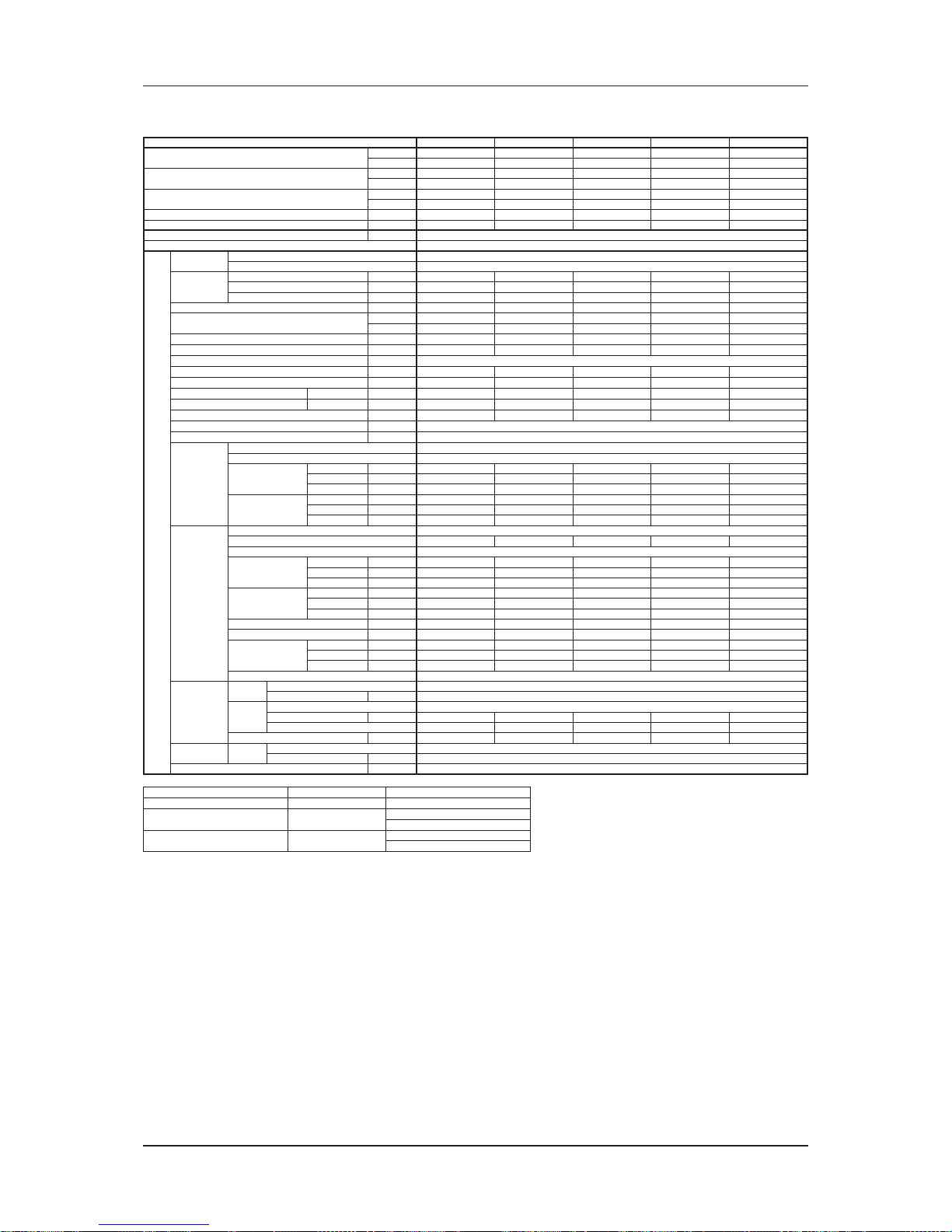
67
Engineering & Physical Data
Engineering Data - Chilled Water Fan Coil Unit
MODEL MCC030CW MCC038CW MCC040CW MCC050CW MCC060CW
NOMINAL COOLING CAPACITY
Btu/h 24800 38000 37000 44700 51800
W 7270 11140 10840 13100 15180
NOMINAL SENSIBLE COOLING CAPACITY
Btu/h 19700 29800 29300 35100 40900
W 5770 8730 8590 10290 11990
NOMINAL HEATING CAPACITY
(ENTERING WATER TEMP. = 50°C)
Btu/h 32800 49200 48000 54900 65300
W 9610 14420 14070 16090 19140
NOMINAL TOTAL INPUT POWER W 345 504 442 427 530
NOMINAL RUNNING CURRENT A 1.50 2.28 1.93 1.86 2.31
POWER SOURCE V/Ph/Hz 220-240 / 1 / 50
REFRIGERANT TYPE N/A
INDOOR UNIT
CONTROL
AIR DISCHARGE DUCTED
OPERATION WIRED MICRO-COMPUTER REMOTE CONTROL
AIR FLOW
HIGH CFM 830 1250 1240 1340 1550
MEDIUM CFM 760 1130 1100 1220 1400
LOW CFM 710 1040 1020 1190 1300
EXTERNAL STATIC PRESSURE Pa 167 / 128 / 88 118 / 108 / 88 128 / 88 / 39 157 / 137 / 108 157 / 137 / 98
NOMINAL WATER FLOW RATE
USGPM 5.55 8.59 8.28 10.04 11.62
litres/min 21.01 32.51 31.34 38.00 43.98
HEAD LOSS (COOLING)
kPa 14.0 39.0 23.0 38.0 51.0
HEAD LOSS (HEATING) : 50°C
kPa 11.0 37.0 19.0 33.0 48.0
MAX. WORKING PRESSURE
kPa 1608
SURFACE AIR VELOCITY
m/s 1.40 1.74 1.83 1.54 1.52
SOUND PRESSURE LEVEL (H/M/L)
dBA 46 / 42 / 38 51 / 48 / 45 49 / 45 / 41 52 / 50 / 47 53 / 50 / 47
UNIT DIMENSION H X W X D
mm 384 X 917 X 462 316 X 1225 X 559 384 X 1003 X 462 384 X 1287 X 462 384 X 1487 X 462
PACKING DIMENSION H X W X D
mm 415 X 1126 X 631 355 X 1461 X 727 415 X 1245 X 631 415 X 1497 X 631 415 X 1701 X 631
UNIT WEIGHT
kg 42 47 44 50 56
CONDENSATE DRAIN SIZE
mm 19.05
PIPE CONNECTION
mm 19.05
FAN
TYPE BLOWER
DRIVE DIRECT
FAN SPEED
HIGH RPM 1180 1406 1279 1279 1351
MEDIUM RPM 1053 1331 1181 1204 1280
LOW RPM 937 1232 1052 1097 1208
FAN EFFICIENCY
HIGH % 37.20 46.00 42.20 43.70 41.70
MEDIUM % 39.50 49.10 42.90 47.30 43.30
LOW % 41.60 44.50 44.30 48.70 43.40
FAN MOTOR
TYPE INDUCTION
INDEX OF PROTECTION (IP)
IP20 IP21 IP22 IP20 IP20
INSULATION GRADE B
RATED INPUT
POWER
HIGH W 345 504 442 427 530
MEDIUM W 304 380 384 388 457
LOW W 270 338 342 373 405
RATED RUNNING
CURRENT
HIGH A 1.50 2.28 1.93 1.86 2.31
MEDIUM A 1.34 1.65 1.69 1.69 2.02
LOW A 1.21 1.48 1.54 1.63 1.85
STARTING CURRENT A 2.43 2.77 3.18 3.50 4.90
MOTOR OUTPUT W 310 470 355 373 500
MOTOR
EFFICIENCY
HIGH % 60.80 63.10 63.80 63.00 68.00
MEDIUM % 47.40 60.80 47.50 58.60 59.60
LOW % 34.80 53.00 32.30 49.40 46.10
POLES 4
COIL
TUBE
MATERIAL COPPER
DIAMETER mm 9.52
FIN
MATERIAL ALUMINIUM
FACE AREA m
2
0.28 0.34 0.32 0.41 0.48
ROW 33333
WATER VOLUME litre 2.21 2.66 2.60 3.33 3.80
AIR
QUALITY
FILTER
TYPE N/A
QUANTITY pc N/A
CASING COLOUR LIGHT GREY
MODE COOLING HEATING
ENTERING AIR TEMPERATURE 27°C DB / 19°C WB 20°C DB
ENTERING WATER TEMPERATURE 7°C
50°C (2 Pipes System)
70°C (4 Pipes System)
LEAVING WATER TEMPERATURE 12°C
45°C (2 Pipes System)
60°C (4 Pipes System)
ALL SPECIFICATIONS ARE SUBJECTED TO CHANGE BY THE MANUFACTURER WITHOUT PRIOR NOTICE.
Page 71

68
Engineering & Physical Data
Engineering Data - Chilled Water Fan Coil Unit
MODEL MDB75BW MDB100BW MDB125BW MDB150BW
NOMINAL COOLING CAPACITY
Btu/h 75600 95000 125000 150000
W 22160 27840 36640 43960
NOMINAL SENSIBLE COOLING CAPACITY
Btu/h 53700 69400 90000 106500
W 15740 20340 26380 31210
NOMINAL HEATING CAPACITY
(ENTERING WATER TEMP. = 50°C)
Btu/h 78000 97500 138000 170000
W 22860 28580 40450 49820
NOMINAL TOTAL INPUT POWER W 760 1800 1620 1910
NOMINAL RUNNING CURRENT A 3.49 7.84 3.33 4.03
POWER SOURCE V/Ph/Hz 220-240 / 1 / 50 380-415 / 3 / 50
REFRIGERANT TYPE N/A
INDOOR UNIT
CONTROL
AIR DISCHARGE DUCTED
OPERATION WITHOUT CONTROLLER
AIR FLOW
HIGH CFM 2500 3200 4200 4600
MEDIUM CFM 2100 3000 N/A N/A
LOW CFM 1750 2800 N/A N/A
EXTERNAL STATIC PRESSURE Pa 100 / 72 / 50 100 / 80 / 60 230 230
NOMINAL WATER FLOW RATE
USGPM 16.90 21.10 27.70 33.30
litres/min 64.00 80.00 105.00 126.00
HEAD LOSS (COOLING)
kPa 34.5 42.0 48.8 53.3
HEAD LOSS (HEATING) : 50°C
kPa 32.9 27.4 31.5 63.2
MAX. WORKING PRESSURE
kPa 1608
SURFACE AIR VELOCITY
m/s 2.19 2.80 1.96 2.15
SOUND PRESSURE LEVEL
dBA 50/46/42 54/52/50 58 58
UNIT DIMENSION H X W X D
mm 572 X 1502 X 761 885 X 1640 X 1040
PACKING DIMENSION H X W X D
mm 762 X 1605 X 880 1154 X 1787 X 1188
UNIT WEIGHT kg 92 102 176 189
CONDENSATE DRAIN SIZE mm 19.05
PIPE CONNECTION mm 28.58
FAN
TYPE BLOWER
DRIVE DIRECT BELT
FAN SPEED
HIGH RPM 835 950 707 707
MEDIUM RPM 720 885 N/A N/A
LOW RPM 615 805 N/A N/A
FAN EFFICIENCY
HIGH % 43.30 31.60 N/A N/A
MEDIUM % 43.20 35.00 N/A N/A
LOW % 45.40 38.20 N/A N/A
FAN MOTOR
TYPE INDUCTION
INDEX OF PROTECTION (IP)
IP22
INSULATION GRADE B
RATED INPUT
POWER
HIGH W 760 1800 1620 1910
MEDIUM W 611 1620 N/A N/A
LOW W 478 1320 N/A N/A
RATED RUNNING
CURRENT
HIGH A 3.49 7.84 3.33 4.03
MEDIUM A 2.86 7.06 N/A N/A
LOW A 2.32 5.82 N/A N/A
STARTING CURRENT A 5.20 10.30 24.00 29.00
MOTOR OUTPUT W 375 500 1500 2200
MOTOR
EFFICIENCY
HIGH % 58.30 41.00 N/A N/A
MEDIUM % 42.50 36.60 N/A N/A
LOW % 31.30 31.30 N/A N/A
POLES
6444
COIL
TUBE
MATERIAL COPPER
DIAMETER mm 9.53
FIN
MATERIAL ALUMINIUM
FACE AREA m
2
0.54 0.54 1.01 1.01
ROW 3434
WATER VOLUME litre 4.53 6.27 8.14 11.63
AIR
QUALITY
FILTER
TYPE N/A
QUANTITY pc N/A
CASING COLOUR LIGHT GREY
MODE COOLING HEATING
ENTERING AIR TEMPERATURE 27°C DB / 19°C WB 20°C DB
ENTERING WATER TEMPERATURE 7°C
50°C (2 Pipes System)
70°C (4 Pipes System)
LEAVING WATER TEMPERATURE 12°C
45°C (2 Pipes System)
60°C (4 Pipes System)
ALL SPECIFICATIONS ARE SUBJECTED TO CHANGE BY THE MANUFACTURER WITHOUT PRIOR NOTICE.
Page 72

Outlines & Dimensions
69
Outlines & Dimensions
Indoor Unit
Model: MWM07/10/15LW
Note: Dimension in mm
Page 73

Outlines & Dimensions
70
Model: MWM20/25LW
Note: Dimension in mm
Page 74

Outlines & Dimensions
71
Model: MWM301W
D
INSTALLATION PLATE
E
FRONT VIEW
TOP VIEW
A
B
C
SIDE VIEW
ABCDE
1120,0 (44,1) 360,0 (14,2) 200,0 (7,9) 730,0 (28,7) 347,0 (13,7)
Note: Dimension in mm
Page 75

Outlines & Dimensions
72
Model: MCK20/25/30/40/50AW
DETAIL A
SEE DETAIL A
WATER OUTLET
WATER INLET
820
820
63
363
335
28
158
113
930
642
555
555
930
622
Note: Dimension in mm
Page 76
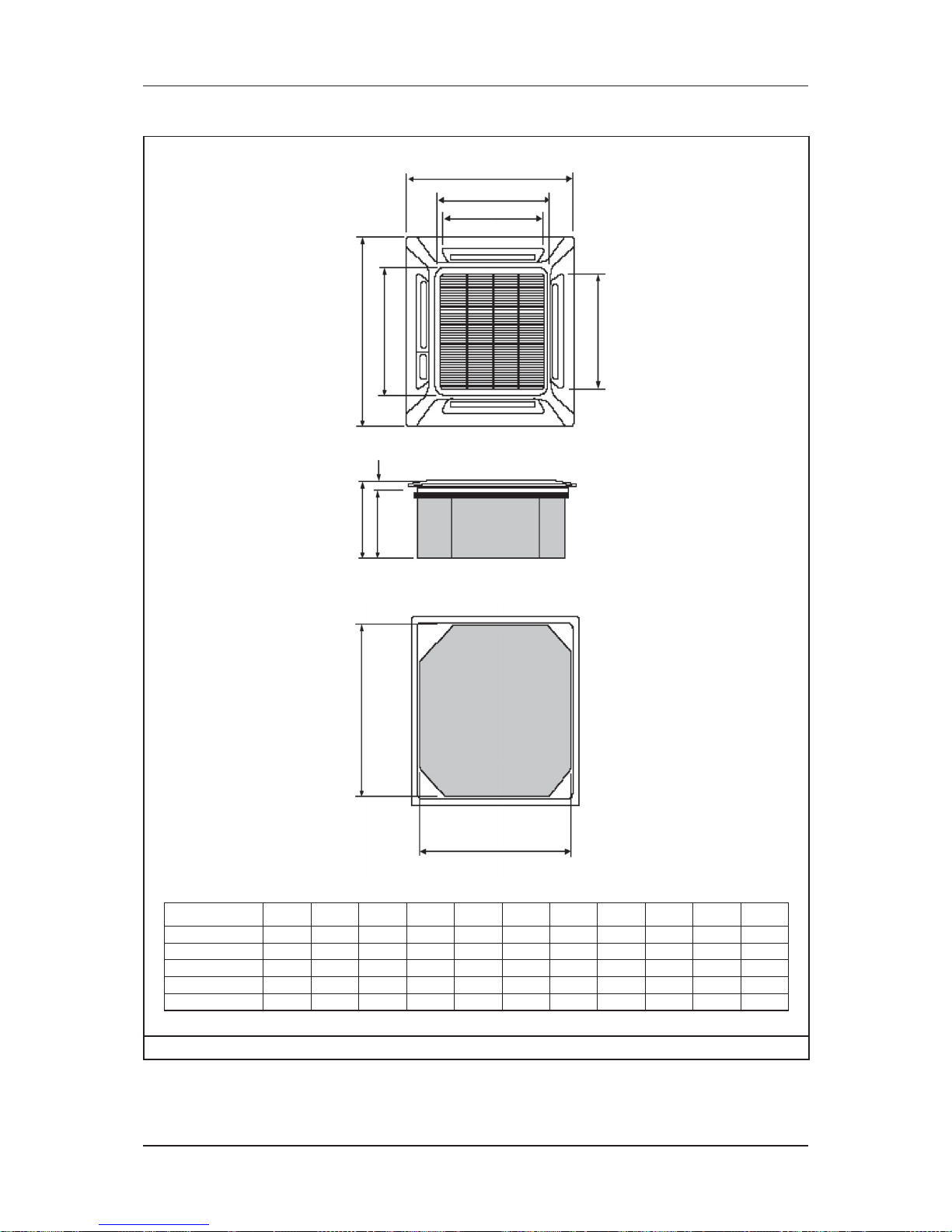
Outlines & Dimensions
73
Model: MCK20/25/30/40/50AWH
B
A
C
D
E
F
H
K
J
I
G
Model A B C D E F G H I J K
MCK20AWH 820 820 363 335 28 930 930 642 622 555 555
MCK25AWH 820 820 363 335 28 930 930 642 622 555 555
MCK30AWH 820 820 363 335 28 930 930 642 622 555 555
MCK40AWH 820 820 363 335 28 930 930 642 622 555 555
MCK50AWH 820 820 363 335 28 930 930 642 622 555 555
Note: Dimension in mm
Page 77

Outlines & Dimensions
74
Model: MCK010/015/020CW
Dimension
Model
ABCDEFGH I J K
MCK010CW/
MCK015CW/
MCK020CW
570 570 250 640 408 364 408 640 75 98 364
052075
408
640
408
364
364
SEE DETAIL A
DETAIL A
WATER INLET
WATER OUTLET
A
CB
D
E
F
G
H
K
I
J
Note: Dimension in mm
Page 78

Outlines & Dimensions
75
Model: MCK020/025/030/040/050EW
DETAIL A
SEE DETAIL A
WATER OUTLET
WATER INLET
820
820
63
363
335
28
158
113
930
642
555
555
930
622
Note: Dimension in mm
Page 79

Outlines & Dimensions
76
Model: MCM20/25/30/40/50DW
A
B
CGL
D
J
K
H H
I
F
E
M
343.0
100.2
N
O
Q
P
WATER OUTLET
WATER INLET
WATER OUTLET
WATER INLET
N
Q
P
DETAIL A
DETAIL B
SEE DETAIL A FOR CE20/25DW
SEE DETAIL B FOR CE30DW/40DW/50DW
Model A B C D E F G H I J K L M N O P Q
MCM20DW 1174 75 1082 68 58 156 1214 57 670 216 319 879 517 65 - 120 40
MCM25DW
1174 75 1082 68 58 156 1214 57 670 216 319 879 517 65 - 120 40
MCM30DW 1174 75 1082 68 93 156 1214 57 670 216 319 879 517 100 47 100 53
MCM40DW 1674 75 1582 68 93 156 1214 57 670 216 319 1379 517 95 40 100 45
MCM50DW 1674 75 1582 68 93 156 1214 57 670 216 319 1379 517 95 40 100 45
Note: Dimension in mm
Page 80

Outlines & Dimensions
77
Model: MCM15/20/25EW
20.0
20.0
1090.0
SEE DETAIL A
212.5
155.5
57.0
630.0
230.0
21.0
DRAIN PIPE
DETAIL A
143.6
6.6
01
800.0
+30.0
0.0
150.0
0.0
1
+
0.0
0.92
1
Note: Dimension in mm
Page 81
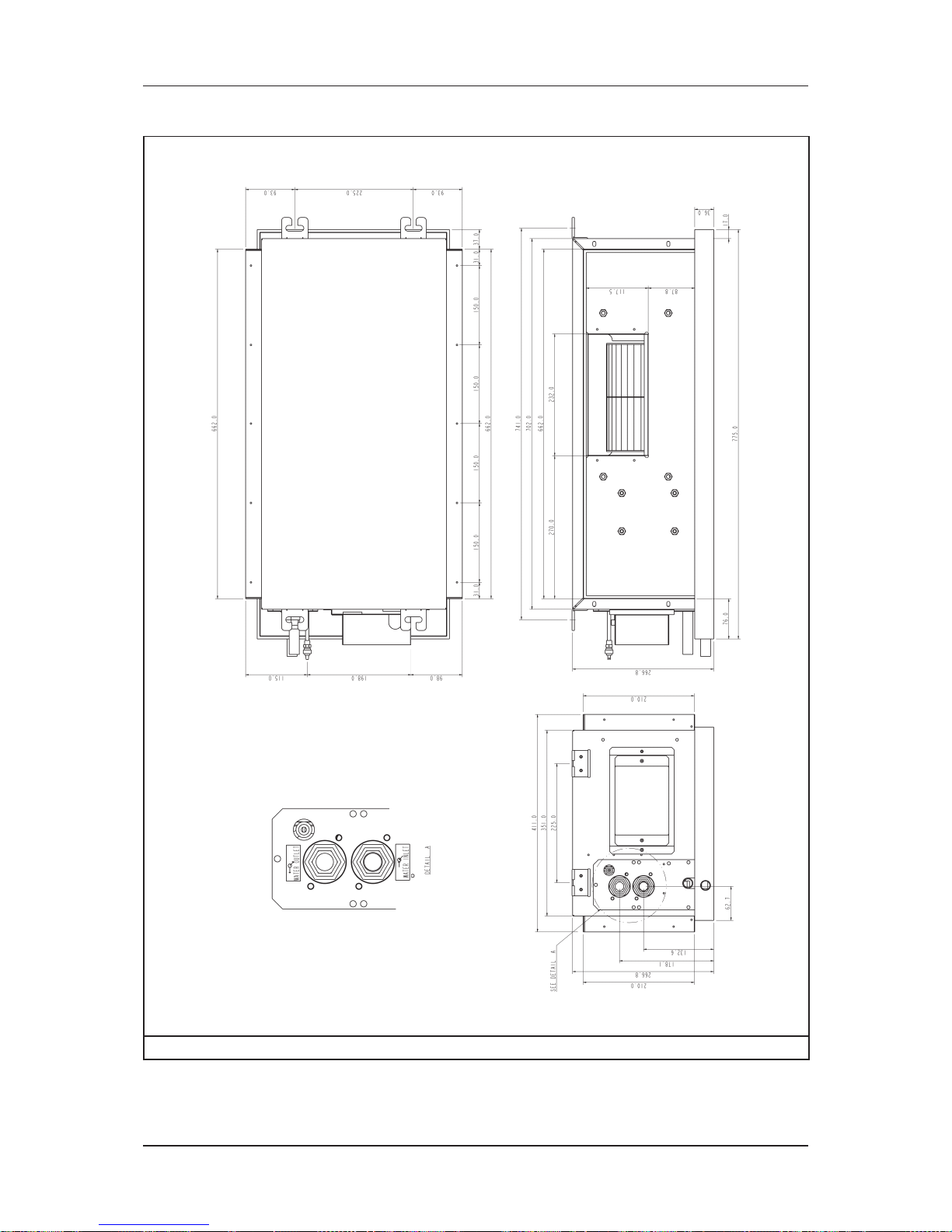
Outlines & Dimensions
78
Model: MCC010CW (Left Piping)
Note: Dimension in mm
Page 82

Outlines & Dimensions
79
Model: MCC010CW (Right Piping)
Note: Dimension in mm
Page 83
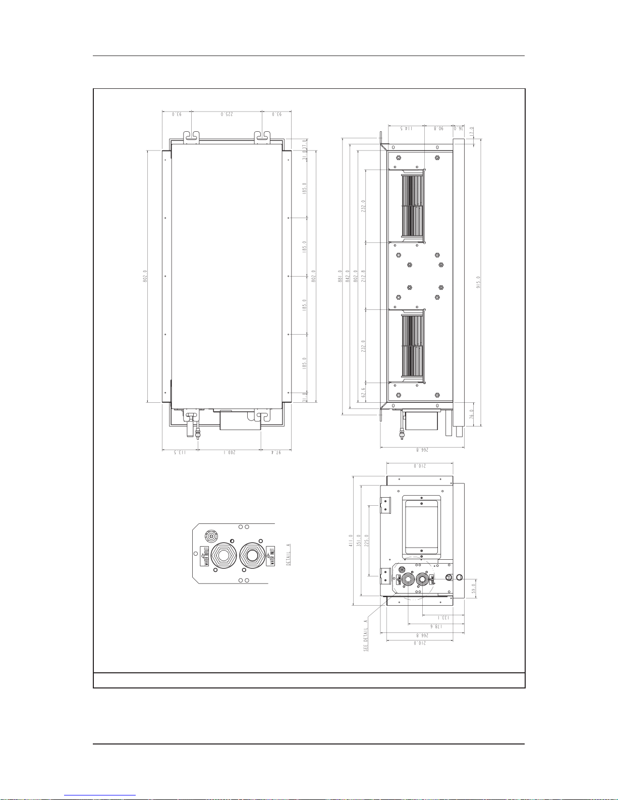
Outlines & Dimensions
80
Model: MCC015CW (Left Piping)
Note: Dimension in mm
Page 84

Outlines & Dimensions
81
Model: MCC015CW (Right Piping)
Note: Dimension in mm
Page 85

Outlines & Dimensions
82
Model: MCC020CW (Left Piping)
Note: Dimension in mm
Page 86
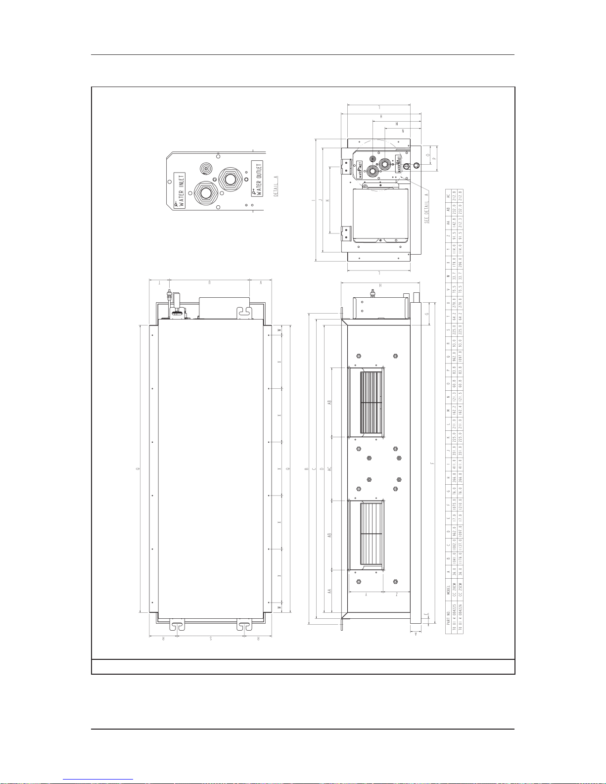
Outlines & Dimensions
83
Model: MCC020CW (Right Piping)
Note: Dimension in mm
Page 87

Outlines & Dimensions
84
Model: MCC025CW (Left Piping)
Note: Dimension in mm
Page 88

Outlines & Dimensions
85
Model: MCC025CW (Right Piping)
Note: Dimension in mm
Page 89

Outlines & Dimensions
86
Model: MCC028CW (Left Piping)
Note: Dimension in mm
Page 90

Outlines & Dimensions
87
Model: MCC028CW (Right Piping)
Note: Dimension in mm
Page 91
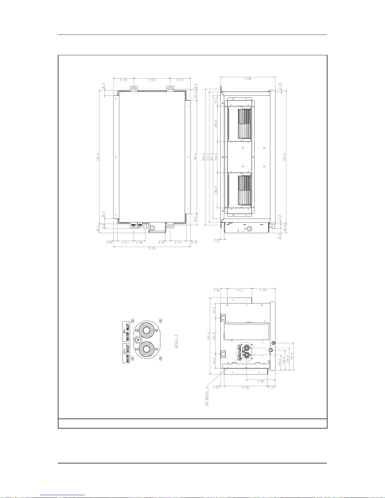
Outlines & Dimensions
88
Model: MCC030CW (Left Piping)
Note: Dimension in mm
Page 92
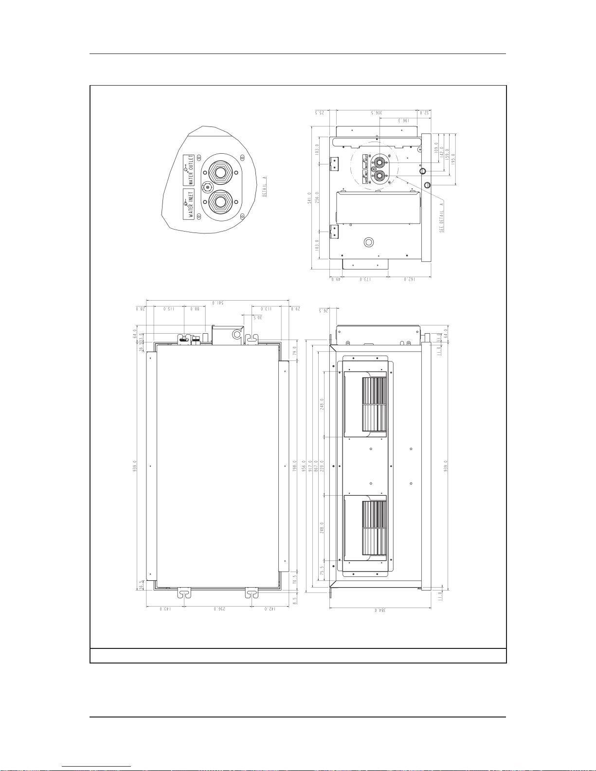
Outlines & Dimensions
89
Model: MCC030CW (Right Piping)
Note: Dimension in mm
Page 93

Outlines & Dimensions
90
Model: MCC038CW (Left Piping)
Note: Dimension in mm
Page 94

Outlines & Dimensions
91
Model: MCC038CW (Right Piping)
Note: Dimension in mm
Page 95

Outlines & Dimensions
92
Model: MCC040CW (Left Piping)
Note: Dimension in mm
Page 96

Outlines & Dimensions
93
Model: MCC040CW (Right Piping)
Note: Dimension in mm
Page 97

Outlines & Dimensions
94
Model: MCC050CW (Left Piping)
Note: Dimension in mm
Page 98
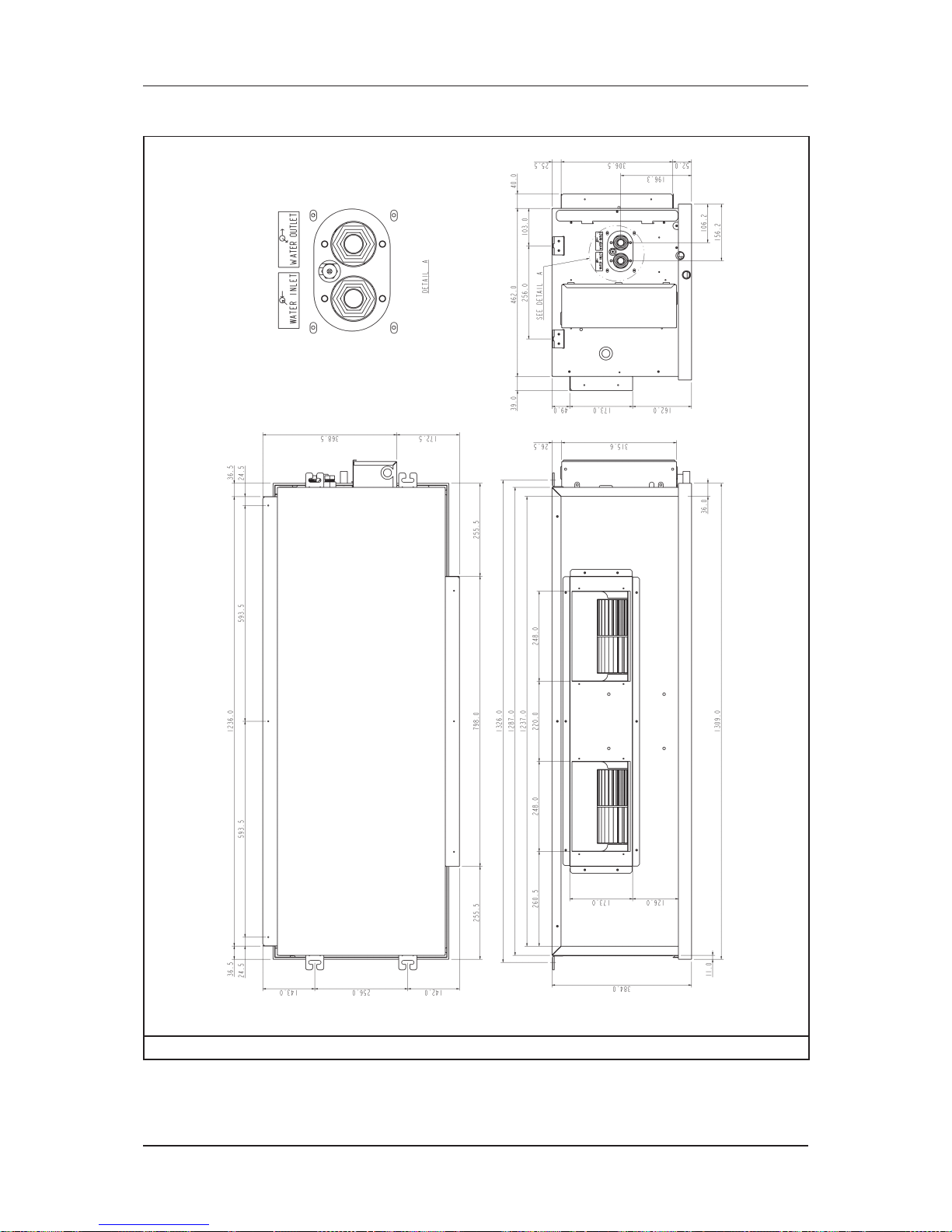
Outlines & Dimensions
95
Model: MCC050CW (Right Piping)
Note: Dimension in mm
Page 99

Outlines & Dimensions
96
Model: MCC060CW (Left Piping)
Note: Dimension in mm
Page 100

Outlines & Dimensions
97
Model: MCC060CW (Right Piping)
Note: Dimension in mm
 Loading...