

Page 1
Installation and Maintenance Manual
IM 704-3
Group: Controls
Part Number: IM 704-3
Date: November 2004
Supersedes: IM 704-2
MicroTech II Applied
TM
Rooftop Unit Controller and
Self-Contained Unit Controller
TM
BACnet
Use this manual to physically install the communications module into the unit and connect the unit to your
network. You also need the appropriate McQuay Engineering Data Sheet known as the Protocol Data Packet to
integrate the unit into your network. The Protocol Data Packet contains addressing details, BACnet® and
LonWorks® protocol information, and a list of the data points available to the network. See the Reference
Documents section of this document for part numbers of Protocol Data Packets. These documents are available
from your local McQuay International representative and for downloading at the McQuay International web site:
www.mcquay.com.
MSTP Communication Module
NOTICE
© 2004 McQuay International
Page 2

Table of Contents
Reference Documents ..........................................................................................................................................................2
General Information ............................................................................................................................................................3
Description ..........................................................................................................................................................................3
Application ..........................................................................................................................................................................4
Component Data ..................................................................................................................................................................4
Installation .........................................................................................................................................................................6
Mounting .............................................................................................................................................................................6
Mounting a new MicroTech II BACnet MSTP Communications Module on the Main Control Board ..............................6
Replacing a MicroTech II BACnet MSTP Communications Module on the
MicroTech II Main Control Board ......................................................................................................................................7
Integration ........................................................................................................................................................................12
Network Connection ..........................................................................................................................................................12
BACnet MSTP Network Addressing .................................................................................................................................12
Configuring the Unit Controller ........................................................................................................................................12
Service Information .........................................................................................................................................................14
Test Procedures .................................................................................................................................................................14
Replaceable Parts List .......................................................................................................................................................14
Network Connection Plug .................................................................................................................................................14
Kits and Wire Harness ......................................................................................................................................................14
Warranty ..........................................................................................................................................................................15
2 IM704-3
Page 3

Notice
© 2004 McQuay International, Minneapolis MN. All rights reserved throughout the world.
McQuay International reserves the right to change any information contained herein without prior notice. The user is
responsible for determining whether this product is appropriate for his or her application.
The following are trademarks or registered trademarks of their respective companies. Windows from Microsoft
Corporation; BACnet from ASHRAE; LONWORKS from Echelon Corporation; McQuay, MicroTech II from McQuay
International.
Reference Documents
Number Title Company Source
IM696 MicroTech II Applied Rooftop Unit Controller Installation
Manual
OM137 MicroTech II Applied Rooftop Discharge Air Controller
Operation Manual
OM138 MicroTech II Applied Rooftop Space Comfort Controller
Operation Manual
IM710 MicroTech II Verti cal Self-Contained Unit Controller
Installation Manual
OM711 MicroTech II Vertica l Self-Contained Dis charge Air
Controller Operation Manual
OM712 MicroTech II Vertical Self-Contained Sp ace Comfort
Controller Operation Manual
ED15060 MicroTech II Protocol Inf orm ation Data for McQuay
International Applied Rooftop Units
ED15061 MicroTech II Protocol Inf orm ation Data for McQuay
International Self-Contained Units
078-0014-01E LonMark Layers 1-6 Interoperability Guidelines, Version
3.0
078-0120-01E LonMark Application Layer Interoperability Guidelines,
Version 3.2
8500_10 LonMark Functiona l Profile: Space Comfort Controller,
Version 1.0
8610_10 LonMark Functional Profile: Discharge Air Controller,
Version
078-0156-01G LonWorks FTT-10A Free Topology Transceiver Users
Guide
McQuay International www.mcquay.com
McQuay International www.mcquay.com
McQuay International www.mcquay.com
McQuay International www.mcquay.com
McQuay International www.mcquay.com
McQuay International www.mcquay.com
McQuay International www.mcquay.com
McQuay International www.mcquay.com
LonMark Interoperability Assoc. www.lonmark.org
LonMark Interoperability Assoc. www.lonmark.org
LonMark Interoperability Assoc. www.lonmark.org
LonMark Interoperability Assoc. www.lonmark.org
Echelon Corporation www.lonmark.org
IM704-3 3
Page 4

General Information
This manual contains the information you need to install the communication modules and incorporate it into the network,
and maintain it.
! WARNING
Electric shock hazard. Can cause personal injury or equipment damage.
This equipment must be properly grounded. Connections and service to the MicroTech II control panel must be
performed only by personnel who are knowledgeable in the operation of the equipment being controlled.
! CAUTION
Static sensitive components. Can cause equipment damage.
Discharge any static electrical charge by touching the bare metal inside the control panel before performing any
service work. Never unplug cables, circuit board terminal blocks, or power plugs while power is applied to the panel.
NOTICE
This equipment generates, uses and can radiate radio frequency energy and, if not installed and used in accordance
with this instruction manual, may cause interference to radio communications. It has been tested and found to comply
with the limits for a Class A digital device, pursuant to part 15 of the FCC rules. These limits are designed to provide
reasonable protection against harmful interference when the equipment is operated in a commercial environment.
Operation of this equipment in a residential area is likely to cause harmful interference in which case the user will be
required to correct the interference at his or her own expense. McQuay International disclaims any liability resulting
from any interference or for the correction thereof.
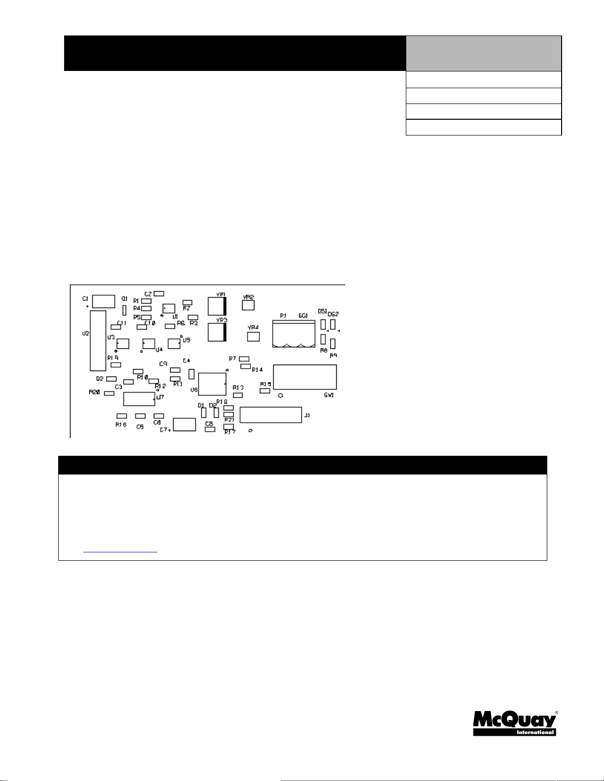
Description
A MicroTech II BACnet MSTP Communications Module incorporates a MicroTech II unit controller into a BACnet
MSTP Local Area Network (LAN). It is the interface to the Building Automation Network using BACnet objects.
The MicroTech II BACnet MSTP Communications Module is a printed circuit board that plugs onto the MicroTech II Main
Control Board. Figure 1 shows an outline drawing of the BACnet MSTP communications module.
Figure 1. BACnet MSTP Commun ic ations Modu le
IM704-3 4
Page 5
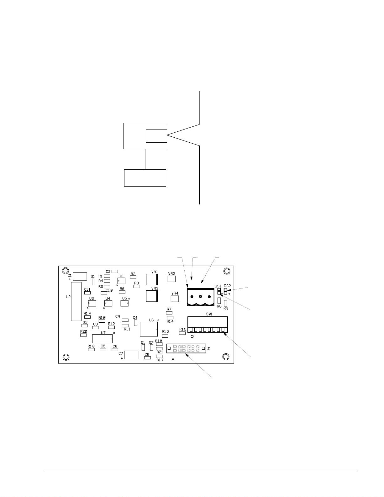
Application
The MicroTech II BACnet MSTP Communications Module connects the MicroTech II unit controller to the building
automation system (BAS) on a BACnet MSTP Local Area Network. It is the interface adapter for the exchange of BACnet
objects between the network and the unit controller. Figure 2 shows the communications module and unit controller
integrated into a BAS.
Figure 2. Building Automation Sys tem
BACnet MSTP
Network
MicroTech II
Main Control
Board
MicroTech II
Keypad
BACnet MSTP
Communications
Module
Component Data
Figure 3 shows the location of the major components of the communications module.
Figure 3. MicroTech II BACnet MSTP Communications Module Major Components
Network Connector Plug
+
P1
231
_
SG1
12 Pin Header
Transmit LED DS2
Receive LED DS1
Address Switch SW1
IM704-3 5
Page 6

Light Emitting Diodes (LEDs)
The MicroTech II BACnet MSTP Communications Module has two LEDs to indicate communication activity and status of
the communication module.
LED Function
DS1 Lights when the communications module is receiving data
DS2 Lights when the communications module is transmitting data
BACnet MSTP Network Connector (P1)
The P1 connector connects the MicroTech II BACnet MSTP Communications Module to the BACnet MSTP network.
Pin Designation Connection Function
1 REF TB2-130 Reference
2 N2- TB2-129 Inverting Input
3 N2+ TB2-128 Non-inverting Input
Address Switch
The Address Switch, SW1, must be set to the MAC address of the MicroTech II BACnet MSTP Communications Module.
The valid range is 0 to 127.
12-Pin Header
The 12-pin header, J1, connects the unit controller Main Control Board to the MicroTech II BACnet MSTP
Communications Module through the bottom of the communications module.
6 IM704-3
Page 7

Installation
The MicroTech II BACnet MSTP Communications Module can be installed in the field or it can be installed in the factory.
The module mounts on connector pins and is held in place with four plastic locking standoffs. The BACnet MSTP network
connects to the MicroTech II BACnet MSTP Communications Module at the network connector plug, P1. The BACnet
MSTP network cable connects TB2 in the unit cabinet.
Mounting
Mounting a new MicroTech II BACnet MSTP Communications Module on the Main Control Board
You can add a new MicroTech II BACnet MSTP Communications Module to the system in order to incorporate it into a
network. The MicroTech II BACnet MSTP Communications Module is included in a kit. The kit includes a cable harness
and this manual. See the Replacebale Parts list for item details and part numbers. You need the MAC address assigned to
the communications module. The network administrator can supply the MAC address.
To mount a new MicroTech II BACnet MSTP Communications Module on the MicroTech II Main Control Board
1. Remove power from the Main Control Board.
2. Remove the network cable plug-in connector terminal block in P1. See Figure 3.
3. Locate the empty connector and four standoffs for the MicroTech II BACnet MSTP Communications Module on the
Main Control Board. See Figure 4.
4. Orient the communications module printed circuit board so that the side with the components faces out and connector
pins can penetrate the 12-Pin Header on the communications module.
5. Push the communications module onto the connector pins and standoffs until you hear the faint click of the locking
standoffs securing the board in place.
6. For Applied Rooftop Units, connect the MicroTech II MSTP Communications Module to the network with wire
harness. See Figure 6.
a. Connect the cable harness clear wire (No. 522) to the N2+ terminal of the P1 connector plug and connect the black
wire (No. 523) to the N2– terminal of the P1 connector plug.
Note: You must maintain the polarity of the signal thro ughout the network. Always connect + to + and – to –.
b. Connect the cable harness drain wire (No. 524) to one of DRN terminals on TB6.
c. Route the cable harness down to the shelf below the main control board and to the left along the shelf to the edge.
Route the cable through a hole down the cable raceway to Terminal Block TB2. See Figure 7.
d. Connect the cable harness clear wire (No. 522) to terminal 128 of TB2 and connect the black wire (No. 523) to
terminal 129 of TB2.
Note: You must maintain the polarity of the signal thro ughout the network. Always connect + to + and – to –.
7. For Self-Contained Units, connect the MicroTech II MSTP Communications Module to the network with wire harness.
See Figure 6.
a. Connect the cable harness clear wire (No. 522) to the N2+ terminal of the P1 connector plug and connect the black
wire (No. 523) to the N2– terminal of the P1 connector plug.
b. Connect the cable harness drain wire (No. 524) to one of the DRN terminals on TB7.
Note: You must maintain the polarity of the signal throughout the network. Always connect + to + and – to –.
c. Route the cable harness down and over to your right along the main control board and up to Terminal Block TB 2.
See Figure 8.
d. Connect the cable harness clear wire (No. 522) to terminal 128 of TB2 and connect the black wire (No. 523) to
terminal 129 of TB2.
Note: You must maintain the polarity of the signal thro ughout the network. Always connect + to + and – to –.
8. Connect the BACnet MSTP network cable to TB 2 terminals 128, 129, and 130.
IM704-3 7
Page 8

Note: Terminal 130 of TB 2 is provided as a common connection point for the shield of the network cable. The shield
must be continuous throughout the entire network cable and must be connected to earth ground at one and only
one point.
Note: The BACnet MSTP network must be terminated at each end with a 120 ohm resistor between the + and -
terminals.
9. Set the Media Access Control (MAC) Address in Address Switch SW1. The network administrator assigns MAC
addresses. The valid range is 0 to 127.
10. Apply power to the MicroTech II Main Control Board.
Replacing a MicroTech II BACnet MSTP Communications Module on the MicroTech II Main Control Board
To replace the MicroTech II BACnet MSTP Communications Module on the Main Control Board
1. Remove power from the Main Control Board.
2. Record the MAC Address set in Address Switch SW1.
3. Remove the network cable plug in connector te rminal block P1. See Figure 3.
4. Locate the four standoffs for the MicroTech II BACnet MSTP Communications Module on the Main Control Board. See
Figure 4.
5. Use a pliers or screwdriver to depress the barb on one standoff and gently pull the corner of the communications module
over the barb. Be careful to not bend the communications module or misalign the connector pins.
6. Proceed to the other three corners, remove the communications module from each standoff, and pull the module over
the standoffs.
7. Gently lift the MicroTech II BACnet MSTP Communications Module from the Main Control Board.
8. Locate the empty connector pins and four standoffs for the MicroTech II BACnet MSTP Communications Module on
the Main Control Board. See Figure 4.
9. Orient the communications module so that the component side faces out and the connector pins can penetrate the 12-
Pin Header on the communications module. See Figure 5.
10. Push the MicroTech II BACnet MSTP Communications Module onto the connector pins and standoffs until you hear
the faint click of the locking standoffs securing the module in place.
11. Connect the communications module to the network. Replace network cable plug in P1. See Figure 3.
12. Reconnect the network to TB 2 terminals 128, 129, and 130 if it is necessary.
13. Set the Media Access Control (MAC) Address in Address Switch SW1. See Step 2.
14. Apply power to the MicroTech II Main Control Board.
8 IM704-3
Page 9

Figure 4. MSTP Communications Modul e Moun ted on the Ma in Contr o l Boar d
Main Control Board
Network Connector Plug
12-Pin Header
Location of Sta ndoff
(4 places)
IM704-3 9
Page 10

Figure 5. Mount BACnet MSTP Communications Module
A
12-Pin Header
BACnet MSTP
Communications Module
ddress Switch, SW1
Network Connector Plug
LED Indicators
Locking Stnadoff
Locking Standoff
(4 Places)
Figure 6. BACnet MSTP Connectio n Sch em atic Diagram
BACnet MSTP
Unit Terminal
Block TB2
128
129
130
Communication
DRN
Module
N2+
N2REF
TB6 (Applied Rooftop)
TB7 (Self-Contained)
10 IM704-3
Page 11

Figure 7. BACnet MSTP Network Cable Routing, Applied Rooftop Units
Controller
TB6
N2+
N2REF
BACnet
MSTP
Comm
Card
Network Cable
Cable Raceway
BACnet MSTP
Communications
Comunications
Module
Cable Shelf
Terminal Block TB2
IM704-3 11
Page 12

Figure 8. BACnet MSTP Network Cable Routi ng, Se lf-C o nta ine d Units
TB7
Controller
BACnet MSTP
Coomunications
Communications
Module
Terminal Block TB2
Network Ca ble Harness
12 IM704-3
Page 13

Integration
Network Connection
BACnet MSTP Network Addressing
The BACnet MSTP device address (Media Access Control [MAC] address) of the MicroTech II controller in a BACnet
Master Slave/Token Passing (MSTP) Local Area Network (LAN) is set in an eight-position dipswitch on the BACnet
MSTP Communications Module. See Figure 3. The address is physically set in eight binary switches. Bit 0 of the address
corresponds to switch position 1 and bit 7 of the address corresponds to switch position 8. All MicroTech II controllers must
be master controllers; therefore, bit 7 is always equal to 0 (open). An open switch (switch up) is a 0, and a closed switch
(switch down) is a 1. This address must be unique and is determined during installation. After you set the address in the
switches, you must cycle power (turn the controller off and then on again) to the controller in order for the new address to
take effect.
The receive LED flickers when the module is receiving data from the network, and the transmit LED flickers when the
module is sending data to the network. The default data transmission rate is set to 19,200 bps (baud). You can change the
data transmission rate to 9600 or 38,400 bps. Refer to the MicroTech II Protocol Data Information Packet (See Reference
Documents).
The default BACnet MSTP network address of the MicroTech II Unit Controller is 2001. You can change this address but it
must be the same as all other BACnet devices on the network for devices to communicate with each other. Refer to the
MicroTech II Protocol Data Information Packet (See Reference Documents).
Configuring the Unit Controller
All MicroTech II Main Control Boards for Rooftop and Self-contained units are loaded with software and configured at the
factory for stand-alone unit operation. The unit is ready to operate in a stand-alone manner with default set point parameters
that can be changed with the unit’s keypad/display or via a network signal. See the appropriate operation manual for the
default values and keypad/display operating instructions. See the appropriate MicroTech II Protocol Information Data for
descriptions of the available network variables. See Reference Documents for manual numbers.
There are 12 communication parameters involved in setting up the unit controller for proper communication with the
various communication module options (BACnet IP, BACnet MSTP or LON). These parameters are set differently by the
factory depending on which communication module is ordered and shipped with the unit. The table below lists the four
possible sets of default parameter settings. Not all the parameters apply to all the module options. The entries in the table
that are shown in bold font apply to a particular module option.
If unit is equipped with a factory installed BACnet MSTP communication module the controller is configured as shown in
the table. These parameters generally require field modification at the time of network commissioning. If a BACnet MSTP
module is added or a BACnet IP or LON module is removed and a BACnet MS/TP module is installed in the field, changes
to these parameters are required. Refer to the table to determine which parameters require change.
Note: The PC-based McQuay MicroTech II ServiceTools is required to modify these parameters.
IM704-3 13
Page 14

Table 1. Factory Communication Setup Parameter Settings
Parameter Name BACnet IP BACnet MSTP LON (DAC or SCC) No Communication
Module
lP Address
IP Subnet Mask
UDP Port Number
IP Router Address
IP Network Address
172.16.83.46
255.255.0.0
47808
172.16.128.01001
1001
MSTP Network Address 2001
MSTP MAC Address
1
129
MSTP Baud Rate 19200
Communication Option None
Device Instance Number
Max APDU Length
Device Object Name
2
3
4
XXXXXX XXXXXX
1024 501
MTll RTUC
XXXXXXXXX
or
MTII SCUC
XXXXXXXXX
172.16.83.46 172.16.83.46 172.16.83.46
255.255.0.0 255.255.0.0 255.255.0.0
47808 47808 47808
172.16128.0 172.16.128.0 172.16.128.0
1001 1001 1001
2001 2001
2 129
19200 19200
MSTP MSTP
2001
129
19200
MSTP
XXXXXX XXXXXX
501 501
MTll RTUC
XXXXXXXXX
or
MTII SCUC
XXXXXXXXX
MTll RTUC
XXXXXXXXX
or
MTII SCUC
XXXXXXXXX
MTll RTUC
XXXXXXXXX
or
MTII SCUC
XXXXXXXXX
Notes:
1. The MSTP MAC Address is not adjustable from the MicroTech II ServiceTools; it is set via the dip switch block on the
MSTP co mmunicatio n module.
2. The Device Instance Number is factory set equal to the last six significant digits of the 18 digit number on the barcode
label on the unit's main control board (MCB). For example if the last six digits are 043.066, then the Device Instance
Number is set to 43066. Whether or not this parameter is use by the controls integrator, it must be set to a unique value
from all other controllers in the network.
3. The Max APDU Length parameter should not be set higher than 1024 for BACnet IP or 501 for BACnet MSTP.
4. The Xs in Device Object Name are factory set equal to the last nine digits of the 18 digit number on the bar-code label on
the units main control board (MCB). For example if the last nine digits are 000.043.066, then the Device Object Name is
set to MTII RTUC 000043066 for an applied rooftop unit or MTII SCUC 000043066 for a vertical self-contained unit.
Whether or not this parameter is use by the controls integrator, it must be set to a unique value from all other controllers
in the network.
14 IM704-3
Page 15

Service Information
Test Procedures
If you can control the unit from the unit’s keypad, but you are not able to communicate with unit via the network:
• Verify the network (bus) wiring.
• Verify the cable harness to the network terminals.
• Verify that the Transmit LED (DS2) is flickering.
• Verify that the MSTP MAC address (SW1) is set in the 0-127 range (Master).
• Check the network communication parameters in the unit controller for prop e r settings. Refer to Configuring the
Unit Controller.
If the MicroTech II BACnet MSTP Communications Module still does not respond, replace the communications module.
Replaceable Parts List
Network Connection Plug
Generic Replacement Parts
The three-contact network connector plug has custom markings, but if you lose this terminal block you can replace it with a
standard block without the markings from a manufacturer. The list below contains manufacturers part numbers for
equivalent p arts without the custom markings
You can order direct replacement parts from McQuay International (1-800-37-PARTS).
Manufacturer Telephone Order Number
Phoenix Contact (800) 888-7388 17 57 02 2
Altech Corp (908) 806-9400 37.003
Direct Replacement Parts
Part Number Description
AP-TBN3COM-0 10 terminal blocks marked LON A, LON B, and SHIELD
AS-TBKIT-0 5 terminal blocks marked REF, N2- and N2+ and
5 terminal block marked 24VAC, COM and ZBUS
Kits and Wire Harness
Component Description Part No.
Kit, MSTP Installation Kit for BACnet MSTP Communications Module 090016702
Wire Harness Wire harness for LonMark Communications Modules 090011182
IM704-3 15
Page 16

Warranty
Consult your local McQuay Representative for warranty details. Refer to Form 933-43285Y. To find your local McQuay
Representative, go to www.mcquay.com.
Warranty Return Material Procedure
Defective material may not be returned without permission of authorized factory service personnel of McQuay International
in Minneapolis, Minnesota, (763) 553-5330. A "Return Goods" tag must be included with the returned material. Enter the
required information to expedite handling and prompt issuance of credits. All parts must be returned to the app r opriate
McQuay facility, designated on the "Return Goods" tag. Transportation charges must be prepaid.
The return of the part does not constitute an order for replacement. Therefore, a purchase order must be entered through the
nearest McQuay representative. The order should include part number, model number, and serial number of the unit
involved.
Credit will be issued on customer's purchase order following an inspection of the return part and upon determination that the
failure is due to faulty material or workmanship during the warranty period.
Replacement Parts
When writing to McQuay for service or replacement parts, refer to the model number and serial number of the unit as
stamped on the serial plate attached to the unit. If replacement parts are required, mention the date of installation of the unit
and date of failure, along with an explanation of the malfunctions and a description of the replacement parts required.
This document contains the most current product information as of this printing. For the most current product
information, please go to www.mcquay.com.
© 2004 McQuay International • www.mcquay.com • 800-432-1342
16 IM704-3
 Loading...