

Page 1
Operation and Maintenance Manual OM 844-1
Group: Rooftop Systems
Part Number: OM 844
Date: January 2007
MD2 Variable Speed Drive Controllers
Packaged Rooftop Units RPS, RFS, RDT, RPE, and RDE
Rooftop Air Handler Units RDS and RAH
Vertical Self-Contained Units SWP and SWT
Commercial Packaged Rooftop Units MPS 030 to 050 Tons
© 2007 McQuay International
Page 2

Introduction.................................................................... 3
Applications With MicroTech II Control (A1a, A2, B1a,
B2, C, and D)............................................................ 4
Applications Without MicroTech II Controls (A1b and
B1b).......................................................................... 4
Replacement VFD .................................................... 4
Hazard Categories and Special Symbols ...................... 5
Before You Begin .......................................................... 6
Bus Voltage Measurement Procedure ..................... 7
Initial Start-Up........................................................... 8
Control Terminals .......................................................... 9
Switch Settings and Terminal Designations ................ 12
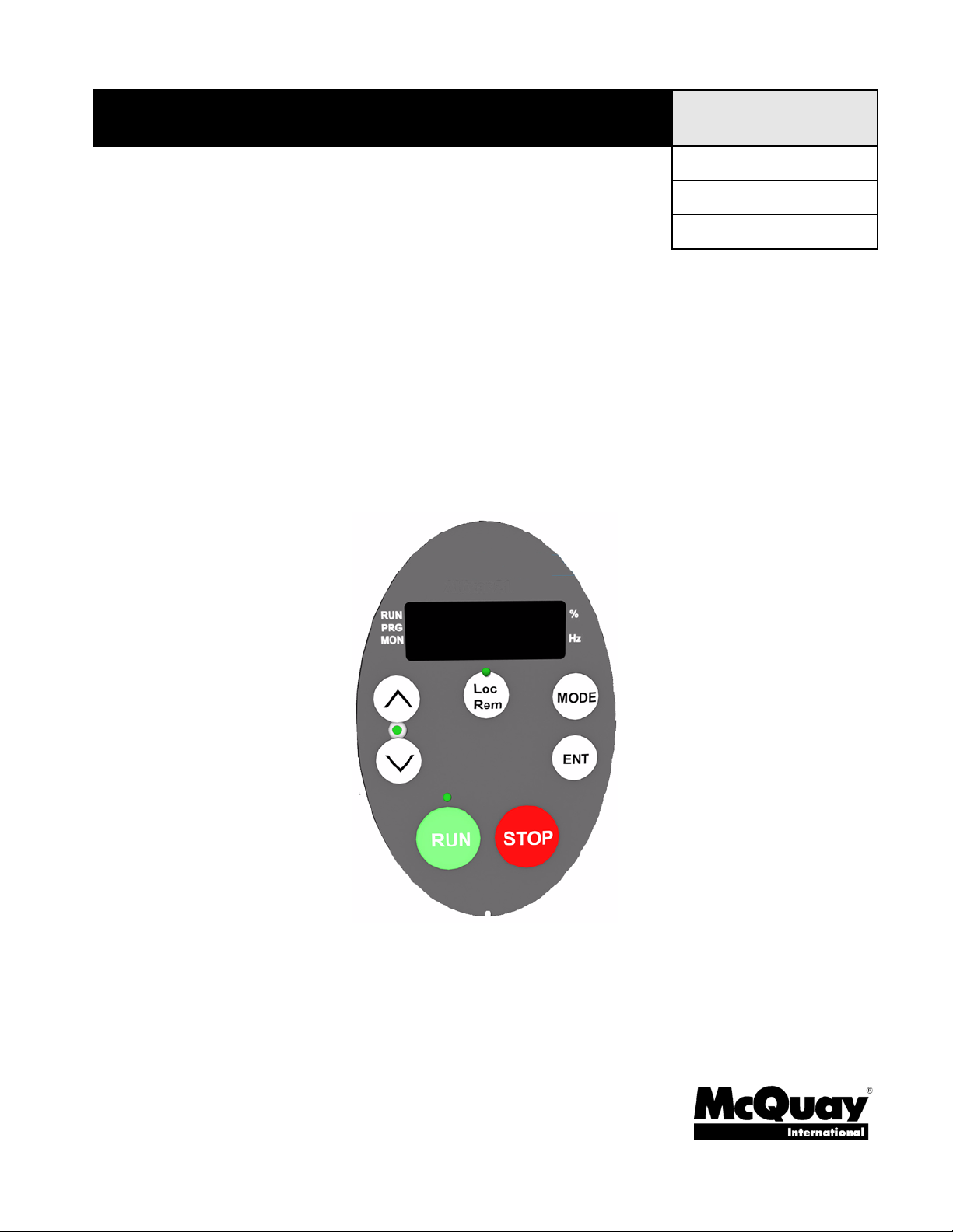
Integrated Display Terminal......................................... 13
Programming ............................................................... 15
Mode Access.......................................................... 15
Parameter Groups.................................................. 15
Access to Menus and Parameters ......................... 16
AUF Quick Menu....................................................... 17
AUF Quick Menu Parameters .............................. 18
Setting the Acceleration/Deceleration
Ramp Times ........................................................... 19
Setting the Macro Function .................................... 20
Setting the Mode of Operation ............................... 20
Command Mode Selection ..................................... 21
Frequency Mode Selection..................................... 21
Default Setting........................................................ 22
Forward/Reverse Run Selection ............................ 22
Maximum Frequency.............................................. 23
High Speed and Low Speed................................... 24
Nominal Motor Frequency and Voltage
Settings .................................................................. 24
V/Hz Control Mode Selection ................................. 25
Voltage Boost (Energy Recovery
Application Only) .................................................... 25
Electronic Motor Overload Protection..................... 26
Input Signal Selection ............................................ 28
Terminal Function Selection................................... 28
Jump Frequency (Jumping
Resonant Frequencies).......................................... 29
Switching Frequency.............................................. 30
Auto Restart ........................................................... 31
Drive Controller Fault Retention............................. 33
Output Phase Loss Detection ................................ 33
Input Phase Loss Detection ................................... 34
Avoiding Overvoltage Tripping ............................... 34
Undervoltage Fault................................................. 35
Changing the Display Parameter ........................... 36
Troubleshooting Fault and Alarm Codes..................... 37
Resetting the Drive Controller After a
Fault Condition ....................................................... 44
Appendix A—Input Terminal Functions....................... 45
Appendix B—Output Terminal Functions .................... 49
Appendix C—Receiving and Preliminary Inspection... 53
Storing and Shipping.............................................. 53
Lifting and Handling ............................................... 54
Precautions ............................................................ 54
Appendix D—Wiring Recommendations ..................... 60
Power Terminals .................................................... 63
Appendix E—Wiring Diagrams and
Parameter Settings...................................................... 65
LL (Lower Limit Frequency) ................................... 65
MODE KEY (LOCAL or REMOTE Keypad) ........... 65
MPS Rooftop with MicroTech II Controls for SAF and
EAF Applications.................................................... 66
Rooftop and Self-Contained with MicroTech II Controls
for SAF, RAF, and EAF Applications ..................... 69
Rooftop Controls by Others for SAF, RAF, and EAF
Applications............................................................ 72
Rooftop Energy Recovery Wheel Speed Control... 74
Page 3

Introduction
Introduction
This manual provides information about the McQuay MD2 variable speed drive (VFD)
that was originally factory installed within a McQuay HVAC unit. The manual
describes operation of the VFD along with descriptions and functions of the VFD
parameters for the models and applications listed below.
Specific packaged equipment wiring schematics and parameter settings can be found
in Appendix E—Wiring Diagrams and Parameter Settings on page 65. Please refer to
the rooftop or self-contained installation manual and/or operation manual for
information on the unit controller and its control of the variable speed drive.
A. Packaged Rooftop models RPS, RFS, RDT, RPE, and RDE
1. VFDs for supply, return and exhaust air fan speed control
a. Units with Mircotech II control
b. Units without Microtech II control
2. VFDs for energy recovery wheel speed control
B. Rooftop Air Handler models RDS and RAH
1. VFDs for supply, return and exhaust air fan speed control
a. Units with Mircotech II control
b. Units without Microtech II control
2. VFDs for energy recovery wheel speed control
C. Vertical Self-Contained models SWP and SWT, supply fan speed control
D. Commercial Packaged Rooftop Model MPS
1. For supply and exhaust air fan speed control
WARNING
UNINTENDED EQUIPMENT OPERATION
• Modifying or changing parameters whose function is not
described in this manual will affect drive controller operation.
Some register changes will take effect as soon as they are
entered.
• Do not modify or change parameters whose function is not
described in this instruction bulletin.
Failure to follow this instruction can result in death, serious
injury, or equipment damage.
McQuay OM 844-1 3
Page 4

Introduction
Applications With MicroTech II Control (A1a, A2, B1a, B2, C, and D)
The variable speed drive has been selected and coordinated with the McQuay air
conditioning equipment’s unit controller. The drive that is installed on the McQuay
packaged equipment has the parameters modified for the HVAC application. For the
standard HVAC system design, no further modifications should need to be made to
the drive.
Applications Without MicroTech II Controls (A1b and B1b)
The McQuay variable speed drive parameters must be changed to coordinate the
drive with the unit controls and the system it is being installed on. This manual
describes the parameters that should be reviewed and adjusted. Other parameters
should not be adjusted.
Replacement VFD
When replacing a VFD, the owner/installer must determine which of the above listed
applications applies and follow the appropriate procedures within this manual.
4 McQuay OM 844-1
Page 5
Hazard Categories and Special Symbols
Hazard Categories and Special Symbols
Read these instructions carefully and look at the equipment to become familiar with
the device before trying to install, operate, service, or maintain it. The following special
messages may appear throughout this bulletin or on the equipment to warn of
potential hazards or to call attention to information that clarifies or simplifies a
procedure.
The addition of a lightning bolt or ANSI man symbol to a “Danger” or “Warning” safety
label indicates that an electrical hazard exists which will result in personal injury if the
instructions are not followed.
The exclamation point symbol is used to alert you to potential personal injury hazards.
Obey all safety messages that follow this symbol to avoid possible injury or death.
Symbol Name
Lightning Bolt
ANSI Man
Exclamation Point
DANGER
DANGER indicates an imminently hazardous situation which, if not
avoided, will result in death or serious injury.
WARNING
WARNING indicates a potentially hazardous situation which, if not
avoided, can result in death, serious injury, or equipment damage.
CAUTION
CAUTION indicates a potentially hazardous situation which, if not
avoided, can result in minor or moderate injury.
CAUTION
CAUTION, used without the safety alert symbol, indicates a
potentially hazardous situation which, if not avoided, can result in
property damage.
McQuay OM 844-1 5
Page 6
Before You Begin
Before You Begin
Read and understand these instructions before performing any procedure on this
drive controller.
DANGER
HAZARDOUS VOLTAGE
• Read and understand this manual before installing or operating
the MD2 drive controller. Installation, adjustment, repair, and
maintenance must be performed by qualified personnel.
• The user is responsible for compliance with all international and
national electrical code requirements with respect to grounding of
all equipment.
• Many parts of this drive controller, including the printed circuit
boards, operate at the line voltage. DO NOT TOUCH. Use only
electrically insulated tools.
• Before servicing the drive controller:
— Disconnect all power.
— Place a “DO NOT TURN ON” label on all power disconnects.
— Lock all power disconnects in the open/off position.
• DO NOT touch unshielded components or terminal strip screw
connections with voltage present.
• DO NOT short across terminals PA/+ and PC/- or across the DC
bus capacitors.
• Install and close all covers before applying power or starting and
stopping the drive controller.
• Disconnect all power, including external control power that may
be present, before servicing the drive controller. WAIT
10 MINUTES to allow the DC bus capacitors to discharge. Then
follow the DC bus voltage measurement procedure on page 7 to
verify that the DC voltage is less than 45 V. The drive LEDs are
not accurate indicators of the absence of DC bus voltage.
Failure to follow these instructions will result in death or
serious injury.
CAUTION
IMPROPER DRIVE CONTROLLER OPERATION
• If the drive controller is de-energized for a prolonged period, the
performance of the electrolytic capacitors will be reduced.
• Once a year, apply power to the drive controller for at least
5 hours to restore the performance of the capacitors, then check
its operation.
• If the drive has not been powered for more than a year, do not
connect the drive controller to the line voltage. Gradually
increase the voltage using an adjustable AC source.
Failure to follow these instructions can result in injury and
equipment damage.
6 McQuay OM 844-1
Page 7
Before You Begin
DANGER
AUTOMATIC RESTART ENABLED
• This drive controller can restart under fault conditions.
• Equipment must be shut down, locked out and tagged out to
perform servicing or maintenance.
Failure to follow this instruction will result in death or serious
injury.
Bus Voltage Measurement Procedure
Before working on the drive controller, turn it off and wait 10 minutes to allow the DC
bus to discharge and then measure the DC bus voltage.
DANGER
HAZARDOUS VOLTAGE
Read and understand the precautions in “Before You Begin” on
page 6 before performing this procedure.
Failure to follow this instruction will result in death or serious
injury.
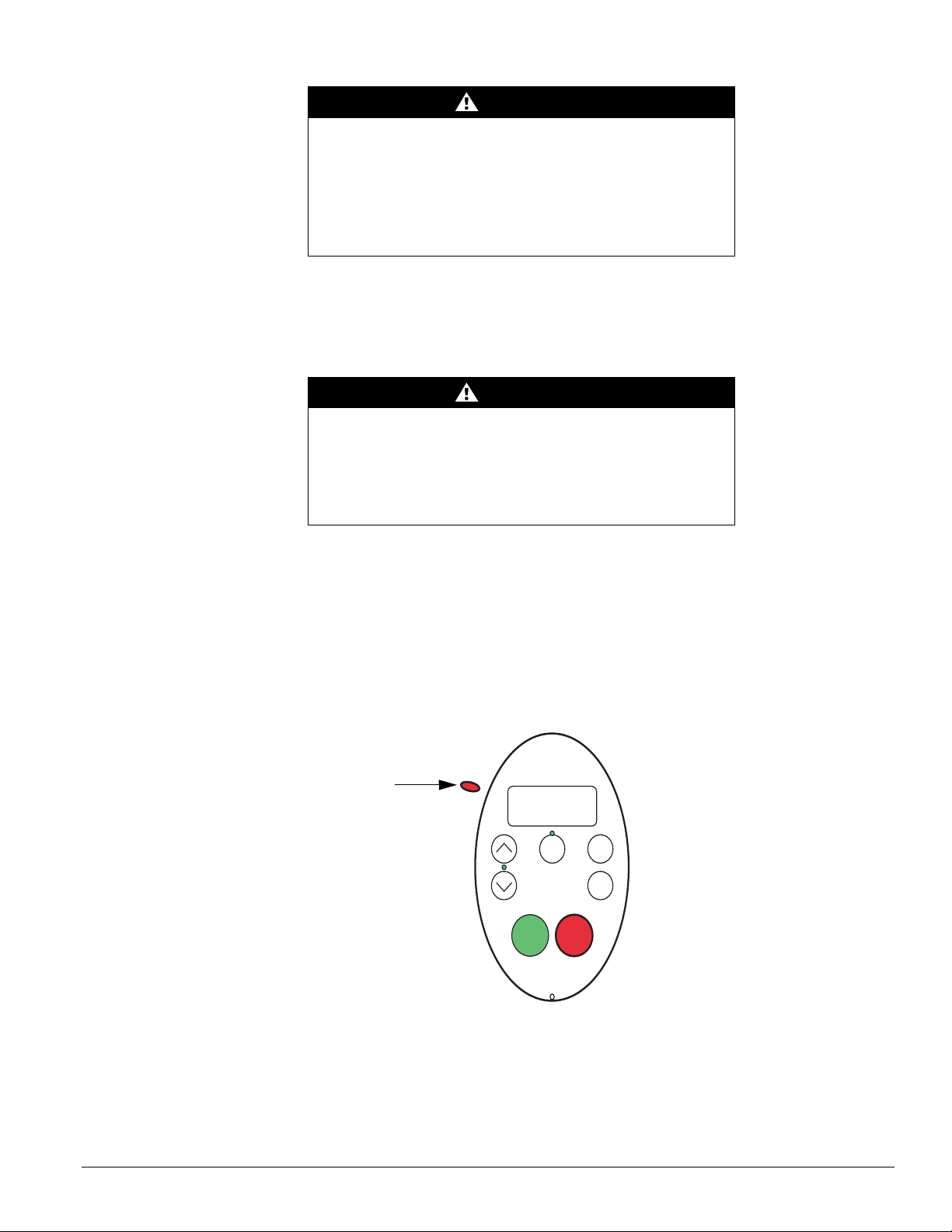
The DC bus voltage can exceed 1,000 Vdc. Use a properly rated voltage-sensing
device when performing this procedure. To measure the DC bus voltage:
1. Disconnect all power and wait 10 minutes to allow the DC bus to discharge.
2. Measure the voltage of the DC bus between the PA/+ and PC/– terminals to
ensure that the voltage is less than 45 Vdc.
3. If the DC bus capacitors do not discharge completely, contact your local McQuay
representative. Do not repair or operate the drive controller.
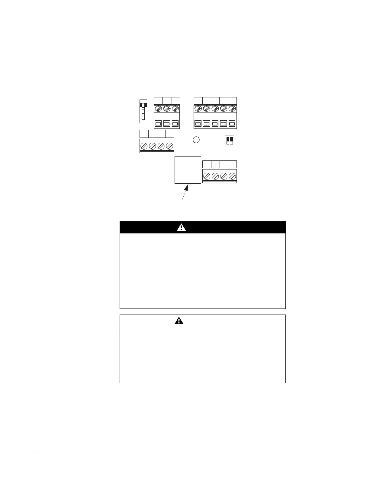
Figure 1: Capacitor Charging LED
Capacitor
charging LED
RUN
PRG
MON
RUN STOP
Loc
Rem
%
Hz
MODE
ENT
McQuay OM 844-1 7
Page 8

Before You Begin
Initial Start-Up
Before providing power to the VFD, refer to the appropriate unit
installation/maintenance manual(s) listed below:
• IM 738 for packaged rooftops with air-cooled condensers (RPS, RFS, and RDT)
• IM 487 for rooftop air handlers (RDS and RAH)
• IM 791 for packaged rooftops with evaporative condensers (RPE and RDE)
• IM 708 for one-piece self-contained units
• IM 709 for modular self-contained units
Perform the following (RPS/RDT example) general procedures on the specific unit
purchased (yours may differ slightly depending on the unit)
1. Before closing (connecting) the power disconnect switch, open (disconnect) the
following unit control circuit switches:
a. Turn system switch S1 to OFF
b. Turn system switch S7 to OFF
2. Confirm duct static pressure sensor SPS1 is connected to the ductwork.
3. Confirm the VFD lugs for the line voltage are tight.
4. Confirm the horsepower (hp) of the drive matches that of the motor.
Before starting the fan and VFD
1. Close the unit disconnect switch. With the control system switch S1 in the OFF
position, power should be available only to the control circuit transformer (TI) and
the compressor crankcase heaters.
2. Turn the Switch S1 to ON. Power should now be supplied to the control panel, and
the LEDs on MCB1 should follow the normal startup sequence (refer to the “MCB
LED Power-Up Sequence” of IM 696).
3. Verify all duct isolation dampers are open. Unit mounted isolation dampers may be
mounted in the supply or return sections.
4. Place the unit into the “Fan Only” mode through the keypad menu System
Summary\System\Ctrl Mode= Fan Only.
5. Confirm the power supply matches the setting of the J7J parameter.
6. Confirm the power supply frequency matches that of the J7 parameter.
7. Confirm the thermal protection level, tHr (or amps), matches that of the motor.
NOTE: All of the above parameters can be quickly found in the AUF Quick menu.
Start the fan and VFD
1. Turn Switch S7 to ON. The controller should enter the “Startup Initial” operating
state. If the fan does not run:
a. Check fuses F1 and F3.
b. Check that the manual motor protectors or circuit breakers have not tripped.
c. Check the optional phase monitor.
2. If the fans are equipped with optional spring isolators, check the fan spring mount
adjustment. When the fans are running they should be level.
3. Verify the rotation is correct.
4. Verify the DHL safety is opening at a pressure compatible with duct working
pressure limits.
NOTE: Refer to the unit IMs for additional non-VFD instructions.
8 McQuay OM 844-1
Page 9
Control Terminals
Control Terminals
The control terminals are illustrated in Figure 2 (refer to Appendix E—Wiring
Diagrams and Parameter Settings for more details).
Figure 2: Control Terminals
SOURCE
PLC
SINK
SW4
PLC
P24 CC
SW4
F R RES FM
Connector (RJ45)
FLA FLB FLC R Y RC
FM VIA
VIV
SW2 SW3
PP VIA VIB CC
Factory settings:
SW4:
FM: V side
VIA: V side
•
I
• Tightening torque: 0.6 Nm
SOURCE side
(positive)
Maximum wire size: 2.5 mm²
(AWG 14)
(5.3 lb.in)
DANGER
UNINTENDED EQUIPMENT OPERATION
• The accidental grounding of logic inputs configured for Sink Logic
can result in unintended activation of drive controller functions.
• Protect the signal conductors against damage that could result in
unintentional conductor grounding.
• Follow NFPA 79 and EN 60204 guidelines for proper control
circuit grounding practices.
Failure to follow these instructions will result in death or
serious injury.
WARNING
RISK OF IMPROPER OPERATION
The MD2 logic input selector switch (SW4) is factory-set to the
source position. The switch should never be moved to the PLC or
sink position.
Failure to follow this instruction can result in death or serious
injury.
McQuay OM 844-1 9
Page 10
Control Terminals
Table 1: Control Terminal Characteristics
Terminals Function Characteristics
External
PLC
power supply
input
P24
Internal
supply
CC Common 0 V common (2 terminals)
FLA,
FLB,
FLC
Configurable
relay outputs
RY, RC
F
R
Logic inputs
RES
FM
Analog
output
Internal
PP
supply
available
+24 Vdc input for external power supply for logic inputs
Max. permissible voltage: 50 Vac
Short-circuit and overload protection:
24 Vdc supply (min. 21 V, max. 27 V), maximum current:
200 mA
One relay logic output, one N/C contact, and one N/O contact
with common point
Minimum switching capacity: 3 mA for 24
Maximum switching capacity:
• On resistive load: 5 A for 250 Vac or 30
• On inductive load: 2 A for 250 Vac or 30
Max. response time: 7ms ± 0.5ms
Electrical service life: 100,000 operations
One relay logic output, one N/O contact
Minimum switching capacity: 3 mA for 24
Maximum switching capacity:
• On resistive load: 5 A for 250 Vac or 30
• On inductive load: 2 A for 250 Vac or 30
Max. response time: 7ms ± 0.5ms
Electrical service life: 100,000 operations
Three programmable logic inputs, 24
level 1 PLC, IEC 65A-68 standard
Impedance: 3.5 kΩ
Maximum voltage: 30 V
Max. sampling time: 2 ms ± 0.5 ms
Multiple assignment makes it possible to configure several
functions on one input
Positive logic (Source): State 0 if ≤ 5 V or logic input not wired,
state 1 if ≥ 11 V
Negative logic (Sink): State 0 if ≥ 16 V or logic input not wired,
state 1 if ≤ 10 V
One switch-configurable voltage or current analog output:
• Voltage analog output 0–10 Vdc, minimum load impedance 470 Ω
• Current analog output X–Y mA by programming X and Y from 0 to
20 mA, maximum load impedance: 500 Ω
Max. sampling time: 2 ms ± 0.5 ms
Resolution: 10 bits
Accuracy: ± 1% for a temperature variation of 60°C
Linearity: ± 0.2%
Short-circuit and overload protection:
One 10.5 Vdc ± 5% supply for the reference potentiometer (1
to 10 kΩ), maximum current: 10 mA
Vdc
Vdc
Vdc
Vdc
Vdc
Vdc
Vdc
, compatible with
10 McQuay OM 844-1
Page 11

Table 1: Control Terminal Characteristics (continued)
Terminals Function Characteristics
Switch-configurable voltage or current analog input:
• Voltage analog input 0–10 Vdc, impedance 30 kΩ (max. safe
voltage: 27 Vdc +/- 3 Vdc)
• Analog current input X–Y mA by programming X and Y from 0 to
20 mA, with impedance 242 Ω
Max. sampling time: 2 ms ± 0.5 ms
Resolution: 11 bits
Accuracy: ± 0.6% for a temperature variation of 60°C
Linearity: ± 0.15% of the maximum value
•
0–10
Vdc
, impedance 30 kΩ (max. safe voltage 27 Vdc)
• Max. sampling time: 2 ms ± 0.5 ms
• Resolution: 11 bits
• Accuracy: ± 0.6% for a temperature variation of 60°C
• Linearity: ± 0.15% of the maximum value
VIA
VIB
Analog/logic
input
Analog input Voltage analog input:
Control Terminals
McQuay OM 844-1 11
Page 12
Switch Settings and Terminal Designations
Switch Settings and Terminal Designations
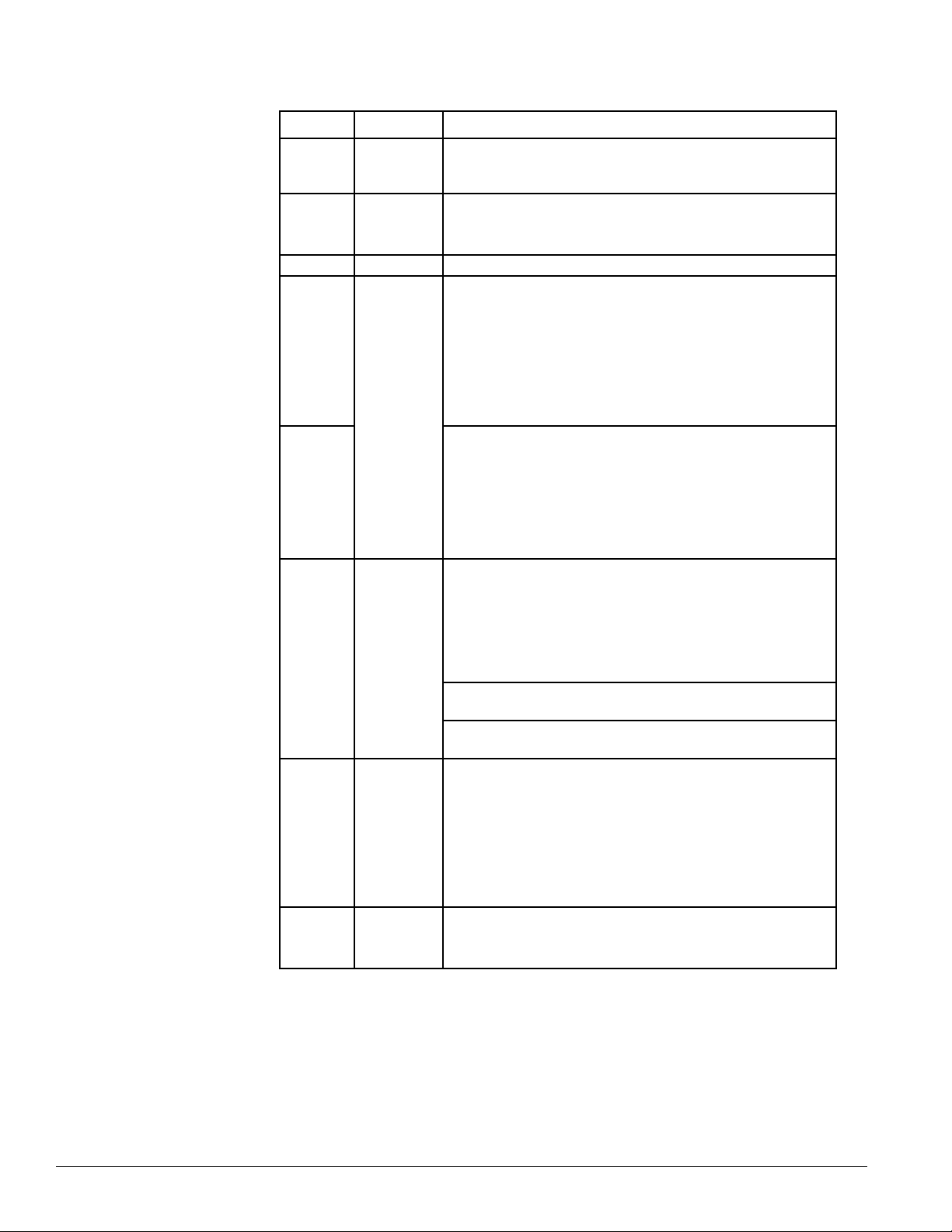
Figure 3: Switches
Voltage/current selection for
analog I/O (FM and VIA)
SW4
Source
(positive logic)
PLC
Sink
(negative logic)
SW4
V (voltage)
Selection of logic
type
FM VIA
V (voltage)
I (current)I (current)
SW2 SW3
NOTE: Refer to Appendix E—Wiring Diagrams and Parameter Settings on page 65 for your
specific HVAC application and switch settings.
NOTE: The logic input switch SW4 is set to the source position. The switch should never be
moved to the PLC or sink position.
DANGER
UNINTENDED EQUIPMENT OPERATION
• The accidental grounding of logic inputs configured for Sink Logic
can result in unintended activation of drive controller functions.
• Protect the signal conductors against damage that could result in
unintentional conductor grounding.
• Follow NFPA 79 and EN 60204 guidelines for proper control
circuit grounding practices.
Failure to follow these instructions will result in death or
serious injury.
Table 2: Drive Controller Default Terminal Function Assignments
Terminal Function
FLA-FLB-FLC relay
RY-RC relay
F Forward (2-wire control)
R Preset speed
RES Fault reset
VIA Speed reference 0-10 Vdc
VIB Not assigned
FM Output frequency
De-energized in the event of a fault or when the power supply
is disconnected
Energized when the speed is greater than or equal to low
speed (LL)
12 McQuay OM 844-1
Page 13
Integrated Display Terminal
Integrated Display Terminal
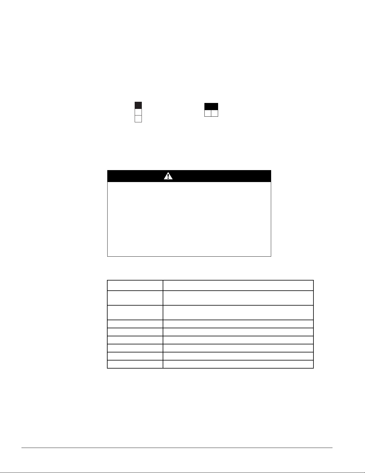
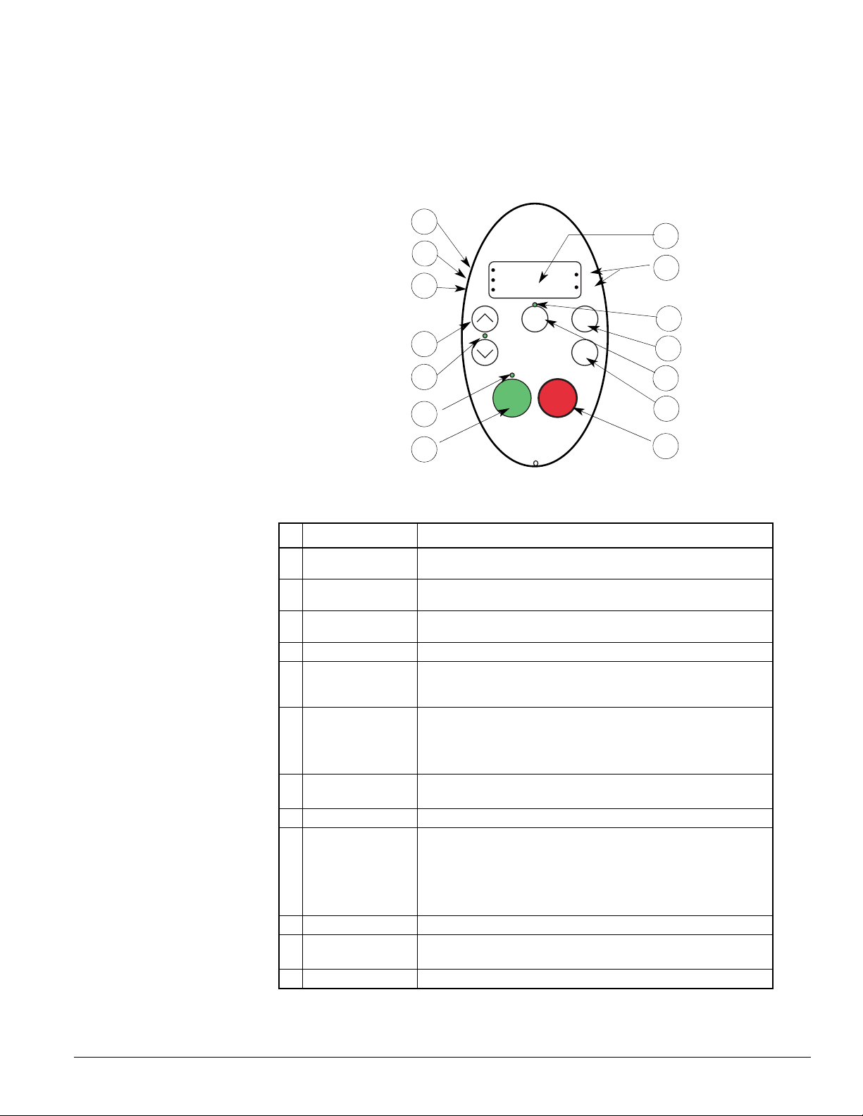
The LEDs and keys on the integrated display terminal are illustrated in Figure 4.
Figure 4: Description of Display Terminal
1
4
2
RUN
3
PRG
MON
%
Hz
5
12
13
Loc
Rem
6
7
RUN STOP
MODE
ENT
8
9
10
11
14
NOTE: Display terminal functions described above reflect VFD default settings.
Table 3: Display Terminal Features
LED/Key Characteristics
1 Display RUN LED
2 Display PRG LED
3 Display MON LED
4 Display unit Four digits, seven segments
5 Display unit LED
6 Navigation arrows
7 Arrow LED
8 Loc/Rem LED Illuminates when Local mode is selected
9Mode
10 Loc/Rem key Switches between Local and Remote modes
11 ENT
12 RUN LED Illuminates when the Run key is enabled
• Illuminates when a run command is applied to the drive controller
• Flashes when there is a speed reference present
• Illuminates when Adjustment mode is active
• Flashes in AUF–Gr.U modes
• Illuminates when Monitoring mode is active
• Flashes in fault record display mode
• The % LED illuminates when a displayed numeric value is a
percentage
• The Hz LED illuminates when a displayed numeric value is in hertz
Depending on the mode, you can use the arrows to:
• Navigate between the menus
• Change a value
• Change the speed reference when the Arrow LED (7) is lit
Illuminates when the navigation arrows are controlling the
speed reference
Press to select the Mode (see Figure 5)
• Display mode (default)
• Adjustment mode
• Monitoring mode
Can also be used to go back to the previous menu
Press to display a parameter’s value or to save a changed
value
McQuay OM 844-1 13
Page 14
Integrated Display Terminal
Table 3: Display Terminal Features (continued)
LED/Key Characteristics
13 RUN
14 STOP
Pressing this key when the RUN LED is illuminated starts the
drive controller
Stop/reset key
In Local mode (see table item #10), pressing the STOP key
decelerates the drive to a stop
In Remote mode (see table item #10), while the VFD is being
controlled by the unit controller, pressing the STOP key will
allow the drive to freewheel stop (drive display will indicate a
flashing “E”)
If F735 is set to 0 (default setting), pressing the stop key
twice will reset the flashing “E” fault and other resettable faults
if the fault condition has been resolved
DANGER
STOP BUTTON CAN CAUSE MOTOR RESTART
• The Stop Button on this drive controller can reset faults and
restart the motor if an active run command is present.
• Disable all run commands and inspect the drive system for the
cause of the fault before activating a fault reset.
• Disable the panel reset operation (F735) to remove this
hazard.
Failure to follow these instructions will result in death or
serious injury.
14 McQuay OM 844-1
Page 15
Programming
Programming
Mode Access
MD2 drive controllers have three modes of operation described in Table 4.
Table 4: Mode Descriptions
Display mode
(default)
Adjustment mode
Monitoring mode
• Active when power is applied to the drive controller
• Use to display drive controller parameters, alarms, and faults
• Use to modify drive controller parameters
• Use to monitor drive controller status
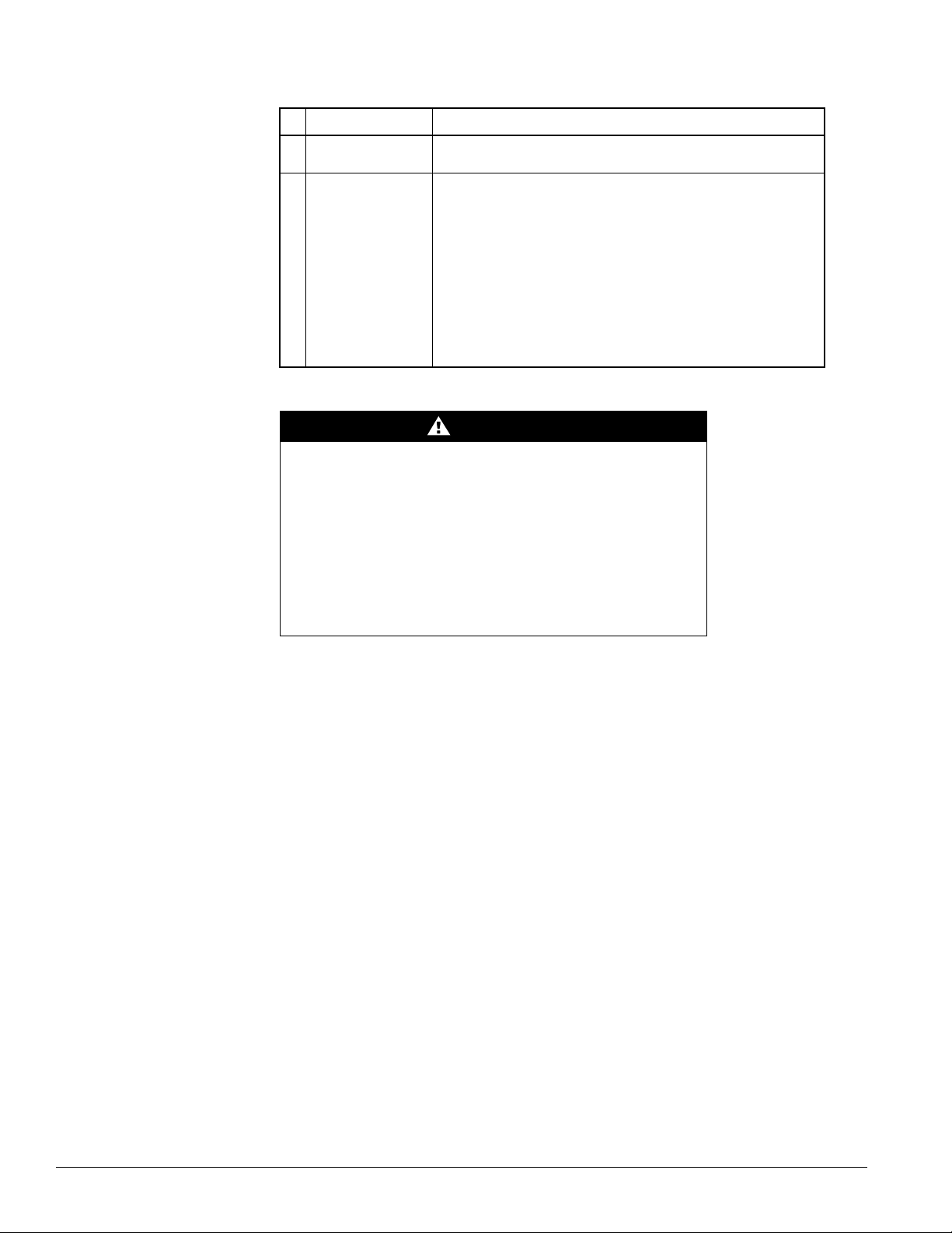
Figure 5 illustrates how to access the modes with the display terminal MODE key.
Figure 5: Mode Access
RUN
Display mode
(default)
60.0
MODE
PROG
Adjustment
mode
AUF
Monitoring
MODE MODE
mode
Fr-F
MON
Parameter Groups
MD2 drive controllers are factory programmed per your HVAC application (refer to
Appendix E—Wiring Diagrams and Parameter Settings for your application options
and settings).To restore McQuay factory settings, use parameter “tYp” (see Default
Setting on page 22).
WARNING
UNINTENDED EQUIPMENT OPERATION
• Any parameter values altered from the VFD control panel will
affect the operation of the drive.
• If parameter “
parameters will be transferred into the VFD memory and may
affect safe operation of the equipment.
Failure to follow this instruction can result in death, serious
injury, or equipment damage.
tYp” is selected and changed, altered
Table 5: MD2 Parameter Groups
Parameter Type Description
Basic parameters Parameters that need validation before using the drive controller.
Extended Parameters
(menu F---)
User Parameters (menu
Gr.U.)
Quick menu (menu AUF) Subset of Basic and Extended parameters frequently used.
History Parameters (menu
AUH)
McQuay OM 844-1 15
Parameters for special settings and applications.
Subset of Basic and Extended parameters whose values have
changed from the VFD default settings.
Subset of Basic and Extended parameters displaying the five
parameters that were last changed, displayed in reverse
chronological order.
Page 16
Programming
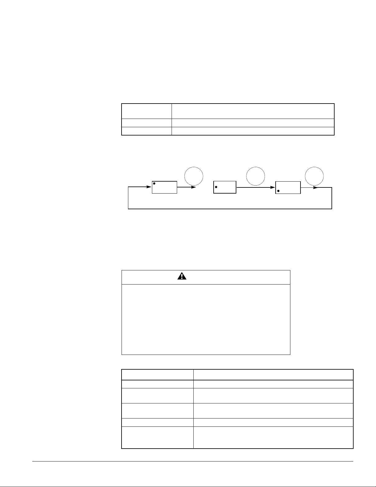
Access to Menus and Parameters
Figure 6 illustrates how to access menus.
Figure 6: Menu Access
Display
Mode
RUN
MOD
60.0
Adjustment
Mode
AUH
PROG
MOD
MOD
AUF
Monitoring
Mode
Fr-F
Figure 7: Access to Parameters
AU1
ENT
ACCAUF
GrU
F---
Basic
Parameters
AUF
AU1
10.1
NOTE: Press the MODE key to
go back to the previous level.
For example:
— To go from 9.9 to
dEC
— To go from
AUF
dEC
to
ENT
dEC
LL
10
9.9
ENT
Confirm value
16 McQuay OM 844-1
Page 17
AUF Quick Menu
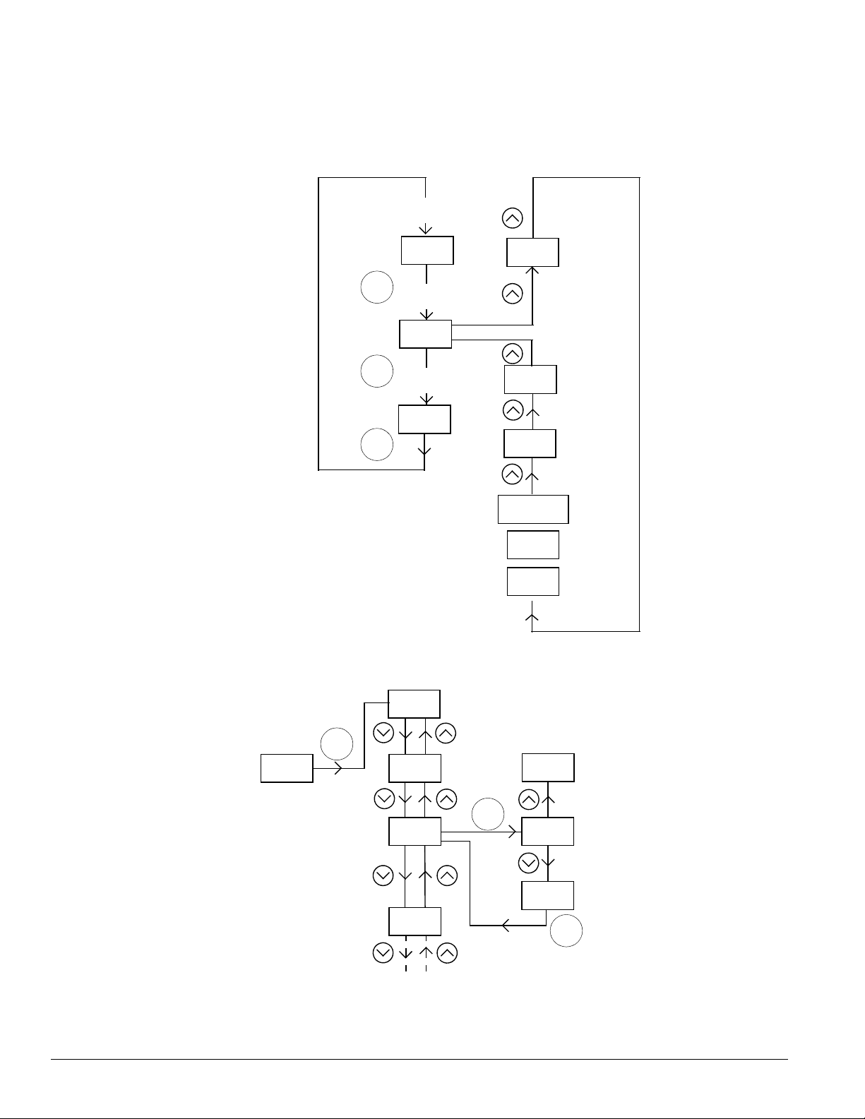
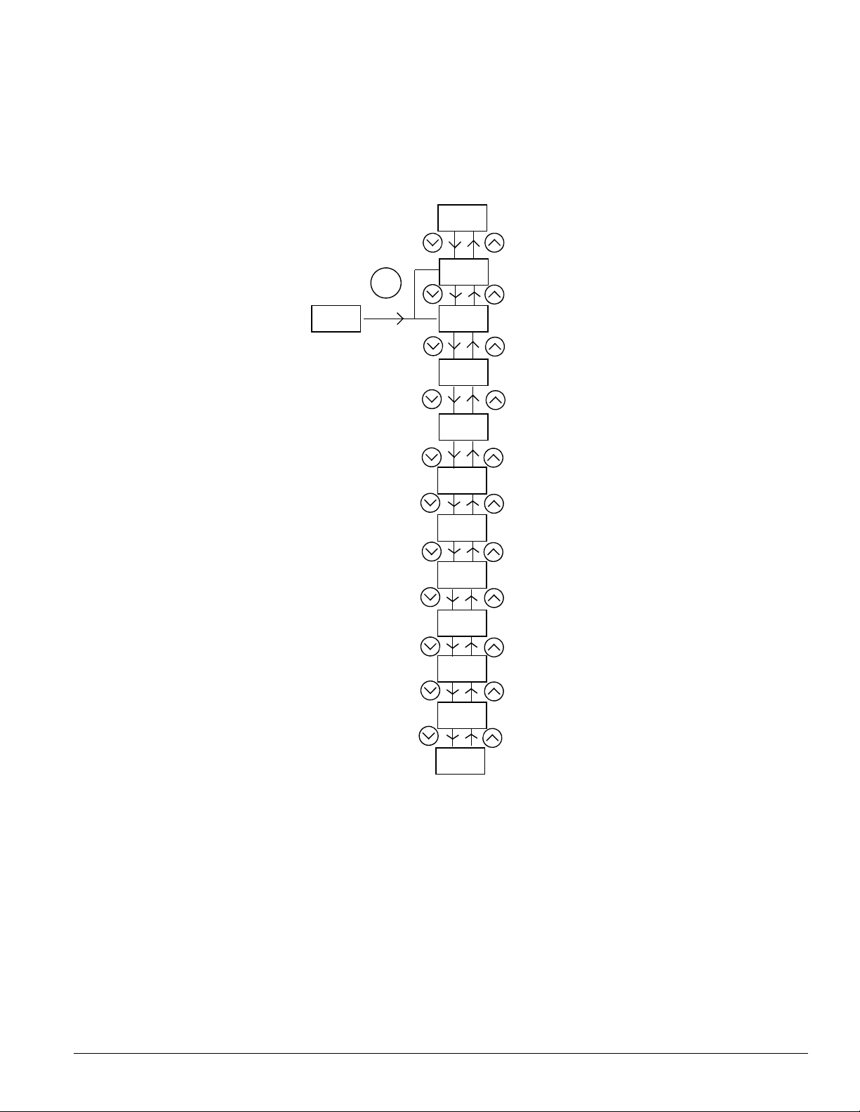
AUF Quick Menu
Figure 8 illustrates the parameters accessible from the AUF Quick menu.
Figure 8: AUF Quick Menu Parameters
ENT
HEAD
AU1
ACCAUF
dEC
LL
UL
tHr
FN
Pt
Top of list
Automatic ramp adaptation
Acceleration ramp times
Deceleration ramp times
Minimum motor frequency
Maximum motor frequency
Motor thermal protection
Analog output scaling
Motor control profile
uL
uLu
END
Nominal motor frequency
Nominal motor voltage
End of list
McQuay OM 844-1 17
Page 18

AUF Quick Menu
AUF Quick Menu Parameters
Table 6 describes the parameters that can be accessed from the AUF Quick menu.
With the exception of ACC and dEC, the parameters cannot be modified while the
drive controller is running.
Table 6: AUF Quick Menu Parameters
Code Description Unit Adjustment Range
ACC Acceleration time Seconds 0.0 to 3200
dEC Deceleration time Seconds 0.0 to 3200
LL
UL
tHr
FN Analog output scaling — Do not use
Pt
uL
uLu
1
Frequency lower limit (minimum
motor frequency)
Frequency upper limit (maximum
motor frequency)
Motor electronic thermal
protection level in amperes.
Adjust tHr to the nominal
current value which appears on
the motor nameplate.
Selection of Volts/Hz control
mode (motor control profile)
Base frequency (nominal motor
frequency)
Voltage at base frequency
(nominal motor voltage)
In is the nominal drive current shown on the drive controller nameplate.
Hz 0.0 to uL
Hz 0.5 to 200.0
A 0.1 to 1 times In
0: V/Hz profile constant torque
1: V/Hz profile variable torque
2: Automatic voltage boost
—
Hz 25 to 200.0
V
3: Flux vector control
4: Energy saving
6: Permanent magnet
synchronous motor
50 to 330 (230 V drive
controllers)
50 to 660 (460 V drive
controllers)
1
NOTE: With the exception of
drive controller is running.
18 McQuay OM 844-1
ACC
and
dEC
, the parameters cannot be modified while the
Page 19
Setting the Acceleration/Deceleration
O
f
Output
s)
Ramp Times
AUF Quick Menu
-<$
Acceleration/deceleration ramp adaptation. Automatically adjusts the
acceleration/deceleration ramp times to match the inertia of the load.
-//
Programs the time it takes for the drive controller output frequency to go from
0 Hz to the maximum frequency (parameter FH).
@1/
Programs the time it takes for drive controller output frequency to go from
maximum frequency (parameter FH), to 0 Hz.
Table 7: Setting Ramp Time Parameters
Parameter Name Range
AU1
Automatic
Acceleration/
Deceleration Ramp
Adaptation
0: Disabled
1: Automatic
2: Automatic acceleration only
(Do not use)
ACC Acceleration Time 1 0.0 to 3200 s
dEC Deceleration Time 1 0.0 to 3200 s
See Appendix E—Wiring Diagrams and Parameter Settings on page 65 for McQuay
settings.
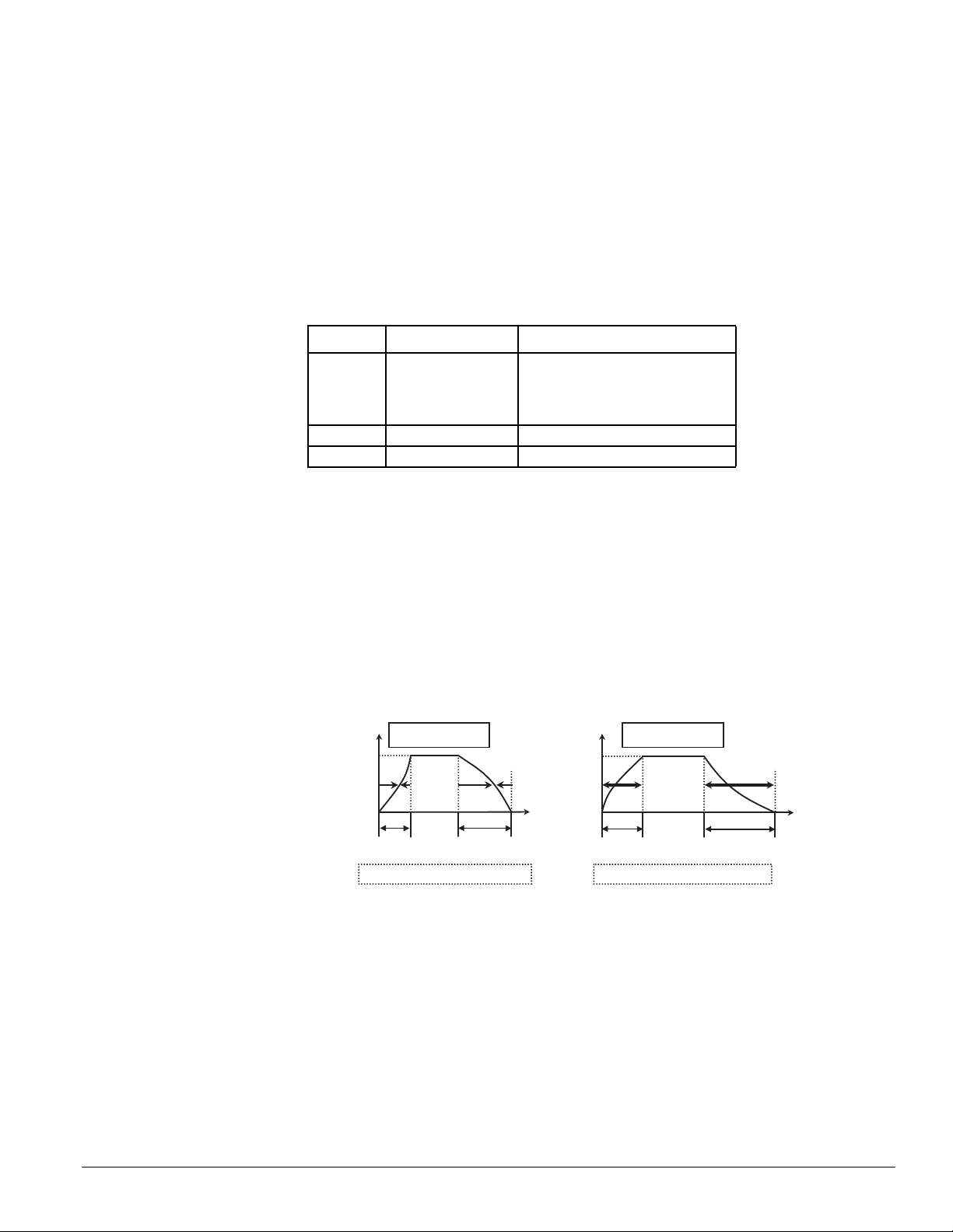
Acceleration/Deceleration Ramp Adaptation
• AU1 = 0: Function is disabled.
• AUI = 1: Automatically adjusts the acceleration and deceleration ramp times
from 1/8–8 times the value set in the ACC or dEC parameters, depending on the
current rating of the drive controller.
• AUI = 2: Do not use.
Figure 9: Automatic Ramp Adaptation
utput
requency (Hz)
When load is small ... When load is large ...
FH
0
Acceleration
Time
shorten acceleration/deceleration time. lengthen acceleration/deceleration time.
Deceleration
Time
frequency (Hz)
Time
(seconds)
FH
0
Acceleration
Time
Deceleration
Time
Time
(second
McQuay OM 844-1 19
Page 20
AUF Quick Menu
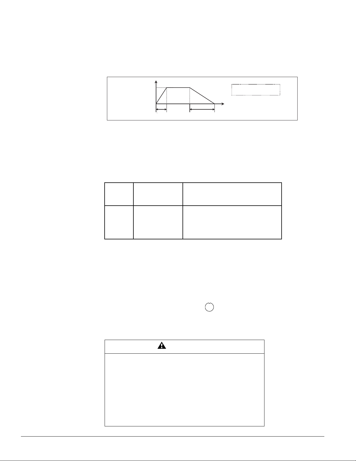
Manually Setting Acceleration/Deceleration Ramp Times
During startup, confirm parameters ACC and dEC match the parameters in
Appendix E—Wiring Diagrams and Parameter Settings.
Figure 10: Manually Setting the Acceleration/Deceleration Ramp Times
Output frequency (Hz)
FH
0
ACC dEC
AUI=0 (Manual)
Time (seconds)
Setting the Macro Function
-<'
Table 8: Parameter AU4
Parameter Name
AU4 Macro Function
NOTE: The current setting of this parameter is shown on the left side of the display. The number
0 is always displayed on the right. For example, indicates that the freewheel stop
setting is enabled.
Sets the drive controller to one of four macro configurations. The macro
configuration selection automatically determines the settings of the following
parameters: CMOd, FMOd, F110–F113, and F201.
Range (refer to Appendix E—Wiring
Diagrams and Parameter Settings for
values)
0: Disabled
1: Freewheel stop
2: 3-wire operation
3: + - speed from logic input(s)
4: 4–20 mA current input operation
$#
Setting the Mode of Operation
In Remote mode, start and stop commands and the frequency are determined by the
settings of CMOd (Command mode) and FMOd (Frequency Setting mode).
LOC
When Local mode is selected with the key, start/stop commands and frequency
settings can only be made from the display terminal. The Local LED illuminates while
Local mode is selected. See page 13 for Local/Remote key operation and Local LED.
When service is complete, return the VFD to the remote mode.
WARNING
UNINTENDED EQUIPMENT OPERATION
• Modifying or changing parameters whose function is not
described in this manual will affect drive controller operation.
Some register changes will take effect as soon as they are
entered.
• Do not modify or change parameters whose function is not
described in this instruction bulletin.
Failure to follow this instruction can result in death or serious
injury.
20 McQuay OM 844-1
REM
Page 21
Command Mode Selection
AUF Quick Menu
CNOd
Specifies which command source has priority in issuing Start and stop
commands.
NOTE: You must stop the drive controller before changing the setting of
CMOd
.
Table 9: Parameter CMOd
Parameter Name Range
0: Terminal board
1: Display terminal
2: Serial communication
CNOd
Command Mode
Selection
• CMOd = 0: Start and stop commands via the logic inputs on the control terminal
board.
• CMOd = 1: The and keys on the display terminal start and stop the drive
controller.
• CMOd = 2: The serial link sends start and stop commands to the drive controller.
Some functions, when assigned to an input terminal, are commanded by the input
terminal even if CMOd is set to 1 (display terminal).
Priority commands via a serial link can take precedence over the setting of CMOd.
Frequency Mode Selection
289@
command.
Table 10: Parameter FMOd
Specifies which input device has priority in issuing a speed reference
Parameter Name Range
1: VIA
2: VIB (not used with McQuay
FNOd
NOTE: You must stop the drive controller before changing the setting of
operation is allowed with all settings of
Frequency Mode
Selection
controls)
3: Display terminal
4: Serial communication (not used
with McQuay controls)
5: +/- speed from logic input(s)
FMOd
.
FMOd
. Preset speed
• FMOd = 1: Speed Reference command via analog input terminal VIA (0-10 Vdc
or 4-20 mAdc).
• FMOd = 2: Speed Reference command via analog input terminal VIB (0-10 Vdc)
- not used with McQuay controls.
• FMOd = 3: Speed reference via the and arrow keys on the display
terminal or the optional remote keypad.
• FMOd = 4: Speed reference via serial communication link - not used with
McQuay controls.
• FMOd = 5: Speed reference from +/- speed from logic input(s)
McQuay OM 844-1 21
Page 22

AUF Quick Menu
Default Setting
tYp
This parameter provides a variety of functions to reset, restore and save
parameter settings.
WARNING
UNINTENDED EQUIPMENT OPERATION
• Drive controller default parameter settings will be substituted for
the present settings when value 3 (standard default settings) of
thetYP parameter is selected.
• Drive controller default parameter settings may not be compatible
with the application.
• Contact McQuay product support before initiating standard
default settings.
Failure to follow these instructions can result in death, serious
injury, or equipment damage
Table 11: Parameter tYP
Parameter Name Range
0:
1: 50 Hz default
2: 60 Hz default
3: Standard default settings (Initialization)
tYp Default Setting
4: Clear the fault record
5: Clear the cumulative operation time
6: Initialize the type information
7: Save the user-defined parameters (do not use)*
8: Recalls your McQuay defined parameters
9: Clear the cumulative fan operation time
* You may replace McQuay parameters if this is used.
NOTE: You must stop the drive controller before changing the setting of
NOTE: The following parameters are not affected by settings 1, 2,
and 3:
FN, FNSL, F109, F470F473
NOTE: The setting display of this parameter contains two numbers. The left-most number
displays the last operation performed. The right-most number indicates the pending operation
and should be adjusted for the action desired.
, and
F880
.
tYP
.
Forward/Reverse Run Selection
Fr
keypad display.
Table 12: Parameter 2H
Parameter Name Range
Fr
NOTE: For more information, contact your McQuay representative.
22 McQuay OM 844-1
Programs the direction of motor rotation when starting the drive from the
Forward/
Reverse Run
Selection
0: Forward run
1: Reverse run (do not use)
2: Forward run with forward/ reverse switching (do not use)
3: Reverse run with forward/reverse switching (do not use)
Page 23
Maximum Frequency
AUF Quick Menu
FH
Programs the maximum output frequency of the drive controller. This value is
used as the maximum frequency reference for the acceleration and
deceleration ramps.
CAUTION
UNINTENDED EQUIPMENT OPERATION
• Do not use above 60Hz.
Failure to follow this instruction can result in equipment
damage.
Table 13: Parameter FH
Parameter Name Range
FH
NOTE: You must stop the drive controller before changing the
setting of FH.
Figure 11: Maximum Frequency
Output frequency (Hz)
Maximum
Frequency
80 Hz
60 Hz
30–200 (Hz)
When FH = 80 Hz
When FH = 60 Hz
NOTE:
NOTE:
0
FH
can not be adjusted during operation
UL
value can not exceed FH value.
100 % Frequency setting signal (%)
McQuay OM 844-1 23
Page 24
AUF Quick Menu
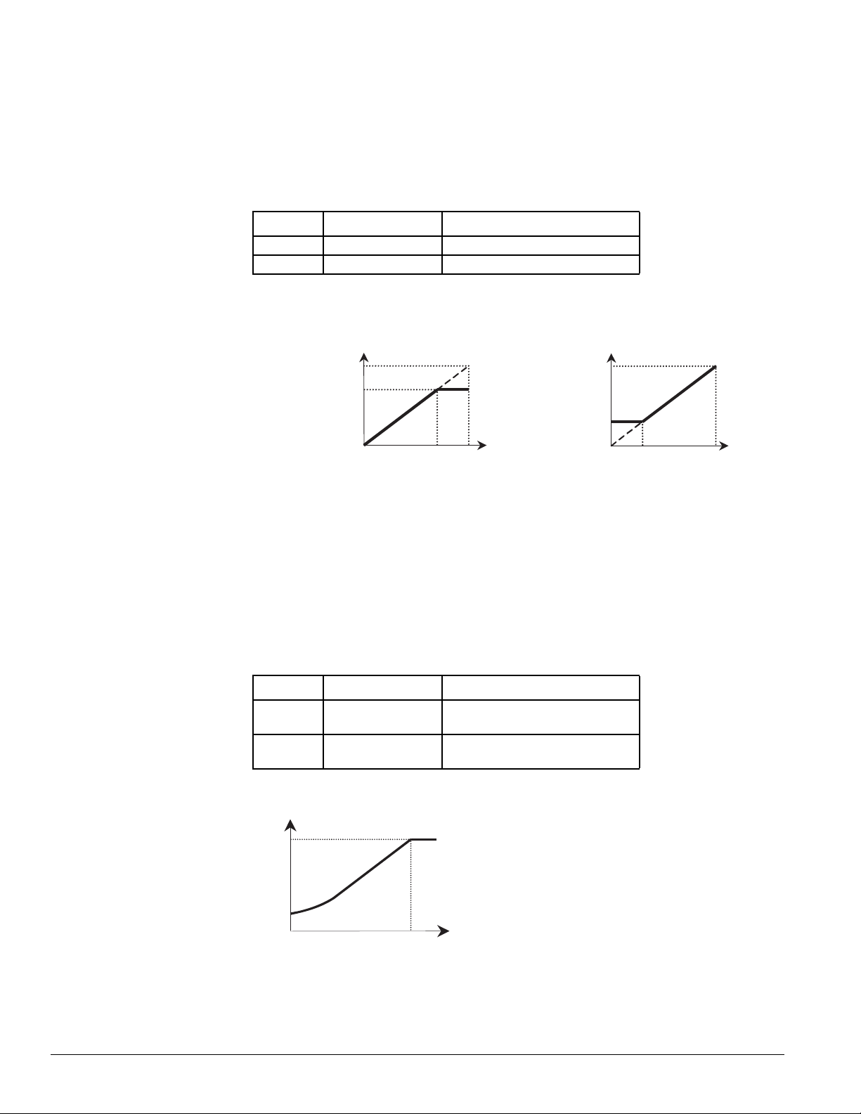
High Speed and Low Speed
UL
LL
Programs the high speed.
Programs the low speed.
Table 14: Parameters UL and LL
Parameter Name Range
UL High Speed 0.5–FH (Hz)
LL Low Speed 0.0–UL (Hz)
Figure 12: High speed and low speed
High Speed Low Speed
Output frequency (Hz) Output frequency (Hz)
uL
0 100 %
Speed Reference signal Speed Reference signal
LL
0
100 %
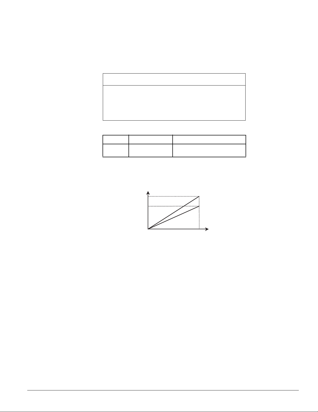
Nominal Motor Frequency and Voltage Settings
J7, J7J
Table 15: Parameters J7 and J7u
Parameter Name Range
uL
uLu Voltage Setting
Figure 13: Nominal motor frequency and voltage settings
uLu
Output voltage (V)
0
Use these parameters to set the nominal motor frequency (uL) and
voltage settings (uLu) to the motor nameplate values.
Nominal Motor
Frequency
Output frequency
25.0–200.0 Hz
50.0–330 V: 200 V Class
50.0–660 V: 400 V Class
uL
24 McQuay OM 844-1
Page 25

V/Hz Control Mode Selection
AUF Quick Menu
Pt
Use this parameter to set the V/Hz control mode.
Table 16: Parameter Pt
Parameter Name Range
0: V/Hz constant (do not use)
1: Variable torque
2: Automatic voltage boost control
3: Vector control (do not use)
4: Energy saving (do not use)
5: No assignment (do not use)
6: PM motor control (do not use)
:I
V/Hz Control Mode
Selection
Voltage Boost (Energy Recovery Application Only)
ub
Table 17: Parameter ub
Parameter Name Range
ub Voltage Boost 0.0–30.0%
Use this parameter to increases the voltage boost rate. This function is useful
for applications where the torque is not adequate at low speeds.
Figure 14: Voltage Boost
uLu
(V)/(%)
Output voltage
ub
0
Output frequency (Hz)
uL
V/Hz Control Mode (Pt) must be set to 0 (V/Hz constant) or 1 (variable torque) to
use this function.
The optimum setting for Voltage Boost depends on the drive controller capacity.
Increasing Voltage Boost too much can cause the drive controller to fault on an
overcurrent at start up.
McQuay OM 844-1 25
Page 26

AUF Quick Menu
OLN
Electronic Motor Overload Protection
tHr
Motor rated current value (FLA)
Electronic motor overload characteristics
F632
Electronic motor overload memory
These parameters must be set to match the rating and characteristics of the motor
(refer to the motor nameplate, full load amps).
Table 18: Electronic Thermal Protection Parameter Settings
Parameter Name Adjustment Range
tHr
OLN
F632
1
“In.” corresponds to the drive rated current indicated on the drive controller nameplate.
Motor Electronic
Thermal Protection
Electronic Thermal
Protection
Characteristic
Electronic Motor
Thermal State
Memory
0.1–1.0 In.1 Set to the rated current indicated on
the motor nameplate.
Setting Value
0
1 Enabled Enabled
2 Disabled Disabled
3 Disabled Enabled
4
(do not use)
5
(do not use)
6
(do not use)
7
(do not use)
Cooled
Motor
Forced
Cooled
Motor
0: Disabled
1: Enabled
Overload
Protection
Enabled Disabled
Self
Enabled Disabled
Enabled Enabled
Disabled Disabled
Disabled Enabled
Overload
Stall
CAUTION
MOTOR OVERHEATING
This drive controller does not provide direct thermal protection for
the motor. Use of a thermal sensor in the motor may be required for
protection at all speeds and load conditions. Consult the motor
manufacturer for thermal capability of the motor when operated
over the desired speed range.
Failure to follow this instruction can result in injury or
equipment damage.
26 McQuay OM 844-1
Page 27

AUF Quick Menu
Setting tHr, and OLM
Use electronic thermal protection characteristics (OLM) to enable or disable the
motor overload fault function (97%) and the overload stall function.
While the drive controller overload fault (OL1, see page 26) is always enabled,
motor overload fault (97%) can be selected using parameter OLM.
Overload stall is used with variable torque loads such as fans, pumps, and blowers, in
which the load current decreases as the operating speed decreases. When the drive
controller detects an overload, overload stall automatically lowers the output
frequency before the motor overload fault, OL2, is activated. This function maintains
the motor at frequencies that allow the load current to remain balanced so that the
drive controller can continue operation without tripping.
NOTE: Do not use overload stall with constant torque loads such as conveyor belts in which
load current is fixed with no relation to speed.
Self Cooled Motors
To set electronic thermal protection characteristics, OLM, for a self-cooled motor,
refer to Table 18.
If the capacity of the motor is smaller than the capacity of the drive controller, or the
rated current of the motor is smaller than the rated current of the drive controller, set
the electronic thermal protection level, tHr, to the motor's nominal rated current
value.
Figure 15: Motor Electronic Thermal Protection:
Self-cooled motor
Output current factor
(%)/(A)
tHr
x 1.0
tHr
x 0.55
0
Output frequency (Hz)30 Hz
Motor Electric Thermal Protection Retention, 2)&%
The setting of this parameter determines whether electric thermal calculation values
are retained when power is removed. Enabling the parameter (F632 = 1) causes
the electric thermal calculation values to be retained when power is removed.
NOTE: For installations to meet Article 430 of the National Electric Code, parameter F632 must
be set to 1.
McQuay OM 844-1 27
Page 28

AUF Quick Menu
Input Signal Selection
2$#,
VIA terminal function selection
This parameter allows you to select an analog or digital input for the VIA terminal.
Table 19: Parameter F109
Parameter Name Range
0: Analog input
1: Do not use (sinking input
assignment)
2: Digital (sourcing) input
F109
Analog/Digital Input
Function Selection
(VIA Terminal)
When using the VIA terminal as a digital input terminal, set the VIA slide switch to the
V position. For switch location see Figure 2.
DANGER
UNINTENDED EQUIPMENT OPERATION
• The accidental grounding of logic inputs configured for Sink Logic
can result in unintended activation of drive controller functions.
• Protect the signal conductors against damage that could result in
unintentional conductor grounding.
• Follow NFPA 79 and EN 60204 guidelines for proper control
circuit grounding practices.
Failure to follow these instructions will result in death or
serious injury.
Terminal Function Selection
Modifying Input Terminal Functions
Table 20: Parameters F110, F111, F112, F113, and F118
Terminal
Symbol
— F110
F F111 Logic Input
R F112 Logic Input
RES F113 Logic Input
VIA F118 Input Terminal
The functions selected with parameters F110 are always active.
Parameter Name Range
Always-Active Function (the
control input function assigned to
this parameter will always be
active).
(refer to Appendix E—
Wiring Diagrams and
0–71
Parameter Settings)
28 McQuay OM 844-1
Page 29

Modifying Output Terminal Functions
Jumping width 1 (
F271
)
Jumping width 2 (
F273
)
Jumping width 3 (
F275
)
Jump frequency 3 (
F274
)
Jump frequency 1 (
F270
)
Jump frequency 2 (
F272
)
Output command frequency
(Hz)
Frequenc y setting si gnal
0
AUF Quick Menu
2$&#
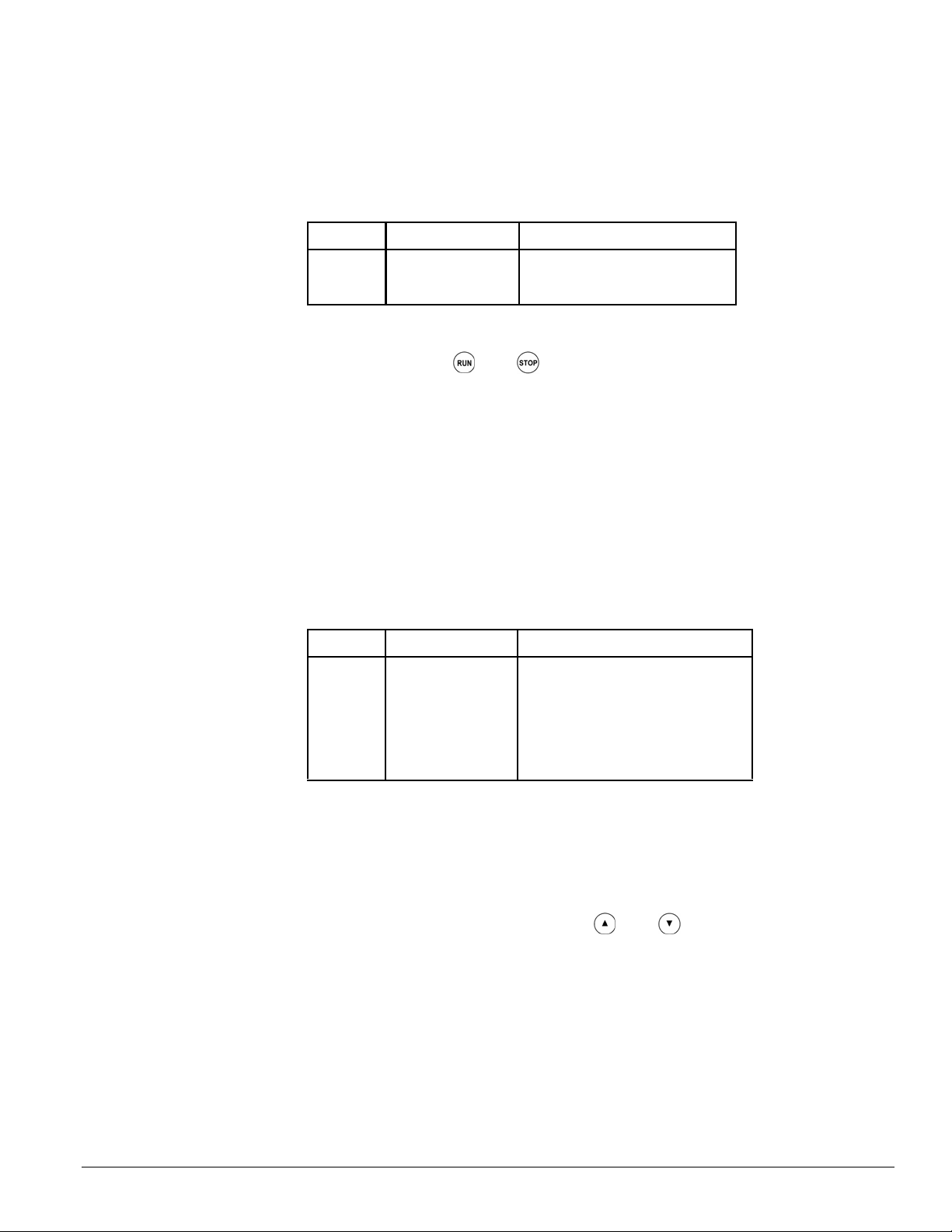
Output terminal selection 1A (RY-RC)
Figure 16: Application Example
RY
Function of RY-RC:
Can be set using parameter F130
RC
RY
Table 21: Assigning One Function to an Output Terminal
Terminal
Symbol
RY-RC F130
Parameter Name Range
0–255
(Refer to Appendix
Output Terminal
Selection 1A
E—Wiring Diagrams
and Parameter
Settings on page 65,
for McQuay settings)
Jump Frequency (Jumping Resonant Frequencies)
2%*#
2%*$
2%*%
2%*&
2%*'
2%*(
Resonance due to the natural frequency of the mechanical system can be avoided by
jumping the resonant frequency during operation.
Figure 17: Jump Frequency Timing Diagram
Jump Frequency 1
Jumping Width 1
Jump Frequency 2
Jumping Width 2
Jump Frequency 3
Jumping Width 3
McQuay OM 844-1 29
Page 30

AUF Quick Menu
Table 22: Jump Frequency Parameter Setting
Parameter Name Range
F270 Jump Frequency 1 0.0–FH (Hz)
F271 Jump Width 1 0.0–30.0 (Hz)
F272 Jump Frequency 2 0.0–FH (Hz)
F273 Jump Width 2 0.0–30.0 (Hz)
F274 Jump Frequency 3 0.0–FH (Hz)
F275 Jump Width 3 0.0–30.0 (Hz)
NOTE: The jump frequency plus jump width may not overlap another jump frequency plus jump
width.
NOTE: During acceleration or deceleration, the jumping function is disabled for the operation
frequency.
Switching Frequency
2&##
2&$%
Switching Frequency
Random Mode
The F300 parameter allows the audible noise from the motor to be changed by
altering the switching frequency.
In addition, the F300 parameter reduces the electromagnetic noise generated by
the drive controller. Decrease the switching frequency to reduce electromagnetic
noise.
NOTE: Although the electromagnetic noise level is reduced when decreasing switching
frequency, the acoustic noise of the motor is increased.
The F312 parameter (random mode) reduces motor electromagnetic and acoustic
noise by changing the pattern of the switching frequency.
Table 23: Parameters F300, F312
Parameter Name Range
F300 Switching Frequency 6.0–16.0 (kHz)
F312 Random Mode
0: Disabled
1: Enabled
30 McQuay OM 844-1
Page 31

Auto Restart
AUF Quick Menu
2&#&
Select the number of restarts
DANGER
AUTOMATIC RESTART ENABLED
• This drive controller can restart under fault conditions.
• Equipment must be shut down, locked out and tagged out to
perform servicing or maintenance.
Failure to follow these instructions will result in death or
serious injury.
This parameter resets the drive controller automatically if it is in an alarm state.
Table 24: Parameter F303
Parameter Name Range
F303 Number of Restarts
Table 25: Causes of Tripping and Corresponding Restart Processes
Cause of
Tripping
Momentary
power failure
Overcurrent
Overvoltage
Overload
Overheating
Restart Process Canceling Conditions
Up to 10 restarts in
succession
1st restart: 1 second
after tripping
2nd restart: 2 seconds
after tripping
3rd restart: 3 seconds
after tripping
10th restart: About 10
seconds after tripping
0: Disabled
1–10: 1 to 10 restarts
Auto restart is possible
only after the following
faults: momentary
power failure,
overcurrent,
overvoltage, or
overload.
The restart function will
be canceled if restarting
is not successful within
the specified number of
times.
Restart is disabled when the faults or errors listed in Table 26 occur.
Table 26: Faults Which Cannot Be Automatically Reset
OCA Motor overcurrent at start up
OCL Overcurrent on load side at start up
EPHO Output phase loss
OH2 External thermal fault
Ot Overtorque fault
E External fault stop
UC Low-current operation fault
UPI Undervoltage fault (main circuit)
EF2 Ground fault
EPH1 Input phase loss
EtYP Drive controller error
Err2 Main unit RAM fault
Err3 Main unit ROM fault
Err4 CPU fault
McQuay OM 844-1 31
Page 32

AUF Quick Menu
Table 26: Faults Which Cannot Be Automatically Reset
OCA Motor overcurrent at start up
OCL Overcurrent on load side at start up
EPHO Output phase loss
OH2 External thermal fault
Ot Overtorque fault
E External fault stop
UC Low-current operation fault
UPI Undervoltage fault (main circuit)
EF2 Ground fault
EPH1 Input phase loss
EtYP Drive controller error
Err2 Main unit RAM fault
Err5 Remote control error
Err7 Current detector fault
Err8 Control circuit board format error
EEP1 EEPROM fault 1
EEP2 EEPROM fault 2
EEP3 EEPROM fault 3
Etn1 Auto-tuning error
E-18 VIA input detection error
E-19 Main unit CPU communication error
E-20 Excessive voltage boost
E-21 CPU fault 2
CAUTION
MOTOR OVERHEATING
• Repeated reset of the thermal overload can result in thermal
stress to the motor.
• When faults occur, promptly inspect the motor and driven
equipment for problems such as locked shaft and mechanical
overload before restarting. Also check the power supplied to the
motor for abnormal conditions such as phase loss and phase
imbalance.
Failure to follow these instructions can result in equipment
damage.
When using Auto Restart, observe the following:
• By default, protective operation detection relay signals (FLA-FLB-FLC terminal
signals) are not sent during an auto restart process. To allow a signal to be sent to
the protective operation detection relay (FLA-FLB-FLC terminals) during an auto
restart process, assign value 36 or 37 to parameter F132.
• A calculated cooling time is provided for overload tripping (OL1, OL2, OLr). In
this case, the auto restart function operates after the calculated cooling time and
the restart time.
• In the event of an overvoltage fault (OP1–OP3), the auto restart function is not
activated until the voltage in the DC section comes down to a normal level.
• In the event of an overheating fault (OH), the auto restart function is not activated
until the drive controller temperature is low enough to restart operation.
32 McQuay OM 844-1
Page 33

AUF Quick Menu
• When F602 is set to 1 (fault retained), the restart function is not performed,
regardless of the setting of F303.
• During an auto restart process, the display alternates between “rtry” and the
setting specified by display mode selection parameter F710.
• The number of auto restarts is cleared if the drive controller does not fault for the
specified period of time after a successful restart. A successful restart means that
the drive controller output frequency reaches the command frequency without
causing the drive controller to fault again.
Drive Controller Fault Retention
2)#%
Drive controller fault retention
This parameter can be set to retain fault information for display after power has been
cycled.
Table 27: Parameter F602
Parameter Name Range
0: Clear the fault information when power
F602
Drive Controller Fault
Retention Selection
is removed
1: Retain the fault information when the
power is removed
The causes of up to four trips can be displayed in status monitor mode.
Output Phase Loss Detection
2)#(
The setting of this parameter determines how the drive controller responds after
detecting an output phase loss. If the phase loss status persists for one second or
more, the drive controller will fault, the FL relay will be activated, and fault code
EPHO will be displayed.
Output phase loss detection mode
Table 28: Parameter F605
Parameter Name Range
0: Disabled
1: At start-up (only one time after power is
Output Phase Loss
F605
NOTE: If the drive controller detects an all-phase loss (i.e. contactor opening), it will restart on
completion of recondition. The drive controller does not check for output phase loss when
restarting after a momentary power loss.
McQuay OM 844-1 33
Detection (one
second or greater).
turned on)
2: At start-up (each time)
3: During operation
4: At start-up and during operation
5: Detection of cutoff on output side
Page 34

AUF Quick Menu
DC Voltage
Output
Frequency
F626
:
Over-voltage stall protection level
Input Phase Loss Detection
2)#+
Input phase loss detection mode selection
Setting this parameter to 1 (default) enables Input Phase Loss Detection. During a
complete input phase loss event the drive controller will fault (code EPHI) and the
FL relay will be activated.
NOTE: The drive controller may not fault on all input phase imbalance conditions.
Input phase loss nuisance tripping on low source impedance power systems may
indicate the need to install an AC input line reactor.
Table 29: Parameter F608
Parameter Name Range
F608 Input Phase Loss Detection
0: Disabled
1: Enabled
Setting F608 to 0 (input phase loss detection disabled) may result in damage to the
drive controller if operation is continued under a heavy load during an input phase
loss.
Avoiding Overvoltage Tripping
2&#(
2)%)
Overvoltage limit operation
Overvoltage stall protection level
Use these parameters to keep the output frequency constant, or to increase it to
prevent overvoltage tripping should the voltage in the DC section rise during
deceleration or varying speed operation. The deceleration time during overvoltage
limit operation may increase above the designated time. Overvoltage stall protection
level sets the percentage of the nominal DC bus level where the drive will modify the
output frequency to prevent an Overvoltage fault.
Figure 18: Overvoltage Limit Operation Level
CAUTION
MOTOR OVERHEATING
• Repetitive braking can cause motor overheating and damage if
the Quick Deceleration or Dynamic Quick Deceleration features
are active.
• Use of a thermal sensor in the motor is recommended to protect
the motor during repetitive braking.
Failure to follow these instructions can result in injury or
equipment damage.
34 McQuay OM 844-1
Page 35

AUF Quick Menu
Table 30: Parameters F305, F626
Parameter Name Range
0: Enabled
F305
F626
* McQuay setting = 140%. If power transients are more common than normal, increase toward
150%.
Overvoltage Limit
Operation
Overvoltage Stall
Protection Level
1: Disabled
2: Enabled (quick deceleration - do not use)
3: Enabled (dynamic quick deceleration - do
not use)
100–150%*
If F305 is set to 2 (quick deceleration), the drive controller will increase the voltage
to the motor (over-excitation control) to increase the amount of energy consumed by
the motor when the voltage reaches the overvoltage protection level. The motor can
therefore be decelerated more quickly than with normal deceleration.
If F305 is set to 3 (dynamic quick deceleration), the drive controller will increase the
voltage to the motor (over-excitation control) to increase the amount of energy
consumed by the motor as soon as the motor begins to slow down. The motor can
therefore be decelerated even more quickly than with quick deceleration.
Undervoltage Fault
2)%*
The setting of this parameter determines how the drive controller responds when it
detects an undervoltage. The fault code displayed is UPI.
Table 31: Parameter F627
Parameter Name Range
F627
Undervoltage fault/alarm selection
0: Alarm only (input voltage level below 60%)
The drive controller stops but does not fault
(the FL relay is not activated).
1: Fault (detection level below 60%)
The drive controller stops and faults when
Undervoltage
Fault/Alarm
Selection
the input voltage is less than 60% of it's
rating.
2: Alarm only (input voltage level below 50%,
input reactor needed)
The drive controller stops but does not fault
when the input voltage is less than 50% of it's
rating. A line reactor must be used with this
setting.
McQuay OM 844-1 35
Page 36

AUF Quick Menu
Changing the Display Parameter
2*$#
Display selection
When power is applied to the drive controller, it is in display mode. The display
terminal shows operation frequency as the default setting.
Table 32: Parameter F710
Parameter Name Range
0: Operation frequency (Hz/free unit/step)
1: Frequency command (Hz/free unit/step)
2: Output current (%/A)
3: Drive controller rated current (A)
4: Drive controller load factor (%)
5: Output power
6: Frequency command after PID control (Hz/free
unit/step)
7: Optional item specified from an external control
unit
8: Output speed of fan motor
9: Communication counter
10: Normal state communication counter
F710
Display
Selection
36 McQuay OM 844-1
Page 37

Troubleshooting Fault and Alarm Codes
Troubleshooting Fault and Alarm Codes
When an alarm or fault occurs, use Tables 33 and 34 to diagnose and resolve the
problem.
If the problem cannot be resolved by any of the actions described in the tables, refer
to the programming guide or contact your McQuay representative.
Drive Controller Fault Conditions
Table 33: Fault Codes
Error
Code
OC1
OC1p
OC2
OC2P
OC3
OC3P
0C1p
0C2p
0C3p
Failure
Code
0001
0025
0002
0026
0003
0027
0025
0026
0027
Problem Possible Causes Remedies
• Increase the acceleration
time, ACC.
Overcurrent
during
acceleration
Transistor
overcurrent
Overcurrent
during
deceleration
Transistor
overcurrent
Overcurrent
during constant
speed operation
Transistor
overcurrent
Ground fault
Motor
overcurrent at
start-up
(for 15 and 20
hp models only)
• The acceleration time
ACC is too short.
• The V/Hz setting is
improper.
• A restart signal is input to
the rotating motor after a
momentary stop, etc.
• A special motor (e.g.
motor with a small
impedance) is used.
• Possible ground fault.
• The deceleration time
dECis too short.
• Possible ground fault.
• The load fluctuates
abruptly.
• Mechanical blockage
• A current leaked from an
output cable or the motor
to ground.
• A main circuit elements
is defective.
• Check the V/Hz
parameter.
• Use F301 (auto-
restart) and F302(ride-
through control).
• Adjust the switching
frequency F300.
• Set the switching
frequency control mode
selection parameter
F316 to 1 or 3
(switching frequency
decreased automatically).
• Increase the deceleration
time dEC.
• Set the switching
frequency control mode
selection parameter
F316 to 1 or 3
(switching frequency
decreased automatically).
• Reduce the load
fluctuation.
• Check the load (operated
machine).
• Set the switching
frequency control mode
selection parameter
F316 to 1 or 3
(switching frequency
decreased automatically).
• Contact your Mcquay
representative.
• Check the cables
connecting the drive
controller to the motor,
and check the motor
insulation.
• Reduce the switching
frequency.
• Connect output filters in
series with the motor.
McQuay OM 844-1 37
Page 38

Troubleshooting Fault and Alarm Codes
Table 33: Fault Codes (continued)
Error
Code
Failure
Code
Problem Possible Causes Remedies
Overcurrent (an
OCL 0004
overcurrent on
the load side at
start-up)
Motor
OCA 0005
overcurrent at
start-up
EpH1* 0008 Input phase loss
EPH0* 0009
Output phase
loss
Overvoltage
Op1 000A
during
acceleration
Overvoltage
Op2 000B
during
deceleration
• The insulation of the
output main circuit or
motor is defective.
• Motor impedance is too
low
• Current is leaked from an
output cable or the motor
to ground.
• A main circuit elements
is defective.
• Possible ground fault
• Input phase loss, blown
fuse
• Three-phase drive
controller used on a
single phase line supply
• Input phase imbalance
• Transient phase fault
• Loss of phase at drive
controller output
• Downstream contactor
open
• Motor not connected
• Instability in the motor
current
• Drive controller
oversized for motor
• Line voltage too high
• Line supply transients
• A restart signal is input to
the rotating motor after a
momentary stop, etc.
• There is possibility of
output phase loss.
• The deceleration time
dEC is too short.
(regenerative energy is
too large.)
• F305 (overvoltage
limit operation) is off.
• The input voltage
fluctuates abnormally:
• Overhauling load
• There is possibility of
output phase loss.
• Check the cables and
wires for defective
insulation.
• Check cables,
connectors, and so on for
ground faults.
• Check the cables
connecting the drive
controller to the motor,
and check the motor
insulation.
• Reduce the switching
frequency.
• Connect output filters in
series with the motor.
• Contact your McQuay
representative.
• Check the main circuit
input line for phase loss.
• Enable F608 (input
phase loss detection).
• Check the main circuit
output line, motor, etc. for
phase loss.
• Enable F605 (output
phase loss detection).
• Check the line voltage.
Compare with the drive
controller nameplate
rating.
• Reset the drive controller.
• Install a line reactor
• Use F301 (auto-
restart) and F302 (ridethrough control).
• Check the main circuit
output line, motor, etc. for
phase loss.
• Increase the deceleration
time dEC.
• Enable F305
(overvoltage limit
operation).
• Check the main circuit
output line, motor, etc. for
phase loss.
38 McQuay OM 844-1
Page 39

Table 33: Fault Codes (continued)
Troubleshooting Fault and Alarm Codes
Error
Code
Failure
Code
Problem Possible Causes Remedies
Overvoltage
Op3 000C
during constantspeed operation
OL1 000D
Drive controller
overload
OL2 000E Motor overload
Ot*
0020
Over-torque
fault
OH
Drive controller
0010
over
temperature
OH2
002E
External thermal
fault
E 0011 Emergency stop
• The input voltage
fluctuates abnormally.
• The motor is in a
regenerative state
because the load causes
the motor to run at a
frequency higher than
the drive controller
output frequency.
• There is possibility of
output phase loss.
• The acceleration time
ACC is too short.
• The DC braking level is
too large.
• The V/Hz setting is
improper.
• A restart signal is input to
the rotating motor after a
momentary stop, etc.
• The load is too large.
• The V/Hz setting is
improper.
• The motor is locked.
• Low-speed operation is
performed continuously.
• An excessive load is
applied to the motor
during operation.
• Over-torque during
operation.
• The cooling fan does not
rotate.
• The ambient
temperature is too high.
• The vent is blocked.
• A heat generating device
is installed close to the
drive controller.
• The thermistor in the unit
is broken.
• External thermal fault.
• External PTC probe
fault.
• During automatic
operation or remote
operation, a stop
command is entered
from the operation panel
or a remote input device.
• Check the main circuit
output line, motor, etc. for
phase loss.
• Increase the acceleration
time ACC.
• Reduce the DC braking
amount F251 and the
DC braking timeF252.
• Check the V/Hz
parameter setting.
• Use F301 (auto-
restart) and F302 (ridethrough control).
• Use an drive controller
with a larger rating.
• Check the V/Hz
parameter setting.
• Check the load (operated
machine).
• Adjust OLN to the
overload that the motor
can withstand during
operation in a low speed
range.
• Enable F615 (over-
torque fault selection).
• Check system error.
• Restart the operation by
resetting the drive
controller after it has
cooled down.
• The fan requires
replacement if it does not
rotate during operation.
• Ensure sufficient space
around the drive
controller.
• Do not place any heat
generating device near
the drive controller.
• Contact your McQuay
representative.
• Check the external
thermal input.
• Check the PTC in the
motor.
• Reset the drive controller.
McQuay OM 844-1 39
Page 40

Troubleshooting Fault and Alarm Codes
Table 33: Fault Codes (continued)
Error
Code
Failure
Code
Problem Possible Causes Remedies
EEp1 0012 EEPROM fault 1
EEp2 0013 EEPROM fault 2
EEp3 0014 EEPROM fault 3
Err2 0015
Err3 0016
Main unit RAM
fault
Main unit ROM
fault
Err4 0017 CPU fault 1
Err5*
0018
Err7 001A
Communication
error
Current detector
fault
Err8 001B Network error
UC* 001D
Low-current
operation fault
Undervoltage
Up1* 001E
fault
(main circuit)
EF2 0022 Ground fault
Etn* 0054
EtYp 0029
Auto-tuning
error
Drive controller
type error
• Turn off the drive
controller, then turn it
• Data writing error.
• Power supply is cut off
during tYp operation
and data writing is
aborted.
• A data reading error
occurred.
• The control RAM is
defective.
• The control ROM is
defective.
• The control CPU is
defective.
• An error arises during
serial communication.
• The current detector is
defective.
• The error has occurred
during Network
communication.
• The output current
decreased to a lowcurrent detection level
during operation.
• The input voltage (in the
main circuit) is too low.
• A ground fault occurs in
the output cable or the
motor.
• Check the motor parameter F401 to F494.
• The motor with the capacity of 2 classes or less than
the drive controller is used.
• The output cable is improperly sized.
• The motor is rotating.
• The drive controller is used for loads other than those of
three-phase induction motors.
• Circuit board is changed.
(or main circuit/drive
circuit board)
again. If it does not
recover from the error,
contact your McQuay
representative.
• Turn the power off
temporarily and turn it
back on, and then try
tYp operation again.
• Turn off the drive
controller, then turn it
again. If it does not
recover from the error,
contact your McQuay
representative.
• Contact your McQuay
representative.
• Contact your McQuay
representative.
• Contact your McQuay
representative.
• Check the remote control
device, cables, etc.
• Contact your McQuay
representative.
• Check the Network
device and wiring.
• Enable F610 (low-
current detection).
• Check the suitable
detection level for the
system (F611,
F612).
• Check the input voltage.
• Enable F627
(undervoltage fault
selection).
• To cope with a
momentary stop due to
undervoltage, enable
F302 (ride-through
control) and F301
(auto-restart).
• Check the cable and the
motor for ground faults.
• Contact your McQuay
representative.
40 McQuay OM 844-1
Page 41

Table 33: Fault Codes (continued)
Troubleshooting Fault and Alarm Codes
Error
Code
E-18* 0032
E-19 0033
E-20 0034
E-21 0035 CPU fault 2
SOUt 002F
Failure
Code
Problem Possible Causes Remedies
Break in analog
signal cable
CPU
communication
error
Excessive
voltage boost
Step-out (for PM
motor only)
• The signal input via VIA
is below the analog
signal detection level set
with F633.
• A communications error
occurs between control
CPUs.
• The voltage boost
parameter F402 is set
too high.
• Impedance of the motor
is too low
• The control CPU is
defective.
• The motor shaft is
locked.
• One output phase is
open.
• An impact load is
applied.
* You can select a trip ON/OFF by parameters.
• Check the cables for
breaks. And check the
setting of input signal or
setting value of F633.
• Contact your McQuay
representative.
• Decrease the setting of
the voltage boost
parameter F402.
• Contact your McQuay
representative.
• Unlock the motor shaft.
• Check the interconnect
cables between the drive
controller and the motor.
McQuay OM 844-1 41
Page 42

Troubleshooting Fault and Alarm Codes
Drive Controller Alarm Conditions
Alarms do not cause the drive controller to fault.
Table 34: Alarm Codes
Error
Code
OFF
Problem Possible Causes Remedies
ST terminal
OFF
Undervoltage
NOFF
in main
circuit
rtrY
Restart in
process
Frequency
Err1
point setting
error alarm
Clear
CLr
command
acceptable
Emergency
EOFF
stop
command
acceptable
Setting error
alarm /
H1
LO
An error code
and data are
displayed
alternately
twice each.
HEAd
End
Display of
first/last data
items
db DC braking
Flowing out
EI
of excess
number of
digits
Momentary
power failure
slowdown
StOp
stop
prohibition
function
activated.
Auto-stop
because of
continuous
LStp
operation at
the lowerlimit
frequency
• The ST-CC circuit is opened. • Close the ST-CC circuit.
• Measure the main circuit supply
• The supply voltage between R,
S and T is under voltage.
• The drive controller is in the
process of restart.
• A momentary stop occurred.
• The frequency setting signals
at points 1 and 2 are set too
close to each other.
• This message is displayed
when pressing the STOP key
while an error code is
displayed.
• The operation panel is used to
stop the operation in automatic
control or remote control mode.
• An error is found in a setting
when data is reading or writing.
• The first and last data item in
the auh data group is displayed.
• DC braking in process
• The number of digits such as
frequencies is more than 4.
(The upper digits have a
priority.)
• The slowdown stop prohibition
function set with F302
(momentary power failure ridethrough operation) is activated.
• The automatic stop function
selected with F256 was
activated.
voltage.
If the voltage is at a normal level,
the drive controller requires
repairing.
• The drive controller is operating
normally if it restarts after
several tens of seconds.
• Set the frequency setting signals
at points 1 and 2 apart from
each other.
• Press the STOP key again to
clear the fault.
• Press the STOP key for an
emergency stop.
To cancel the emergency stop,
press any other key.
• Check whether the setting is
made correctly.
• Press MODE key to exit the data
group.
• The message goes off in several
tens of seconds if no problem
occurs.
• Lower the frequency free unit
magnification F702.
• To restart operation, reset the
drive controller or input an
operation signal again.
• To deactivate the automatic stop
function, increase the frequency
command above the lower-limit
frequency (LL) + 0.2 Hz or turn
off the operation command.
42 McQuay OM 844-1
Page 43

Table 34: Alarm Codes (continued)
Troubleshooting Fault and Alarm Codes
Error
Code
Problem Possible Causes Remedies
Parameters
InIt
in the
process of
initialization
Operation
E-17
panel key
fault
Atn1 Auto-tuning
h999
H999
Integral input
power
Integral
output power
• Parameters are being
initialized to default values.
• The RUN or STOP key is held
down for more than 20
seconds.
• The RUN or STOP key is
faulty.
• Auto-tuning in process
• Integral input power is more
than 999.99 kWh.
• Integral output power is more
than 999.99 kWh.
• Normal if the message
disappears after a while (several
seconds to several tens of
seconds).
• Check the operation panel.
• Normal if it the message
disappears after a few seconds.
• Press and hold down the key for
3 seconds or more when power
is off or when the input terminal
function CKWH is turned on or
displayed.
• Press and hold down the key for
3 seconds or more when power
is off or when the input terminal
function CKWH is turned on or
displayed.
McQuay OM 844-1 43
Page 44

Troubleshooting Fault and Alarm Codes
Pre-Alarm Displays
Table 35: Pre-alarm codes
C
P
L Overload alarm
H
Overcurrent
alarm
Overvoltage
alarm
Overheating
alarm
Same as OC (overcurrent)
Same as OP (overvoltage)
Same as OL1 and OL2
(overload)
Same as OH (overheating)
The pre-alarms are displayed, blinking, in the following order from left to right: C, P,
L, 4.
If two or more problems arise simultaneously, one of the following alarms appears and
blinks: CP, PL, CPL.
Resetting the Drive Controller After a Fault Condition
Do not reset the drive controller when faulted because of a failure or error before
eliminating the cause of the fault. Resetting the tripped drive controller before
eliminating the problem causes it to fault again.
The drive controller can be reset after a fault with any of the following operations:
1. Turning off the power.
2. Using external signal.
3. Using the Stop key on the display terminal:
a. Press the STOP key and make sure that CLr is displayed.
b. Eliminate the cause of the fault.
c. Press the STOP key again to reset the drive controller.
4. Inputting a fault clear signal from a remote communication device.
When any overload function (OL1 or OL2) is active, the drive controller cannot be
reset by inputting a reset signal from an external device or with the Stop key on the
display terminal if the calculated cooling time has not expired. Calculated cooling time:
• OL1: 30 seconds after the fault has occurred
• OL2: 120 seconds after the fault has occurred
CAUTION
MOTOR OVERHEATING
• Repeated reset of the thermal state after a thermal overload can
result in thermal stress to the motor.
• When faults occur, promptly inspect motor and driven equipment
for problems (locked shaft, mechanical overload, etc.) before
restarting. Also check power supplied to the motor for abnormal
conditions (phase loss, phase imbalance, etc.).
Failure to follow these instructions can result in equipment
damage.
44 McQuay OM 844-1
Page 45

Appendix A—Input Terminal Functions
Appendix A—Input Terminal Functions
The input terminals F, R, and RES can be configured with the settings in Table 36.
Table 36: Input Terminal Functions
Function
No.
# - No function is assigned Disabled
$* ST Standby terminal
% F Forward run command
& R Reverse run command
( AD2
) SS1 Preset-speed command 1
* SS2 Preset-speed command 2
+ SS3 Preset-speed command 3
$#* RES Reset command
$$* EXT
$& DB DC braking command ON: DC braking
$' PID PID control prohibited
$( PWENE
$)*ST+RES
%# F+AD2
%$ R+AD2
%% F+SS1
%& R+SS1
%' F+SS2
%( R+SS2
%) F+SS3
Code Function Action
ON: Ready for operation
OFF: Coast stop (gate off)
ON: Forward run OFF: Slowdown
stop
ON: Reverse run OFF: Slowdown
stop
Acceleration/deceleration 2
pattern selection
Fault stop command from
external input device
Permission of parameter
editing
Combination of standby
and reset commands
Combination of forward run
and
acceleration/deceleration 2
Combination of reverse run
and
acceleration/deceleration 2
Combination of forward run
and preset-speed
command 1
Combination of reverse run
and preset-speed
command 1
Combination of forward run
and preset-speed
command 2
Combination of reverse run
and preset-speed
command 2
Combination of forward run
and preset-speed
command 3
ON: Acceleration/deceleration 2
OFF: Acceleration/deceleration 1 or 3
Selection of 7-speed with SS1 to SS3
(3 bits)
ON: Acceptance of reset command
ON → OFF: Fault reset
ON: E Fault stop
ON: PID control prohibited
OFF: PID control permitted
ON: Parameter editing permitted
OFF: Parameter editing prohibited
(IfF700=1)
ON: Simultaneous input from ST and
RES
ON: Simultaneous input from F and
AD2
ON: Simultaneous input from R and
AD2
ON: Simultaneous input from F and
SS1
ON: Simultaneous input from R and
SS1
ON: Simultaneous input from F and
SS2
ON: Simultaneous input from R and
SS2
ON: Simultaneous input from F and
SS3
McQuay OM 844-1 45
Page 46

Appendix A—Input Terminal Functions
Table 36: Input Terminal Functions (continued)
Function
No.
%* R+SS3
&# F+SS1+AD2
&$ R+SS1+AD2
&% F+SS2+AD2
&& R+SS2+AD2
&' F+SS3+AD2
&( R+SS3+AD2
&+*FCHG
&, VF2
'# MOT2
'$*UP
'%*DOWN
'&*CLR
''*CLR+RES
Code Function Action
Combination of reverse run
and preset-speed
command 3
Combination of forward
run, preset-speed
command 1 and
acceleration/deceleration 2
Combination of reverse
run, preset-speed
command 1 and
acceleration/deceleration 2
Combination of forward
run, preset-speed
command 2 and
acceleration/deceleration 2
Combination of reverse
run, preset-speed
command 2 and
acceleration/deceleration 2
Combination of forward
run, preset-speed
command 3 and
acceleration/deceleration 2
Combination of reverse
run, preset-speed
command 3 and
acceleration/deceleration 2
Frequency command
forced switching
No.2 Switching of V/Hz
setting
No.2 motor switching
(VF2 + AD2 + OCS2)
Frequency UP signal input
from external contacts
Frequency DOWN signal
input from external
contacts
Frequency UP/DOWN
cancellation signal input
from external contacts
Combination of frequency
UP/DOWN cancellation
and reset by means of
external contacts
ON: Simultaneous input from R and
SS3
ON: Simultaneous input from F, SS1
and AD2
ON: Simultaneous input from R, SS1
and AD2
ON: Simultaneous input from F, SS2
and AD2
ON: Simultaneous input from R, SS2
and AD2
ON: Simultaneous input from F, SS3
and AD2
ON: Simultaneous input from R, SS3
and AD2
ON: F207 (if F200=0)
OFF: FNOd
ON: No.2 V/Hz setting
(pt=0, F170, F171, F172,
F173)
OFF: No.1 V/Hz setting
(Set value of pt, uL, ulu, ub,
tHr)
ON: No.2 motor
(pt=0, F170, F171,
F172, F173, F185, F500,
F501, F503)
OFF: No.1 motor (set value of pt,
uL, uLu, ub, tHr, ACC,
dEC, F502, F601)
ON: Increase in frequency
ON: Reduction in frequency
OFF → ON: Resetting of UP/DOWN
frequency by means of external
contacts
ON: Simultaneous input from CLR
and RES
46 McQuay OM 844-1
Page 47

Appendix A—Input Terminal Functions
Table 36: Input Terminal Functions (continued)
Function
No.
'(* EXTN
')*OH
'**OHN
'+ SC/LC
', HD
($*CKWH
(%* FORCE
(&* FIRE Fire-speed control
('* STN Freewheel stop (gate off) ON: Freewheel stop (gate off)
((* RESN Inversion of RES
() F+ST
(* R+ST
)$ OCS2
)%* HDRY
)'* PRUN
)( ICLR
Code Function Action
Inversion of fault stop
command from external
device
Thermal fault stop signal
input from external device
Inversion of thermal fault
stop command from
external device
Forced switching from
remote to local control
Operation holding (stop of
3-wire operation)
Display cancellation of the
cumulative power amount
(kWh)
Forced operation (factory
configuration required)
Combination of forward run
and standby
Combination of reverse run
and standby
Forced switching of stall
prevention level 2
Holding of RY-RC terminal
output
Cancellation (clearing) of
operation command from
panel
PID control integral value
clear
OFF: E Fault stop
ON: OH2Fault stop
OFF: OH2 Fault stop
Enabled when remote control is
exercised
ON: Local control (setting of CNOd,
FNOd and F207)
OFF: Remote control
ON: F (forward run)/R: (reverse run)
held, 3-wire operation
OFF: Slowdown stop
ON: Monitor display cancellation of
the cumulative power amount (kWh)
ON: Forced operation mode in which
operation is not stopped in the event
of the occurrence of a soft fault
(preset speed operation frequency
15) To use this function, the inverter
needs to be so configured at the
factory.
OFF: Normal operation
ON: Fire-speed operation (F244)
Forced fire speed setting frequency
OFF: Normal operation
ON: Acceptance of reset command
OFF→ ON: Fault reset
ON: Simultaneous input from F and
ST
ON: Simultaneous input from R and
ST
ON: Enabled at the value of F185
OFF: Enabled at the value of F601
ON: Once turned on, RY-RC are held
on.
OFF: The status of RY-RC changes
in real time according to conditions.
0: Operation command canceled
(cleared)
1: Operation command retained
ON: PID control integral value always
zero
OFF: PID control permitted
McQuay OM 844-1 47
Page 48

Appendix A—Input Terminal Functions
Table 36: Input Terminal Functions (continued)
Function
No.
)) ST+F+SS1
)* ST+R+SS1
)+ ST+F+SS2
), ST+R+SS2
*# ST+F+SS3
*$ ST+R+SS3
* When function
(', ((, )%
enabled even if the parameter command mode selection
Code Function Action
Combination of standby,
forward run and presetspeed command 1
Combination of standby,
reverse run and presetspeed command 1
Combination of standby,
forward run and presetspeed command 2
Combination of standby,
reverse run and presetspeed command 2
Combination of standby,
forward run and presetspeed command 3
Combination of standby,
reverse run and presetspeed command 3
ON: Simultaneous input from ST, F
and SS1
ON: Simultaneous input from ST, R
and SS1
ON: Simultaneous input from ST, F
and SS2
ON: Simultaneous input from ST, R
and SS2
ON: Simultaneous input from ST, F
and SS3
ON: Simultaneous input from ST, R
and SS3
$, $#, $$, $), &+, '$, '%, '&, '', '(, '), '*, ($, (%, (&
, or )' is assigned to an input terminal board, the input terminal board is
CNOd
,
is set at 1 (panel).
48 McQuay OM 844-1
Page 49

Appendix B—Output Terminal Functions
Appendix B—Output Terminal Functions
The output terminals FLA, FLB, FLC, RY, and RC can be configured with the settings
in Table 37.
Table 37: Output Terminal Functions
Function
No.
# LL Low speed
$ LLN Inversion of low speed Inversion of LL setting
% UL High speed
& ULN Inversion of high speed Inversion of UL setting
' LOW
( LOWN
) RCH
* RCHN
+ RCHF
, RCHFN
$# FL
$$ FLN
Code Function Action
ON: The output frequency is above
the LL set value.
OFF: The output frequency is equal
to or less than the LL set value.
ON: Output frequency is equal to or
higher than UL value.
OFF: Output frequency is lower
than UL value.
ON: Output frequency is equal to or
Low-speed detection
signal
Inversion of low-speed
detection signal
Designated frequency
attainment signal
(completion of
acceleration/deceleration)
Inversion of designated
frequency attainment
signal (inversion of
completion of
acceleration/deceleration)
Set frequency attainment
signal
Inversion of set frequency
attainment signal
Failure signal (fault
output)
Inversion of failure signal
(inversion of fault output)
higher than F100value.
OFF: Output frequency is lower
than F100 value.
Inversion of LOW setting
ON: The output frequency is equal
to or less than the specified
frequency ± frequency set with
F102.
OFF: The output frequency is
above the specified frequency ±
frequency set with F102.
Inversion of RCH setting
ON: The output frequency is equal
to or less than the frequency set
with F101 ± F102.
OFF: The output frequency is
above the frequency set with
F101 ± F102.
Inversion of RCHF setting
ON: When inverter is tripped
OFF: When inverter is not tripped
Inversion of FL setting
McQuay OM 844-1 49
Page 50

Appendix B—Output Terminal Functions
Table 37: Output Terminal Functions (continued)
Function
No.
$% OT Over-torque detection
$& OTN
$' RUN Start/Stop
$( RUNN Inversion of RUN/STOP Inversion of RUN setting
$) POL OL pre-alarm
$* POLN Inversion of OL pre-alarm Inversion of POL setting
%# POT
%$ POTN
%% PAL Pre-alarm
%& PALN Inversion of pre-alarm Inversion of PAL setting
%' UC Low-current detection
%( UCN
%) HFL Significant failure
%* HFLN
Code Function Action
ON: Torque current is equal to or
larger than set value and longer
than F618 set time.
OFF: The torque current is equal to
or less than (F616 set value F619 set value).
Inversion of over-torque
detection
Over-torque detection
pre-alarm
Inversion of over-torque
detection pre-alarm
Inversion of low-current
detection
Inversion of significant
failure
Inversion of OT
ON: When operation frequency is
output or during (db)
OFF: Operation stopped
ON: 50% or more of calculated
value of overload protection level
OFF: Less than 50% of calculated
value of overload protection level
ON: Torque current is equal to or
larger than 70% of F616 set
value.
OFF: The torque current is below
(F616 set value x 70% - F619
set value).
Inversion of POT setting
One of the following is turned on:
ON POL, POHR, POT, MOFF, UC,
OT, LL, stop, COT, and momentary
power failure slowdown stop.
Or C, p, or H issues an alarm
All the following are turned off:
OFF POL, POHR, POT, MOFF,
UC, OT, LL, stop, COT, and
momentary power failure slowdown
stop.
Or C, p, or H issues no alarm
ON: The output current is equal to
or less than F611 (set value) for
F612 (set time).
Inversion of UC setting
ON: OCA, OCL, Ot, E,
EEP1, Etn, EPHO, Err2–
5, OH2, UP1, EF2, UC,
EtYP, or EPH1)
OFF: Failure other than the above
Inversion of HFL setting
50 McQuay OM 844-1
Page 51

Appendix B—Output Terminal Functions
Table 37: Output Terminal Functions (continued)
Function
No.
%+ LFL Insignificant failure
%, LFLN
&# RDY1
&$ RDY1N
&% RDY2
&& RDY2N
&' FCVIB Frequency VIB selection
&( FCVIBN
&) FLR
&* FLRN
&+ OUT0 Specified data output 1
&, OUT0N
'% COT
'& COTN
'' LTA Parts replacement alarm
'( LTAN
Code Function Action
Inversion of insignificant
failure
Ready for operation
(including ST/RUN)
Inversion of ready for
operation (including
ST/RUN)
Ready for operation
(excluding ST/RUN)
Inversion of ready for
operation (excluding
ST/RUN)
Inversion of frequency
VIB selection
Fault signal (put out also
at the time of a restart)
Inversion of failure signal
(put out also at the time of
a restart)
Inversion of specified data
output 1
Cumulative operation time
alarm
Inversion of cumulative
operation time alarm
Inversion of replacement
alarm
ON: (OC1–3, OP1–3, OH,
OL1–2, OLr)
OFF: Failure other than the above
Inversion of LFL setting
ON: Ready for operation (ST and
RUN are also ON)
OFF: Others
Inversion of RDY1 setting
ON: Ready for operation (ST and
RUN are not ON)
OFF: Others
Inversion of RDY2
ON: VIB selected as frequency
command
OFF: Terminal other than VIB
selected as frequency command
Inversion of FCVIB
ON: When inverter trips or restarts
OFF: When inverter does not trip or
restart
Inversion of FLR
ON: Specified data from remote
control FA50: BIT0= 1
OFF: Specified data from remote
control FA50: BIT0= 0
Inversion of OUT0 setting
ON: Cumulative operation time is
equal to or longer than F621
OFF: Cumulative operation time is
shorter than F621
Inversion of COT
ON: Calculation for parts
replacement time is equal to or
longer than the preset time
ON: Calculation for parts
replacement time is shorter than
the preset time
Inversion of LTA
McQuay OM 844-1 51
Page 52

Appendix B—Output Terminal Functions
Table 37: Output Terminal Functions (continued)
Function
No.
'+ LI1 F terminal input signal
', LI1N
(# LI2 R terminal input signal
($ LI2N
(% PIDF
(& PIDFN
(' MOFF Undervoltage detection
(( MOFFN
() LOC Local/remote switching
(* LOCN
(+ PTC PTC thermal alarm
(, PTCN
)# PIDFB
)$ PIDFBN
)%!
%(&
%(' AOFF Always OFF Always OFF
%(( AON Always ON Always ON
Code Function Action
ON: The signal input to F terminal is
ON
OFF: The signal input to F terminal
is OFF
Disabled
Inversion of F terminal
input signal
Inversion of R terminal
input signal
Signal in accordance of
frequency command (VIA)
Inversion of signal in
accordance of frequency
command (VIA)
Inversion of undervoltage
detection
Inversion of local/remote
switching
Inversion of PTC thermal
alarm
Signal in accordance of
frequency command (VIB)
Inversion of signal in
accordance of frequency
command (VIB)
Invalid settings, always
OFF (ignored)
Inversion of LI1
ON: The signal input to R terminal
is ON
OFF: The signal input to R terminal
is OFF
Inversion of LI2
ON: Frequency commanded by
FNOd or F207 and that by VIA
show the same value.
OFF: Frequency commanded by
FNOd or F207 and that by VIA
show different values.
Inversion of PIDF setting
ON: Undervoltage detected
OFF: Other than undervoltage
Inversion of MOFF
ON: Local mode
OFF: Remote mode
Inversion of LOC
ON: 60% and over the protection
level by PTC
OFF: Normal condition
Inversion of PTC
ON: Frequency commanded by
FNOdor F207 and that by VIB
show the same value.
OFF: Frequency commanded by
FNOd or F207 and that by VIB
show different values.
Inversion of PIDFB setting
Invalid settings, always OFF
(ignored)
52 McQuay OM 844-1
Page 53

Appendix C—Receiving and Preliminary Inspection
Appendix C—Receiving and Preliminary
Inspection
This appendix only applies to replacing VFD drives on existing equipment.
WARNING
DAMAGED PACKAGING
If the packaging appears damaged, it can be dangerous to open it
or handle it.
Failure to follow this instruction can result in death, serious
injury, or equipment damage.
WARNING
DAMAGED EQUIPMENT
Do not operate or install any drive controller that appears damaged.
Failure to follow this instruction can result in death, serious
injury, or equipment damage.
Before installing the drive controller, read pages 7–54 and follow all precautions.
Before removing the drive controller from its packaging, verify that the carton is not
damaged from shipping. Damage to the carton usually indicates improper handling. If
any damage is found, notify the carrier and your McQuay representative.
Storing and Shipping
If the drive controller is not immediately installed, store it in a clean, dry area where
the ambient temperature is between -25
drive controller must be shipped to another location, use the original shipping material
and carton to protect the drive controller.
°F and +158°F (-32°C and +70°C). If the
McQuay OM 844-1 53
Page 54

Appendix C—Receiving and Preliminary Inspection
Lifting and Handling
HANDLING AND LIFTING HAZARD
Keep the area below any equipment being lifted clear of all
personnel and property. Use the lifting method illustrated in the
figure below.
Failure to follow this instruction can result in death, serious
injury, or equipment damage.
WARNING
45°
max.
• MD2 drive controllers up to 25 hp can be removed from
their packaging and installed without a handling device.
• A hoist must be used for handling and lifting drive
controllers of higher ratings.
• After removing the drive controller from its packaging,
inspect it for damage. If any damage is found, notify the
carrier and your sales representative.
• Verify that the drive controller nameplate and label conform
to the packing slip and corresponding purchase order.
WARNING
RISK OF TOPPLING
• Do not stand the drive upright.
• Keep the drive on pallet until ready to install.
Failure to follow these instructions can result in death, serious
injury, or equipment damage.
Precautions
DANGER
UNINTENDED EQUIPMENT OPERATION
Before turning on the drive controller or upon exiting the
configuration menus, ensure that the inputs assigned to the Run
command are in a state that will not cause the drive controller to
run. Otherwise, the motor can start immediately
Failure to follow this instruction will result in death or serious
injury.
CAUTION
INCOMPATIBLE LINE VOLTAGE
Before turning on and configuring the drive controller, ensure that the
line voltage is compatible with the line voltage range specified on the
drive controller nameplate.
line voltage is not compatible.
Failure to follow this instruction can result in injury or
equipment damage.
54 McQuay OM 844-1
The drive controller can be damaged if the
Page 55

Appendix C—Receiving and Preliminary Inspection
The symbols used in Table 38 are as follows:
• W: Width
• H: Height
• D: Depth
• W1: Mounting dimension (horizontal)
• H1: Mounting dimension (vertical)
• H2: Height of EMC plate mounting area
.
Table 38: Outside Dimensions and Weight
Voltage
class
3-phase
230 V
3-phase
460 V
Applicable
motor
hp
1
2
3
4
5
7.5
10
15
20
25
30
40
1
2
3
4
5
7.5
10
15
20
25
30
40
50
60
75
100
Dimensions in. (mm)
WHDW1H1H2
4
(105)
5.5
(140)
7
(180)
9.6
(245)
9.4
(240)
12.5
(320)
4
(105)
5.5
(140)
7
(180)
9.6
(245)
9.4
(240)
9.4
(240)
12.5
(320)
5.6
(143)
7.2
(184)
9.1
(232)
(329.5)
16.5
(420)
24.8
(630)
5.6
(143)
7.2
(184)
9.1
(232)
(329.5)
16.5
(420)
21.7
(550)
24.8
(630)
13
13
5.9
(150)
5.9
(150)
6.7
(170)
7.5
(190)
8.4
(214)
11.4
(290)
5.9
(150)
5.9
(150)
6.7
(170)
7.5
(190)
8.4
(214)
11.4
(290)
11.4
(290)
3.6
(93)
4.9
(126)
6.3
(160)
8.8
(225)
8.1
(206)
11
(280)
3.6
(93)
4.9
(126)
6.3
(160)
8.8
(225)
8.1
(206)
8.1
(206)
11.0
(280)
4.7
(121.5)2(50)
6.1
(157)
8.2
(210)
11.6
(295)
15.8
(403)
23.8
(604.5)
4.7
(121.5)2(50)
6.1
(157)
8.2
(210)
11.6
(295)
15.8
(403)
20.8
(529)
23.8
(604.5)
1.8
(48)
2.95
(75)
2.95
(75)
4.8
(122)
4.7
(118)
1.8
(48)
2.95
(75)
2.95
(75)
4.8
(122)
5.29
(113)
4.7
(118)
Refer to
drawing:
A
B
C
D
E
F
A
B
C
D
E
G
G
Approx.
weight lb
(kg)
4.0
(1.8)
6.7
(3.1)
13.5
(6.1)
25.4
(11.5)
60.6
(27.4)
85.3
(38.7)
4.4
(2.0)
7.4
(3.4)
14.3
(6.5)
25.75
(11.7)
51.81
(23.5)
58.3
(26.4)
87.5
(39.7)
McQuay OM 844-1 55
Page 56

Appendix C—Receiving and Preliminary Inspection
NOTE: In the following figures, dimensions common to all drive controllers are shown with
numeric values, not with symbols. The model shown in Drawing A is fixed at two points: in the
upper left and lower right corners.
Drawing A
Ø0.2 (
5)
(Installation dimension)
3.7 (93)
5.1 (130)
4.8 (121.5)
(Installation dimension)
0.51
R 0.1 (2.5)
5.9 (150)
(13)
M5
3.7 (95)
4-M4
2.5 (64.5)
2.0 (50)
EMC plate
Drawing B
2-Ø1.0 (25)
5.0 (126)
(Installation dimension)
5.5 (140)
2.6
(65)
6.7 (170)
6.2 (157)
(Installation dimension)
0.6
(14)
2-R 0.1 (2.5)
5.9 (150)
M5
3.7 (95)
4-M4
2.4 (62)
1.9 (48)
EMC plate
56 McQuay OM 844-1
Page 57

Drawing C
7.1 (180)
7.0 (178)
2-R 0.1 (2.5)
6.3 (160)
(Installation dimension)
8.7 (220)
6.7 (170)
3.4 (87)
3.0 (75)
0.5
(12)
8.3 (210)
(Installation dimension)
0.2
(5)
R 0.1 (2.5)
0.3
(8)
M5
4-M4
EMC plate
Ø
0.5 (13)
9.6 (245)
7.8 (198)
8.9 (225)
(Installation dimension)
7.5 (190)
12.2 (310)
0.8
(19.5)
11.6 (295)
(Installation dimension)
0.3
(7)
Ø
0.6 (14)
R 0.1 (3)
0.4
(9)
3.7 (94.5)
3.0 (75)
M4
4-M4
EMC plate
2-R 0.1 (3)
Appendix C—Receiving and Preliminary Inspection
0.5 (13)
R 0.1 (2.5)
(8)
0.3
(5)
0.2
8.3 (210)
8.7 (220)
(Installation dimension)
6.3 (160)
(Installation dimension)
7.1 (180)
0.5
2-R 0.1 (2.5)
6.7 (170)
EMC plate
(12)
M5
7.0 (178)
4-M4
3.0 (75)
3.4 (87)
Drawing D
0.6 (14)
R 0.1 (3)
(9)
0.4
(7)
0.3
11.6 (295)
12.2 (310)
(Installation dimension)
McQuay OM 844-1 57
8.9 (225)
(Installation dimension)
9.6 (245)
0.8
(19.5)
2-R 0.1 (3)
7.5 (190)
EMC plate
M4
7.8 (198)
4-M4
3.0 (75)
3.7 (94.5)
Page 58

Appendix C—Receiving and Preliminary Inspection
9.4 (240)
0.1
(3)
0.1
(3)
8 (206)
(Installation dimension)
8.4 (214)
17 (420)
16 (403)
(Installation dimension)
Ø
0.6 (15)
R 0.1 (3)
0.5
(12)
2-R 0.1 (3)
4-
Ø
0.6(16)
12.6 (320)
0.1
(3)
0.1
(3)
11 (280)
(Installation dimension)
11.4 (290)
24.8 (630)
23.8 (604.5)
(Installation dimension)
Ø
0.6 (15)
R 0.1 (3)
0.5
(12)
2-R 0.1 (3)
4-
Ø
0.6 (16)
Drawing E
0.6 (15)
8 (206)
(Installation dimension)
0.1
(3)
9.4 (240)
R 0.1 (3)
0.5
(12)
16 (403)
17 (420)
(Installation dimension)
0.1
(3)
2-R 0.1 (3)
4-
0.6(16)
8.4 (214)
Drawing F
0.6 (15)
R 0.1 (3)
0.5
(12)
0.1
(3)
11 (280)
(Installation dimension)
12.6 (320)
24.8 (630)
23.8 (604.5)
(Installation dimension)
2-R 0.1 (3)
0.1
(3)
4-
0.6 (16)
58 McQuay OM 844-1
11.4 (290)
Page 59

Drawing G
Appendix C—Receiving and Preliminary Inspection
McQuay OM 844-1 59
Page 60

Appendix D—Wiring Recommendations
Appendix D—Wiring Recommendations
No field wiring is required except in the following instances:
Controls by others - McQuay provides examples of typical control wiring (see
Appendix E—Wiring Diagrams and Parameter Settings), but control wiring ultimately
is the customer’s responsibility. All power wiring is factory installed and must not be
changed.
Replacing a drive in an existing unit - Any replacement VFD must be wired exactly
as the original VFD. This applies to power and control wiring. Carefully examine the
original wiring and the wiring schematic before removing the original VFD.
Field Control Wiring and General Background for
Reconnecting Wiring to a Replacement VFD
Good wiring practice requires the separation of control wiring from all power (line)
wiring. In addition, power wiring to the motor must have the maximum possible
separation from all other power wiring, whether from the same drive controller or other
drive controllers. Do not run power and control wiring, or multiple power wiring,
in the same conduit. This separation reduces the possibility of coupling electrical
transients from power circuits into control circuits or from motor power wiring into other
power circuits.
WARNING
IMPROPER WIRING PRACTICES
• Follow the wiring practices described in this document in addition to
those already required by the National Electrical Code and local
electrical codes.
• The drive controller will be damaged if input line voltage is applied
to the output terminals (U/T1, V/T2, W/T3).
• Check the power connections before energizing the drive controller.
• If replacing another drive controller, verify that all wiring connections
to the MD2 drive controller comply with all wiring instructions in this
manual.
Failure to follow these instructions can result in death, serious
injury, or equipment damage.
Follow the practices below when wiring MD2 drive controllers:
• Verify that the voltage and frequency of the input supply line and the voltage,
frequency, and current of the motor match the rating on the drive controller
nameplate.
• Use metallic conduit for all drive controller wiring. Do not run control and power
wiring in the same conduit.
• Separate the metallic conduits carrying power wiring or low-level control wiring by
at least 76 mm (3 in.).
• Separate the non-metallic conduits or cable trays carrying power wiring from the
metallic conduit carrying control wiring by at least 305 mm (12 in.).
60 McQuay OM 844-1
Page 61

Appendix D—Wiring Recommendations
• Whenever power and control wiring cross, the metallic conduits and non-metallic
conduits or trays must cross at right angles.
• Equip all inductive circuits near the drive (such as relays, contactors, and solenoid
valves) with noise suppressors, or connect them to a separate circuit.
Branch Circuit Protection and General Background for
Reconnecting a Replacement VFD
McQuay factory installed all necessary branch circuit protection and grounding wires
for the original VFD and fan motor. No further wiring is required except for field control
wiring on “controls by others” (see page 60) applications.
Factory branch circuit protection, ground wiring, or any factory wiring, must not be
changed.
The motor size must not be changed and any replacement motor nameplate amps
must not exceed the original motor nameplate amps.
Refer to NEC Article 430 for sizing of branch circuit conductors. Ensure that all branch
circuit components and equipment (such as transformers, feeder cables, disconnect
devices, and protective devices) are rated for the input current of the MD2 drive
controller, or for the rated output current, whichever value is larger. Rated input and
output current values are shown on the drive controller nameplate.
NOTE: Ensure that the branch circuit feeder protection rating is not less than the rated output
current of the drive controller.
WARNING
INADEQUATE OVERCURRENT PROTECTION
• Overcurrent protective devices must be properly coordinated.
• The National Electrical Code and the Canadian Electricity Code
require branch circuit protection. Use the fuses recommended on
the drive controller nameplate to achieve published fault
withstand current ratings.
• Do not connect the drive controller to a power feeder whose short
circuit capacity exceeds the drive controller withstand fault rating
listed on the drive controller nameplate.
Failure to follow these instructions can result in death, serious
injury, or equipment damage.
Grounding
For safe, dependable operation, ground the drive controller according to the National
Electrical Code and all local codes.
• To comply with current regulations concerning high leakage currents (above
3.5 mA), use at least a 10 mm² (6 AWG) protective conductor, or two protective
conductors with the same cross-section as the power section AC supply
conductors.
• Verify that resistance to ground is one ohm or less. Improper grounding causes
intermittent and unreliable operation.
McQuay OM 844-1 61
Page 62

Appendix D—Wiring Recommendations
HAZARDOUS VOLTAGE
Ground the equipment using the provided ground connecting point
as shown in Figure 19. The drive controller panel must be properly
grounded before power is applied.
Failure to follow this instruction will result in death or serious
injury.
Make certain McQuay factory installed grounding is maintained (see “Proper
Grounding” in Figure 19). Do not loop the ground cables or connect them in series
(see “Improper Grounding” in Figure 19).
Figure 19: Grounding Multiple Drive Controllers
DANGER
Proper
Grounding
YES
Drive Controller
Drive Controller
Drive Controller
Drive Controller
Drive Controller
Drive Controller
Improper
Grounding
NO
Drive Controller
Drive Controller
Drive Controller
208 - 230 Volt, 7.5 - 10 HP VFDs
208 - 230 V, 7.5 -10 HP VFD nameplate amps may be rated 1 amp less than the
motor nameplate amps. Amp disparity between VFD and motor nameplates is normal
for this application.
62 McQuay OM 844-1
Page 63

Appendix D—Wiring Recommendations
Power Terminals
To access the power terminals, open the cover using one of the methods illustrated in
Figure 20.
Figure 20: Power Terminal Access
Example MD2, 2 hp
Table 39: Power Terminal Functions
Terminals Function
Ground terminal
Example MD2, 30 hp
R/L1
S/L2
T/L3
U/T1
V/T2
W/T3
PO DC bus (+) polarity (do not use)
PA/+ DC bus (+) polarity
PB DC bus connection (do not use)
PC/- DC bus (–) polarity
NOTE: The PA/+, and PC/- terminals can only be used to measure the DC bus voltage. Do not
remove the jumper between PA/+ and PO.
Power supply
Outputs to the motor
McQuay OM 844-1 63
Page 64

Appendix D—Wiring Recommendations
Table 40: Power Terminal Characteristics
Voltage hp
230 V
460 V
MD2H Maximum Wire Size Tightening Torque
mm² AWG Nm (lb-in)
1–3 6 10 1.3 (10.7)
4 6 10 1.3 (10.7)
5 6 10 1.3 (10.7)
7.5 16 6 2.5 (22.3)
10 16 6 2.5 (22.3)
15 25 3 4.5 (40.1)
20 25 3 4.5 (40.1)
25 25 3 2.5 (22.3)
30 50 1/0 12 (106.2)
40 150 300 kcmil 41 (362.9)
1–7.5 6 10 1.3 (10.7)
10 16 6 2.5 (22.3)
15 16 6 2.5 (22.3)
20 25 3 4.5 (40.1)
25 25 3 4.5 (40.1)
30 50 1/0 12 (106.2)
40 50 1/0 12 (106.2)
50 50 1/0 12 (106.2)
60 50 1/0 12 (106.2)
75–100 150 300 kcmil 41 (360)
64 McQuay OM 844-1
Page 65

Appendix E—Wiring Diagrams and Parameter Settings
Appendix E—Wiring Diagrams and
Parameter Settings
Table 42, Table 43, and Table 44 indicate McQuay factory settings that deviate from
VFD defaults or are parameters that normally require field adjustment. Adjusting other
parameters is not recommended.
WARNING
UNINTENDED EQUIPMENT OPERATION
• Any parameter values altered from the VFD control panel will
affect the operation of the drive.
• If parameter “
parameters will be transferred into the VFD memory and may
affect safe operation of the equipment.
Failure to follow this instruction can result in death, serious
injury, or equipment damage.
tYp” is selected and changed, altered
LL (Lower Limit Frequency)
If the VFD is placed into LOCAL control mode, local or remote keypad can alter the
Lower Limit Frequency to a value above the 20.0 Hz setting as determined by
parameter LL (McQuay Factory Value = 20.0 Hz). The altered value can be placed
into Memory.
MODE KEY (LOCAL or REMOTE Keypad)
If the MODE key is pressed once or twice, the keypad panel display will not positively
indicate the frequency output that the motor is running at, or not running. The redcolored RUN LED light indicates that the drive is in a mode enabled to run. Pressing
the mode key a third time will restore the digital display to the frequency output
monitoring condition. Only then will the motor run speed be indicated.
Always assume that the drive is operating, even when a motor run speed is not
displayed.
WARNING
UNINTENDED EQUIPMENT OPERATION
• The fan and VFD may be operating even though motor run speed
is not displayed.
Failure to follow these instructions can result in death, serious
injury, or equipment damage.
McQuay OM 844-1 65
Page 66

Appendix E—Wiring Diagrams and Parameter Settings
r
MPS Rooftop with MicroTech II Controls for SAF and EAF Applications
Figure 21: VFD Control Wiring and Switch Settings
SW4
SOURCE
PLC
SINK
SW4
F R RES FM
PLC
P24 CC
VFD Enable Relay
(MPS control panel)
FLA FLB FLC RY RC
FM VIA
VIV
I
SW2 SW3
PP VIA VIB CC
Common from
Unit Controlle
Analog Signal
(from Unit Controller)
NOTE: Contacts and wire terminations are in the unit control panel.
Switch Settings:
SW 4: Source (up)
FM: Voltage (up)
VIA: Voltage (up)
Parameter Settings:
The MD2 VFD has been made to McQuay specifications. All factory installed MD2
VFDs with MicroTech II controls are also factory configured and started. Table 42 lists
the parameters that have been specifically configured for McQuay or else may need
owner adjustment as described in this manual.
• “VFD Default” settings are the vendor defaults (see page 70 for more information)
• “McQuay Settings” are the recommended settings for McQuay units.
• No other parameters should be needed or adjusted.
66 McQuay OM 844-1
Page 67

Appendix E—Wiring Diagrams and Parameter Settings
WARNING
UNINTENDED EQUIPMENT OPERATION
• Modifying or changing parameters whose function is not
described in this manual will affect drive controller operation.
Some register changes will take effect as soon as they are
entered.
• Do not modify or change parameters whose function is not
described in this instruction bulletin.
Failure to follow this instruction can result in death, serious
injury, or equipment damage.
Table 41: Parameter Settings
Parameter Description
AU1 Automatic acceleration/deceleration 1 1
AU4 Automatic function setting 1 0
FMOd Frequency setting mode selection 1 1 1
tYP Default setting Last Entry 0
FM Meter adjustment 318 0
Fr Forward/reverse run selection (Operation panel) 0 0
ACC Acceleration time 1 60 10
DEC Deceleration time 1 60 10
FH Maximum frequency 60 50
UL Upper limit frequency 60 50
LL Lower limit frequency 15 0
J7 Base frequency 1 Fan Motor 50
J7J Base frequency voltage 1 Fan Motor Fan Motor
Pt V/F control mode selection 1 1 1
J> Torque boost 1 5 5
tHr Motor electronic-thermal protection level 1 Fan Motor Fan Motor
OLM Electric-thermal protection characteristic selection 1 0
F109 Analog/contact input function selection (VIA/VIB) 0 0
F110 Always-active function selection 1 1
F111 Input terminal selection1 (F) 56 2
F112 Input terminal selection 2 (R) 6 6
F113 Input terminal selection 3 (RES) 10 10
F118 Input terminal selection 8 (VIA) 7 7
F130 Output terminal selection 1A (RY-RC) 4 4
F270 Jump frequency 1 0 0
F271 Jump width 1 0 0
F272 Jump frequency 2 0 0
F273 Jump width 2 0 0
F274 Jump frequency 3 0 0
F275 Jump width 3 0 0
F300 PWM carrier frequency 6 Fan Motor
F303 Retry selection (number of times) 5 3
F312 Random mode 1 0
McQuay
Setting
VFD Default
McQuay OM 844-1 67
Page 68

Appendix E—Wiring Diagrams and Parameter Settings
Table 41: Parameter Settings
Parameter Description
McQuay
Setting
VFD Default
F602 Inverter trip retention selection 0 0
F605 Output phase failure detection mode selection 3 4
F608 Input phase failure detection mode selection 1 1
F626 Over-voltage stall protection level 140 140
F627 Under-voltage trip/alarm selection 0 0
F632 Thermal memory selection 1 0
F710 Standard monitor display selection 0 0
F880 Rooftop or self-contained application 107 0
NOTE: Fan Motor = Varies with the fan motor.
68 McQuay OM 844-1
Page 69

Appendix E—Wiring Diagrams and Parameter Settings
Rooftop and Self-Contained with MicroTech II Controls for SAF, RAF, and EAF Applications
Figure 22: VFD Control Wiring and Switch Settings
SW4
PLC
SOURCE
P24 CC
PLC
SINK
SW4
F R RES FM
FLA FLB FLC RY RC
FM VIA
VIV
SW2 SW3
I
Factory Wiring
to Terminal Strip
in Main Control Box
Bypass
Contact
Decrease
Run
Enable
Contact
NOTE: Contacts and wire terminations are in the unit control panel.
Speed
Contact
Increase
Speed
Contact
Speed
Feedback
Signal
PP VIA VIB CC
Common to
Unit Controller
Switch Settings:
SW 4: Source (up)
FM: Voltage (up)
VIA: Voltage (up)
Parameter Settings:
The MD2 VFD has been made to McQuay specifications. All factory installed MD2
VFDs with MicroTech II controls are also factory configured and started. Table 42 lists
the parameters that have been specifically configured for McQuay or else may need
owner adjustment as described in this manual.
• “VFD Default” settings are the vendor defaults (see page 70 for more information)
• “McQuay Settings” are the recommended settings for McQuay units that control
the speed of an energy recovery wheel.
• No other parameters should be needed or adjusted.
McQuay OM 844-1 69
Page 70

Appendix E—Wiring Diagrams and Parameter Settings
UNINTENDED EQUIPMENT OPERATION
• Modifying or changing parameters whose function is not
described in this manual will affect drive controller operation.
Some register changes will take effect as soon as they are
entered.
• Do not modify or change parameters whose function is not
described in this instruction bulletin.
Failure to follow this instruction can result in death, serious
injury, or equipment damage.
Table 42: Parameter Settings
WARNING
Parameter Description
AU1 Automatic acceleration/deceleration 1 1
AU4 Automatic function setting 1 0
FMOd Frequency setting mode selection 1 5 1
tYP Default setting Last Entry 0
FM Meter adjustment 318 0
Fr Forward/reverse run selection (Operation panel) 0 0
ACC Acceleration time 1 60 10
DEC Deceleration time 1 60 10
FH Maximum frequency 60 50
UL Upper limit frequency 60 50
LL Lower limit frequency 15 0
J7 Base frequency 1 Fan Motor 50
J7J Base frequency voltage 1 Fan Motor Fan Motor
Pt V/F control mode selection 1 1 1
J> Torque boost 1 5 5
tHr Motor electronic-thermal protection level 1 Fan Motor Fan Motor
OLM Electric-thermal protection characteristic selection 1 0
F109 Analog/contact input function selection (VIA/VIB) 2 0
F110 Always-active function selection 0 1
F111 Input terminal selection1 (F) 56 2
F112 Input terminal selection 2 (R) 41 6
F113 Input terminal selection 3 (RES) 42 10
F118 Input terminal selection 8 (VIA) 43 7
F130 Output terminal selection 1A (RY-RC) 14 4
F132 Output terminal selection 5 11
F268 Initial up/down frequency 15 0
F269 Change of initial up/down frequency 0 1
F270 Jump frequency 1 0 0
F271 Jump width 1 0 0
F272 Jump frequency 2 0 0
F273 Jump width 2 0 0
F274 Jump frequency 3 0 0
F275 Jump width 3 0 0
McQuay
Setting
VFD Default
70 McQuay OM 844-1
Page 71

Table 42: Parameter Settings
Appendix E—Wiring Diagrams and Parameter Settings
Parameter Description
McQuay
Setting
VFD Default
F300 PWM carrier frequency 6 Fan Motor
F303 Retry selection (number of times) 5 3
F312 Random mode 1 0
F602 Inverter trip retention selection 0 0
F605 Output phase failure detection mode selection 4 4
F608 Input phase failure detection mode selection 1 1
F626 Over-voltage stall protection level 140 140
F627 Under-voltage trip/alarm selection 0 0
F632 Thermal memory selection 1 0
F710 Standard monitor display selection 0 0
F880 Rooftop or self-contained application 108 0
NOTE: Fan Motor = Varies with the fan motor.
McQuay OM 844-1 71
Page 72

Appendix E—Wiring Diagrams and Parameter Settings
Rooftop Controls by Others for SAF, RAF, and EAF Applications
The MD2 has been made to McQuay’s specifications. However, McQuay assumes no
responsibility for field installed controls. Commonly used control connections and
switch positions are shown in Figure 23. Table 43 lists parameters settings that are
often used with analog control or often require field adjustment. The user or installer
should consult the OEM vendor’s operation and maintenance manual for more details
at www.us.schneider-electric.com.
Figure 23: VFD Control Wiring and Switch Settings
SW4
SOURCE
PLC
SINK
SW4
F R RES FM
PLC
P24 CC
FLA FLB FLC RY RC
FM VIA
VIV
SW2 SW3
PP VIA VIB CC
Run
Field Wiring
I
Factory Wiring
to Terminal Strip
in Main Control Box
(use shielded cable
and common drain in
main control box)
Fault
(change the connection from
VIAtoVIBfor4-20mAcontrol)
Switch Settings:
SW 4: Source (up)
FM: Voltage (0 - 10 = up)
VIA: Voltage (0 (adjustable) - 20 = down)
Common to
Unit Controller
0 - 10 Vdc Control
72 McQuay OM 844-1
Page 73

Parameter Settings:
Table 43: Parameter Settings
Appendix E—Wiring Diagrams and Parameter Settings
Parameter Description
AU1 Automatic acceleration/deceleration 1 1
AU4 Automatic function setting 1 0
FMOd Frequency setting mode selection 1 1 1
tYP Default setting Last Entry 0
FM Meter adjustment 318 0
Fr Forward/reverse run selection (Operation panel) 0 0
ACC Acceleration time 1 60 10
DEC Deceleration time 1 60 10
FH Maximum frequency 60 50
UL Upper limit frequency 60 50
LL Lower limit frequency 15 0
J7 Base frequency 1 Fan Motor 50
J7J Base frequency voltage 1 Fan Motor Fan Motor
Pt V/F control mode selection 1 1 1
J> Torque boost 1 5 5
tHr Motor electronic-thermal protection level 1 Fan Motor Fan Motor
OLM Electric-thermal protection characteristic selection 1 0
F109 Analog/contact input function selection (VIA/VIB) 0 0
F110 Always-active function selection 0 1
F111 Input terminal selection1 (F) 2 2
F112 Input terminal selection 2 (R) 1 6
F113 Input terminal selection 3 (RES) 10 10
F118 Input terminal selection 8 (VIA) 7 7
F130 Output terminal selection 1A (RY-RC) 4 4
F270 Jump frequency 1 0 0
F271 Jump width 1 0 0
F272 Jump frequency 2 0 0
F273 Jump width 2 0 0
F274 Jump frequency 3 0 0
F275 Jump width 3 0 0
F300 PWM carrier frequency 6 Fan Motor
F303 Retry selection (number of times) 5 3
F312 Random mode 1 0
F602 Inverter trip retention selection 0 0
F605 Output phase failure detection mode selection 4 4
F608 Input phase failure detection mode selection 1 1
F626 Over-voltage stall protection level 140 140
F627 Under-voltage trip/alarm selection 0 0
F632 Thermal memory selection 1 0
F710 Standard monitor display selection 0 0
F880 Rooftop or self-contained application 110 0
Suggested
McQuay
Setting*
VFD Default
* Unit ships with VFD default parameter settings.
NOTE: Fan Motor = Varies with the fan motor.
McQuay OM 844-1 73
Page 74

Appendix E—Wiring Diagrams and Parameter Settings
Rooftop Energy Recovery Wheel Speed Control
Figure 24: VFD Control Wiring and Switch Settings
SW4
SOURCE
PLC
SINK
SW4
F R RES FM
PLC
P24 CC
FLA FLB FLC RY RC
FM VIA
VIV
SW2 SW3
I
Factory Wiring
to Terminal Strip
in Main Control Box
Bypass
Contact
Run
Enable
Contact
Decrease
Speed
Contact
Increase
Speed
Contact
Speed
Feedback
Signal
PP VIA VIB CC
Common to
Unit Controller
Switch Settings:
SW 4: Source (up)
FM: Voltage (up)
VIA: Voltage (down)
Parameter Settings:
The MD2 VFD has been made to McQuay specifications. All factory installed MD2
VFDs that control the speed of an energy recovery wheel are also factory configured
and started. Table 44 lists the parameters that have been specifically configured for
McQuay or else may need owner adjustment as described in this manual.
• “VFD Default” settings are the vendor defaults (see page 75 for more information)
• “McQuay Settings” are the recommended settings for McQuay units that control
the speed of an energy recovery wheel.
• No other parameters should be needed or adjusted.
74 McQuay OM 844-1
Page 75

Appendix E—Wiring Diagrams and Parameter Settings
WARNING
UNINTENDED EQUIPMENT OPERATION
• Modifying or changing parameters whose function is not
described in this manual will affect drive controller operation.
Some register changes will take effect as soon as they are
entered.
• Do not modify or change parameters whose function is not
described in this instruction bulletin.
Failure to follow this instruction can result in death, serious
injury, or equipment damage.
Table 44: Parameter Settings
Parameter Description
AU1 Automatic acceleration/deceleration 0 1
AU4 Automatic function setting 1 0
FMOd Frequency setting mode selection 1 5 1
tYP Default setting Last Entry 0
FM Meter adjustment 318 0
Fr Forward/reverse run selection (Operation panel) 0 0
ACC Acceleration time 1 90 10
DEC Deceleration time 1 90 10
FH Maximum frequency 60 50
UL Upper limit frequency 60 50
LL Lower limit frequency 5 0
J7 Base frequency 1 Fan Motor 50
J7J Base frequency voltage 1 Fan Motor Fan Motor
Pt V/F control mode selection 1 1 1
J> Torque boost 1 5 5
tHr Motor electronic-thermal protection level 1 Fan Motor Fan Motor
OLM Electric-thermal protection characteristic selection 2 0
F109 Analog/contact input function selection (VIA/VIB) 2 0
F110 Always-active function selection 0 1
F111 Input terminal selection1 (F) 56 2
F112 Input terminal selection 2 (R) 41 6
F113 Input terminal selection 3 (RES) 42 10
F118 Input terminal selection 8 (VIA) 43 7
F130 Output terminal selection 1A (RY-RC) 14 4
F132 Output terminal selection 5 11
F268 Initial up/down frequency 15 0
F269 Change of initial up/down frequency 0 1
F270 Jump frequency 1 0 0
F271 Jump width 1 0 0
F272 Jump frequency 2 0 0
F273 Jump width 2 0 0
F274 Jump frequency 3 0 0
McQuay
Setting
VFD Default
McQuay OM 844-1 75
Page 76

Appendix E—Wiring Diagrams and Parameter Settings
Table 44: Parameter Settings
Parameter Description
McQuay
Setting
VFD Default
F275 Jump width 3 0 0
F300 PWM carrier frequency 6 Fan Motor
F303 Retry selection (number of times) 5 3
F312 Random mode 1 0
F602 Inverter trip retention selection 0 0
F605 Output phase failure detection mode selection 4 4
F608 Input phase failure detection mode selection 1 1
F626 Over-voltage stall protection level 140 140
F627 Under-voltage trip/alarm selection 0 0
F632 Thermal memory selection 1 0
F710 Standard monitor display selection 0 0
F880 Rooftop or self-contained application 111 0
NOTE: Fan Motor = Varies with the fan motor.
76 McQuay OM 844-1
Page 77

Appendix E—Wiring Diagrams and Parameter Settings
Figure 25: Typical VFD Control Wiring
/2.68
T2_115VAC
203E
+PP
PL7
3
/3.11 /3.11
T3_24V T3_COM
303A
SRC
207
SOURCE 9-16
9-169-169-169-169-16
WIRED INTERNAL
TO MOTHERBOARD
TB2 TB2
MJ45
45 42
MCB
207
SUPPLYFAN
MCB
207
RETURN FAN
MCB
207
MCB
207
MCB
207
MCB
207
MCB
207
+BB
MMP30
133
+PP
7675
PL7
6
+PP
PL8
1
+BB
MMP40
145
+PP
PL8
7675
4
SIG_1/6.01
BO1
1NO1
BO2
2NO2
BO13
13NO13
BO14
14NO14
BO15
15NO15
BO16
16NO16
BO11
11NO11
jprs
24V SRC
jprs
24V SRC
jprs
24V SRC
jprs
24V SRC
jprs
24V SRC
jprs
24V SRC
jprs
24V SRC
S4
SUPPLY
AIR
S4
RETURN
AIR
1C
2C
R67
+PP
PL18
R68
R46_47
R48_49
B
B
I
I
87
87
H1C
H1C
+BB
M30I
+BB
M30B
+BB
M40I
+BB
M40B
H425-2
A2A1
A2A1
H429-11
A2A1
A2A1
R25
35
604
H1DN
H1UP
H1DN
H1UP
+PP
PL18
76
(INVERTER)
1NC
(OFF)
1NO
(BYPASS)
427A
R67
401
(INVERTER)
2NC
(OFF)
2NO
(BYPASS)
431A
R68
404
+GB
R20
31
+PP
PL7
H425-12
12
+PP
PL7
427B
35
46
H427-9
9
R69
+PP
PL8
10
+PP
PL8
7
87
H429-10
H431-7
303B
/1.68
T1_N
168C
+PP
PL7
2
+PP
PL8
11
+NB
FLA FLC FLA FLC
F
H443A
H443-7
7
+PP
PL7
+BB
443A
H443-14
+PP
PL7
14
AFD10
SAF
SQD21
NC
NCVIA
R
R67M30I
445A 443C
461413
401425
4
R46_47
405
H443-4
PL7
+PP
137
261
RESP24NC
H443C
1
H2DNH2VH2UP
H443-1
PL7
443D
+PP
12
+PP
PL8
443E
+BB
M40I
H443-12
H443-15
1413
+PP
PL8
445C 443G
15
DECRINCR
+NB
AFD20
PL8
RESP24NC
+PP
2
149
264
H443-2
PL8
+PP
RAF
SQD21
NC
VIARF
NC
H443-5
5
R68
35
404430
R48_49
409
443H
H2DNH2VH2UP
DECRINCR
McQuay OM 844-1 77
Page 78

Appendix E—Wiring Diagrams and Parameter Settings
Figure 26: Typical VFD Power Wiring
PB11
L1-3
L2-3
L3-3
108
137
138
139
CB10
T1
L1L1
L2L2
L3L3
H137
H138
T2
H139
T3
GND10
G
133A 137A
134A 138A
135A 139A
H140
+BB
MMP30
L1A
L1B
L2A
L2B
L3A
L3B
426
T1A
T1B
T2A
T2B
T3A
T3B
+NB
AFD10
L1
L2
L3
U
V
GND
W
440
+BB
M30B
T1
L1
T2
L2
T3
L3
427
+BB
M30I
L1
T1
L2
T2
L3
T3
425
HSAF-1
HSAF-2
HSAF-3
SUPPLY-FAN
T1
T2
T3
+NB
MTR
PB11
L1-5
L2-5
L3-5
108
+BB
MMP40
L1A
L1B
L2A
L2B
L3A
L3B
426
149
150
151
CB20
T1
L1L1
L2L2
L3L3
H149
H150
T2
H151
T3
GND20
G
145A 149B
146A 150B
147A 151B
H152
T1A
T1B
T2A
T2B
T3A
T3B
+NB
AFD20
L1
L2
L3
UTI
VT2
GND
WT3
440
+BB
M40B
T1
L1
T2
L2
T3
L3
432
+BB
M40I
T1
L1
T2
L2
T3
L3
430
HRAF-1
HRAF-2
HRAF-3
RETURN-FAN
T1
T2
T3
+NB
MTR
78 McQuay OM 844-1
Page 79

Page 80

McQuay Training and Development
Now that you have made an investment in modern, efficient McQuay equipment, its care should be a high priority.
For training information on all McQuay HVAC products, please visit us at www.mcquay.com and click on training, or
call 540-248-9646 and ask for the Training Department.
Warranty
All McQuay equipment is sold pursuant to its standard terms and conditions of sale, including Limited Product
Warranty. Consult your local McQuay Representative for warranty details. Refer to Form 933-43285Y. To find your
local McQuay Representative, go to www.mcquay.com.
This document contains the most current product information as of this printing. For the most up-to-date product
information, please go to www.mcquay.com.
© 2007 McQuay International • www.mcquay.com • 800-432-1342
 Loading...