

Page 1
Operation and Maintenance Manual OM 843-2
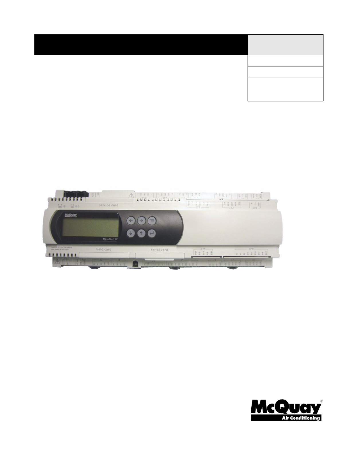
MicroTech® II Unit Controls
For Maverick II™ Commercial Packaged
Rooftop Systems
Models MPS020E – 050E
20 to 50 Tons
R-410A Refrigerant
Group: Applied Systems
Part Number: OM 843
Date: August 2009
© 2009 McQuay International
Page 2

Page 3

Contents
Introduction . . . . . . . . . . . . . . . . . . . . . . . . . . . . . . . 2
Agency Listed . . . . . . . . . . . . . . . . . . . . . . . . . . . . 2
Keypad Functions . . . . . . . . . . . . . . . . . . . . . . . . . . 3
Keypad/Display Menu Structure. . . . . . . . . . . . . . . 4
Menu Summary . . . . . . . . . . . . . . . . . . . . . . . . . . . . 6
Standard Menu Structure . . . . . . . . . . . . . . . . . . . 12
System Menu. . . . . . . . . . . . . . . . . . . . . . . . . . . . 14
Occupancy. . . . . . . . . . . . . . . . . . . . . . . . . . . . . . 16
Temperatures . . . . . . . . . . . . . . . . . . . . . . . . . . . 17
Duct Pressure . . . . . . . . . . . . . . . . . . . . . . . . . . . 18
Bldg Pressure . . . . . . . . . . . . . . . . . . . . . . . . . . . 19
Stgd Exh Fans . . . . . . . . . . . . . . . . . . . . . . . . . . . 19
Heating . . . . . . . . . . . . . . . . . . . . . . . . . . . . . . . . 20
Zone Cooling . . . . . . . . . . . . . . . . . . . . . . . . . . . . 21
Disch Cooling . . . . . . . . . . . . . . . . . . . . . . . . . . . 22
Alarms. . . . . . . . . . . . . . . . . . . . . . . . . . . . . . . . . . . 24
Alarm Out Faults . . . . . . . . . . . . . . . . . . . . . . . . . 24
Alarm Problems . . . . . . . . . . . . . . . . . . . . . . . . . . 25
Alarm Warning. . . . . . . . . . . . . . . . . . . . . . . . . . . 25
Extended Menus . . . . . . . . . . . . . . . . . . . . . . . . . . 26
Password. . . . . . . . . . . . . . . . . . . . . . . . . . . . . . . 26
Condenser Fans . . . . . . . . . . . . . . . . . . . . . . . . . 28
Economizer . . . . . . . . . . . . . . . . . . . . . . . . . . . . . 28
Min OA Damper. . . . . . . . . . . . . . . . . . . . . . . . . . 29
Daily Schedule. . . . . . . . . . . . . . . . . . . . . . . . . . . 32
Holiday Schedule. . . . . . . . . . . . . . . . . . . . . . . . . 32
One Event Sched . . . . . . . . . . . . . . . . . . . . . . . . 33
Optimal Start . . . . . . . . . . . . . . . . . . . . . . . . . . . . 33
Setup . . . . . . . . . . . . . . . . . . . . . . . . . . . . . . . . . . 34
Time Settings. . . . . . . . . . . . . . . . . . . . . . . . . . . . 34
Time/Date . . . . . . . . . . . . . . . . . . . . . . . . . . . . . . 35
Stgd Exh Fan Setup . . . . . . . . . . . . . . . . . . . . . . 35
Heating Setup . . . . . . . . . . . . . . . . . . . . . . . . . . . 36
Cooling Setup . . . . . . . . . . . . . . . . . . . . . . . . . . . 37
Operating Hours . . . . . . . . . . . . . . . . . . . . . . . . . 38
Manual Control . . . . . . . . . . . . . . . . . . . . . . . . . . 39
Alarm Limits. . . . . . . . . . . . . . . . . . . . . . . . . . . . . 40
Hidden Data Menus . . . . . . . . . . . . . . . . . . . . . . . . 41
Unit Configuration Setup Menu . . . . . . . . . . . . . . 41
Network Configuration . . . . . . . . . . . . . . . . . . . . . 42
Economizer Control . . . . . . . . . . . . . . . . . . . . . . . 43
Duct Static Pressure Control . . . . . . . . . . . . . . . . 43
Building Static Pressure Control . . . . . . . . . . . . . 44
Project Ahead Time - Zone Control . . . . . . . . . . . 44
Time Settings. . . . . . . . . . . . . . . . . . . . . . . . . . . . 44
Operating Hours Config Menu . . . . . . . . . . . . . . . 45
Remote Alarm Output Configuration . . . . . . . . . . 45
Alarm Delays . . . . . . . . . . . . . . . . . . . . . . . . . . . . 46
Controller . . . . . . . . . . . . . . . . . . . . . . . . . . . . . . . . 47
General Description. . . . . . . . . . . . . . . . . . . . . . . 48
Control Panel. . . . . . . . . . . . . . . . . . . . . . . . . . . . 48
Unit Controller . . . . . . . . . . . . . . . . . . . . . . . . . . . 50
Field Wiring . . . . . . . . . . . . . . . . . . . . . . . . . . . . . . 56
Field Output Signal . . . . . . . . . . . . . . . . . . . . . . . 56
Field Input Signal. . . . . . . . . . . . . . . . . . . . . . . . . 57
Loading New Application Code . . . . . . . . . . . . . . 58
Typical Wiring Diagrams . . . . . . . . . . . . . . . . . . . . 60
Page 4
Introduction
Introduction
This manual provides information regarding the MicroTech® II control system used in the
McQuay Commercial Packaged Rooftop Unit model MPS product line. It specifically
describes the operation and programmable options for units with constant air volume (CAV)
control and variable air volume (VAV) control.
Agency Listed
Note – LonMark and the LonMark Logo are managed, granted, and used by LonMark
International under a license granted by Echelon Corporation.
For installation and startup instructions and general information regarding a particular rooftop
unit, refer to the applicable model-specific installation and maintenance manual.
NOTICE
This equipment generates, uses, and can radiate radio frequency energy and,
if not installed and used in accordance with this instruction manual, may cause
interference to radio communications. It has been tested and found to comply
with the limits for a Class A digital device, pursuant to part 15 of the FCC rules.
These limits are designed to provide reasonable protection against harmful
interference when the equipment is operated in a commercial environment.
Operation of this equipment in a residential area is likely to cause harmful
interference in which case the user is required to correct the interference at his
own expense. McQuay International disclaims any liability resulting from
any interference or for the correction thereof.
WARNING
Electric shock hazard. Can cause personal injury or equipment damage.
This equipment must be properly grounded. Connections and service to the
MicroTech II control panel must be performed only by personnel that are
knowledgeable in the operation of the equipment being controlled.
WARNING
Excessive moisture in the control panel can cause hazardous working
conditions and improper equipment operation.
When servicing this equipment during rainy weather, the electrical
components in the main control panel must be protected from the rain.
2 McQuay OM 843-2
Page 5
Keypad Functions
CAUTION
Extreme temperature hazard. Can cause damage to system components.
The MicroTech II controller is designed to operate in ambient temperatures
from -20°F to 125°F. It can be stored in ambient temperatures from -40°F to
140°F. It is designed to be stored and operated in relative humidity up to 95%
(non-condensing).
CAUTION
Static sensitive components. A static discharge while handling
electronic circuit boards can cause damage to the components.
Discharge any static electrical charge by touching the bare metal inside the
main control panel before performing any service work. Never unplug any
cables, circuit board terminal blocks, relay modules, or power plugs while
power is applied to the panel.
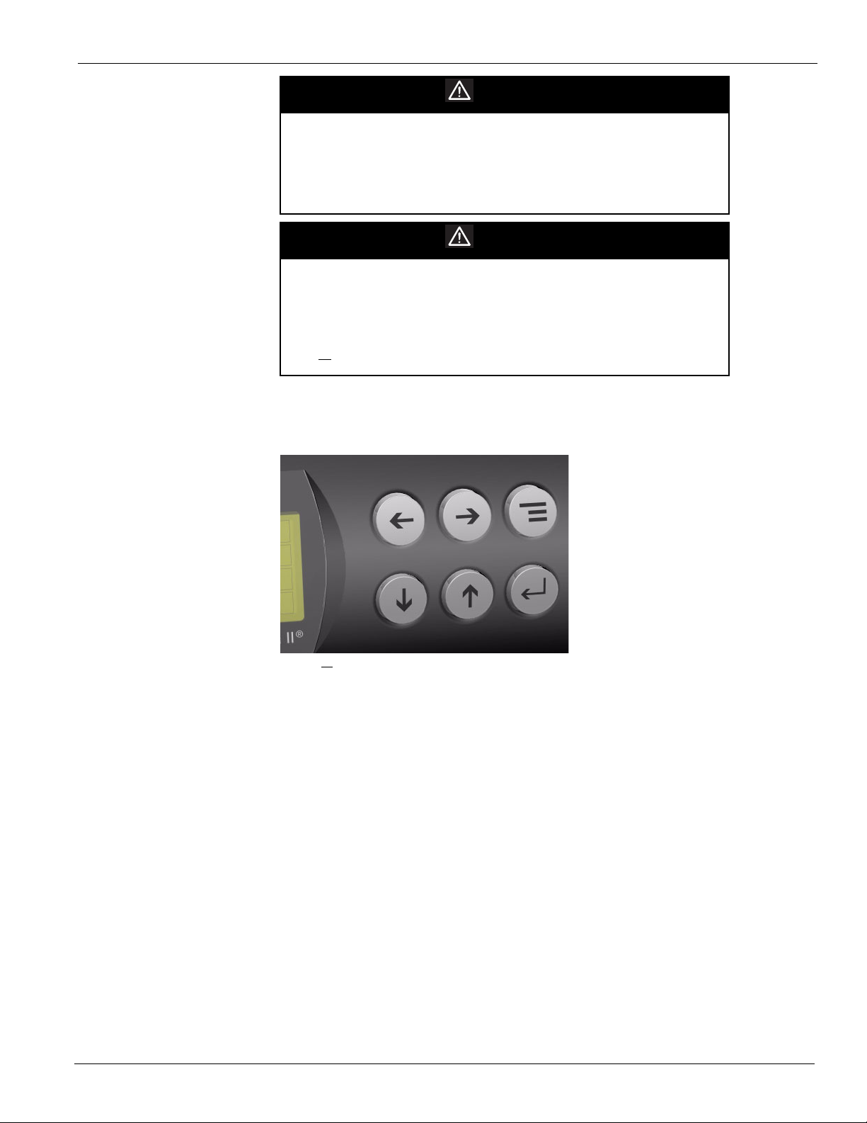
Keypad Functions
The keypad consists of six keys to control the navigation of the cursor through the menus.
Figure 1: Keypad Controls
Menu ( =) – pressing this key at any location within the menu structure (other than Edit mode)
will bring you to the beginning of the system menu. While in Edit mode, pressing it twice will
bring you to the system menu.
Up (
) – moves the cursor up the menu structure.
Down (
Right (
Left (
Enter (
this key after a field edit will also save the changed input value.
McQuay OM 843-2 3
) – moves the cursor down the menu structure.
) – moves the menu structure to the next available menu to the right.
) – moves the menu structure to the next available menu to the left.
) – pressing this key will allow the entry into a menu structure for editing. Pressing
Page 6
Keypad/Display Menu Structure
Active Alarm Alarm Log
No More Alarms
Press ENTER to clear
Alarm Log
Standard Menus
Occupancy
Occupanc y
Occ Mode
Occ Src
Tnt Ovrd Time
System Temperatures
Disch Air
Return Air
Space Temp
OA Temp
Duct Pressure
(VAV)
Supply Fan Cap
Duct Pres s
Duct SP Spt
DSP DB
SF Cap Ctrl
Remote SF Cap
Enter Password
For Extended Menus
Password = 4 5 4 5
Condenser Fan
Cond Fan 2 Spt
Cond Fan 3 Spt
Cond Fan 4 Spt
Cond Fan Di
Economizer
Economizer Po s
Disch Air
DAT Clg Spt
Min OA Po s
Chgover Temp
Chgover Di
Min OA Damper
Min OA Po s
Vent Limit
DCV Limi t
Design Clg Spd
Min Clg Spd
LoFlo Vent Limit
IAQ PPM
IAQ Spt
IAQ Deadband
Min OA Type
AI3 Cong
Daily Schedul e
Holiday
Schedule
Hol 1
Hol 2
Hol 3
Hol 4
Hol 5
Hol 6
Hol 7
Hol 8
Hol 9
Hol 10
Hol 11
Hol 12
Mon
Tu e
We d
Th u
Fr i
Sat
Su n
Hol
Time/ Date
Time
Date
Da y
Operating Hours
Supply Fa n
Exhaust Fan
Mech Cool
Comp # 1
Comp # 2
Comp # 3
Comp # 4
Heatin g
Economizer
Stgd Exh Fan
Setu p
Exh Fan #1 On
Exh Fan #1 Of f
Exh Fan #2 On
Exh Fan #2 Of f
Exh Fan #3 On
Exh Fan #3 Of f
Tnt Override
Heating Setup
Unocc Htg Spt
Unocc Di
Ctrl Temp Src
OAT Htg Lock
OAT Lock Di
Stage Time
Cooling Setup
Unocc Clg Spt
Unocc Di
Ctrl Temp Src
OAT Clg Lock
OAT Lock Di
Stage Time
Unit Status
Op Status
Ctrl Mode
Clg Status
Htg Status
Econ Status
Clg Capacit y
Htg Capacity
OA Damper Pos
`
Emerg Mode
Appl Mode
Esc
No More Alarms
Press ENTER to clear
all active Alarms
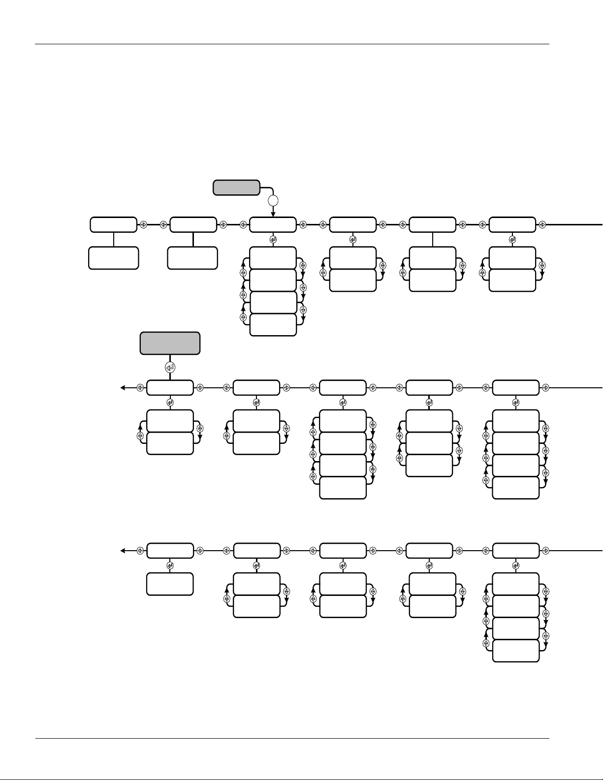
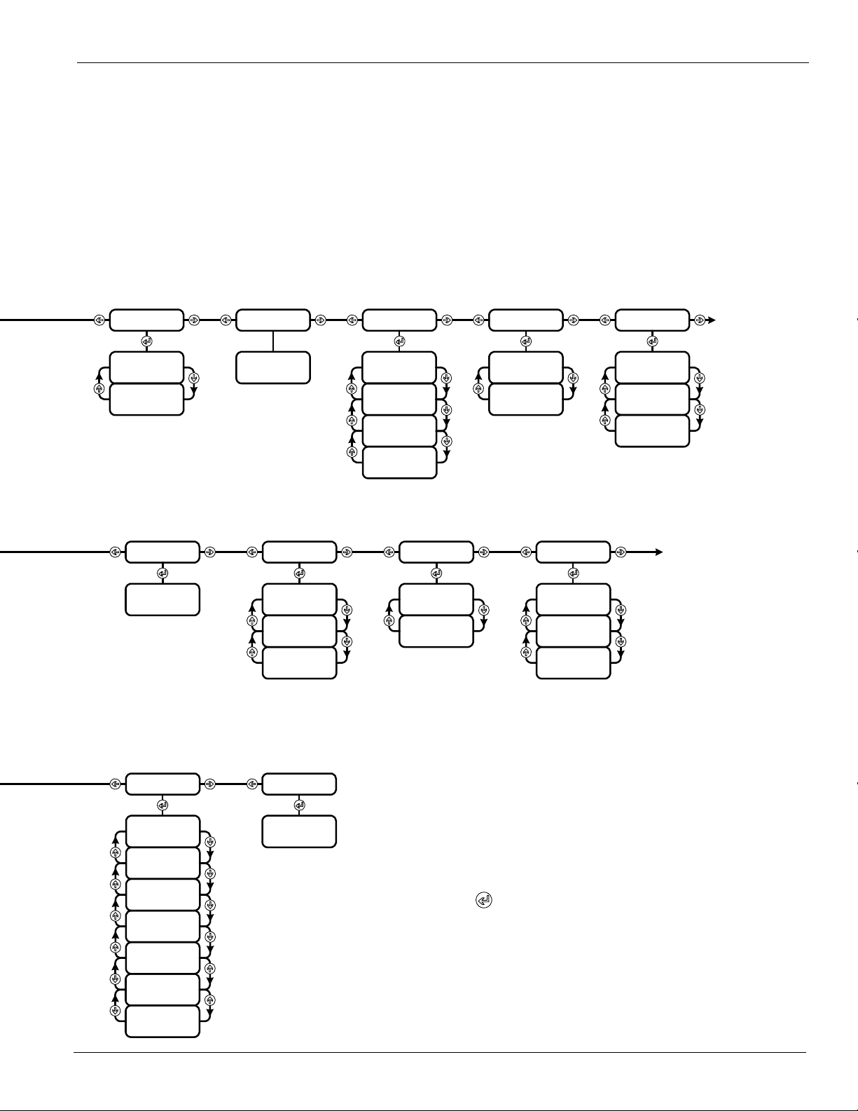
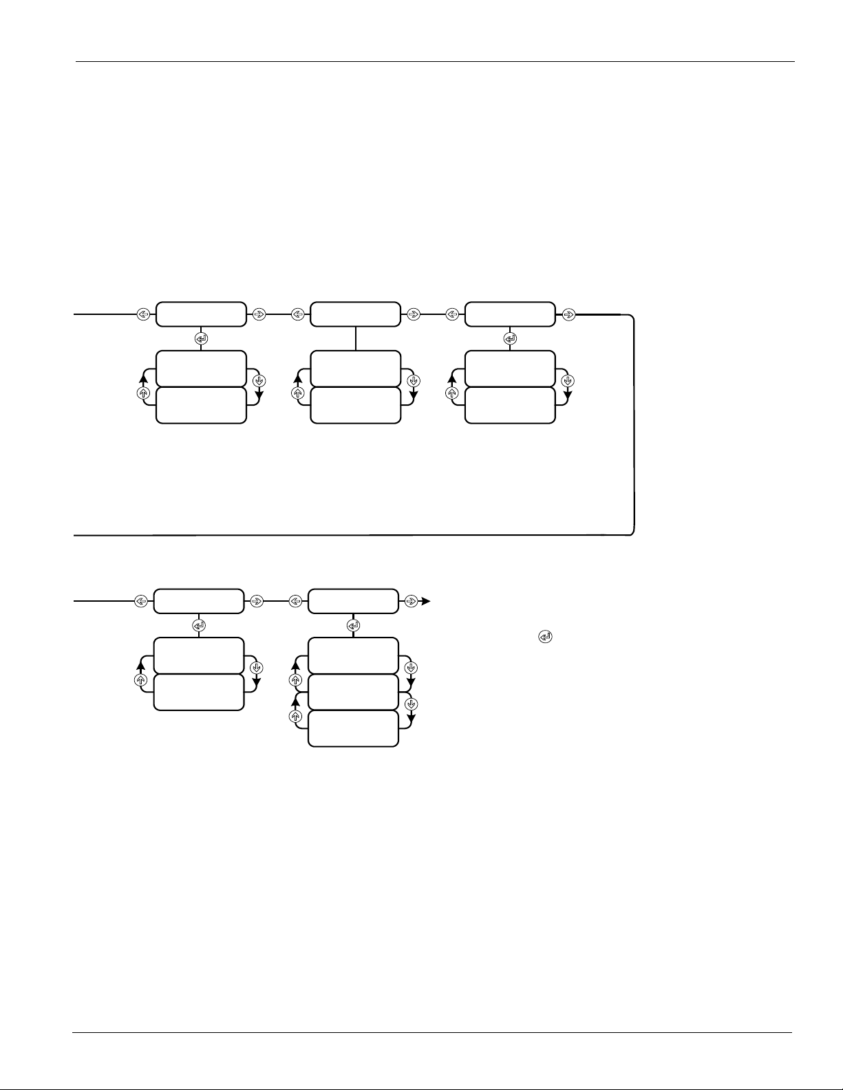
Keypad/Display Menu Structure
The following is a description of each menu and menu item within the rooftop MicroTech II
menu structure. Tables are included which show every menu, item, and field in the menu
structure of the program. These menus and items can all be displayed with the keypad/display.
The keypad display menus are divided into two sections. The first section is the standard
menus which do not require a password to gain access. The second section is the extended
menus which do require a password (“4545”, see Figure 2) to gain access.
Figure 2: Keypad/Display Menu Structure
4 McQuay OM 843-2
Page 7
Keypad/Display Menu Structure
Bldg Pressure
Exh Fan Cap
Bldg Pres s
Bldg SP Sp t
BSP DB
EF Cap Ctrl
Remote EF Cap
Stgd Exh Fans
(CAV )
Exh Fan Cap
Heating
Control Temp
Heating Spt
Heating DB
Heating Type
Heating Cap
Zone Cooling
(CAV )
Control Temp
Cooling Spt
Cooling DB
Min DAT Spt
Disch Cooling
(VAV )
One Event
Sched
Beg
End
Optimal Star t
Enable
Space Temp
OA Temp
Htg Rate
Htg OAT
Design Htg OAT
Clg Rate
Clg OAT
Design Clg OAT
Setu p
AI1
Space T Present
Units
BO 9
Manual Control
Supply Fa n
Comp # 1
Comp # 2
Comp # 3
Comp # 4
Cond Fan # 2
Cond Fan # 3
Alarm Ou t
VAV/ Fan Op Out
Heat # 4
Exh Fan # 1
Exh Fan # 2
Sup Fan Spd
Exh Fan Sp d
OA Damper Pos
Manual Control
Heat # 1
Heat # 2
Heat # 3
Alarm Limits
Hi Disch Alm
Lo Disch Alm
Hi Return Alm
Time Settings
Service
Start Up
Recirculate
Zero OA Time
Tnt Override
Post Heat
Password
Notes
1. Your display may not show all of these menus.
Only the menus that apply to this congured unit will
be available.
2. Hit Return to scroll through changeable
variable on the current page .
3. When no alarm is active, hitting the menu key when
curser is at page header will return you to the
System page. When any alarm is active, hitting the
menu key will return you to the alarm page.
4. Hitting the menu key when curser is not at page header
will return you to the top of that page.
Disch Air
DAT Clg Spt
Clg Reset
DAT Clg DB
Control Temp
Chgover Sp t
Chgover DB
`
Min DAT Ctrl (VAV only)
Min DAT Limit (CAV only)
Min DAT Spt
Occ Heating (CAV only)
Disch Air (Modulating only)
DAT Mtg Spt (Mod. only)
DAT Htg DB (Mod. only)
McQuay OM 843-2 5
Page 8
Menu Summary
Menu Summary
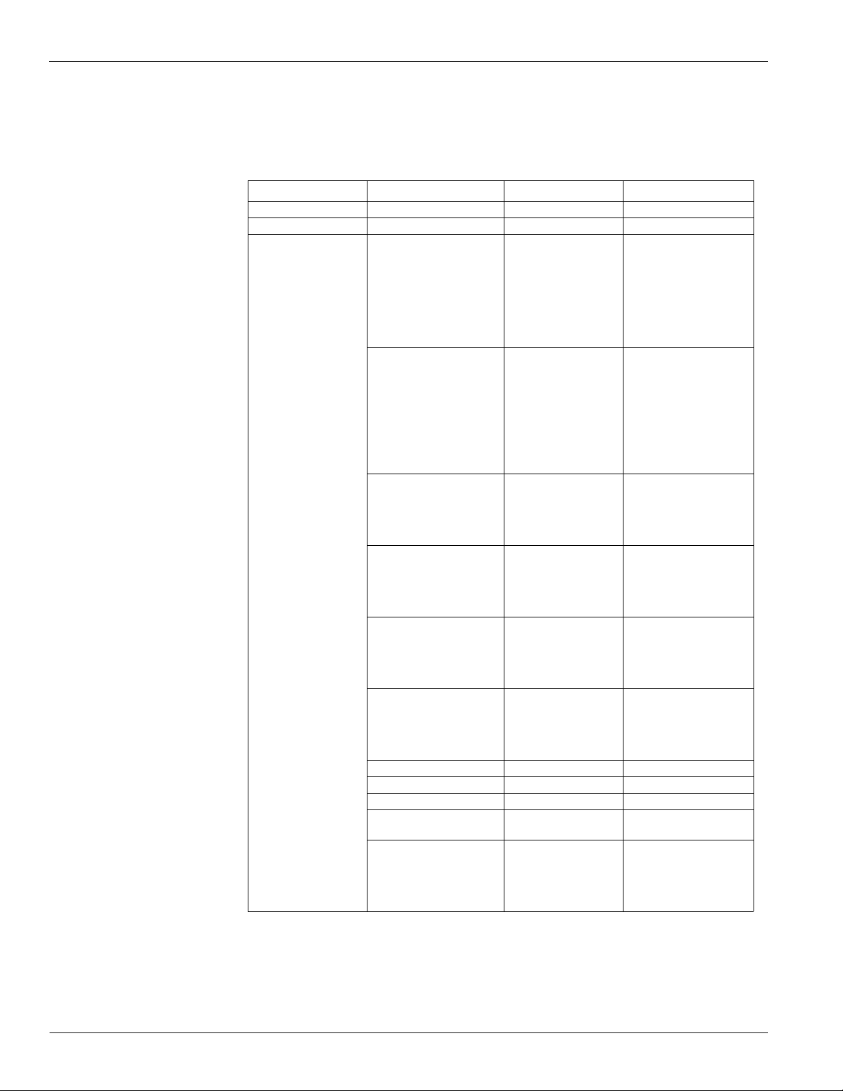
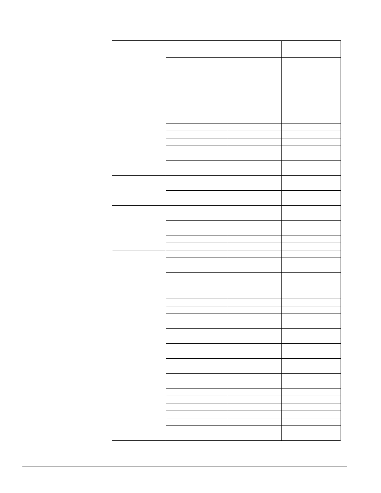
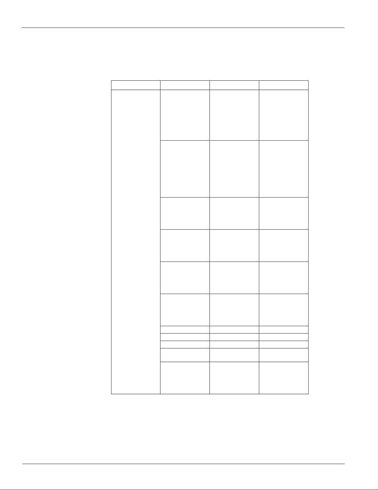
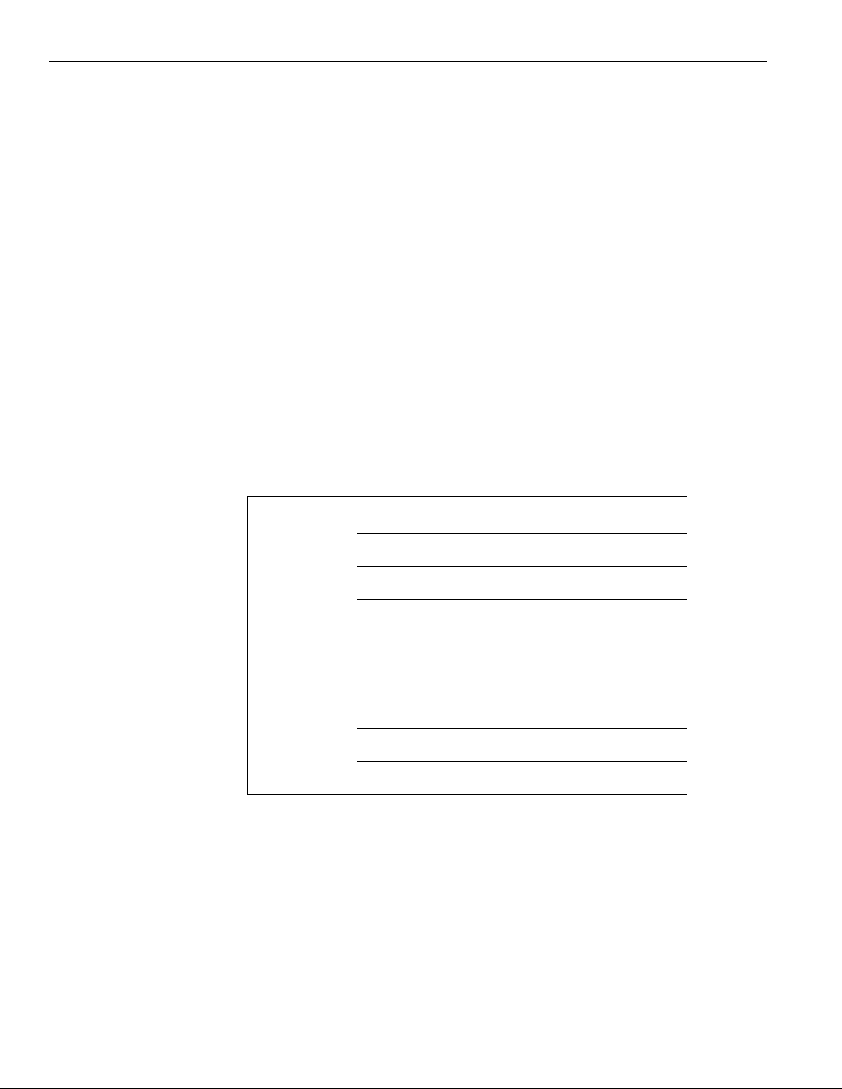
Table 1 lists basic unit operating status and control set point parameters. The “Range” column
in the table lists all possible values for each item. The factory settings for the adjustable
parameters are shown in the “Default” column.
Table 1: Menu Summary
Menu Menu Item Default Range
Active Alarm
Alarm Log
Off
Startup
Recirc
Fan Only
Min DAT
Heating
Econo
Cooling
Off Unocc
Unocc Op
Tnt Ovrd
Occ Op
Off Net
Off Alm
Off Man
Off Man Ctrl
Off Emerg
Off
Auto
Heat Only
Cool Only
Fan Only
Enabled
Off Man
Off Net
Off Alm
Off Amb
Enabled
None
Off Man
Of Net
Off Amb
Enabled
None
Off Man
Off Net
Off Amb
Normal
Shutdown
Off
Heat Only
Cool Only
Fan Only
Heat/Cool
System
Unit Status= -
Op Status=
Ctrl Mode= Off
Clg Status= -
Htg Status= -
Econo Status= -
Clg Capacity= - 0 - 100%
Htg Capacity= - 0 - 100%
OA Damper Pos= - 0 - 100%
Emerg Mode=
Appl Mode= Heat/Cool
-
6 McQuay OM 843-2
Page 9
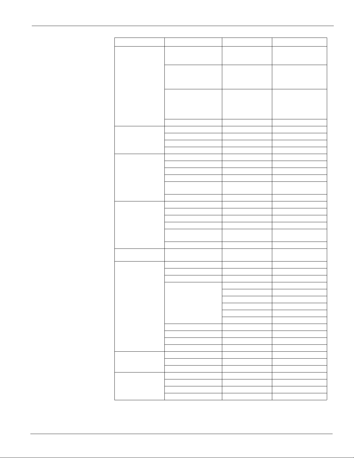
Table 1: Menu Summary (continued)
Menu Menu Item Default Range
Occupancy= -
Occ Mode= Auto
Occupancy
Occ Src=
Tnt Ovrd Time= 0 min 0 - 300
Disch Air= - -45 - 212
Temperatures
Duct Pressure
Bldg Pressure (Exh Fan
Ctrl=VFD)
StgdExh Fans (Exh Fan
Ctrl=Stgd)
Heating (Any Heat)
Mod Gas
Zone Cooling (CAV)
Return Air= - -45 - 212
Space Temp= - -45 - 212
OA Temp= - -45 - 212
Supply Fan Cap= - 0 - 100
Duct Press= - 0 - 5
DuctSP Spt= 1.00IWC .20 - 4.00
DSP DB= 0.1IWC .02 - .400
SF Cap Ctrl= DuctPres
Remote SF Cap= 25% 25 - 100
Exh Fan Cap= - 0 - 100
Bldg Press= - -.25 - .25
BldgSp Spt= .050IWC -.250 - .250
BSP DB= .010IWC .001 - .100
EF Cap Ctrl= Bldg Pres
Remote EF Cap= 25% 25 - 100
Exh Fan Cap= - 0 - 100
Control Temp= - -45 - 212
Heating Spt= 70°F 32 - 100
Heating DB 2.0°F 1.0 - 9.9
Heating Type=
Min DAT Ctrl=(VAV Only) No No/Yes
Min DAT Limit=(CAV Only) 55°F 32 - 99.9
Max DAT Spt= 105°F 50.0 - 120.0
Occ Heating=(VAV Only) Always MWU/Always
Disch Air=
DAT Htg Spt= 100°F 0.0 - 120.0
DAT Htg DB= 2.0°F 1.0 - 9.9
Control Temp= - -45 - 212
Cooling Spt= 75.0°F 40.0 - 99.0
Cooling DB= 2.0°F 1.0 - 9.9
Min DAT Setpt= 55.0°F 40.0 - 99.0
Menu Summary
Occ
Unocc
Tnt Ovrd
Auto
Occ
Unocc
Tnt Ovrd
Int Sched
Ts ta t
Remote Sw
Network
Occ Mode
DuctPres
Speed
Bldg Pres
Speed
None
2 Stg
4 Stg
ModLoGas
ModHiGas
Mod Water
McQuay OM 843-2 7
Page 10
Menu Summary
Table 1: Menu Summary (continued)
Menu Menu Item Default Range
Disch Air= - -45 - 212
DAT Clg Spt= 55.0°F 50.0 - 99.0
Clg Reset= None
Discharge Cooling
(VAV )
Condenser Fans
Economizer (Automatic
or CAV)
Min OA Damper
Daily Schedule
DAT Clg DB= 2.0°F 1.0 - 9.9
Min Clg Spt= 55.0°F 50.0 - 99.0
Min Clg Spt @ 0.0 0.0 - 100.0
Max Clg Spt= 65.0°F 50.0 - 99.0
Max Clg Spt @ 100.0 0.0 - 100.0
Control Temp= - -45 - 212
Chgover Spt= 75.0°F 32.0 - 99.0
Chgover DB= 2.0°F 1.0 - 9.9
Cond Fan 2 Spt= - 0 - 104
Cond Fan 3 Spt= - 0 - 104
Cond Fan 4 Spt= - 0 - 104
Cond Fan Diff= 5.0°F 5 - 20
Economizer Pos= - 0 - 100
Disch Air= - -45 - 212
DAT Clg Spt= 55.0°F 50.0 - 99.0
Min OA Pos= - 0 - 100
Chgover Temp= 60°F 32.0 - 99.0
Chgover Diff= 10.0°F 5 - 20
Min OA Pos= - 0 - 100
Vent Limit= 20% 1 - 99
DCV Limit= 10% 1 - 99
Min OA Type= None
xx.x% @ DCV Limit 0 0 - 100
xx.x% @ Vent Limit 100 0 - 100
Ext Percent = - 0 - 100
0% @ xx V/mA 4 mA 0 - 20
100% @ xx V/mA 20 mA 0 - 20
xxxx PPM @ DCV Limit 800 0 - 9999
xxxx PPM @ Vent Limit 1000 0 - 9999
xxxx PPM @ xx V/mA 0 4mA 0 - 9999
xxxx PPM @ xx v/mA 2000 20mA 0 - 9999
Min Clg Spd= 40% 1 - 99
LoFlo Vent Limit= 30% 1 - 99
Mon= 00:00 - 00:00 00:00 - 23:59
Tue= 00:00 - 00:00 00:00 - 23:59
Wed= 00:00 - 00:00 00:00 - 23:59
Thu= 00:00 - 00:00 00:00 - 23:59
Fri= 00:00 - 00:00 00:00 - 23:59
Sat= 00:00 - 00:00 00:00 - 23:59
Sun= 00:00 - 00:00 00:00 - 23:59
Hol= 00:00 - 00:00 00:00 - 23:59
None
Network
Space
Return
OAT
Airflow
Ext mA
Ext V
None
Network
External
IAQ
8 McQuay OM 843-2
Page 11
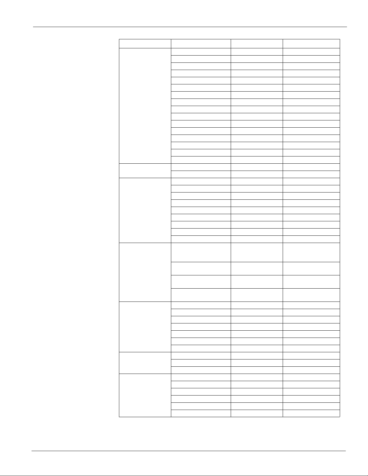
Table 1: Menu Summary (continued)
Menu Menu Item Default Range
Hol 1= NA 00 - NA 00 Jan-Dec 0-31
Hol 2= NA 00 - NA 00 Jan-Dec 0-31
Hol 3= NA 00 - NA 00 Jan-Dec 0-31
Hol 4= NA 00 - NA 00 Jan-Dec 0-31
Hol 5= NA 00 - NA 00 Jan-Dec 0-31
Hol 6= NA 00 - NA 00 Jan-Dec 0-31
Hol 7= NA 00 - NA 00 Jan-Dec 0-31
Holiday Schedule
One Event Sched
Optimal Start
Setup
Time Settings
Time/Date
StgdExh Fan Setup
Hol 8= NA 00 - NA 00 Jan-Dec 0-31
Hol 9= NA 00 - NA 00 Jan-Dec 0-31
Hol 10= NA 00 - NA 00 Jan-Dec 0-31
Hol 11= NA 00 - NA 00 Jan-Dec 0-31
Hol 12= NA 00 - NA 00 Jan-Dec 0-31
Hol 13= NA 00 - NA 00 Jan-Dec 0-31
Hol 14= NA 00 - NA 00 Jan-Dec 0-31
Hol 15= NA 00 - NA 00 Jan-Dec 0-31
Hol 16= NA 00 - NA 00 Jan-Dec 0-31
Beg= NA 00 @ 00:00 Jan-Dec 00:00 - 23:59
End= NA 00 @ 00:00 Jan-Dec 00:00 - 23:59
Enable= No No/Yes
Space Temp= - -45 - 212
OA Temp= - -45 - 212
Htg Rate= .400 .000 - .999
Htg OAT= 35°F -40 - 60
Design Htg OAT= 0°F -40 - 60
Clg Rate= .400 .000 - .999
Clg OAT= 85°F 60 - 140
Design Clg OAT= 95°F 60 - 140
AI1= RAT
Space T Present= Yes
Units= English
B09= Fan Op Output
Service= 0 min 0 - 240
Start Up= 180 sec 0 - 240
Recirculate= 180 sec 120 - 3600
Zero OA Time= 90 min 0 - 240
Tnt Override= 120 min 0 - 300
Post Heat= 0 sec 0 - 180
Password= 15 min 5 - 60
Time= - 00:00 - 23:59
Date= - Jan-Dec 0-31 2000-2009
Day= - Sunday - Saturday
Exh Fan # 1 On= 40% 0 - 99
Exh Fan # 1 Off= 30% 0 - 99
Exh Fan # 2 On= 55% 0 - 99
Exh Fan # 2 Off= 40% 0 - 99
Exh Fan # 3 On= 70% 0 - 99
Exh Fan # 3 Off= 50% 0 - 99
Menu Summary
None
RAT
SpaceSpt
No
Yes
English
Metric
Fan Op Output
VAV O ut pu t
McQuay OM 843-2 9
Page 12
Menu Summary
Table 1: Menu Summary (continued)
Menu Menu Item Default Range
Unocc Htg Spt= 55.0°F 32.0 - 99.0
Unocc Diff= 3.0°F 1.0 - 9.9
Heating Setup
Cooling Setup
Operating Hours
CtrlTemp Scr= Return
OAT Htg Lock= 2.0°F 1.0 - 99.0
OAT Lock Diff
Stage Time= 5 min 4 - 60
Unocc Clg Spt= 55.0°F 32.0 - 99.0
Unocc Diff= 3.0°F 1.0 - 9.9
CtrlTemp Scr= Return
OAT Clg Lock= 2.0°F 1.0 - 99.0
OAT Lock Diff=
Stage Time= 5 min 4 - 60
Supply Fan= 000,000 0 - 999999
Exhaust Fan= 000,000 0 - 999999
Mech Cool= 000,000 0 - 999999
Comp # 1 = 000,000 0 - 999999
Comp # 2 = 000,000 0 - 999999
Comp # 3 = 000,000 0 - 999999
Comp # 4 = 000,000 0 - 999999
Heating= 000,000 0 - 999999
Economizer= 000,000 0 - 999999
Tnt Override= 000,000 0 - 999999
Return
Space
Return
Space
10 McQuay OM 843-2
Page 13
Table 1: Menu Summary (continued)
Menu Menu Item Default Range
Manual Ctrl= Off
Supply Fan= Off
Comp # 1 = Off
Comp # 2 = Off
Comp # 3 = Off
Comp # 4 = Off
Cond Fan # 2 = Off
Cond Fan # 3 = Off
Heat # 1 = Off
Manual Control
Alarm Limits
Heat # 2 = Off
Heat # 3 = Off
Heat # 4 = Off
Exh Fan # 1 = Off
Exh Fan # 2 = Off
Alarm Out= Off
Vav/Fan Op Out= Off
Sup Fan Spd= 0.0% 0.0 - 100.0
Exh Fan Spd= 0.0% 0.0 - 100.0
OA Damper Pos= 0.0% 0.0 - 100.0
Htg Mod VLV 0 0.0 - 100.0
Hi Disch Alm= 170 90 - 250
Lo Disch Alm= 40 20 - 50
Hi Return Alm= 120 90 - 150
Menu Summary
On
Off
On
Off
On
Off
On
Off
On
Off
On
Off
On
Off
On
Off
On
Off
On
Off
On
Off
On
Off
On
Off
On
Off
On
Off
On
Off
McQuay OM 843-2 11
Page 14
Standard Menu Structure
Active Alarm Alarm Log
No More Alarms
Press ENTER to clear
Alarm Log
Standard Menus
System
Unit Status
Op Status
Ctrl Mode
Clg Status
Htg Status
Econ Status
Clg Capacit y
Htg Capacity
OA Damper Pos
`
Emerg Mode
Appl Mode
Esc
No More Alarms
Press ENTER to clear
all active Alarms
Bldg Pressure
Exh Fan Cap
Bldg Pres s
Bldg SP Sp t
BSP DB
EF Cap Ctrl
Remote EF Cap
Stgd Exh Fans
(CAV )
Exh Fan Cap
Heating
Control Temp
Heating Spt
Heating DB
Heating Type
Heating Cap
Min DAT Ctrl (VAV only)
Min DAT Limit (CAV only)
Min DAT Spt
Occ Heating (CAV only)
Disch Air (Modulating only)
DAT Mtg Spt (Mod. only)
DAT Htg DB (Mod. only)
Standard Menu Structure
The Standard Menus are menu items that control the unit's day to day operation. The menus
provide information about the units operation and its control parameters.
Figure 3: Keypad Standard Menu Structure
12 McQuay OM 843-2
Page 15
Standard Menu Structure
Occupancy
Occupanc y
Occ Mode
Occ Src
Tnt Ovrd Time
Temperatures
Disch Air
Return Air
Space Temp
OA Temp
Duct Pressure
(VAV)
Supply Fan Cap
Duct Pres s
Duct SP Spt
DSP DB
SF Cap Ctrl
Remote SF Cap
Zone Cooling
(CAV )
Control Temp
Cooling Spt
Cooling DB
Min DAT Spt
Disch Cooling
(VAV )
Disch Air
DAT Clg Spt
Clg Reset
DAT Clg DB
Control Temp
Chgover Sp t
Chgover DB
`
Notes
1. Your display may not show all of these menus.
Only the menus that apply to this congured unit will
be available.
2. Hit Return to scroll through changeable
variable on the current page .
3. When no alarm is active, hitting the menu key when
curser is at page header will return you to the
System page. When any alarm is active, hitting the
menu key will return you to the alarm page.
4. Hitting the menu key when curser is not at page header
will return you to the top of that page.
McQuay OM 843-2 13
Page 16
Standard Menu Structure
System Menu
The “System” menu provides a summary of basic unit status and control items. This menu
summarizes the current operating state of the unit, giving the operating state the unit is in,
along with the current capacity level of that operating state.
Table 2: System Menu
Menu Menu Item Default Range
System
Off
Startup
Recirc
Unit Status= -
Op Status=
Ctrl Mode= Off
Clg Status= -
Htg Status= -
Econo Status= -
Clg Capacity= - 0 - 100%
Htg Capacity= - 0 - 100%
OA Damper Pos= - 0 - 100%
Emerg Mode= Normal
Off
Heat Only
Appl Mode=
Cool Only
Fan Only
Heat/Cool
Fan Only
Min Dat
Heating
Econo
Cooling
Off Unocc
Unocc Op
Tnt Ovrde
Occ Op
Off Net
Off Alrm
Off Man
Off Man Ctrl
Off Emerg
Off
Auto
Heat/Cool
Cool Only
Fan Only
Enabled
Off Man
Off Net
Off Alm
Off Amb
Enabled
None
Off Man
Of Net
Off Amb
Enabled
None
Off Man
Off Net
Off Amb
Normal
Shutdown
14 McQuay OM 843-2
Page 17
Standard Menu Structure
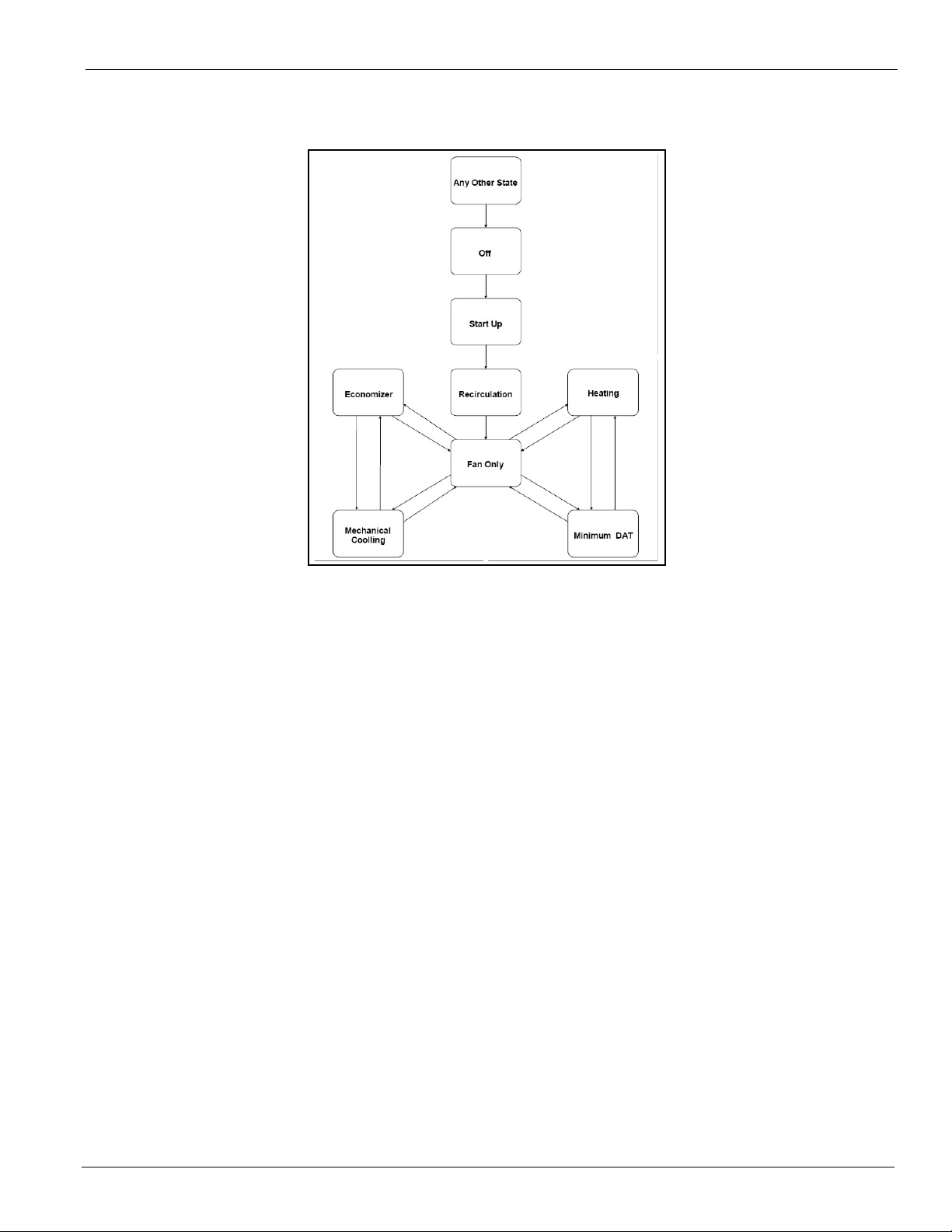
UnitStatus= is a status only item which indicates the state of operation in which the unit is
currently operating. The unit can be in any of the operating states shown in Figure 4.
Figure 4: State Diagram
The transition from any operating state to another is also graphically represented in this figure.
With a “start up” command from an Off State the unit will always go into the “Start Up” state
of operation for 3 minutes. Next, it will transition into the “Recirculation” state of operation
for another 3 minutes before finally going into the Fan Only state of operation. Then, based on
sensor inputs it will go into any of the 4 remaining states of operation - heating, cooling,
economizer, or minimum discharge air heating.
OpStatus= is a status only item which indicates the operating status of the unit. This menu
item will indicate why the unit is running or why the unit is off.
Ctrl Mode= is an adjustable item which allows the unit to be set for off, auto heating/cooling
operation, cooling only, heating only, and fan only.
Clg Status= is a status only item which indicates whether or not cooling (economizer and/or
mechanical) is currently allowed. If cooling is disabled, the reason is indicated.
Htg Status= is a status only item which indicates whether or not heating is currently allowed.
If heating is disabled, the reason is indicated.
EconoStatus= is a status only item which indicates whether or not the economizer is enabled
Clg Capacity= is a status only item which indicates the percentage of the unit maximum
cooling capacity currently operating.
Htg Capacity= is a status only item which indicates the percentage of the unit maximum
heating capacity currently operating.
OA Damper Pos= is a status only item which indicates the percentage that the outdoor
damper is currently open.
EmergMode= is a status only item which indicates if the unit was shut down in an emergency
situation.
Appl Mode= is a network adjustable item which indicates that the unit is set for network off,
cooling only, heating only, fan only or auto heating/cooling operation via a network signal.
This item has no affect on the unit operation unless the Ctrl Mode= item is set to “Auto”.
McQuay OM 843-2 15
Page 18
Standard Menu Structure
Occupancy
Menus in the Occupancy menu contain status and control items that relate to unit
occupied/unoccupied operation.
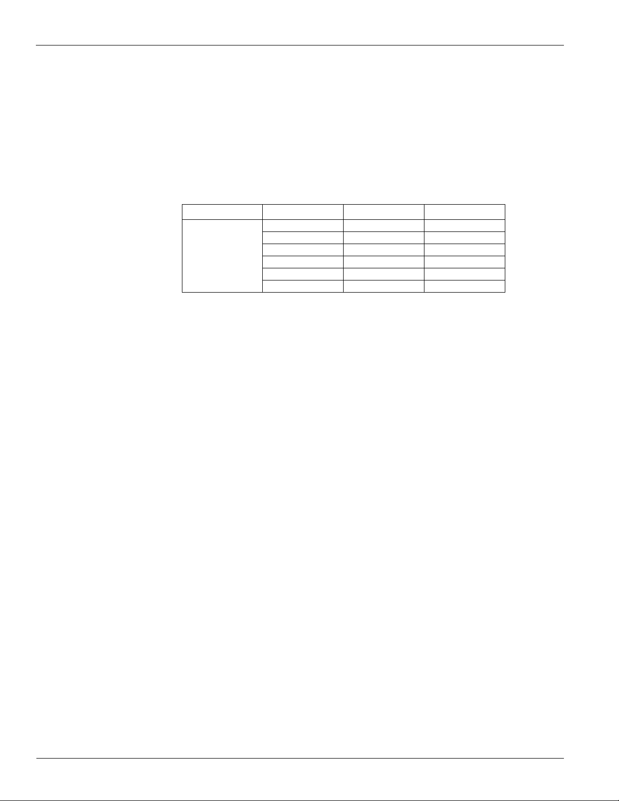
Table 3: Occupancy Menu
Menu Menu Item Default Range
Occupancy
Occupancy= is a status only item which indicates whether the unit is currently in an occupied,
unoccupied, or tenant override mode of operation.
OccMode= is an adjustable item which allows the unit to be set for manual occupied or
unoccupied operation, automatic operation based on a time schedule input or manual bypass
operation.
OccSrc= is a status only item which indicates the input source or function that is responsible
for setting the Occupancy= parameter to “Occ”.
Tnt Ovrd= is a status only item which indicates the amount of time remaining for unit
operation since the tenant override button was activated.
Occupancy= -
Occ Mode= Auto
Occ Src=
Tnt Ovrde Time= 120min 0 - 300
Occ
Unocc
Tnt Ovrd
Auto
Occ
Unocc
Tnt Ovrd
Int Sched
Ts ta t
Remote Sw
Network
Occ Mode
16 McQuay OM 843-2
Page 19

Standard Menu Structure
Temperatures
Menus in the Temperatures menu contain unit temperature status information.
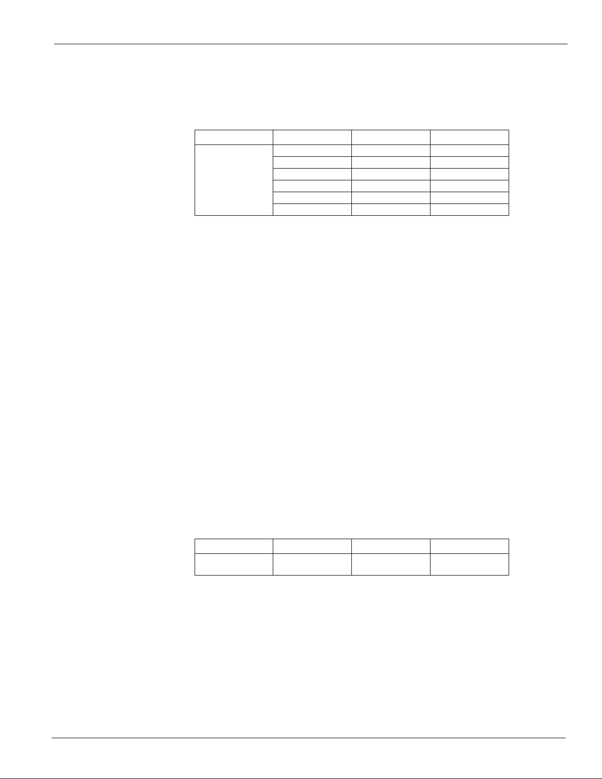
Table 4: Temperatures Menu
Menu Menu Item Default Range
Disch Air= - -45 - 212
Temperatures
Disch Air = is a status only item which displays the current temperature reading from the
unit's discharge air temperature sensor (DAT). This sensor is standard on all units.
Return Air= is a status only item which displays the current temperature reading from the
unit's return air temperature sensor (RAT). This sensor is standard on all units.
Space Temp= is a status only item which displays the current space (or zone) temperature
reading from the optional unit space air temperature sensor input.
If an optional space temperature sensor is not installed, the SpaceT Present= item in the Setup
menu should be set to “No” to disable the alarm function associated with an open circuit at the
space temperature sensor input.
OA Temp= is a status only item which displays the current temperature reading from the unit
mounted outdoor air temperature sensor. This sensor is standard on all units.
Return Air= - -45 - 212
Space Temp= - -45 - 212
OA Temp= - -45 - 212
McQuay OM 843-2 17
Page 20
Standard Menu Structure
Duct Pressure
The Duct Pressure menu provides a summary of the duct pressure items and parameters
associated with variable air volume (VAV) fan control units. This menu is only available on
VAV units. The supply air fan speed in controlled by a VFD that is mounted in the control
cabinet. The control parameter for the fan speed is the duct static pressure setpoint. If the duct
static pressure is below the duct static pressure setpoint by more than ½ the deadband, the fan
speed will increase. Likewise if the duct static pressure is above the duct static pressure
setpoint by more than ½ the deadband the fan speed will decrease. Example - if the duct static
pressure setpoint is 1.2" and the deadband is 0.1", the duct static pressure must reach 1.14
before the fan will increase in speed.
Table 5: Duct Pressure Menu
Menu Menu Item Default Range
Duct Pressure
Supply Fan Cap= is a status only item which indicates the capacity of the supply air fan.
Duct Press= is a status only item which indicates the current pressure of the supply air
ductwork. The duct pressure is measured at the location in which the duct static pressure tap
was field installed. This device is not factory installed.
Supply Fan Cap= - 0 - 100
Duct Press= - 0 - 5
DuctSP Spt= 1.00IWC .20 - 4.00
DSP DB= 0.1IWC .02 - .400
SF Cap Ctrl= DuctPres DuctPres Speed
Remote SF Cap= 25% 25 - 100
Duct SP Spt= is an adjustable item which sets the duct static pressure set point used for
controlling the VFD for the supply air fan. The VFD is modulated to maintain the duct
pressure at this value.
DSP Db= is an adjustable item which sets a dead band around the DuctSP Spt= parameter. No
duct static pressure control action is taken when the current duct static pressure input is within
this dead band.
SF CAP Ctrl= is an adjustable parameter to control supply air fan by duct pressure or by a
percentage of supply air fan speed from 25% to 100%. The speed option is only used with a
building automation system.
Remote SF Cap= is an adjustable item for setting the supply fan speed by the keypad or by a
network control signal.
18 McQuay OM 843-2
Page 21
Standard Menu Structure
Bldg Pressure
The Building Pressure menu provides a summary of the control parameters for the exhaust
fans. This menu is only available on units with exhaust fans. The building pressure control
application can be on CAV or VAV units.
Table 6: Bldg Pressure Menu
Menu Menu Item Default Range
Exh Fan Cap= - 0 - 100
Bldg Press= - -.25 - .25
Bldg Pressure (Exh
Fan Ctrl=VFD)
Exh Fan Cap= is a status only item which indicates the capacity of the exhaust air fans.
Bldg Press= is a status only item which indicates the building static pressure at the building
static pressure sensor location.
Bldg SP Spt= is an adjustable item which sets the building static pressure set point used for
controlling the exhaust fan VFD. The Exhaust fan VFD is modulated to maintain the building
static pressure sensor input at this set point.
BSP DB= is an adjustable item which sets a dead band around the BldgSP Spt= parameter. No
building static pressure control action is taken when the current building static pressure input
is within this dead band.
BldgSp Spt= .050IWC -.250 - .250
BSP DB= .010IWC .001 - .100
EF Cap Ctrl= Bldg Pres Bldg Pres Speed
Remote EF Cap= 25% 25 - 100
EF Cap Ctrl= is an adjustable parameter to control how the exhaust fans are to be controlled.
The exhaust fans can be controlled by the building pressure or by a percentage of exhaust air
fan speed from 25% to 100%. The speed option is only used with a building automation
system.
Remote EF Cap= is an adjustable item for setting the exhaust fan speed by the keypad or by a
network control signal.
Stgd Exh Fans
The Staged Exhaust Fans menu provides a summary of the control parameters for the exhaust
fans. The staged exhaust fan control is only available on constant volume (CAV) units. The
capacity of the exhaust fans are controlled by the position of the economizer dampers. As the
OA damper position is increased the exhaust fans will stage up increasing in exhaust airflow
capacity.
Table 7: Stgd Exh Fans Menu
Menu Menu Item Default Range
Stgd Exh Fans (Exh
Fan Ctrl=Stgd)
Exh Fan Cap= is a status only menu to indicate the capacity of the exhaust air fans.
Exh Fan Cap= - 0 - 100
McQuay OM 843-2 19
Page 22
Standard Menu Structure
Heating
The Heating menu provides a summary of the control parameters for units with heating. The
unit's heating mode of operation is controlled by the control temperature and the heating
setpoint temperature. The unit goes into the heating mode of operation by analyzing the
control temperature. The control temperature can be either the return temperature or the space
temperature. The return temperature is typically used for VAV units and the space temperature
is typically used for CAV units. The unit goes into the heating mode of operation when the
control temperature (return or space temperature) is below the heating setpoint by more than ½
the deadband. Example - If the heating setpoint is 68.0°F and the deadband is 1.0°F, the unit
will not go into the heating mode of operation until the control temperature reaches 67.4°F.
When this occurs the heating mode of operation will begin and the 1st stage of heating
operation will start. The next stage up/down will take place after 4 minutes. This “4 minutes”
is called the stage timer. The gas heat module will continue to stage up as long as the control
temperature is below the heating setpoint by more than ½ the heating setpoint deadband. The
unit will stage down if the maximum discharge air temperature is reached. Units with one gas
valve have 2 stages of heating and units with two gas valves have 4 stages of heating.
Table 8: Heating Menu
Menu Menu Item Default Range
Heating (Any Heat)
Mod Gas
Control Temp= - -45 - 212
Heating Spt= 70°F 32 - 100
Heating DB 2.0°F 1.0 - 9.9
None
2 Stg
Heating Type=
Min DAT Ctrl (VAV
Only)=
Min DAT Limit (CAV
Only)=
Max DAT Spt= 105°F 50.0 - 120.0
Occ Heating (VAV
Only)=
Disch Air=
DAT Htg Spt= 100°F 0.0 - 120.0
DAT Htg DB= 2.0°F 1.0 - 9.9
No No/Yes
55°F 32 - 99.9
Always MWU/Always
4 Stg
ModLoGas
ModHiGas
ModWtr
Control Temp= is a status only item which indicates what the current control temperature is.
Heating Spt= is an adjustable item which sets the temperature in which the unit will go into
the heating mode of operation.
Heating DB= is an adjustable item which sets a deadband around the Heating Spt= parameter.
No heating control action (staging up or down) is taken when the control temperature is within
this deadband around the setpoint.
Heating Type= is a status only item. 1) 2 Stg - is the low heat option with a single furnace.
The furnace uses a two stage gas valve. 2) 4 Stg - is the high heat option with dual furnaces.
Each furnace uses a two stage valve. 3) ModLoGas - is the modulating low heat option with a
single furnace. The furnace uses a 25 - 100% modulating valve.4) ModHiGas - is the
modulating high heat option with dual furnaces. One furnace uses a 25 -100% modulating
valve and the other uses a 2 stage valve. 5) ModWtr - is the modulating hot water heat option.
Min DAT Ctrl (VAV Only)= is an adjustable item which sets the minimum that the discharge
air temperature can be. If the minimum is reached, the unit will stage up
20 McQuay OM 843-2
Page 23
Standard Menu Structure
Min DAT Limit (CAV Only)= is an adjustable item which sets the temperature on CAV units
in which the heating mode of operation will start if the DAT reaches this temperature.
Max DAT Spt= is an adjustable item which sets the maximum that the discharge air
temperature can be. If this maximum is reached then the unit will stage down.
Occ Heating (VAV Only)= is an adjustable item which allows a morning warm-up (MWU)
cycle or an Always heating mode cycle for the heating mode of operation. If MWU is used the
unit will only go into heating during the initial morning warm-up cycle. If Always is selected
the unit can go into the heating mode of operation any time of the day.
Disch Air= is a measurement of the temperature at the discharge air sensor during the heating
mode. It is used for modulating gas heat only.
DAT Htg Spt= is an adjustable item which sets the temperature of the discharge air when the
unit is in heating mode. It is used for modulating gas heat only.
DAT Htg DB= is an adjustable item which sets a deadband around the DAT Htg Spt=
parameter. No heating control action (staging up or down) is taken when the control
temperature is within this deadband around the setpoint. It is used for modulating gas heat
only.
Zone Cooling
The Zone Cooling menu provides a summary of the cooling control parameters for units with
constant air volume control only. These units are equipped with the space comfort control
(SCC) software.
The unit's cooling mode of operation is controlled by the control temperature and the cooling
setpoint. The control temperature for a CAV unit is typically the space temperature. A space
temperature sensor must be field installed into the occupied space and connected to the unit
controller. The unit goes into the cooling mode of operation when the control temperature
(space temperature) is above the cooling setpoint by more than ½ the deadband. Example - the
cooling setpoint is set to 70.0°F and the deadband is 1.0°F, the unit will not go into the cooling
mode of operation until the space sensor reaches 70.6°F. When this takes place the cooling
mode of operation will begin and the 1st stage of compressor operation will start. The unit
controller will turn on the next stage of compressor operation, or turn off a stage of
compressor operation, to maintain the cooling setpoint temperature within the deadband.
When a compressor stage turns on, the next compressor stage up or down will not take place
for the next 4 minutes. This “4 minutes” is called the stage time. Reference the Cooling Setup
menu for the adjustable stage time value. When a cooling stage is initiated no further operation
will take place within the stage timer limit. In the above example the unit will stage down or
turn off the cooling mode of operation when the cooling setpoint reaches 69.4°F.
Table 9: Zone Cooling Menu
Menu Menu Item Default Range
Control Temp= - -45 - 212
Zone Cooling (CAV)
Cooling Spt= 75.0°F 32.0 - 99.0
Cooling DB= 2.0°F 1.0 - 9.9
Min DAT Spt= 55.0°F 40.0 - 99.0
Control Temp= is a status only item which indicates what the current control temperature is.
Cooling Spt= is an adjustable item which sets the temperature in which the unit will go into
the cooling mode of operation.
Cooling DB= is an adjustable item which sets a deadband around the Cooling Spt= parameter.
No cooling control action (staging up or down) is taken when the control temperature is within
this deadband around the setpoint temperature.
Min DAT Spt= is an adjustable item which sets the minimum discharge air temperature
allowed when the unit is in zone cooling. When the unit is in zone cooling the staging of
McQuay OM 843-2 21
Page 24
Standard Menu Structure
compressors is controlled by the Cooling setpoint, 75°F. The unit controller is also analyzing
the discharge air temperature and will not allow operation below the Min DAT Spt.
Disch Cooling
The Discharge Cooling menu provides a summary to the cooling control parameters for units
with variable air volume (VAV) control. These units are equipped with the discharge air
control (DAC) software.
The unit's cooling mode of operation is controlled by the control temperature, the change over
temperature and the discharge air temperature. The unit goes into the cooling mode of
operation by analyzing the control temperature. The control temperature for a VAV system is
the return temperature. The unit goes into the cooling mode of operation when the control
temperature (return temperature) is above the change-over setpoint by more than ½ the
deadband. Example - If the change over temperature is 70.0°F and the deadband is 1.0°F, the
unit will not go into the cooling mode of operation until the return temperature reaches 70.6°F.
When this takes place the cooling mode of operation will begin and the 1st stage of
compressor operation will start. The unit controller will turn on the next stage of compressor
operation, or turn off a stage of compressor operation, to maintain the discharge air
temperature setpoint within the deadband. When a compressor stage turns on, the next
compressor stage up or down will not take place for the next 4 minutes. This “4 minutes” is
called the stage timer. When a cooling stage is initiated no further operation will take place
within the stage timer limit. Reference the Cooling Setup menu for the adjustable stage time
value. In the above example the unit will stage down or turn off the cooling mode of operation
when the return temperature reaches 69.4°F.
Table 10: Disch Cooling Menu
Menu Menu Item Default Range
Disch Air= - -45 - 212
DAT Clg Spt= 55.0°F 50.0 - 99.0
Control Temp=
Chgover Spt= 75.0°F 32.0 - 99.0
Chgover DB= 2.0°F 1.0 - 9.9
None
Network
Spac e
Discharge Cooling
(VAV )
Clg Reset= None
DAT Clg DB= 2.0°F 1.0 - 9.9
Min Clg Spt= 80.0°F 50.0 - 99.0
Min Clg Spt @ 0.0 0.0 - 100.0
Max Clg Spt= 65.0°F 50.0 - 99.0
Max Clg Spt @ 35.0 0.0 - 100.0
Return
OAT
Airflow
Ext mA
Ext V
Disch Air= is a status only item which indicates what the current discharge air temperature is.
DAT Clg Spt= is an adjustable item which sets the temperature that the DAT should be
maintained at when it is in the cooling mode of operation.
DAT Clg DB= is an adjustable item which sets a deadband around the DAT Clg Spt. No
cooling control action (staging up or down) is taken when the DAT is within this deadband
around the setpoint temperature.
Control Temp= is a status only item which indicates what the current control temperature is.
Chgover Spt= is an adjustable parameter that puts the unit into the cooling mode of operation.
Chgover DB= is an adjustable item which sets a deadband around the ChgoverSpt.
22 McQuay OM 843-2
Page 25

Standard Menu Structure
Clg Reset= is an adjustable item that allows the DAT to be reset based on one of the selected
parameters. The setpoint is modulated between a minimum and maximum value at the
respective conditions.
Figure 5 graphically shows the cooling reset operation. Example, The normal DAT cooling
setpoint is 55.0°F. The cooling reset scheme is set to airflow. The unit is to adjust the DAT
from 55.0°F to 65.0°F. When the unit is at 35% of the design airflow the discharge
temperature is to be 65.0°F. When the unit is at 80% of its airflow the DAT is to be 55.0°F.
This example would give the following inputs.
Min Clg Spt = 55.0°F
Min Clg Spt @ = 80%
Max Clg Spt = 65.0°F
Max Clg Spt @ = 35%
Based on the above, the unit will have a discharge air temperature setpoint of 55.0°F from
80% to 100% of the airflow.
Figure 5: Cooling Reset
McQuay OM 843-2 23
Page 26

Alarms
Alarms
Alarms are divided into three categories - Warnings, Problems, and Faults. These categories
are prioritized with the Warnings being the least important and Faults being of the highest
importance. When a unit enters into a fault alarm, the unit shuts down and requires a manual
reset before the unit will start again. Fault alarms do not have an automatic reset to them.
Table 11: Alarms Menu
Menu Alarm
Emergency Off=
Control T Fail=
Disch Sensor=
Alarm Faults
Alarm Problems
Alarm Warning Dirty Filter=
Duct Hi Limit=
Hi Return Tmp=
Hi Disch Tmp=
Lo Disch Tmp=
Fan Fail=
OAT Sensor=
Space Sensor=
Return Sensor=
Hi Pres-Ckt1=
Hi Pres-Skt2=
Lo Pres-Ckt1=
Lo Pres-Ckt2=
Alarm Out Faults
When the unit controller receives a fault alarm the unit responds by shutting down.
Emergency Off= is a notification that the unit has been shut down on emergency. This is done
by a network communication or an external device. The external emergency off input is on
TB2 at terminals 105 and 106. The return air smoke detector is on TB2 at terminals 104 and
105 and the supply air smoke detectors is on TB2 at terminals 103 and 104. All three external
inputs are wired into the digital input ID1 on the unit controller which controls this alarm.
Control T Fail= is a notification that both the return air temperature and space temperature
sensor are shorted or opened.
Disch Sensor= is a notification that the discharge air temperature sensor (DAT) has shorted or
opened. Alarm will clear when the DAT sensor is replaced.
Duct Hi Limit= is a notification that the duct high limit (DHL) switch has tripped indicating
that the duct static pressure has reached its maximum of 3.5" wc. Check all supply air
ductwork dampers to confirm they are open.
Hi Return Tmp= is a notification that the RAT sensor has indicated a return air temperature
equal to that set up for the HiReturnAlm= parameter in the Alarm Limits menu. Refer to the
Alarm Limits menu for this temperature limit setting.
Hi Disch Tmp= is a notification that the DAT sensor has indicated a discharge air temperature
equal to that set up for the HiDischAlm= parameter in the Alarm Limits menu. Refer to the
Alarm Limits menu for this temperature limit setting.
Lo Disch Tmp= is a notification that the DAT sensor has indicated a discharge air temperature
equal to that set up for the LowDischAlm= parameter in the Alarm Limits menu. Refer to the
Alarm Limits menu for this temperature limit setting.
Fan Fail= is a notification that the proof of airflow switch (PC7) has not indicated any
airflow. This can be caused by the belts being broken on the supply air fan. On CAV units, if
the airflow switch is open, the unit will gat a fan fail alarm. On VAV units, the fan fail alarm
will occur if the PC7 switch is open and the duct static pressure (as measured by SPS1) is less
than 1/2 of the setpoint. The duct static setpoint is “DuctSP SPT=” found in Table 5 on
page 18. The PC7 switch is factory set a differential pressure of 0.25" ± 0.05".
24 McQuay OM 843-2
Page 27

Alarms
Alarm Problems
Problem alarms will alter the unit operation by shutting down or a portion of its operation.
OAT Sensor= is a notification that the outdoor air temperature sensor (OAT) has shorted or
opened. The alarm will clear automatically when the sensor is replaced.
Space Sensor= is a notification that the space temperature sensor has shorted or opened. The
alarm will clear automatically when the sensor is replaced.
Return Sensor= is a notification that the return air temperature sensor (RAT) has shorted or
opened. The alarm will clear automatically when the sensor is replaced.
Hi Pres-Ckt1= is a notification that the high refrigerant pressure switch has tripped and that
the refrigerant pressure has exceeded 650 psi. This alarm will require a manual reset at the first
condition of the alarm. This alarm is not an automatic reset.
Hi Pres-Ckt2= is a notification that the high refrigerant pressure switch has tripped and that
the refrigerant pressure has exceeded 650 psi. This alarm will require a manual reset at the first
condition of the alarm. This alarm is not an automatic reset.
Lo Pres-Ckt1= is a notification that the low refrigerant pressure switch has tripped and the
unit could be low on refrigerant. This alarm will deactivate compressor circuit number 1 and
require a manual reset after 3 attempts have been made in 24 hrs.
Lo Pres-Ckt2= is a notification that the low refrigerant pressure switch has tripped and the
unit could be low on refrigerant. This alarm will deactivate compressor circuit number 2 and
require a manual reset after 3 attempts have been made in 24 hrs.
Alarm Warning
Warnings will only give a notification and will not shut the unit operation down.
Dirty Filter= is a notification that the dirty filter switch has tripped and the filters need to be
changed.
McQuay OM 843-2 25
Page 28

Extended Menus
Enter Password
For Extended Menus
Password = 4 5 4 5
Condenser Fan
Cond Fan 2 Spt
Cond Fan 3 Spt
Cond Fan 4 Spt
Cond Fan Di
Economizer
Economizer Po s
Disch Air
DAT Clg Spt
Min OA Po s
Chgover Temp
Chgover Di
Min OA Damper
Min OA Po s
Vent Limit
DCV Limi t
Design Clg Spd
Min Clg Spd
LoFlo Vent Limit
IAQ PPM
IAQ Spt
IAQ Deadband
Min OA Type
AI3 Cong
Daily Schedul e
Holiday
Schedule
Hol 1
Hol 2
Hol 3
Hol 4
Hol 5
Hol 6
Hol 7
Hol 8
Hol 9
Hol 10
Hol 11
Hol 12
Mon
Tu e
We d
Thu
Fr i
Sat
Su n
Hol
Time/ Date
Time
Date
Da y
Operating Hours
Supply Fa n
Exhaust Fan
Mech Cool
Comp # 1
Comp # 2
Comp # 3
Comp # 4
Heatin g
Economizer
Stgd Exh Fan
Setu p
Exh Fan #1 On
Exh Fan #1 Of f
Exh Fan #2 On
Exh Fan #2 Of f
Exh Fan #3 On
Exh Fan #3 Of f
Tnt Override
Heating Setup
Unocc Htg Spt
Unocc Di
Ctrl Temp Src
OAT Htg Lock
OAT Lock Di
Stage Time
Cooling Setup
Unocc Clg Spt
Unocc Di
Ctrl Temp Src
OAT Clg Lock
OAT Lock Di
Stage Time
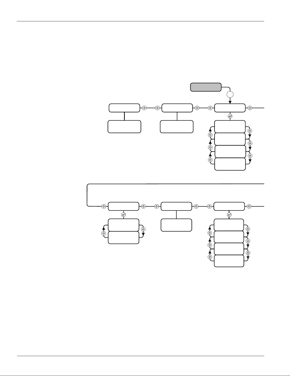
Extended Menus
The Extended Menus are menu items that are used to set up the unit for its HVAC application.
They are also used in servicing the rooftop equipment.
Password
Accessing the Extended Menus requires the operator to enter the four-digit password “4545”,
(see Figure 6) using the keypad buttons located on the controller interface.
Figure 6: Keypad Extended Menu Structure
26 McQuay OM 843-2
Page 29

Extended Menus
One Event
Sched
Beg
End
Optimal Star t
Enable
Space Temp
OA Temp
Htg Rate
Htg OAT
Design Htg OAT
Clg Rate
Clg OAT
Design Clg OAT
Setu p
AI1
Space T Present
Units
BO 9
Manual Control
Supply Fa n
Comp # 1
Comp # 2
Comp # 3
Comp # 4
Cond Fan # 2
Cond Fan # 3
Alarm Ou t
VAV/ Fan Op Out
Heat # 4
Exh Fan # 1
Exh Fan # 2
Sup Fan Spd
Exh Fan Sp d
OA Damper Pos
Manual Control
Heat # 1
Heat # 2
Heat # 3
Alarm Limits
Hi Disch Alm
Lo Disch Alm
Hi Return Alm
Time Settings
Service
Start Up
Recirculate
Zero OA Time
Tnt Override
Post Heat
Password
Notes
1. Your display may not show all of these menus.
Only the menus that apply to this congured unit will
be available.
2. Hit Return to scroll through changeable
variable on the current page .
3. When no alarm is active, hitting Escape when
curser is at page header will return you to the
System page. When any alarm is active, hitting
Escape will return you to the alarm page.
4. Hitting Escape when curser is not at page header
will return you to the top of that page.
Htg Mod VLV
McQuay OM 843-2 27
Page 30

Extended Menus
Condenser Fans
The Condenser Fan menu is used to set up the turning on and off of the condenser fans. The
condenser fans are controlled by the outdoor air temperature. When compressor operation
starts condenser fan #1 always comes on.
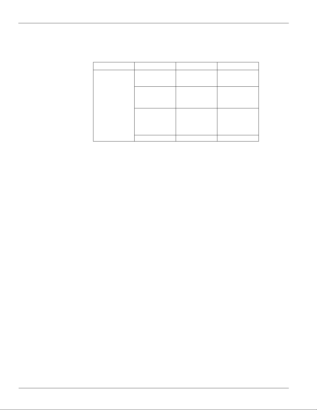
Table 12: System Summary Menus
Menu Menu Item
Cond Fan 2 Spt= 55 50 45 35 0 - 104
Condenser Fan
Cond Fan 3 Spt= 80 80 60 55 0 - 104
Cond Fan 4 Spt= n/a n/a 80 80 0 - 104
030A 035A 040A 050A
Cond Fan 2 Spt= is an adjustable item that turns condenser fan number 2 on when the
outdoor temperature reaches this setpoint.
Cond Fan 3 Spt= is an adjustable item that turns condenser fan number 3 on when the
outdoor temperature reaches this setpoint.
Cond Fan 4 Spt= is an adjustable item that turns condenser fan number 4 on when the
outdoor temperature reaches this setpoint. Not all units have four condenser fans.
Cond Fan Diff= is an adjustable item that sets the temperature differential with respect to the
setpoint.
Default
Range
Economizer
The Economizer menu is used to set up the airside economizer operation.
Table 13: Economizer Menu
Menu Menu Item Default Range
Economizer Pos= - 0 - 100
Disch Air= - -45 - 212
Economizer
(Automatic or CAV)
Economizer Pos= is a status only item that is used to indicate percentage that the economizer
dampers are open.
Disch Air= is a status only item that indicates the current discharge air temperature.
DAT Clg Spt= is an adjustable item which sets the temperature that the DAT should be
maintained at.
Min OA Pos= is a status only item which indicates the current minimum position of the
outdoor air damper (see “Min OA Damper” on page 29).
Chgover Temp= is an adjustable item which sets the OA dry bulb temperature at which the
units changes over to the economizer operation.
Chgover Diff= is an adjustable item which sets the temperature differential with respect to the
Chgover Temp.
DAT Clg Spt= 55.0°F 40.0 - 99.0
Min OA Pos= - 0 - 100
Chgover Temp= 60°F 32.0 - 99.0
Chgover Diff= 2.0°F 1 - 10
28 McQuay OM 843-2
Page 31

Extended Menus
10
20
30
40%
100%
pp
(Minimum)
Min Clg Spd=
(Default 40%)
Demand Control Ventilation
OA Damper Position
Lo Flow Vent Limit=
(Default 30%)
Minimum Outdoor Air
Damper Position
Vent Limit=
(Default 20%)
DCV Limit=
(Default 10%)
OA Damper Position %
Airflow
Min OA Damper
The Min OA Damper menu is used to set up the minimum damper position.
Figure 7 shows a graphical explanation of the control parameters. When a reset scheme is used
(Min OA type=) the OA damper position can be reset, or the damper can be closed to a
position not lower than the Demand Control Ventilation outdoor air damper position profile.
Figure 7: Damper Position vs. Fan Speed Chart
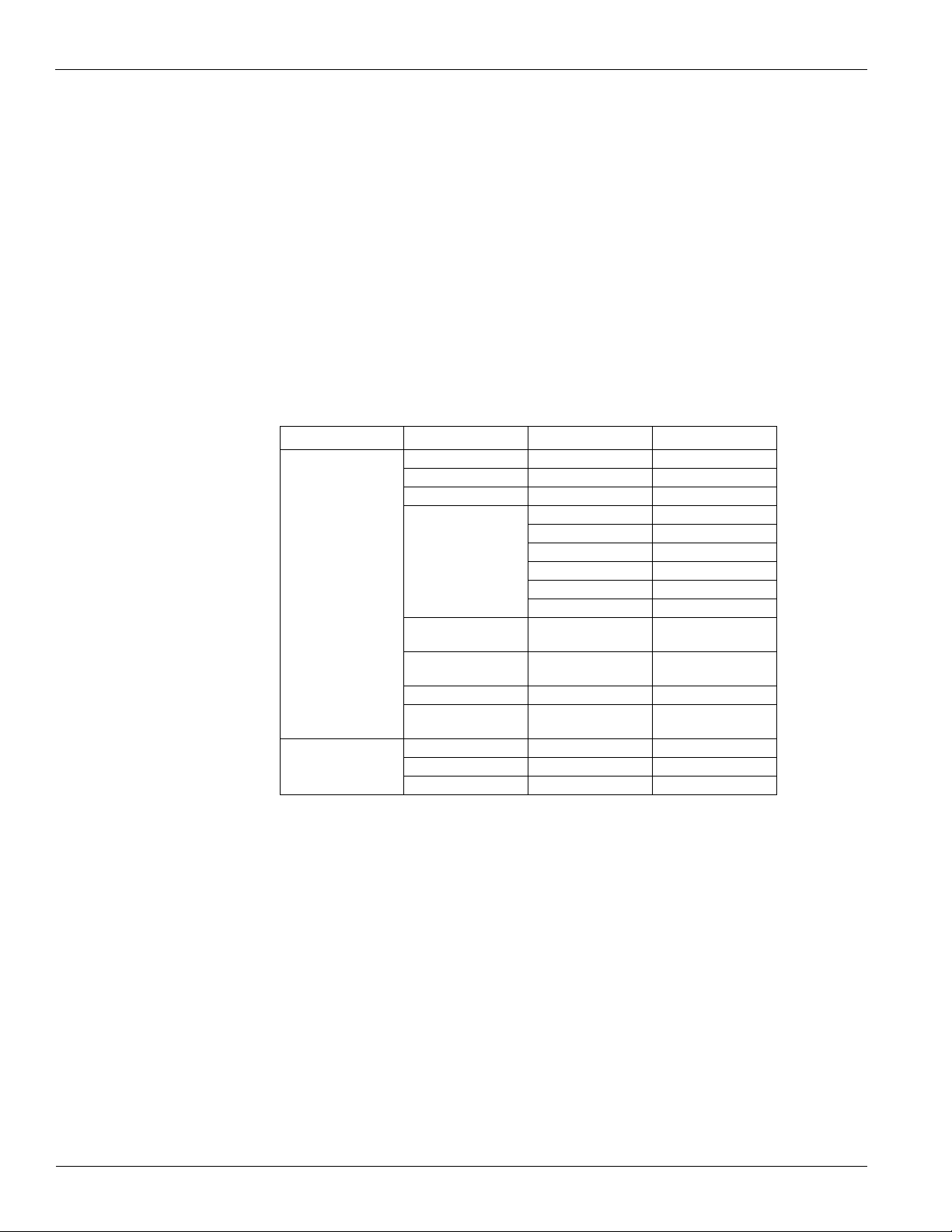
Table 14: Min OA Damper Menu
Menu Menu Item Default Range
Min OA Damper
(w/Econo)
Min OA Damper
(VAV )
Min OA Damper
(no Econo)
Min OA Pos= 0 - 100
Vent Limit= 20% 0 - 99
DCV Limit= 0% 0 - 99
None
Min OA Type= None
% @ DCV Limit= 0 0 - 99.9
% @ Vent Limit= 99.9 0 - 99.9
PPM @ DCV Limit= 800 0 - 9999
PPM @ Vent Limit= 1000 0 - 9999
IAQ PPM=
PPM @ 04 mA 0 - 20 mA/V
PPM @ 20 mA 0 - 20 mA/V
Ext Percent=
0% @ 0 V 0 - 20 mA/V
100% @ 10 V 0 - 20 mA/V
Min Clg Spd= 40% 0 - 99
LoFlo Vent Limit= 30% 0 - 99
Min OA Pos=
Min OA Spt= 20% 1 - 100
Network
External
IAQ
McQuay OM 843-2 29
Page 32

Extended Menus
Min OA Pos= is a status only item which indicates the current minimum position of the
outdoor damper. This value does not go above a value called the Ventilation Limit and does
not go below a value called the Demand Control Ventilation Limit.
On CAV units the Ventilation Limit and the Demand Control Ventilation Limit are fixed
values set equal to the Vent Limit= and DCV Limit= parameters.
On VAV units the OA Damper Position increases from the Vent Limit= value to the LoFloVent
Limit= value as the VFD speed goes from 100% down to the Min Clg Spd= value. The
Demand Control Ventilation Limit in this is determined by the Ventilation Limit X DVC
Limit=/Vent Limit=.
When the Min OA Type= parameter is set to “None” the Min OA Pos= value is set to the
Ventilation Limit. If Min OA Type= is set to Network, External or IAQ, the Min OA Pos=
varies between the Ventilation Limit and the Demand Control Ventilation Limit as the reset
signal varies from its maximum to minimum value.
Vent L imit = is an adjustable item that sets the value of the Ventilation Limit on a CAV unit or
when a VAV unit is at 100% discharge fan speed.
DCV Limit= is an adjustable item that sets the value of the Demand Control Ventilation Limit
on a CAV unit or when a VAV unit is at 100% discharge fan speed. This item is only used
when the “Min OA type=” is set to something other than “None”.
Min OA Type= is an adjustable item that sets the type of minimum OA damper position reset
to be used. When this is set to “None” the Min OA Pos= parameter is set to the Ventilation
Limit and the Demand Control Ventilation Limit parameter is ignored. When this is set to
“Network”, “External”, or “IAQ”, then the Min OA Pos= parameter varies from the
Ventilation Limit down to the Demand Control Ventilation Limit as the reset signal goes from
its maximum to minimum value.
Examples of typical Min OA reset schedules:
If IAQ is selected as the Min OA Type, the Minimum OA Position is calculated based on a
0-10V CO2 sensor input. The CO2 level is expressed as PPM (Parts per Million). The
minimum and maximum sensor input values (0-10V) and the corresponding minimum and
maximum PPM values are user changeable. This calculated Minimum OA Position varies
linearly from the Demand Control Ventilation Limit at the value labeled “PPM @ DCV
Limit” to the Ventilation Limit at the value labeled “PPM @ VentLimit”. The “PPM @
DCV Limit” is not allow to be set equal to or greater than the “PPM @ VentLimit”.
Example #1 Min OA reset type = IAQ VDC
If the requirement is to have the OA damper be at its minimum (DCV Limit) when the
CO2 levels are less than 800PPM and to be at its maximum (Vent Limit) when the CO2
levels are greater than 1000PPM, the controller would be set up as follow:
Vent Limit = 100%
DCV Limit = 0%
Min OA reset type = IAQ
PPM@DCV Limit = 800
PPM@Vent Limit = 1000
IAQ PPM = Current PPM
0 PPM @ 0 V
2000 PPM @ 10 V
Min Clg Spd = 30%
LoFlo Vent Limit = 100%
In this example the Minimum OA Position would vary linearly from 0% outside air at
800PPM or less to 100% outside air at 1000PPM or greater.
30 McQuay OM 843-2
Page 33

Extended Menus
Examples of typical Min OA reset schedules:
If External is selected as the Min OA Type, the Minimum OA Position is calculated based
on an external DC voltage or mA signal.. This calculated Minimum OA Position varies
linearly from zero % the changeable minimum external signal to 100%at the changeable
maximum external signal, but it is set no lower than the Demand Control Ventilation Limit
and no higher than the Ventilation Limit.
Example #2 Min OA reset type = EXT VDC
If the requirement is to have the OA damper be at its minimum (DCV Limit) when the
field supplied signal is at its minimum (0VDC) and to be at its maximum (Vent Limit)
when the field supplied signal is at its maximum (10VDC), the controller would be set up
as follow:
Vent Limit = 100%
DCV Limit = 0%
Min OA reset type = External
0% @ DCV Limit
100% @ Vent Limit
0% @ 0 V
100% @ 10 V
Min Clg Spd = 30%
LoFlo Vent Limit = 100%
In this example the Minimum OA Position would vary linearly from 0% outside air at 0
VDC to 100% outside air at 10 VDC.
XXX % @ DCV Limit= is an adjustable item used when Min OA Type= is set to “External”
to define at what percent of the field input signal the Min OA Pos= is to be at the Demand
Control Ventilation Limit value.
XXX % @ Vent Limit= is an adjustable item used when Min OA Type= is set to “External”
to define at what percent of the field input signal the Min OA Pos= is to be at the Ventilation
Limit value.
Ext Percent= is a status only item that indicates what percent the field signal currently is
between the minimum and maximum value when Min OA Type= is set to “External”.
0 % @ XX V/mA= is an adjustable item that sets the minimum DC voltage or mA value of
the field signal used when Min OA Type= is set to “External”.
100 % @ XX V/mA= is an adjustable item that sets the maximum DC voltage or mA value of
the field signal used when Min OA Type= is set to “External”.
XXXX PPM @ DCV Limit= is an adjustable item used when Min OA Type= is set to “IAQ”
to define at what PPM value the Min OA Pos= is to be at the Demand Control Ventilation
Limit value.
XXXX PPM @ Vent Limit= is an adjustable item used when Min OA Type= is set to “IAQ”
to define at what PPM value the Min OA Pos= is to be at the Ventilation Limit value.
IAQ PPM= is a status only item which indicates the current reading from the CO
sensor.
2
XXXX PPM @ XX V/mA= is an adjustable item that sets the minimum PPM value and the
minimum DC voltage or mA value of the CO
sensor used when Min OA Type= is set to
2
“IAQ”.
XXXX PPM @ XX V/mA= is an adjustable item that sets the maximum PPM value and the
maximum DC voltage or mA value of the CO
sensor used when Min OA Type= is set to
2
“IAQ”.
Min Clg Spd= is an adjustable item that sets the discharge fan speed on a VAV unit at which
the Ventilation Limit reaches the LoFloVent= value.
McQuay OM 843-2 31
Page 34

Extended Menus
LoFlo Vent Limit= is an adjustable item that sets the maximum value for the Ventilation
Limit on a VAV unit.
Daily Schedule
The Daily Schedule sets the start and stop times for each of the days of the week. One start and
one stop time can be set for each day.
Table 15: Daily Schedule Menu
Menu Menu Item Default Range
Mon= 00:00 - 00:00 00:00 - 23:59
Tue= 00:00 - 00:00 00:00 - 23:59
Wed= 00:00 - 00:00 00:00 - 23:59
Daily Schedule
Thu= 00:00 - 00:00 00:00 - 23:59
Fri= 00:00 - 00:00 00:00 - 23:59
Sat= 00:00 - 00:00 00:00 - 23:59
Sun= 00:00 - 00:00 00:00 - 23:59
Hol= 00:00 - 00:00 00:00 - 23:59
Holiday Schedule
The Holiday Schedule is used to set the start and stop times for up to 16 different holidays.
Table 16: Holiday Schedule Menu
Menu Menu Item Default Range
Hol 1= NA 00 - NA 00 Jan-Dec 0-31
Hol 2= NA 00 - NA 00 Jan-Dec 0-31
Hol 3= NA 00 - NA 00 Jan-Dec 0-31
Hol 4= NA 00 - NA 00 Jan-Dec 0-31
Hol 5= NA 00 - NA 00 Jan-Dec 0-31
Hol 6= NA 00 - NA 00 Jan-Dec 0-31
Hol 7= NA 00 - NA 00 Jan-Dec 0-31
Holiday Schedule
Hol 8= NA 00 - NA 00 Jan-Dec 0-31
Hol 9= NA 00 - N A00 Jan-Dec 0-31
Hol 10= NA 00 - NA 00 Jan-Dec 0-31
Hol 11= NA 00 - NA 00 Jan-Dec 0-31
Hol 12= NA 00 - NA 00 Jan-Dec 0-31
Hol 13= NA 00 - NA 00 Jan-Dec 0-31
Hol 14= NA 00 - NA 00 Jan-Dec 0-31
Hol 15= NA 00 - NA 00 Jan-Dec 0-31
Hol 16= NA 00 - NA 00 Jan-Dec 0-31
To enter a 1-day holiday, the start date and the end date must both be entered as the same day.
For example: To enter a holiday of July 4th, the date must be entered as “Jul 04 - Jul 04”. If
both the start and end dates are not entered, the unit will not recognize the holiday.
The start and stop times for the holidays must be entered at the daily schedule menu
(Table 16). All 16 holidays will follow the start and stop times as indicated in the daily
schedule for “hol=”.
32 McQuay OM 843-2
Page 35

Extended Menus
One Event Sched
The One Event Schedule is used to set the start and stop times for one event.
Table 17: One Event Sched Menu
Menu Menu Item Default Range
One Event Sched
Optimal Start
The Optimal Start menu is used to set up the unit so it starts at the most efficient time before
building occupancy.
Table 18: Optimal Start Menu
Menu Menu Item Default Range
Optimal Start
Beg= NA 00 @ 00:00 Jan-Dec 00:00-23:59
End= NA 00 @ 00:00 Jan-Dec 00:00-23:59
Enable= No No/Yes
Space Temp= - -45 - 212
OA Temp= - -45 - 212
Htg Rate= .400 .000 - .999
Htg OAT= 35°F -40 - 60
Design Htg OAT= 0°F -40 - 60
Clg Rate= .400 .000 - .999
Clg OAT= 85°F 60 - 140
Design Clg OAT= 95°F 60 - 140
Enable= is an adjustable item that turns on the optimal start feature. Setting the value to yes
will activate this function.
Space Temp= is a status only item that indicates the current space temperature. A space
temperature sensor must be connected to the unit controller for this feature to function. Refer
to “Space Sensor” on page 57.
OA Temp= is a status only item that indicates the current outdoor air temperature.
Htg Rate= is an adjustable item that sets the rate of temperature rise in degrees per minute
when the unit was last started optimally in heating.
Htg OAT= is an adjustable item that sets the outdoor air temperature when the unit was last
started optimally in heating.
Design Htg OAT= is an adjustable item that sets the outdoor air temperature at which the
heating system could just hold the load. Rate of temperature rise would equal zero.
Clg Rate= is an adjustable item that sets the rate of temperature drop in degrees per minute
when the unit last started optimally in cooling.
Clg OAT= is an adjustable item that sets the outdoor air temperature when the unit was last
started optimally in cooling.
Design Clg OAT= is an adjustable item that sets the outdoor air temperature at which the
cooling system could just hold the load. Rate of temperature rise would equal zero.
McQuay OM 843-2 33
Page 36

Extended Menus
Setup
Table 19: Setup Menu
Menu Menu Item Default Range
None
AI1= RAT
Space T Present= Yes
Setup
Units= English
B09= Fan Op Output
AI1= is an adjustable item to indicate what analog input B1 is being used for, a return air
temperature sensor (RAT) or an adjustable space sensor setpoint. If a space sensor is
connected to the unit but it does not have an adjustable setpoint adjustment knob this item
should be set to none. This connection is made at TB2 terminal 108. If a space sensor with
remote setpoint adjustment is used the RAT sensor wiring must be removed.
Space T Present= is an adjustable item to indicate if a space sensor is connected to the unit
controller.
Units= is an adjustable item to indicate if the unit is to display English or Metric units of
measure.
RAT
SpaceSpt
No
Yes
English
Metric
Fan Op
Output
VAV O ut pu t
B09= is an adjustable item to configure binary output B09. This output can be configured for a
fan operation output or a VAV box output.
Time Settings
Table 20: Time Settings Menu
Menu Menu Item Default Range
Service= 0 min 0 - 240
Start Up= 180 sec 0 - 240
Recirculate= 180 sec 120 - 3600
Time Settings
Service= is an adjustable item that sets the amount of time the unit can operate in manual
control.
Startup= is an adjustable item that sets the time in seconds that the unit will perform its
startup operation.
Recirculate= is an adjustable item that sets the time in seconds that the unit operates with only
the fan, recirculating the building air.
Zero OA Time= is an adjustable item that sets the time in minutes that the outdoor air damper
stays at a zero position upon unit start up.
Zero OA Time= 90 min 0 - 240
Tnt Override= 120 min 0 - 300
Post Heat= 0 sec 0 - 180
Password= 15 min 5 - 60
Tnt Override= is an adjustable item that sets the amount of time that the unit will go into
operation when the tenant override button is activated on the space sensor.
Post Heat= is an adjustable item that sets the amount of time in seconds for the post heat
operation.
Password= is an adjustable item that sets the amount of time in minutes that the unit will stay
in the extended menus.
34 McQuay OM 843-2
Page 37

Extended Menus
Time/Date
Table 21: Time/Date Menu
Menu Menu Item Default Range
Time= - 00:00 - 23:59
Time/Date
Time= is an adjustable item that sets the current time.
Date= is an adjustable item that sets the current date.
Day= is an adjustable item that sets the current day of the week.
Stgd Exh Fan Setup
The Stgd Exh Fan Setup is used to setup the operation of the exhaust fans for a CAV
application. This menu is used to select at what OA damper position each of the exhaust fans
will turn on and off.
Table 22: Stgd Exh Fan Setup Menu
Menu Menu Item Default Range
StgdExh Fan Setup
Date= - Jan-Dec 0-31 2000-2009
Day= - Sunday - Saturday
Exh Fan # 1 On= 40% 0 - 99
Exh Fan # 1 Off= 30% 0 - 99
Exh Fan # 2 On= 55% 0 - 99
Exh Fan # 2 Off= 40% 0 - 99
Exh Fan # 3 On= 70% 0 - 99
Exh Fan # 3 Off= 50% 0 - 99
Exh Fan #1 On= is an adjustable item that turns on exhaust fan #1 based on the economizer
position.
Exh Fan #1 Off= is an adjustable item that turns off exhaust fan #1 based on the economizer
damper position.
Exh Fan #2 On= is an adjustable item that turns on exhaust fan #2 based on the economizer
damper position.
Exh Fan #2 Off= is an adjustable item that turn off exhaust fan #2 based on the economizer
damper position.
Exh Fan #3 On= is an adjustable item that turns on exhaust fan #3 based on the economizer
damper position.
Exh Fan #3 Off= is an adjustable item that turn off exhaust fan #3 based on the economizer
damper position.
McQuay OM 843-2 35
Page 38

Extended Menus
Heating Setup
The Heating Setup menu is used to configure the heating operation of the unit.
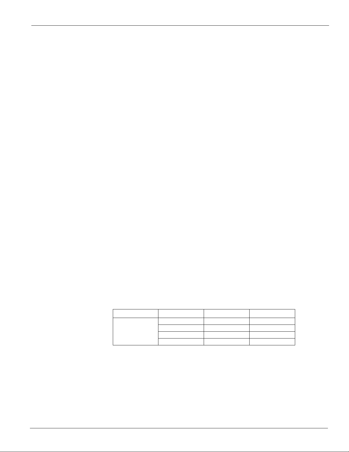
Table 23: Heating Setup Menu
Menu Menu Item Default Range
Unocc Htg Spt= 55.0°F 55.0 - 99.0
Unocc Diff= 3.0°F 1.0 - 9.9
Heating Setup
CtrlTemp Scr= Return
OAT Htg Lock= 60.0°F 1.0 - 99.0
OAT Lock Diff= 3.0°F 1.0 - 9.9
Stage Time= 4 min 4 - 60
Unocc Htg Spt= is an adjustable item that sets the temperature of the space sensor at which
the heating operation will begin when the building is unoccupied. The optional space sensor
must be connected to the unit for this function to operate.
Unocc Diff= is an adjustable item that sets the temperature differential for the setpoint. When
the space temperature goes above the Unocc Htg Spt plus the Unocc Diff, the unit will
transition out of the heating mode of operation.
CtrlTemp Src= is an adjustable item that sets the heating operation control source to either
the space temperature sensor or the return air temperature sensor.
Return
Spac e
OAT Htg Lock= is an adjustable item that sets the maximum outdoor air temperature allowed
for the heating mode of operation to take place.
OAT Lock Diff= is an adjustable item that sets the temperature differential for the OAT Htg
Lock setpoint.
Stage Time= is an adjustable item that sets the timer between each of the heating stages. The
unit will not stage up or down until this time has passed.
36 McQuay OM 843-2
Page 39

Extended Menus
Cooling Setup
The Cooling setup menus is used to configure the cooling operation of the unit.
Table 24: Cooling Setup Menu
Menu Menu Item Default Range
Unocc Clg Spt= 85°F 55.0 - 99.0
Unocc Diff= 3.0°F 1.0 - 9.9
Cooling Setup
CtrlTemp Scr= Return
OAT Clg Lock= 55.0°F 1.0 - 99.0
OAT Lock Diff= 2.0°F 1.0 - 9.9
Stage Time= 4 min 4 - 60
Unocc Clg Spt= is an adjustable item that sets the temperature of the space sensor at which
the cooling operation will begin when the building is unoccupied. The optional space sensor
must be connected to the unit for this function to operate.
Unocc Diff= is an adjustable item that sets the temperature differential for the setpoint. When
the space temperature falls below the Unocc Clg Spt minus the Unocc Diff, the unit will go out
of the cooling mode of operation.
CtrlTemp Src= is an adjustable item that sets the cooling operation control source to either
the space temperature sensor or the return air temperature sensor.
Return
Spac e
OAT Clg Lock= is an adjustable item that sets the minimum outdoor air temperature allowed
for the cooling mode of operation to take place.
OAT Lock Diff= is an adjustable item that sets the temperature differential for the OAT Clg
Lock setpoint.
Stage Time= is an adjustable item that sets the timer between each of the cooling stages. The
unit will not stage up or down until this time has passed.
McQuay OM 843-2 37
Page 40

Extended Menus
Operating Hours
The Operating Hours menu gives a summary of the hours of operation for each of the supply
fan, exhaust fan compressors, heating and economizer operation.
Table 25: Operating Hours Menu
Menu Menu Item Default Range
Supply Fan= 000,000 0 - 999,999
Exhaust Fan= 000,000 0 - 999,999
Mech Cool= 000,000 0 - 999,999
Comp # 1= 000,000 0 - 999,999
Operating Hours
Supply Fan= is a status item which gives the number of hours the supply fan has operated.
Exhaust Fan= is a status item which gives the number of hours the exhaust fans have
operated.
Mech Cool= is a status item which gives the number of hours that mechanical cooling has
operated.
Comp #1= is a status item which gives the number of hours that compressor #1 has operated.
Comp #2= is a status item which gives the number of hours that compressor #2 has operated.
Comp # 2= 000,000 0 - 999,999
Comp # 3= 000,000 0 - 999,999
Comp # 4= 000,000 0 - 999,999
Heating= 000,000 0 - 999,999
Economizer= 000,000 0 - 999,999
Tnt Override= 000,000 0 - 999,999
Comp #3= is a status item which gives the number of hours that compressor #3 has operated.
Comp #4= is a status item which give the number of hours that compressor #4 has operated
Heating= is a status item which gives the number of hours that the heating mode has operated.
Economizer= is a status item which gives the number of hours that the economizer has
operated.
Tnt Override= is a status item which gives the number of hours that the unit has operated in
the Tenant Override mode of operation.
38 McQuay OM 843-2
Page 41

Extended Menus
Manual Control
The manual control of operation is a function that is used for operating the unit during a
service call only. The unit must not be operated in this mode for any extended period of time.
WARNING
Unit damage may occur when operating in manual control mode. Run in
this condition by an experienced technician only.
WARNING
Operating the unit in manual control can cause personal injury or
equipment damage.
Manual control operation must only be performed by personnel that are
knowledgeable in the operation of the equipment.
Table 26: Manual Control Menu
Menu Menu Item Default Range
On
Off
On
Off
On
Off
On
Off
On
Off
On
Off
On
Off
On
Off
On
Off
On
Off
On
Off
On
Off
On
Off
On
Off
On
Off
On
Off
On
Off
Manual Control
Manual Ctrl= Off
Supply Fan= Off
Comp # 1= Off
Comp # 2= Off
Comp # 3= Off
Comp # 4= Off
Cond Fan # 2= Off
Cond Fan # 3= Off
Cond Fan # 4= Off
Heat # 1= Off
Heat # 2= Off
Heat # 3= Off
Heat # 4= Off
Exh Fan # 1= Off
Exh Fan # 2= Off
Alarm Out= Off
Vav/Fan Op Out= Off
Sup Fan Spd= 0.0% 0.0 - 100.0
Exh Fan Spd= 0.0% 0.0 - 100.0
OA Damper= 0.0% 0.0 - 100.0
Htg Mod VLV= 0.0% 0.0 - 100.0
Manual Ctrl= is an adjustable item that puts the unit into manual control. Major components
of the unit are turned on and off by this control. The units normal control sequence are
overridden in this state and can cause the unit to go into alarm.
McQuay OM 843-2 39
Page 42

Extended Menus
Supply Fan= is an adjustable item that turns on the supply fan.
Note: Turning on any one of the following compressors will automatically turn on condenser
fan #1. Other condenser fans must be manually turned on to control the head pressure of the
unit. Refrigerant gauges must be connected to the unit for observation of the head pressure in
the manual control mode of operation. Additional condenser fans must be turned on to
maintain the head pressure.
Comp # 1= is an adjustable item that turns on compressor #1.
Comp # 2= is an adjustable item that turns on compressor #2.
Comp # 3= is an adjustable item that turns on compressor #3.
Comp # 4= is an adjustable item that turns on compressor # 4 if unit has one.
Cond Fan # 2= is an adjustable item that turns on the condenser fan #2.
Cond Fan # 3= is an adjustable item that turns on the condenser fan #3.
Cond Fan # 4= is an adjustable item that turns on the condenser fan #4 if unit has one.
Heat # 1= is an adjustable item that turns on the first stage of heat.
Heat # 2= is an adjustable item that turns on the second stage of heat.
Heat # 3= is an adjustable item that turns on the third stage of heat.
Heat # 4= is an adjustable item that turns on the fourth stage of heat.
Exh Fan # 1= is an adjustable item that turns on the first stage of exhaust fans.
Exh Fan # 2= is an adjustable item that turns on the second stage of exhaust fans.
Sup Fan Spd= is an adjustable item only on VAV units that sets the speed of the supply air
fan.
Exh Fan Spd= is an adjustable item for units with building pressure control (VFD on the
exhaust fans) that sets the speed of the exhaust fans.
OA Damper Pos= is an adjustable item that sets the position of the outdoor damper.
Htg Mod VLV= is an adjustable item that allows the valve to be adjusted from its minimum
open position to its full open position.
Note – The unit status will be OFF when the controller is taken out of Manual Control. To start the
unit, change the control mode setting to a non off selection.
Alarm Limits
The Alarm Limits menu is used to set the limits of the discharge air temperature sensor and the
return air temperature sensor.
Table 27: Alarm Limits Menu
Menu Menu Item Default Range
Hi Disch Alm= 170.0°F 90 - 250
Alarm Limits
Hi Disch Alm= is an adjustable item that sets the high temperature limit for the DAT sensor.
When the discharge air temperature sensor reaches this set point the unit will go into the high
discharge air alarm.
Lo Disch Alm= is an adjustable item that sets the low temperature limit for the DAT sensor.
When the discharge air temperature sensor reaches this set point the unit will go into the low
discharge air alarm.
Lo Disch Alm= 40.0°F 20 - 50
Hi Return Alm= 120.0°F 90 - 150
Hi Return Alm= is an adjustable item that sets the high temperature limit for the return air
temperature. When the RAT sensor reaches this set point the unit will go into the high return
air temperature alarm.
40 McQuay OM 843-2
Page 43

Hidden Data Menus
Hidden Data Menus
Hidden information is accessed by pressing the Left and Down buttons at the same time.
Information available on hidden data screens is shown below. The Hidden Menus include the
most advanced items such as “unit configuration” parameters, Network configuration, and
service related parameters. These generally do not needing changing or accessing unless there
is a fundamental change to or a problem with the unit operation.
The following Menu items are meant to be used as a set up and/or troubleshooting tool and
should only be accesses by trained Service Technicians.
Unit Configuration Setup Menu
After the main control board application software is loaded into the MCB, it must be
“configured” for the specific control application. This consists of setting the value of the
configuration variables within the MCB. These variables define things such as the Unit type,
heating type, compressor type, exhaust fan control and the type of outside air damper control.
If all of these items are not set appropriately for the specific unit, the unit will not function
properly. The correct settings for these parameters are defined for a given unit by the unit
“Software Configuration Code”.
Table 28: Unit Configuration Menu
Menu Menu Item Default Range
1=MPS15,
2=MPS15.5
3=MPS20, 4=MPS25
5=MPS30, 6=MPS35
7=MPS40, 8=MPS50
9=MPS60, A=MPS70
B=MPS15A,
C=MPS17.5A
D=MPS17.5B,
E=MPS20B
CAV
VAV
None, 2 Stg, 4 Stg,
LoGas, HiGas,
ModWtr*, ModElec*
Danfoss
Copeland
None
Staged
VFD
No Econ
Econ
Unit Config
Unit Size= 40
Unit Type=
Heat Type = None * Later Versions
Comp Type= Danfoss
Exh Fan Ctrl= None
OA Damper Econo
FixedOADMax= 100% 0-100
AppVersion= 1.07 1.00 - 9.99
ServiceTime= 20sec 0-240
RestoreDefaults? No No/Yes
CAV
McQuay OM 843-2 41
Page 44

Hidden Data Menus
Network Configuration
The MicroTech II Applied Air Handling Unit Controller contains data points or unit variables
that are accessible from three user interfaces: the unit keypad, a BACnet network (BACnet/IP
or MS/TP), or a LONWORKS network. Not all points are accessible from each interface.
Refer to ED 15102-1 (available on www.mcquay.com) for Network Configuration details. ED
15102-1 contains the network details necessary to incorporate the MicroTech II Applied Air
Handling Unit Controller into the network.
Table 29: Network Configuration Menu
Menu Menu Item Default Range
None
LON
BACnet MS/TP
BACnet IP
BACnet Ethernet
Network Config
BAS Comm= None
RcvHrtBt= 30sec 0-3276.4sec
Configure BACnet? No No/Yes
nviSetpoint=
nviDAClSP=
nviOAT=
nviSpaceT=
nviOccCmd=
nviAppMode=
nviEmerg=
nviOAMinPos=
nviSpaceIAQ=
nviDSP Spt=
nviBSP=
nviBSP Spt=
nviSupFanCap=
nviExhFanCap=
nviCurrSched=
nviNextSched=
nviTimeToNext=
nviCoolState=
nviCoolValue=
nviHeatState=
nviHeatValue=
nviEconoState=
nviClrAllAlms=
nviClrOneAlm=
nciOccCoolSpt=
nciOccHeatSpt=
nciDAClSP=
nciDAClSP=
Temp C OV=
42 McQuay OM 843-2
Page 45

Hidden Data Menus
Economizer Control
The control algorithm is a PI loop with the Integral gain adjusted based on OAT to provide
accurate control over a wide range of outdoor air temperatures. Testing was conducted to
determine operating parameters so no field adjustment should be required.
Table 30: Economizer Control Menu
Menu Menu Item Default Range
Sample Time= 60sec 0-999
Econ Zone Loop
Econ DAT Loop
Duct Static Pressure Control
The control loop used to modulate the fan speed to maintain a measured duct static pressure at
a setpoint is based on the fan laws. For a given system, duct static pressure varies with the
square of the speed according to the fan laws.
Note – IMPORTANT: The sample time must be long enough to allow the static pressure to get
very close to its steady state value before another calculation is made. The VFD ramp
time value on the keypad must be changed whenever the ramp time of the VFD is
changed. The ramp up time must equal the ramp down time to provide stable operation.
PA Time= 600sec 0-999
Gain= 100 0-999
Sample Time= 30sec 0-999
PA Time= 60sec 0-999
Gain= 10 0-999
Actuator Time= 60sec 0-999
Econ= 0% @ V 2 0-9.9
Econ= 100% @ V 10 0-99.9
Table 31: Alarm Limits Menu
Menu Menu Item Default Range
MinSampleTime= 5sec 0-99
VFD Ramp Time= 60sec 0-999
Max VFD Chg= 15.00% 0-99.9
MinSupFanSpd= 25% 0-99.9
Duct Press Loop
Speed= 0% @ V 0 0.0-9.9
Speed=100% @ V 10 0.0-99.9
DSP= 0 @ mA 4 0.0-9.9
DSP= 5 @ mA 20 0.0-99.9
DSP CtrlDelay= 30sec 0-999
McQuay OM 843-2 43
Page 46

Hidden Data Menus
Building Static Pressure Control
The modulated exhaust fans are turned on if the outside air dampers are controlled to at least
their minimum position and the building static pressure is above the building static pressure
setpoint by more than the deadband for longer than the Minimum Exhaust Fan Start Time
(Default = 120 seconds).
The modulated exhaust fans are turned off when the supply fan is turned off. They are also
turned off if the building static pressure is below the building static pressure setpoint by more
than half the deadband and the Exhaust Fan capacity is at its minimum value (Default = 25%)
for longer than the Min Exhaust Fan Stop Time (Default = 120 seconds).
A PI control loop is used to modulate the variable frequency drive of the exhaust fans to
maintain a measured building static pressure at a setpoint.
Table 32: Building Pressure Loop Menu
Menu Menu Item Default Range
Sample Time= 5sec 0-99sec
PA Time= 0sec 0-999sec
Gain= 50 0-999
MinExhFanSpd= 25.00% 0-99.9%
Speed= 0% @ V 0 0.0-9.9
Speed=100% @ V 10 0.0-99.9
Bldg Press Loop
ExhFanActTime= 120sec 0-999
ExhStartTime= 120sec 0-999
ExhStopTime= 120sec 0-999
BSP=-.250IWC@
mA
BSP=+.250IWC@
mA
4 0.0-9.9
200 0.0-99.9
Project Ahead Time - Zone Control
In Zone Control cooling and heating operation, the Projected Control Temperature reduces
overshoot as the zone temperature approaches a setpoint after startup. It does this by causing
stages to stop increasing before the actual Control Temperature reaches the setpoint.
Table 33: Zone Control Menu
Menu Menu Item Default Range
Zone ControlPA PA Time= 700sec 0-9999
Time Settings
The Supply Fan is turned On when the unit enters the Recirculation state. The Supply Fan is
turned off when the unit transitions to the off state, but it stays on for a OffHtClDelayTime
(Default- 120 seconds) after compressors shut down or heat is turned off.
Table 34: Time Settings Menu
Menu Menu Item Default Range
Time SettingsOff HtClDelay= 120sec 0-999
44 McQuay OM 843-2
Page 47

Hidden Data Menus
Operating Hours Config Menu
The current run times shown in the Op Hours Config Menu can be changed via the keypad.
This may be used to set the value for a component to zero if it is replaced for example. The
values in temporary memory are written to permanent memory at the Write Interval (Default
period = 8 Hours) this value is editable in the first screen of the Op Hours Config menu. In the
event of a power loss, the temporary values start from the permanent values so the number of
operating hours that are lost would be between 0 and the Write Interval.
Table 35: Operating Hours Configuration Menu
Menu Menu Item Default Range
Write Interval= 8Hrs 0-99
Sec/Hr Adjust= 3600 0-9999
Supply Fan=
Exhaust Fan=
Mech Cool=
Op Hours Config
Comp # 1 =
Comp # 2 =
Comp # 3 =
Comp # 4 =
Heating=
Economizer=
Tnt Override=
Remote Alarm Output Configuration
The action of this output depends on the setup of each of the possible alarms. The output is on
continuously (field relay energized) when there are no active alarms within the unit controller.
Each alarm is then configured to cause the output to turn off, blink on and off rapidly, blink on
and off slowly, or remain on (no alarm indication).
Table 36: Alarm Out Menu
Menu Menu Item Default Range
Off
Emergency Off= Fast
Control T Fail= Fast Same as Above
Alarm Out Faults
Alarm Out Problems
Alarm Out Warning Dirty Filter = Off Same as Above
Disch Sensor= Fast Same as Above
Duct Hi Limit= Fast Same as Above
Hi Return Tmp= Fast Same as Above
Hi Disch Tmp= Fast Same as Above
Lo Disch Tmp= Fast Same as Above
Fan Fault= Fast Same as Above
OAT Sensor= Slow Same as Above
Space Sensor= Slow Same as Above
Return Sensor= Slow Same as Above
Hi Pres-Ckt1= Slow Same as Above
Hi Pres-Ckt2= Slow Same as Above
Lo Pres-Ckt1= Slow Same as Above
Lo Pres-Ckt2= Slow Same as Above
Slow
Fast
On
McQuay OM 843-2 45
Page 48

Hidden Data Menus
Alarm Delays
The Alarm Delays Setup Menu can be accessed when a password has been entered. The
default settings are the result of many years of testing and should not be changed. The Alarm
Delay Setup Menu should only be accessed by trained service personnel.
Table 37: Alarm Delays Menu
Menu Menu Item Default Range
Airflow= 120sec 0-999
Pressure= 10sec 0-999
Low Pressure= 60sec 0-999
Temperature= 30sec 0-999
Alarm Delays
High Temp= 30sec 0-999
Low Temp= 180sec 0-999
Heat= 15sec 0-999
Power Up= 5sec 0-999
Alarm Output= 1sec 0-999
46 McQuay OM 843-2
Page 49

Controller
Controller
This section of the manual describes the MicroTech II Controller components, input/output
configurations, field wiring options and requirements, and service procedures.
NOTICE
This equipment generates, uses, and can radiate radio frequency energy. If not
installed and used in accordance with this instruction manual, it can interfere
with radio communications. It has been tested and found to comply with the
limits for a Class A digital device, pursuant to part 15 of the FCC rules. These
limits are designed to provide reasonable protection against harmful
interference when the equipment is operated in a commercial environment.
Operation of this equipment in a residential area is likely to cause harmful
interference; in which case users will be required to correct the interference at
their own expense.
McQuay International disclaims any liability resulting from any interference or for
the correction thereof.
WARNING
Electric shock hazard. Can cause personal injury or equipment damage.
This equipment must be properly grounded. Connections and service to the
MicroTech II control panel must be performed only by personnel knowledgeable
in the operation of the equipment being controlled.
WARNING
Excessive moisture in the control panel can cause hazardous working
conditions and improper equipment operation.
Protect the electrical components in the main control panel from precipitation.
CAUTION
Extreme temperature can damage system components.
This MicroTech II controller is designed to operate in ambient temperatures
from –40°F to 158°F. It can be stored in ambient temperatures from –65°F to
176°F. The controller is designed to operate in a 10% to 90% RH
(noncondensing) and be stored in a 5% to 95% RH (noncondensing)
environment.
CAUTION
Static sensitive components. A static discharge while handling electronic circuit
boards can damage components.
Discharge any static electrical charge by touching the bare metal inside the
main control panel before performing any service work. Never unplug any
cables, circuit board terminal blocks, relay modules, or power plugs while power
is applied to the panel.
CAUTION
To prevent possible unit damage, before removing power to the controller, pump
down compressor.
McQuay OM 843-2 47
Page 50

Controller
General Description
The MicroTech II Controller for Maverick Commercial Packaged Units is microprocessorbased and designed to provide sophisticated control of McQuay Maverick rooftop units. In
addition to providing normal temperature, static pressure, and ventilation control, the
controller can provide alarm monitoring and alarm-specific component shutdown if critical
system conditions occur.
The operator can access temperatures, pressures, operating states, alarm messages, control
parameters, and schedules with a 6-key keypad and a 4-line by 20-character display. The
controller includes password protection against unauthorized or accidental control parameter
changes.
This MicroTech II controller is capable of complete, stand-alone rooftop unit control, or it can
be incorporated into a building-wide network using an optional plug-in communication
module. Available communication modules include BACnet
Ethernet, L
Controller (DAC).
ONMARK
®
Space Comfort Controller (SCC) and LONMARK Discharge Air
®
/IP, BACnet MS/TP, BACnet
Control Panel
The unit control panel’s main component is the controller as indicated in Figure 8. The
controller along with the ancillary components of contactors, switches, motor protectors, and
miscellaneous control items make up the complete unit control panel.
48 McQuay OM 843-2
Page 51

Figure 8: Control Panel Layout and Description
ID
AC T3
AH L
CB10
CB51
CCH1 - 4
DAT
DHL
DS 1
F1A, B
F1C
HL
HP1, 2
LP1, 2
M1 - 4
M10
M11 - 13
M51, 52
MCB
MJ
MMP1 - 4
MMP10
MMP11 - 13
MMP51
OAE
OAT
PB1
PC5
PC7
R _HP1, 2
R _HTR 1, 2
R _FANOP
R _VFD10
R _VFD51
RAE
RAT
REC1
SPS1
SPS2
T1
T2
TB1
TB2
TB51
VFD10
VFD51
Te rminal Block, Exhaust Fan Distribution
Variable Frequency Drive, Supply Fan
Variable Frequency Drive, Exhaust Fans
Receptical, GFCI
Static Pressure Sensors, Duct
Static Pressure Sensors, Building
Tr ans former, Main Control (Line/115VAC)
Tr ans former, Control Input (115/24VAC)
Te rminal Block, Internal Distribution
Te rminal Block, Field
Relay, VFD Enable, Suppl y Fa n
Relay, VFD Enable, Exhaust Fans
Enthalpy Sensor, Return Air
Te mperature Sensor, Return Air
Pressure Control, Proof Airf low Switch
Relay, High Pressure Switch, Circuits 1 & 2
Relay, Heater stages 1 & 2
Relay, Fan Operatio n
Enthalpy Sensor, Outside Air
Te mperature Sensor, Outside Air
Power Block, Power Distribution
Pressure Control, Dirty Filter Switch
Manual Motor Protector, Compressors
Manual Motor Protector, Supply Fan
Manual Motor Protector, Condenser Fans
Motor Protector, Exhaust Fan(s)
Contactor, Condenser Fans
Contactor, Exhaust Fans
Microprocessor Circuit Board
Mechanical Jumper
Hi-Pressure Switch, Refrigeration Circuits 1, 2
Low-Pressure Switch, Re frigeration Circuits 1, 2
Contactor, Compressors
Contactor, Supply Fan
Disconnect Switch
Fuse, Control Circuit Trans former (T 1), Primary
Fuse, Control Circuit Trans former (T 1), Secondary
Hi-Lim it Switch, Gas Heat
Circuit Breaker, Exhaust Fan(s)
Crank case Heater
Te mperature Sensor, Discharge Ai r
Duct Hi-Limit, Switch
Description
Actuator Motor, Economizer
Auxiliary Hi-Limit Swit ch, Gas Heat, Manual Rese t
Circuit Breaker, Supply F an
TB1
R
_
H
P
1
R
_
H
T
R
1
R
_
V
F
D
1
0
R
_
F
A
N
O
P
T2
T1
PC5
PC7
DHL
REC1
VFD10
M4 MMP 4
M2
M1
M3
MMP2
MMP1
MMP3
M11 MMP11
M12 MMP13
M13
MMP10
CB10
M10
PB1
TB 51
TB2
MCB
R
_
H
P
2
R
_
H
T
R
2
R
_
V
F
D
5
1
F1 C/B/A
VFD51
MMP51
CB51
M51 M52
DS1
SPS1
SPS2
Field Terminals
Factory Wiring
Field Wiring
Factory Terminals
Plug Connector
200/ H200
Wire /Harness Number
Shielded Wire/ Cable
Optional Component
ID
Description
Controller
McQuay OM 843-2 49
Page 52

Controller
Rx-/Tx-
Rx+/Tx+
GN
D
C1
NO1
NO2
NO3
C1
C4
NO4
NO5
NO6
C4
C7
NO7
C7
NO8
C8
NC8
NO12
C12
NC12
NO1
3
C13
NC1
3
C9
NO9
NO10
NO1
1
C9
G
G0
B1
B2
B3
GND
+VDC
+V
term
GN
D
+5V
RE
F
B4
BC4
B5
BC5
VG
VG0
Y1
Y2
Y3
Y4
ID1
ID2
ID
3
ID4
ID5
ID6
ID7
ID
8
IDC1
B6
B7
B8
GN
D
ID9
ID
10
ID11
ID
12
IDC9
ID13
H
ID13
IDC13
ID14
ID
14
H
NO1
4
C14
NC14
NO15
C15
NC1
5
C16
NO1
6
NO17
NO18
C1
6
E-
E+
GND
ID
15
H
ID
15
IDC15
ID
16
ID
16
H
Y5
Y6
ID
17
ID
18
IDC1
7
B9
BC9
B1
0
BC1
0
J1
J24
J2
J3
eld card serial card
J4 J5
J6
J19
J7
J8
J20
service card
J9 J10
J11
J21
J12
J13 J14
J15
J16
J22
J23
J17
J18
Unit Controller
The unit controller is made up of the integral keypad with LED display, digital inputs, digital
outputs, analog inputs, and analog outputs. The MPS equipment has either a large or a medium
unit controller depending if the rooftop unit has gas heat and a VAV application or not. The
difference between a large and a small unit controller is the number of inputs and outputs it
has. See Figure 9 for details on the unit controller.
Figure 9: Unit Controller
Analog Input
The unit controller receives up to 8 analog inputs. The sensors are described as follows:
Table 38: Analog Input
Controller Input Description Value
B1 RAT/Space setpoint RTD
B2 Space temperature RTD
B3 CO2/Ext. minimum position Volts/mA
B4 Discharge air temperature RTD
B5 Outdoor air temperature RTD
B6 Duct static pressure 4-20 mA
B7 Building static pressure 4-20 mA
B8 DAT setpoint reset Volts/mA
50 McQuay OM 843-2
Page 53

Controller
Analog Output
The unit controller receives up to 4analog outputs. The sensors are described as follows:
Table 39: Analog Output
Controller Output Description Value
Y1 Economizer actuator 0-10 VDC
Y2 Supply fan VFD 0-10 VDC
Y3 Exhaust fan VFD 0-10 VDC
Y4 Modulating heating actuator 0-10 VDC
Binary Inputs
The unit controller receives up to 9 binary inputs. The device description is as follows:
Table 40: Binary Input
Controller Input Description 24 V Present Indication
ID1 Remote start/stop Enabled
ID2 Emergency stop Operational
ID3 Airflow switch Airflow detected
ID4 Enthalpy switch Low OA ambient
ID5 Filter switch Normal
ID6 High pressure/Low pressure 1 Normal
ID7 High pressure switch Alarm
ID8 High pressure/Low pressure 2 Normal
ID9 Duct high limit Normal
Fan Control
The supply air fan is controlled by the NO1 output. This output is wired in with the fan
interlock and relay R_VFD10 for VAV units and relay M10 for CAV applications.
The exhaust fans are controlled by the NO3 output for building pressure control applications.
This output is wired to relay R_VFD51. For CAV applications with staged control the exhaust
fans are controlled by outputs NO3 and NO10. These outputs are wired to relays M51 and
M52 respectively.
Table 41: Binary Output
Controller Output Description Energized Indication
NO1 Supply fan start/stop On
NO2 Condenser fan #2 On
NO3 Exhaust fan #1 On
NO4 Heat stage 1 On
NO5 Heat stage 2 On
NO6 Compressor #1, circuit 1 On
NO7 Compressor #2, circuit 2 On
McQuay OM 843-2 51
Page 54

Controller
Table 41: Binary Output
Controller Output Description Energized Indication
NO8 Alarm On
NO9 VAV/Fan operation output On
NO10 Exhaust fan #2 and #3 On
NO11 Condenser fan #3 On
NO12 Compressor #2 and #3, circuit 1 On
NO13 Compressor #2 and #3, circuit 2 On
NO14 Condenser fan #4 On
NO15 N/A N/A
NO16 Heat stage 3 On
NO17 Heat stage 4 On
NO18 N/A N/A
52 McQuay OM 843-2
Page 55

Controller
Power Supply Terminals
Transformer T2 supplies 24 V (ac) power to the unit controller and connects at terminal G and
GO. The analog input power supply is also supplied by T2 and is connected at VG and VGO.
Communication Modules
In systems that require networking, one of the following communication modules can be
installed on the unit controller:
• BACnet/IP or BACnet Ethernet
• BACnet MS/TP
• LonWorks, Space Comfort Control (SCC)
• LonWorks, Discharge Air Control (DAC)
BACnet/IP or BACnet Ethernet
The BACnet/IP or BACnet Ethernet communication module is designed to be an add on
module to the unit controller. The MicroTech II unit controller meets the requirements of
ANSI/ASHRAE 135-2001 standard.
BACnet MS/TP
The BACnet MS/TP communication module is designed to be an add-on module to the unit
controller. The MicroTech II unit controller meets the requirements of ANSI/ASHRAE 1352001 standard for BACnet Master Slave/Token Passing protocol.
LonWorks SCC
The LonWorks communication module is designed to be an add-on module to the unit
controller. The SCC module supports the LonMark Space Comfort Controller functional
number 8504.
LonWorks DAC
The LonWorks communication module is designed to be an add-on module to the unit
controller. The DAC module supports the LonMark Discharge Air Controller functional
number 8610.
The installation of each of the above communication modules is further explained in each of
the respective Engineering and Data (ED) documents.
Keypad/Display
The keypad display shown in Figure 1 is the operator interface to the unit controller. The
keypad has 6 function keys that provide the navigation. The display is a 4 line display with
each line made up of 20 characters. All operating conditions, system alarms, control
parameters, and schedules can be monitored from the keypad/display.
McQuay OM 843-2 53
Page 56

Controller
Temperature Sensors
The MicroTech II controller uses passive negative temperature coefficient (NTC) thermistors.
These sensors vary their input resistance to the controller as the temperature changes.
Table 42: Temperature/Resistance
Temperature °F Resistance in Ohms
-40 336,050
-31 242,397
-22 176,785
-13 130,295
-4 96,999
5 72,906
14 55,301
23 42,315
32 32,650
41 25,394
50 19,903
59 15,714
68 12,493
77 10,000
86 8056
95 6530
104 5325
113 4367
122 3601
131 2985
140 2487
149 2082
158 1752
167 1480
176 1256
185 1070
194 915.9
203 786.8
212 678.4
221 587.1
230 509.8
239 444.2
248 388.3
54 McQuay OM 843-2
Page 57

Table 43: Resistance vs. Temperature for Setpoint Adjustment
Stat ic Pressur e ( “W.C.)
Sensor Ou tput (mA)
05
4
20
Stat ic Pressur e ( “W.C.)
Sens or Output (mA)
-.25
+.25
4
20
Duct Pressur e
Buildin g Pressure
Ohms T (°F) T (°C)
5000 50 10
6000 54 12
7000 57 14
8000 61 16
9000 64 18
10,000 68 20
11,000 72 22
12,000 75 24
13,000 79 26
14,000 82 28
15,000 86 30
Controller
Pressure Transducers
The MicroTech II controller uses 0 to 5" wc, 4-20 mA static pressure transducers for
measuring duct static pressure. If building static pressure control is provided, a –0.25" wc to
0.25" wc, 4-20 mA static pressure transducer is used.
Figure 10: Sensor Output
Actuators
The actuators are controlled by an analog signal from the unit controller.
Spring-return actuators are used for the 0 - 30% outdoor air and economizer dampers. The
mixing dampers are normally closed to the outside air.
McQuay OM 843-2 55
Variable Frequency Drives (VFDs)
When controlling the supply air fan or the exhaust fans with a variable frequency drive, the
MicroTech II controller uses an analog output signals to modulate the drive speed.
Page 58

Field Wiring
Field Wiring
Field Output Signal
The following output signals may be available for field connections to a suitable device.
• Remote Alarm Output
• Fan Interlock
• VAV Box O u t p u t
The Remote Alarm Output and Fan Operation Output are available on all units. The VAV Box
Output is available only on VAV units.
Remote Alarm Output
The remote alarm output, dry contact NO8, closes when the unit controller has an active
alarm. To use this signal wire a field supplied 24 V (ac) relay/contact across terminals 120 and
122 on TB2. This and additional wiring information can be seen on the output wiring
schematics at line number 334.
Fan Interlock
The output terminal on the unit controller, NO1, is energized when the supply fan is on. This
output is wired to TB2 at terminals 118 and 119. All units should have a mechanical jumper
(MJ118) installed at these terminals. This output supplies 115 V (ac) to these terminals. A fan
interlock switch can be installed at this location to control the start of the fan. This and
additional wiring information can be seen on the output wiring schematics at line number 303.
VAV Box Output/Fan Operation Output
This output is designed to coordinate the unit operation with VAV box control. The output
terminal on the unit controller, NO9, is energized and provides 24 V (ac) to the relay
R_FANOP. The normally open contacts of this relay are wired to TB2 at terminals 124 and
125. This and additional wiring information can be seen on the output wiring schematics at
line number 336. When N09 is configured for VAV Box Output operation the output is
energized in the Cool mode and de-energized when in the Heat mode. The Fan Operation
output is on when the unit is On. It is Off when the unit is Off and airflow is not detected.
56 McQuay OM 843-2
Page 59

Field Wiring
Field Input Signal
The following field supplied input devices may be integrated with the unit's operation by the
unit controller.
• Return and/or Supply Air Smoke Detectors
• External Time Clock
• External Discharge Air Temperature Reset Signal
Smoke Detectors
Field installed smoke detectors in the return air ductwork or the supply air ductwork can be
coordinated with the units operation through the unit controller's binary input, ID2. This input
in wired to TB2 and the supply air smoke detector can be wired between terminals 103 and
104 and the return air smoke detector can be wired between terminals 104 and 105. The T2
transformer supplies 24 V (ac) across each of these terminals and a dry set of contacts can be
wired to these terminals respectively. This and additional wiring information can be seen on
the input wiring schematics at line number 217.
External Time Clock
An external time clock can control the units occupied and unoccupied cycles by wiring it to
the unit controller. A dry set of contacts can be wired between terminals 101 and 102 on TB2.
The T2 transformer supplies 24 V (ac) across these contacts. This and additional wiring
information can be seen on the input wiring schematics at line number 215.
External Discharge Air Temperature Reset
An external device on VAV units can reset the discharge air temperature. The input on the unit
controller is at B8 and is wired to terminals 112 and 113 on TB2. The control signal can be 010 V (dc) or a 0-20 mA. The unit controller must be set up for the correct control signal under
the Discharge Cooling menu. See Table 10 on page 22 for further discussions. When this
option is used the DAT can be reset between the minimum and maximum cooling set points as
configured at the Discharge Cooling menu. Example, for a 0-10 V (dc) control signal the
controller configuration would be as follows for a discharge air temperature reset scheme
between 55.0°F and 65.0°F.
Clg Reset = Ext V
Min Clg Spt = 55.0°F
Min Clg Spt @ = 0 (0 V (dc)
Max Clg Spt = 65.0°F
Max Clg Spt @ = 10 (10 V (dc)
The above setting will vary the discharge air temperature setpoint between 55.0 - 65.0°F with
a control signal of 0 - 10 V (dc).
Space Sensor
CAV units may require the use of a space sensor. VAV units only require a space sensor if
unoccupied heating and/or cooling is required. The space sensor be one of the two options:
1 Space sensor with tenant override.
2 Space sensor with tenant override and setpoint adjustment (for CAV units only).
The space senor with tenant override is connected to the unit at TB2 on terminals 109 and 110.
The space sensor with tenant override and setpoint adjustment in connected to the unit at TB2
on terminals 108, 109, and 110. When the setpoint adjustment option is used the return air
temperature sensor must be disconnected.
McQuay OM 843-2 57
Page 60

Field Wiring
Loading New Application Code
The following information is with respect to uploading software into the McQuay MicroTech
II unit controller for the Maverick II product line. Doing the following procedure will loose
all internal setpoints and schedule and restore them to the original default values. Recording
these values before the start of this procedure is recommended.
1 At the main unit controller, go to the System menu and scroll down to the Control Mode
(Ctrl Mode) item (Figure 11). Hit enter and toggle to the control mode setting to off.
Figure 11: Control Mode Settings
2
Plug the software key into to the unit controller at the J10 port in the upper left hand of the
unit controller (Figure 12).
Figure 12: J10 Port Location
3 The green light on the software key should light up and point away from the "start" button
(Figure 13). If it is not press the mode key until the green air points away from the "start"
button.
58 McQuay OM 843-2
Page 61

Field Wiring
Figure 13: Smart Key
Press the start button. The green arrow will blink slowly while the program is down
4
loading. This process should take less than 5 minutes. As the download process is getting
close to being completed the green light will blink faster until at the end it will ‘beep’ at
completion.
5 Unplug the software key from the main controller and cycle power to the unit.
6 Going through the above procedures will set the unit configuration and setpoints to the
default settings. Navigate to the Hidden Menu on the Maverick Rooftop Unit Controller by
pressing the upper left keypad button (with the left arrow icon) and lower left keypad
button (with the down arrow icon) simultaneously. The following items will have to be
selected for the specific unit configuration.
1. Unit size
2. Unit type
3. Heat type
4. Exhaust fan control
5. OA damper type
Table 44: Unit Configuration Menu
Menu Menu Item Default Range
1=MPS15,
2=MPS15.5
3=MPS20, 4=MPS25
5=MPS30, 6=MPS35
7=MPS40, 8=MPS50
9=MPS60, A=MPS70
B=MPS15A,
C=MPS17.5A
D=MPS17.5B,
E=MPS20B
CAV
VAV
None, 2 Stg, 4 Stg,
LoGas, HiGas,
ModWtr*, ModElec*
Danfoss
Copeland
None
Staged
VFD
No Econ
Econ
Unit Config
Unit Size= 40
Unit Type=
Heat Type = None * Later Versions
Comp Type= Danfoss
Exh Fan Ctrl= None
OA Damper Econo
CAV
6 The Network Configuration will have to be selected under the BAS Comm=
7 If the unit is being controlled by the internal schedule this information will have to be set
up again.
8 All setpoints will also have to be set up per the jobsite requirements.
McQuay OM 843-2 59
Page 62

Typical Wiring Diagrams
Typical Wiring Diagrams
Figure 14: VAV Power
60 McQuay OM 843-2
Page 63

Typical Wiring Diagrams
McQuay OM 843-2 61
Page 64

Typical Wiring Diagrams
Figure 15: VAV Control—Inputs
62 McQuay OM 843-2
Page 65

Typical Wiring Diagrams
McQuay OM 843-2 63
Page 66

Typical Wiring Diagrams
Figure 16: VAV Control—Outputs
64 McQuay OM 843-2
Page 67

Typical Wiring Diagrams
McQuay OM 843-2 65
Page 68

Typical Wiring Diagrams
Figure 17: CAV Power
66 McQuay OM 843-2
Page 69

Typical Wiring Diagrams
McQuay OM 843-2 67
Page 70

Typical Wiring Diagrams
Figure 18: CAV Control—Inputs
68 McQuay OM 843-2
Page 71

Typical Wiring Diagrams
McQuay OM 843-2 69
Page 72

Typical Wiring Diagrams
Figure 19: CAV Control—Outputs (Staged)
70 McQuay OM 843-2
Page 73

Typical Wiring Diagrams
McQuay OM 843-2 71
Page 74

Typical Wiring Diagrams
Figure 20: CAV Control—Outputs (Modulating)
72 McQuay OM 843-2
Page 75

Typical Wiring Diagrams
McQuay OM 843-2 73
Page 76

Typical Wiring Diagrams
Figure 21: Electric Heat Option Power
74 McQuay OM 843-2
Page 77

Typical Wiring Diagrams
McQuay OM 843-2 75
Page 78

Typical Wiring Diagrams
Figure 22: Electric Heat Option—Outputs
76 McQuay OM 843-2
Page 79

Typical Wiring Diagrams
McQuay OM 843-2 77
Page 80

McQuay Training and Development
Now that you have made an investment in modern, efficient McQuay equipment, its care should be a high priority.
For training information on all McQuay HVAC products, please visit us at www.mcquay.com and click on training, or
call 540-248-9646 and ask for the Training Department.
Warranty
All McQuay equipment is sold pursuant to its standard terms and conditions of sale, including Limited Product
Warranty. Consult your local McQuay Representative for warranty details. Refer to Form 933-43285Y. To find your
local McQuay Representative, go to www.mcquay.com.
This document contains the most current product information as of this printing. For the most up-to-date product
information, please go to www.mcquay.com.
© 2009 McQuay International • www.mcquay.com • 800-432-1342
 Loading...