

Installation and Maintenance Manual IM 1058
Maverick™ II
Commercial Packaged Rooftop Systems
Heating & Cooling
Models MPS015F – 050F
15 to 50 Tons
R-410A Refrigerant
®
MicroTech
III Unit Controller
Group: Applied Systems
Part Number: IM 1058
Date: January 2010
© 2010 McQuay International

Contents
Introduction . . . . . . . . . . . . . . . . . . . . . . . . . . . . . . . 3
General Information. . . . . . . . . . . . . . . . . . . . . . . . 3
Unit Nameplate . . . . . . . . . . . . . . . . . . . . . . . . . 3
Hazard Identification Information . . . . . . . . . . . . 3
Nomenclature (MPS 015–050) . . . . . . . . . . . . . 3
Mechanical Installation . . . . . . . . . . . . . . . . . . . . . . 4
Installer Responsibilities . . . . . . . . . . . . . . . . . . . . 4
Receiving Inspection . . . . . . . . . . . . . . . . . . . . . 4
Service Clearance . . . . . . . . . . . . . . . . . . . . . . . 4
Ventilation Clearance. . . . . . . . . . . . . . . . . . . . . 5
Overhead Clearance . . . . . . . . . . . . . . . . . . . . . 5
Roof Curb Assembly and Installation. . . . . . . . . 5
Rigging and Handling . . . . . . . . . . . . . . . . . . . 10
Additional Weights for Motors/Exhaust Fans. . 11
Additional Weights for 6-Row DX Coil and HGRH
Coil . . . . . . . . . . . . . . . . . . . . . . . . . . . . . . . . . 11
Unit Piping - Condensate Drain Connection . . 11
Damper Assemblies. . . . . . . . . . . . . . . . . . . . . 12
Cabinet Weather Protection. . . . . . . . . . . . . . . 12
Installing Ductwork. . . . . . . . . . . . . . . . . . . . . . 12
Installing Duct Static Pressure Sensor Taps . . 12
Installing Building Static Pressure Sensor Taps 13
Electrical Installation . . . . . . . . . . . . . . . . . . . . . . 15
Field Power Wiring. . . . . . . . . . . . . . . . . . . . . . 15
Field Control Wiring . . . . . . . . . . . . . . . . . . . . . 16
Preparing Unit for Operation . . . . . . . . . . . . . . . . 17
Spring Isolated Fans . . . . . . . . . . . . . . . . . . . . 17
Optional Gas Heat . . . . . . . . . . . . . . . . . . . . . . . . . 18
Gas Furnace Design . . . . . . . . . . . . . . . . . . . . . . 18
Gas Heating Capacity Data . . . . . . . . . . . . . . . 18
Installation . . . . . . . . . . . . . . . . . . . . . . . . . . . . 20
Gas Piping Routing Into Unit . . . . . . . . . . . . . . 22
Sequence of Operation (Staged Control) . . . . 23
Sequence of Operation (Modulating Burner). . 23
Start-Up Procedures . . . . . . . . . . . . . . . . . . . . 23
Operating Procedures . . . . . . . . . . . . . . . . . . . 25
Service. . . . . . . . . . . . . . . . . . . . . . . . . . . . . . . 25
Maintenance . . . . . . . . . . . . . . . . . . . . . . . . . . 25
Ignition Control Module for Gas Furnace. . . . . 26
Ignition Control Module for Modulating Gas Fur-
nace. . . . . . . . . . . . . . . . . . . . . . . . . . . . . . . . . 27
Variable Furnace Controller. . . . . . . . . . . . . . . 28
Optional Electric Heat . . . . . . . . . . . . . . . . . . . . . . 29
Electric Heater Design. . . . . . . . . . . . . . . . . . . . . 29
Electric Heating Capacity Data . . . . . . . . . . . . 29
Electric Heater Data. . . . . . . . . . . . . . . . . . . . . 29
Optional Modulating Hot Gas Reheat . . . . . . . . . 30
Modulating Hot Gas Reheat . . . . . . . . . . . . . . . . 30
Optional Hot Water Heat . . . . . . . . . . . . . . . . . . . . 33
Hot Water Heater Design . . . . . . . . . . . . . . . . . . 33
Hot Water Pressure Drop Data . . . . . . . . . . . . 34
Unit Options . . . . . . . . . . . . . . . . . . . . . . . . . . . . . 36
Economizer Enthalpy Control . . . . . . . . . . . . . 36
External Time Clock . . . . . . . . . . . . . . . . . . . . 36
Exhaust Fan Option . . . . . . . . . . . . . . . . . . . . 36
Proof-of-Airflow and Dirty Filter Switch . . . . . . 36
Duct High Pressure Limit . . . . . . . . . . . . . . . . 36
Convenience Receptacle (Field Powered) . . . 37
Convenience Receptacle (Unit Powered) . . . . 37
Wiring Diagrams . . . . . . . . . . . . . . . . . . . . . . . . . . 38
Sequence of Operation. . . . . . . . . . . . . . . . . . . . . 50
Operating States . . . . . . . . . . . . . . . . . . . . . . . . . 50
Start Up . . . . . . . . . . . . . . . . . . . . . . . . . . . . . . 50
Recirculation . . . . . . . . . . . . . . . . . . . . . . . . . . 50
Fan Only . . . . . . . . . . . . . . . . . . . . . . . . . . . . . 50
Heating . . . . . . . . . . . . . . . . . . . . . . . . . . . . . . 50
Minimum DAT . . . . . . . . . . . . . . . . . . . . . . . . . 50
Mechanical Cooling. . . . . . . . . . . . . . . . . . . . . 51
Economizer . . . . . . . . . . . . . . . . . . . . . . . . . . . 51
Check, Test, and Start Procedures . . . . . . . . . . . 52
Pre-Start of Unit . . . . . . . . . . . . . . . . . . . . . . . . . 52
Servicing Control Panel Components . . . . . . . 52
Before Start-Up . . . . . . . . . . . . . . . . . . . . . . . . 52
Power-Up . . . . . . . . . . . . . . . . . . . . . . . . . . . . 52
Fan Start-Up . . . . . . . . . . . . . . . . . . . . . . . . . . 52
Economizer Start-Up. . . . . . . . . . . . . . . . . . . . 52
Compressor Start-Up . . . . . . . . . . . . . . . . . . . 53
Sheave Alignment . . . . . . . . . . . . . . . . . . . . . . 54
Drive Belt Tension Adjustment . . . . . . . . . . . . 54
Air Balancing . . . . . . . . . . . . . . . . . . . . . . . . . . 54
Final Control Settings. . . . . . . . . . . . . . . . . . . . . . 55
Controller Settings for Normal Operation . . . . . . 55
Maintenance . . . . . . . . . . . . . . . . . . . . . . . . . . . . . 56
Performing Service Maintenance . . . . . . . . . . . . 56
Servicing Control Panel Components . . . . . . . 56
Planned Maintenance . . . . . . . . . . . . . . . . . . . 56
All-Aluminum Condenser Coils . . . . . . . . . . . . 56
Unit Storage . . . . . . . . . . . . . . . . . . . . . . . . . . 57
Bearing Lubrication . . . . . . . . . . . . . . . . . . . . . 58
Setscrews . . . . . . . . . . . . . . . . . . . . . . . . . . . . 59
Supply Fan Wheel-to-Funnel Alignment . . . . . 59
Refrigerant Charge . . . . . . . . . . . . . . . . . . . . . 59
Servicing Refrigerant Sensors or Switches. . . 59
Servicing Optional Electric Heater . . . . . . . . . 59
Service and Warranty Procedure . . . . . . . . . . . . 60
Replacement Parts . . . . . . . . . . . . . . . . . . . . . 60
Scroll Compressor. . . . . . . . . . . . . . . . . . . . . . 60
All Compressors . . . . . . . . . . . . . . . . . . . . . . . 60
In-Warranty Return Material Procedure . . . . . 60
Commercial Rooftop Equipment Warranty
Registration Form . . . . . . . . . . . . . . . . . . . . . . . . . 61
Quality Assurance Survey Report. . . . . . . . . . . . 63
Introduction
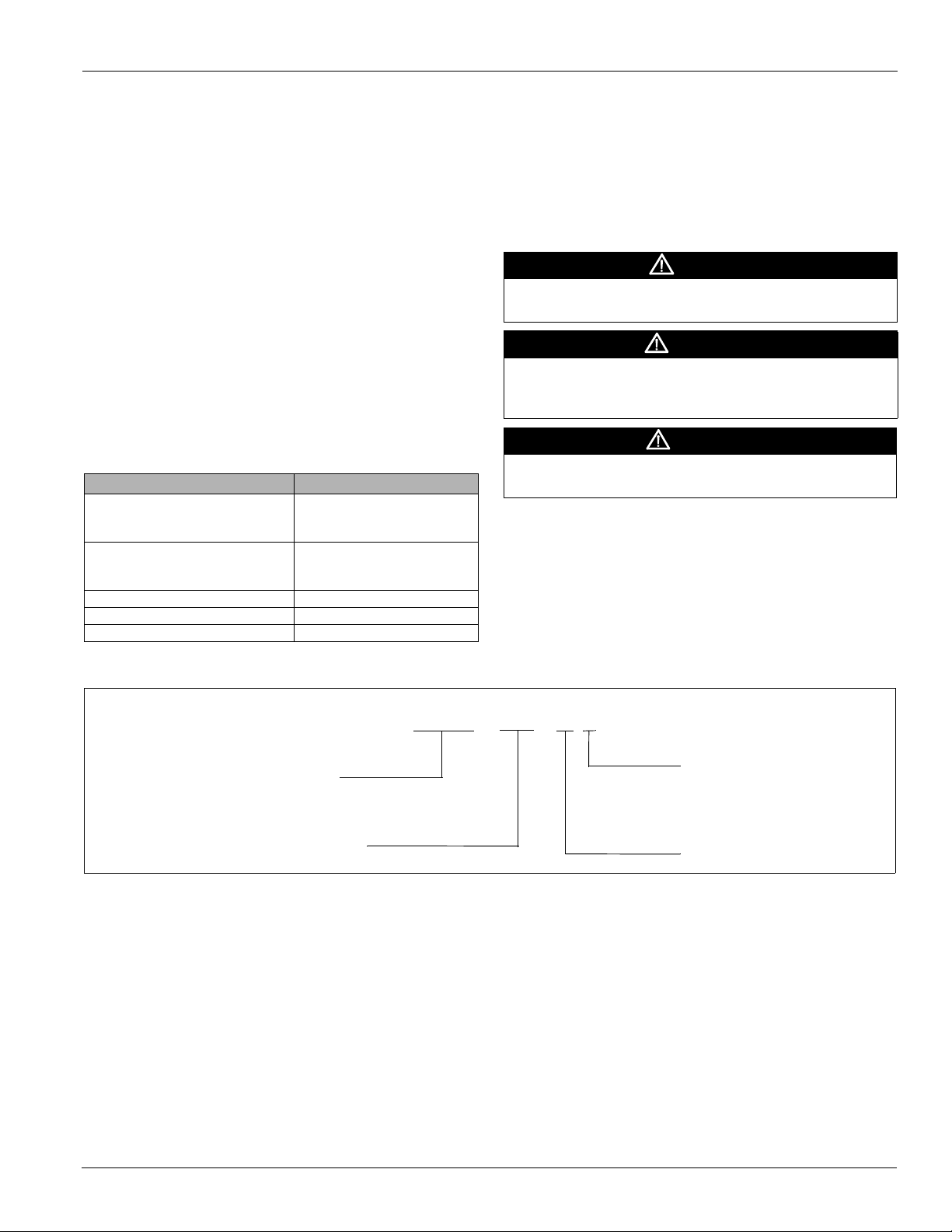
M P S – 015 – F G
McQuay Packaged System
Heat medium
Y = None (cooling only)
G = Natural gas
E = Electric heat
W = Hot water heat
Design vintage
Nominal capacity (tons)
General Information
Introduction
This manual provides general information about the “F”
vintage McQuay Commercial Packaged Rooftop Unit model
MPS. In addition to an overall description of the unit, it
includes mechanical and electrical installation procedures,
commissioning procedures, sequence of operation information,
and maintenance instructions.
The MicroTech
®
III rooftop unit controller is available on “F”
vintage rooftop units. For a detailed description of the
MicroTech III components, input/output configurations, field
wiring options and requirements, and service procedures, see
OM 920. For operation and information on using and
programming the MicroTech III unit controller, refer to the
appropriate operation manual (see Table 1).
For a description of operation and information on using the
keypad to view data and set parameters, refer to the
appropriate program-specific operation manual (see Table 1)
Table 1: Program Specific Unit Operation Literature
Rooftop unit control configuration Manual bulletin number
VFDs OM 844 - MD2
MPS Unit Controller
Discharge Air Control (VAV or CAV)
Space Comfort Control (SCC)
LonWorks Integration IM 918
BACnet Integration IM 917
BACnet IP Comm Module IM 916
OM 895 - MD3
OM 847 - MD6
OM 920
.
Unit Nameplate
The unit nameplate is located on the outside of the main
control box door. It includes the unit model number, serial
number, electrical characteristics, and refrigerant charge.
Hazard Identification Information
DANGER
Dangers indicate a hazardous situation which will result in
death or serious injury if not avoided.
WARNING
Warnings indicate potentially hazardous situations, which can
result in property damage, severe personal injury, or death if
not avoided.
CAUTION
Cautions indicate potentially hazardous situations, which can
result in personal injury or equipment damage if not avoided.
Nomenclature (MPS 015–050)
McQuay IM 1058 3
Mechanical Installation
Mechanical Installation
Installer Responsibilities
The installation of this equipment shall be in accordance with
the regulations of authorities having jurisdiction and all
applicable codes. It is the responsibility of the installer to
determine and follow the applicable codes.
CAUTION
Sharp edges on sheet metal and fasteners can cause
personal injury. This equipment must be installed, operated,
and serviced only by an experienced installation company and
fully trained personnel.
Receiving Inspection
When the equipment is received, all items should be carefully
checked against the bill of lading to be sure all crates and
cartons have been received. If the unit has become dirty
during shipment (winter road chemicals are of particular
concern), clean it when received.
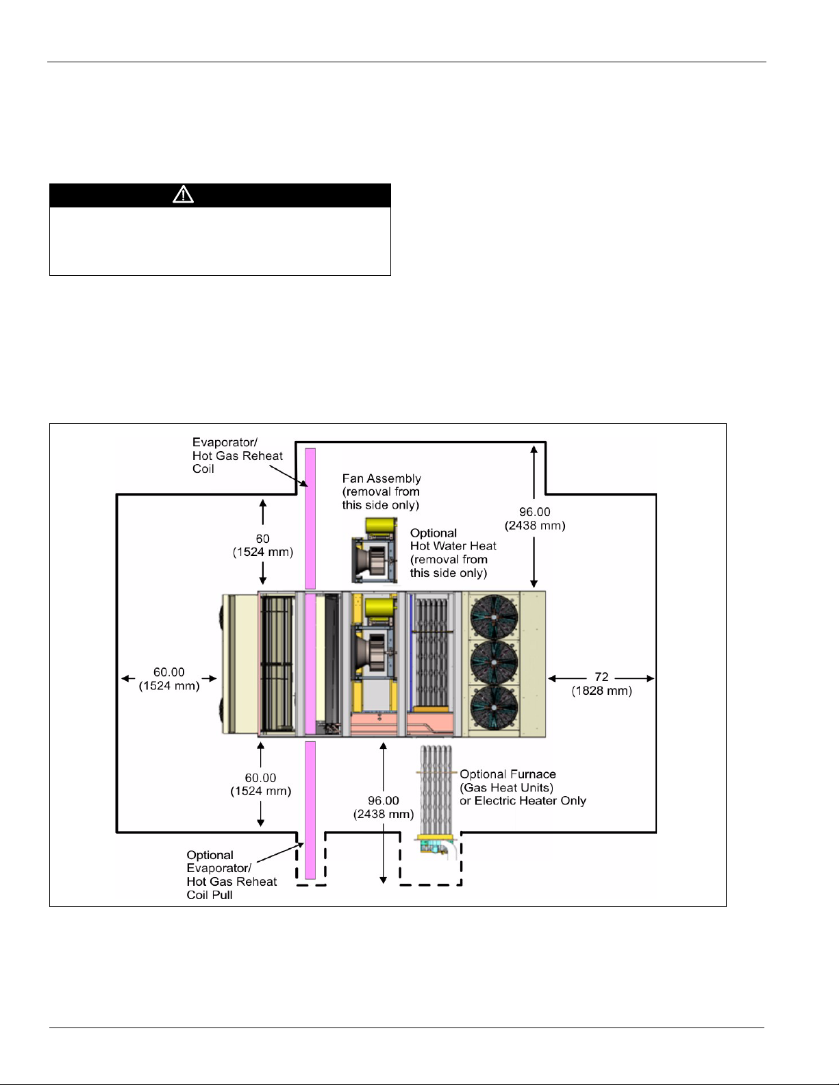
Figure 1: Service Clearances
All units should be carefully inspected for damage when
received. Report all shipping damage to the carrier and file a
claim. In most cases, equipment is shipped F.O.B. factory and
claims for freight damage should be filed by the consignee.
Before unloading the unit, check the unit nameplate to make
sure the voltage complies with the power supply available.
Service Clearance
Allow service clearances as approximately indicated in
Figure 1. Also, McQuay recommends providing a roof
walkway to the rooftop unit as well as along each side of the
unit that provides access to most controls and serviceable
components.
4 McQuay IM 1058
Mechanical Installation
Ventilation Clearance
Below are minimum ventilation clearance recommendations.
The system designer must consider each application and
provide adequate ventilation. If this is not done, the unit may
not perform properly.
Unit(s) Surrounded by a Screen or a Fence:
1 The bottom of the screen or fence should be at least 1 ft.
(305 mm) above the roof surface.
2 The distance between the unit and a screen or fence should
be as described in Figure 1 on page 4.
3 The distance between any two units within a screen or
fence should be at least 120" (3048 mm).
Unit(s) Surrounded by Solid Walls:
1 If there are walls on one or two adjacent sides of the unit,
the walls may be any height. If there are walls on more than
two adjacent sides of the unit, the walls should not be
higher than the unit.
2 The distance between the unit and the wall should be at
least 96" (2438 mm) on all sides of the unit.
3 The distance between any two units within the walls should
be at least 120" (3048 mm).
Do not locate outside air intakes near sources of contaminated
air.
If the unit is installed where windy conditions are common,
install wind screens around the unit, maintaining the
clearances specified (see Figure 1). This is particularly
important to maintain adequate head pressure control when
mechanical cooling is required at low outdoor air
temperatures.
Note: Low head pressure may lead to poor and erratic
refrigerant feed control at the thermostatic expansion
valve. The unit has automatic control of the condenser
fans which should provide adequate head pressure
control down to 20°F provided the unit is not exposed to
windy conditions. The system designer is responsible
for assuring the condensing section is not exposed to
excessive wind or air recirculation.
Overhead Clearance
1 Unit(s) surrounded by screens or solid walls must have no
overhead obstructions over any part of the unit.
2 The area above the condenser must be unobstructed in all
installations to allow vertical air discharge.
3 The following restrictions must be observed for overhead
obstructions above the air handler section:
a There must be no overhead obstructions above the
furnace flue, or within 9" (229 mm) of the flue box.
b Overhead obstructions must be no less than 96"
(2438 mm) above the top of the unit.
c There must be no overhead obstructions in the areas
above the outside air and exhaust dampers that are
farther than 24" (610 mm) from the side of the unit.
Roof Curb Assembly and Installation
Locate the roof curb and unit on a portion of the roof that can
support the weight of the unit. The unit must be supported to
prevent bending or twisting of the machine.
If building construction allows sound and vibration into
the occupied space, locate the unit over a non-critical area.
It is the responsibility of the system designer to make
adequate provisions for noise and vibration in the occupied
space.
WARNING
Mold can cause personal injury. Some materials such as
gypsum wall board can promote mold growth when damp.
Such materials must be protected from moisture that can enter
units during maintenance or normal operation.
Install the curb and unit level to allow the condensate drain to
flow properly and allow service access doors to open and close
without binding.
The gasketed top surface of the curb seals against the unit
when it is set on the curb. These flanges must not support the
total weight of the duct work. See “Installing Ductwork” on
page 12 for details on duct connections. It is critical that the
condensate drain side of the unit be no higher than the opposite
side.
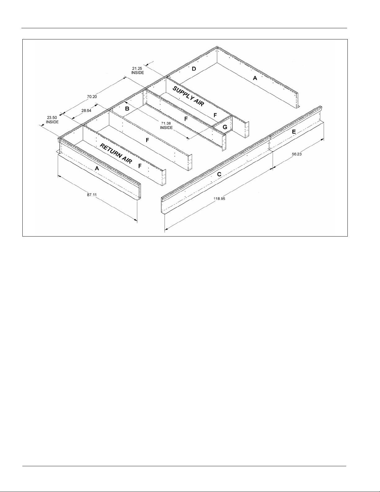
Assembly Instructions
Assembly of a typical roof curb is shown in Figure 2.
1 Set curbing parts A thru G per dimensions shown over roof
opening or on a level surface. Note location of supply air
opening. Check alignment of all mating screw holes.
2 Screw curbing parts together using fasteners provided.
Leave all screws loose until curb is checked to be square.
3 Square entire curbing assembly and securely tighten all
screws.
4 Position curb assembly over roof openings. Curb must be
level within .25 inches from side to side and 1.50 inches
over its length. Check that top surface of curb is flat with
no bowing or sagging.
5 Weld curb assembly in place. Caulk all seams watertight.
Remove backing from .25 x 1.50 wide gasket and apply to
surfaces shown by crosshatching.
6 Check that electrical connections are coordinated.
McQuay IM 1058 5
Mechanical Installation
Figure 2: Roof Curb Assembly (MPS 030F – 035F Example)
6 McQuay IM 1058
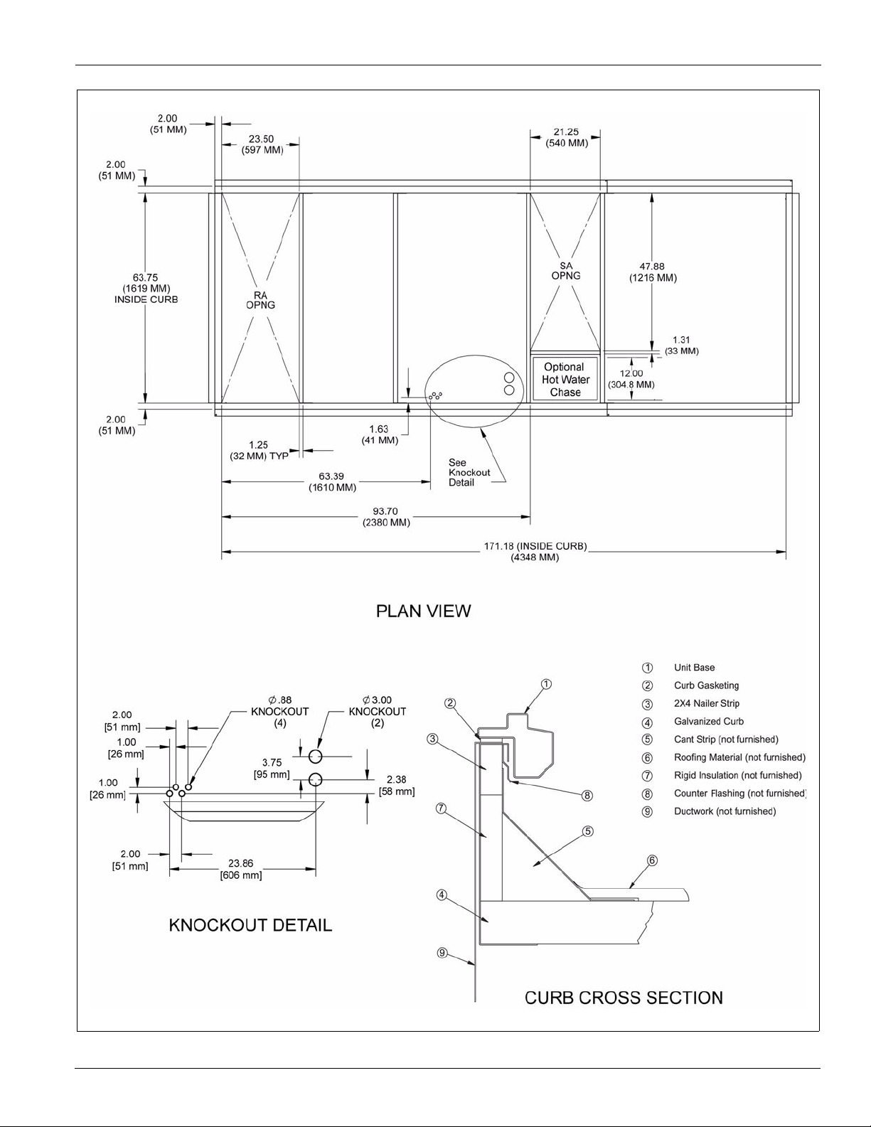
Figure 3: Roof Curb Layout—MPS 015F – 025F
Mechanical Installation
McQuay IM 1058 7
23.50
[597 mm]
2.00
[51 mm]
2.00
[51 mm]
21.25
[540 mm]
71.38
[1813 mm]
15.87
[403 mm]
87.25
[2216 mm]
(INSIDE CURB)
1.25
[32 mm] TYP
1.63
[41 mm]
93.70
[2380 mm]
171.18 (INSIDE CURB)
[4348 mm]
63.69
[1610 mm]
2.00
[51 mm]
2.00
[51 mm]
1.00
[26 mm]
1.00
[26 mm]
2.00
[51 mm]
2.38
[58 mm]
3.75
[95 mm]
PLAN VIEW
23.86
[606 mm]
CURB CROSS SECTION
KNOCKOUT DETAIL
F
HOT WATER
ONLY
CHASE
1.00
[25 mm]
19.00
[483 mm]
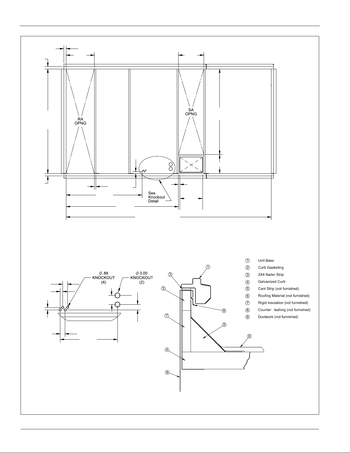
Mechanical Installation
Figure 4: Roof Curb Layout—MPS 030F – 035F
8 McQuay IM 1058
CURB CROSS SECTION
2.00
[51 mm]
2.00
[51 mm]
30.63
[778 mm]
87.25
[2216 mm]
(INSIDE CURB)
2.00
[51 mm]
1.25 TYP
[32 mm]
1.63
[41 mm]
69.39
[1763 mm]
105.45
[2678 mm]
208.57 (INSIDE CURB)
[5298 mm]
71.38
[1813 mm]
15.87
[403 mm]
28.25
[718 mm]
2.00
[51 mm]
2.00
[51 mm]
1.00
[25 mm]
2.28
[58 mm]
3.75
[95 mm]
28.92
[735 mm]
PLAN VIEW
F
1.00
[25 mm]
26.00
[660 mm]
HOT WATER
ONLY
CHASE
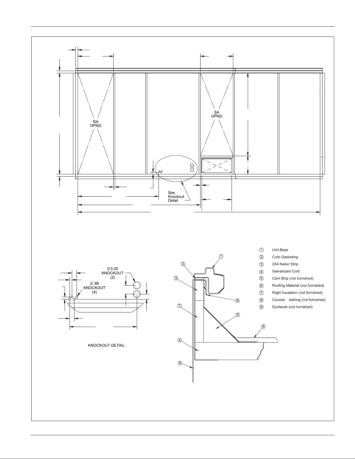
Figure 5: Roof Curb Layout—MPS 040F – 050F
Mechanical Installation
McQuay IM 1058 9
Mechanical Installation
LIFT UNIT ONLY AS SHOWN
SPREADER BARS REQUIRED
MUST USE ALL OF THESE
LIFTING LUGS FOR LIFTING UNIT.
Rigging and Handling
WARNING
Only trained and qualified personnel should be allowed to
rig loads or operate load rated cranes and/or hoist
assemblies. Do not use a forklift to lift or maneuver the
unit. Failure to use a load rated crane or hoist assembly to
lift or maneuver the unit can cause severe personal injury
and property damage.
WARNING
Use all lifting points. Improper lifting can cause property
damage, severe personal injury, or death.
CAUTION
Lifting points may not be symmetrical to the center of
gravity of the unit. Ballast or unequal cable lengths may be
required.
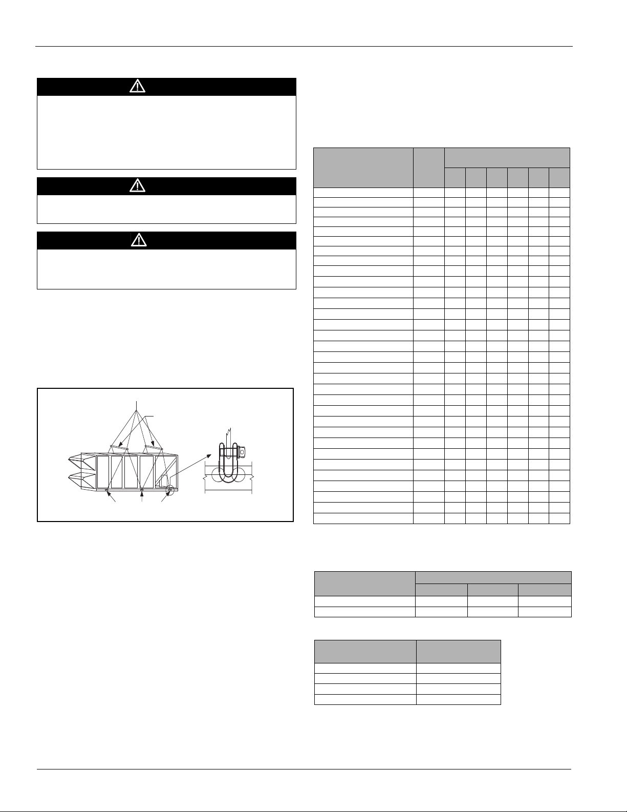
Rigging holes for shackles are integral on the unit base. All six
lifting points must be used for rigging the equipment. Use
four independent lines, securing one end of a line to a unit
base lifting point and the other end of the line to an
associated spreader bar lifting point (see Figure 7). Figure 6
is an example of an instruction label shipped with each unit.
Figure 6: Rigging Label
Use spreader bars, 96" to 100" (2438 to 2540 mm) wide to
prevent damage to the unit cabinet. Avoid twisting or uneven
lifting of the unit. The cable length from the bracket to the
hook should always be longer than the distance between the
outer lifting points.
If the unit is stored at the construction site for an intermediate
period, take these additional precautions:
1 Support the unit well along the length of the base rail.
2 Level the unit (no twists or uneven ground surface).
3 Provide proper drainage around the unit to prevent flooding
of the equipment.
4 Provide adequate protection from vandalism, mechanical
contact, etc.
5 Securely close the doors.
6 Cover the supply and return air openings.
Table 2 lists the weight distribution at each of the six lifting
points on the unit (refer to Figure 7 on page 11). Table 3 details
lifting point locations.
Table 2: Percentage of Load and Weight Points
Unit (tons)
015 Cooling 2655 292 292 531 637 425 478
015 Gas Heating 2855 315 315 571 685 457 514
015 Electric Heating 2775 305 304 555 666 444 500
015 Hot Water Heating 2850 314 314 570 684 456 513
017 Cooling 2705 298 298 541 649 433 487
017 Gas Heating 2905 320 320 581 697 465 523
017 Electric Heating 2825 311 311 565 678 452 509
017 Hot Water Heating 2900 319 319 580 696 464 522
020 Cooling
020 Gas Heating
020 Electric Heating
020 Hot Water Heating
025 Cooling
025 Gas Heating
025 Electric Heating
025 Hot Water Heating
030 Cooling 3610 397 397 722 866 578 650
030 Gas Heating 3880 427 427 776 931 621 698
030 Electric Heating 3880 427 427 776 931 621 698
030 Hot Water Heating 3901 429 429 780 936 624 702
035 Cooling 3660 403 403 732 878 586 659
035 Gas Heating 3930 432 432 786 943 629 707
035 Electric Heating 3930 432 432 786 943 629 707
035 Hot Water Heating 3961 435 435 790 948 632 711
040 Cooling 4685 515 515 937 1124 750 843
040 Gas Heating 5035 554 554 1007 1208 806 906
040 Electric Heating 5035 554 554 1007 1208 806 906
040 Hot Water Heating 4992 549 549 998 1198 799 899
050 Cooling 4985 548 548 997 1196 798 897
050 Gas Heating 5335 587 587 1067 1280 854 960
050 Electric Heating 5335 587 587 1067 1280 854 960
050 Hot Water Heating 5292 582 582 1058 1270 847 953
*
Base unit weight includes Economizer, VFDs, and the smallest supply fan
available (see Table 5 and Table 6 on page 11 for additional fan/motor
weights).
Table 3: Weight Distribution Locations (see Figure 7)
Unit (Tons)
015–035 Ton Unit 35.5 62.0 52.0
040–050 Ton Unit 40.0 69.0 89.0
Table 4: Curb Weights
Unit (Tons) / Curb
Height
015–035 / 14" Curb 341
015–035 / 24" Curb 501
040–050 / 14" Curb 481
040–050 / 24" Curb 708
Table 4 lists the weights of unit curbs.
Tot al
Weight
(lbs)*
2955 325 325 591 709 473 532
3155 347 347 631 757 505 568
3075 338 338 615 738 492 554
3150 347 347 630 756 504 567
3055 336 336 611 733 489 550
3255 358 358 651 781 521 586
3175 349 349 635 762 508 572
3250 358 358 650 780 520 585
A
11%B11%C20%D24%E16%F18%
L1 L2 L3
Weight (lbs)
Point
% of Total Load
Distance
10 McQuay IM 1058
Mechanical Installation
Figure 7: Rigging the Unit (MPS 030 – 035 Example)
Additional Weights for Motors/Exhaust Fans
Table 5: Additional Weights - Motors/Exhaust Fans (20 - 25
ton units)
HP
1 0 15 - 25 150
1.5 9
29
332
543
Table 6: Additional Weights - Motors/Exhaust Fans (30 - 50
ton units)
HP
7.5 0 30 150
10 25 35 150
15 125 40 200
20 175 50 200
25 225
30 275
Additional Motor
Weight (lbs)
Additional Motor
Weight (lbs)
Unit
(tons)
Unit
(tons)
Additional Exhaust
Fan Weight (lbs)
Additional Exhaust
Fan Weight (lbs)
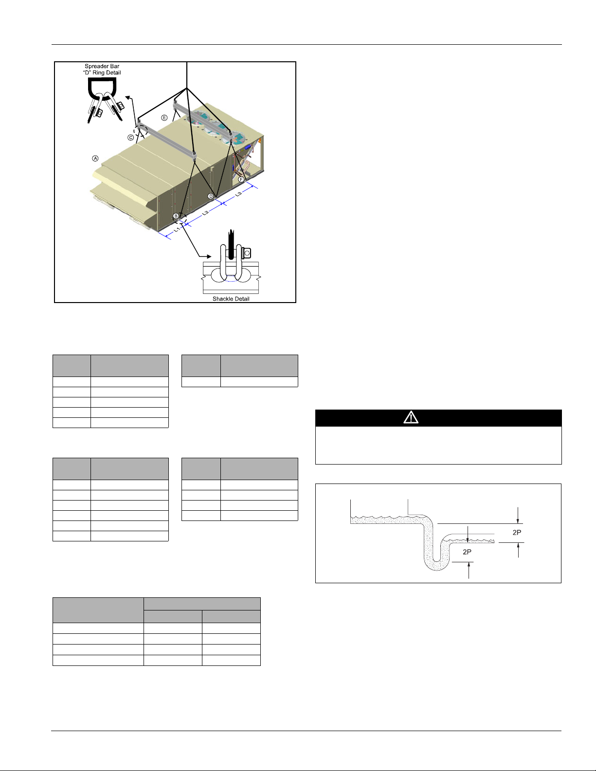
Unit Piping - Condensate Drain Connection
The unit is provided with a 1" female NPT condensate drain
connection. For proper drainage, level the unit and drain pan
side to side and install a P-trap.
Figure 8 shows the layout of the condensate drain connection.
The distance from the drain pan outlet to the horizontal run of
the P-trap should be a distance of twice the static pressure in
the drain pan.
Example: If the static pressure as measured in the drain pan is
1.5", then the distance between the drain outlet and the
horizontal run should be 3".
Draining condensate directly onto the roof may be acceptable;
refer to local codes. Provide a small drip pad of stone, mortar,
wood, or metal to protect the roof against possible damage.
If condensate is piped into the building drainage system, pitch the
drain line away from the unit a minimum of 1/8" per foot. The
drain line must penetrate the roof external to the unit. Refer to
local codes for additional requirements. Sealed drain lines require
venting to provide proper condensate flow.
Where the cooling coils have intermediate condensate pans on
the face of the evaporator coil, copper tubes near both ends of
the coil supply drainage to the main drain pan. Verify the tubes
are in place and open before putting the unit into operation.
Periodically clean to prevent microbial growth/algae buildup
from plugging the drain and causing the drain pan to overflow.
Clean drain pans to prevent the spread of disease. Cleaning
should be performed by qualified personnel
WARNING
Drain pans must be cleaned periodically. Material in
uncleaned drain pans can cause disease.
Cleaning should be performed by qualified personnel.
Figure 8: Condensate Drain Connection
Static Pressure (P)
at the Drain Pan
.
Additional Weights for 6-Row DX Coil and HGRH Coil
Table 7: Coil Weights
Unit
15–25 118 70
30–35 164 82
40 187 92
50 231 92
McQuay IM 1058 11
Weight (lbs)
6 Row DX HGRH
Mechanical Installation
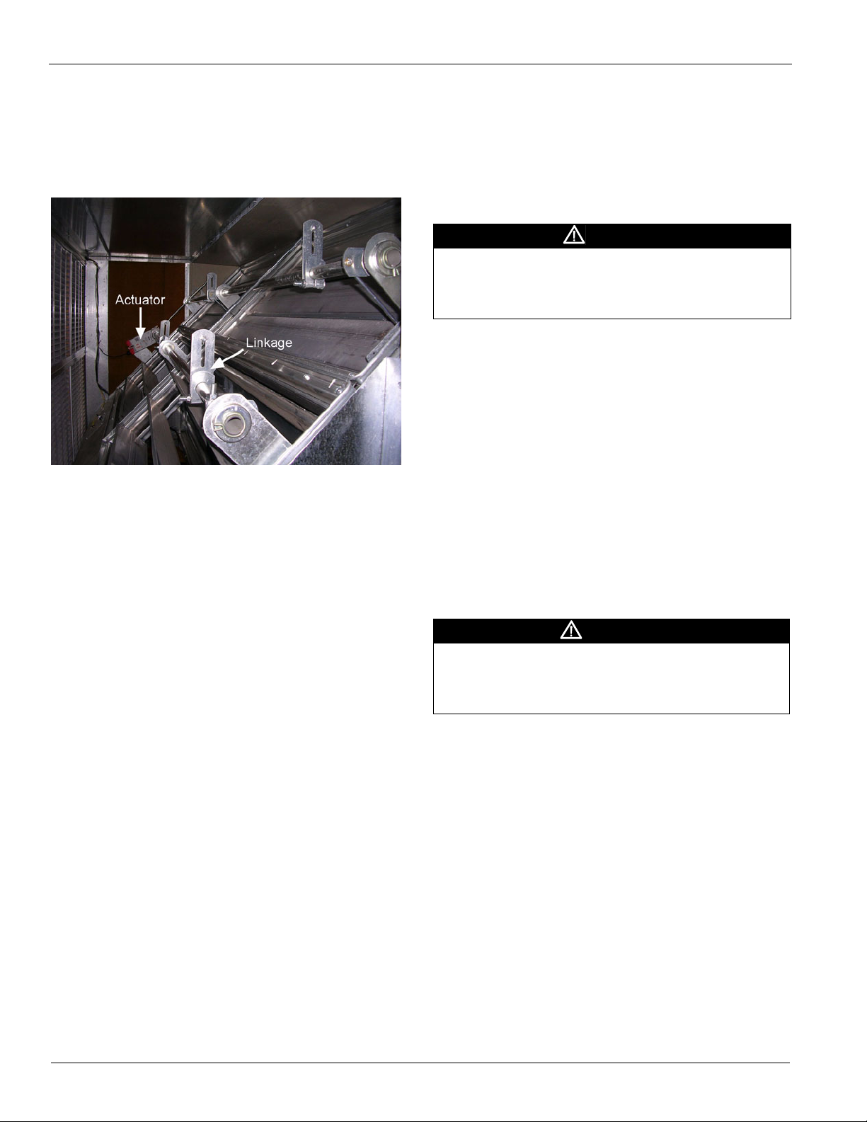
Damper Assemblies
The optional damper assemblies described in this section are
ordered with factory-installed actuators and linkages. The
following sections describe the operation and linkage
adjustment of the factory option.
Figure 9: Damper Assembly
Economizer Dampers
As the single actuator modulates, the outside air dampers open,
the return air dampers close, and the exhaust air exits the unit
through the gravity relief dampers.
The economizer comes with manually adjustable linkage
(Figure 9). The damper is set so that the crankarm moves
through a 90-degree angle to bring the economizer dampers
from full open to full close. Mechanical stops are placed in the
crankarm mounting bracket. Do not remove stops. Driving the
crankarm past the stops results in damage to the linkage or
damper.
Outdoor Air Dampers (0% to 30%)
These dampers are intended to remain at a fixed position
during unit operation, providing fresh air quantities from 0 to
30% of the total system airflow, depending on the damper
setting.
The damper position may be set at the unit controller keypad
(refer to OM 920 for further detail). During unit operation, the
damper is driven to the position set at the unit controller.
During the off cycle, the damper is automatically closed.
Cabinet Weather Protection
This unit ships from the factory with fully gasketed access
doors and cabinet caulking to provide weather resistant
operation. After the unit is set in place, inspect all door gaskets
for shipping damage and replace if necessary.
Protect the unit from overhead runoff from overhangs or other
such structures.
CAUTION
Transportation, rigging, or maintenance can damage the
unit’s weather seal. Periodically inspect the unit for leakage.
Standing moisture can promote microbial growth, disease, or
damage to the equipment and building.
Installing Ductwork
On vertical-supply/vertical-return units, if a McQuay roof curb
is not used, the installing contractor should make an airtight
connection by attaching field fabricated duct collars to the
bottom surface of the unit’s duct opening. Do not support the
total weight of the duct work from the unit. See Figure 4 on
page 8 or Figure 5 on page 9.
Use flexible connections between the unit and ductwork to
avoid transmission of vibration from the unit to the structure.
To minimize losses and sound transmission, design duct work
per ASHRAE and SMACNA recommendations.
Where return air ducts are not required, connect a sound
absorbing T or L section to the unit return to reduce noise
transmission to the occupied space.
WARNING
Mold can cause personal injury. Materials such as gypsum
wall board can promote mold growth when damp. Such
materials must be protected from moisture that can enter units
during maintenance or normal operation.
Ductwork exposed to outdoor conditions must be built in
accordance with ASHRAE and SMACNA recommendations
and local building codes
.
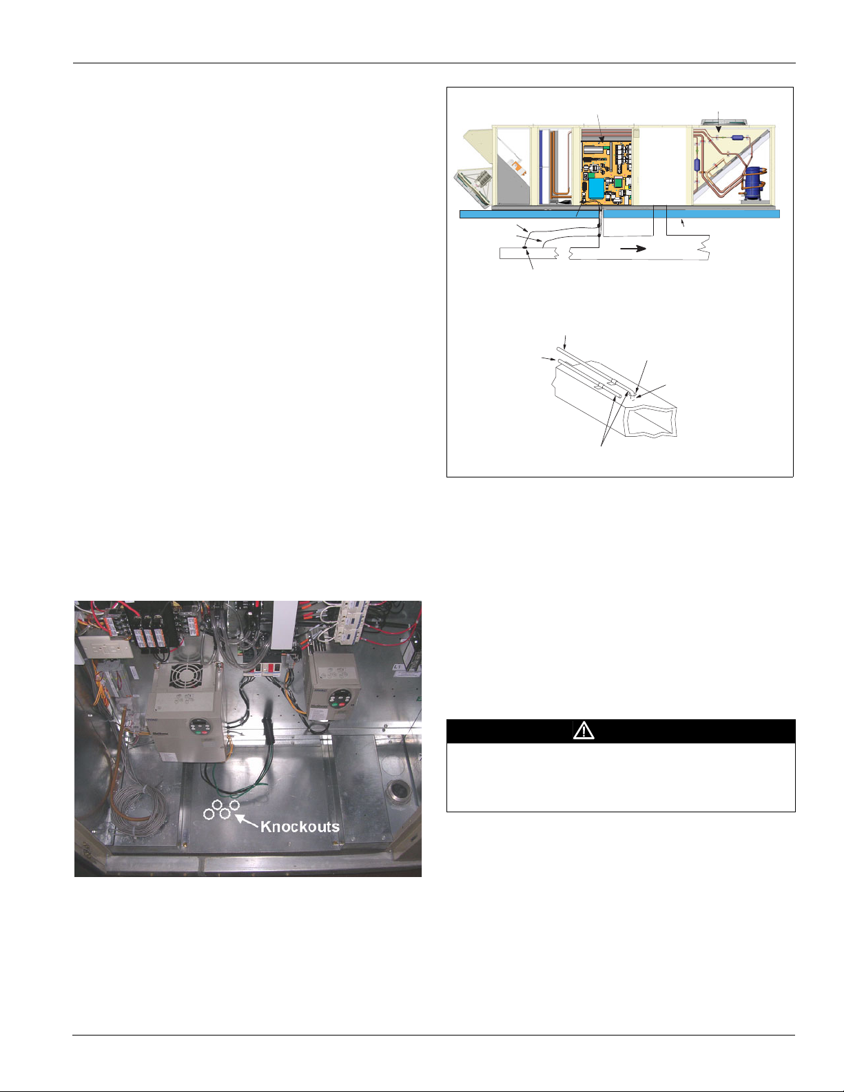
Installing Duct Static Pressure Sensor Taps
For all VAV units, duct static pressure taps must be field
installed and connected to the static pressure sensor 1 (SPS1)
in the unit. Sensor SPS1 is standard on VAV units and is
located in the main control panel.
Carefully locate and install the duct static pressure sensing tap.
Improperly locating or installing the sensing tap causes
unsatisfactory operation of the entire variable air volume
system. Below are pressure tap location and installation
recommendations. The installation must comply with local
code requirements.
12 McQuay IM 1058
Mechanical Installation
Roof
SPS1
Main Control Panel
Condenser Section
HI Line
LO Line
Remote Sense Point
To Sensor
HI Input
Pressure Sensing
Tubing
Tubing Extends
Through Approx. 1/8”
Rubber
Grommet
Ductwork
(Remote Location)
To Sensor
LO Input
1 Install a tee fitting with a leak-tight removable cap in each
tube near the sensor fitting. This facilitates connecting a
manometer or pressure gauge if testing is required.
2 Use different colored tubing for the duct pressure (HI) and
reference pressure (LO) taps, or tag the tubes. McQuay
recommends 1/8" ID tubing.
3 Locate the duct pressure (HI) tap near the end of a long
duct to ensure that all terminal box take-offs along the run
have adequate static pressure.
4 Locate the duct tap in a nonturbulent flow area of the duct.
Keep it several duct diameters away from take-off points,
bends, neckdowns, attenuators, vanes, or other
irregularities.
5 Use a static pressure tip (Dwyer A302 or equivalent) or the
bare end of the plastic tubing for the duct tap. (If the duct is
lined inside, use a static pressure tip device.)
6 Install the duct tap so that it senses only static pressure (not
velocity pressure). If a bare tube end is used, it must be
smooth, square (not cut at an angle) and perpendicular to
the airstream (see Figure 11).
7 Locate the reference pressure (LO) tap near the duct
pressure tap within the building. If the tap is not connected
to the sensor, unsatisfactory operation will result.
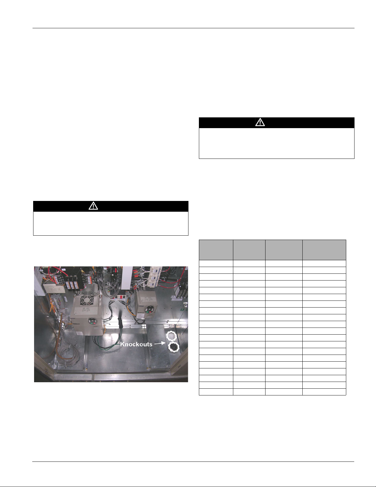
8 Route the tubes through the curb and feed them into the
unit through the knockout in the bottom of the control panel
(see Figure 10). Connect the tubes to appropriate barbed
fittings (on SPS1) in the control panel. (Fittings are sized to
accept 1/8" ID tubing.)
Figure 10: Static Pressure Tubing Knockout Location
Figure 11: Duct Static Pressure Sensing Tubing Installation
Installing Building Static Pressure Sensor Taps
If a unit has building static pressure control capability, you
must field install and connect static pressure taps to the static
pressure sensor SPS2 in the unit. This sensor is located at the
bottom of the main control panel next to SPS1.
Carefully locate and install the two static pressure sensing
taps. Improper location or installation of the sensor taps causes
unsatisfactory operation. Below are pressure tap location and
installation recommendations for both building envelope and
lab, or “space within a space” pressure control applications.
The installation must comply with local code requirements.
CAUTION
Fragile sensor fittings. If you must remove tubing from a
pressure sensor fitting, use care. Do not use excessive force or
wrench the tubing back and forth to remove or the fitting can
break off and damage sensor.
McQuay IM 1058 13
Mechanical Installation
Building Pressurization Applications
1 Install a tee fitting with a leak-tight removable cap in each
tube near the sensor fitting. This facilitates connecting a
manometer or pressure gauge if testing is required.
2 Locate the building pressure (high) tap in the area that
requires the closest control. Typically, this is a ground level
floor that has doors to the outside.
3 Locate the building tap so it is not influenced by any source
of moving air (velocity pressure). These sources may
include air diffusers or outside doors.
4 Route the building tap tube through the curb and feed it into
the unit through the knockout in the bottom of the control
panel (refer to Figure 10). Connect the 1/8" ID tube to the
(high) fitting for sensor SPS2.
5 Locate the reference pressure (low) tap on the roof. Keep it
away from the condenser fans, walls, or anything else that
may cause air turbulence. Mount it high enough above the
roof so it is not affected by snow. Not connecting the
reference tap to the sensor results in unsatisfactory
operation.
6 Use an outdoor static pressure tip (Dwyer A306 or
equivalent) to minimize the adverse effects of wind. Place
some type of screen over the sensor to keep out insects.
Loosely packed cotton works well.
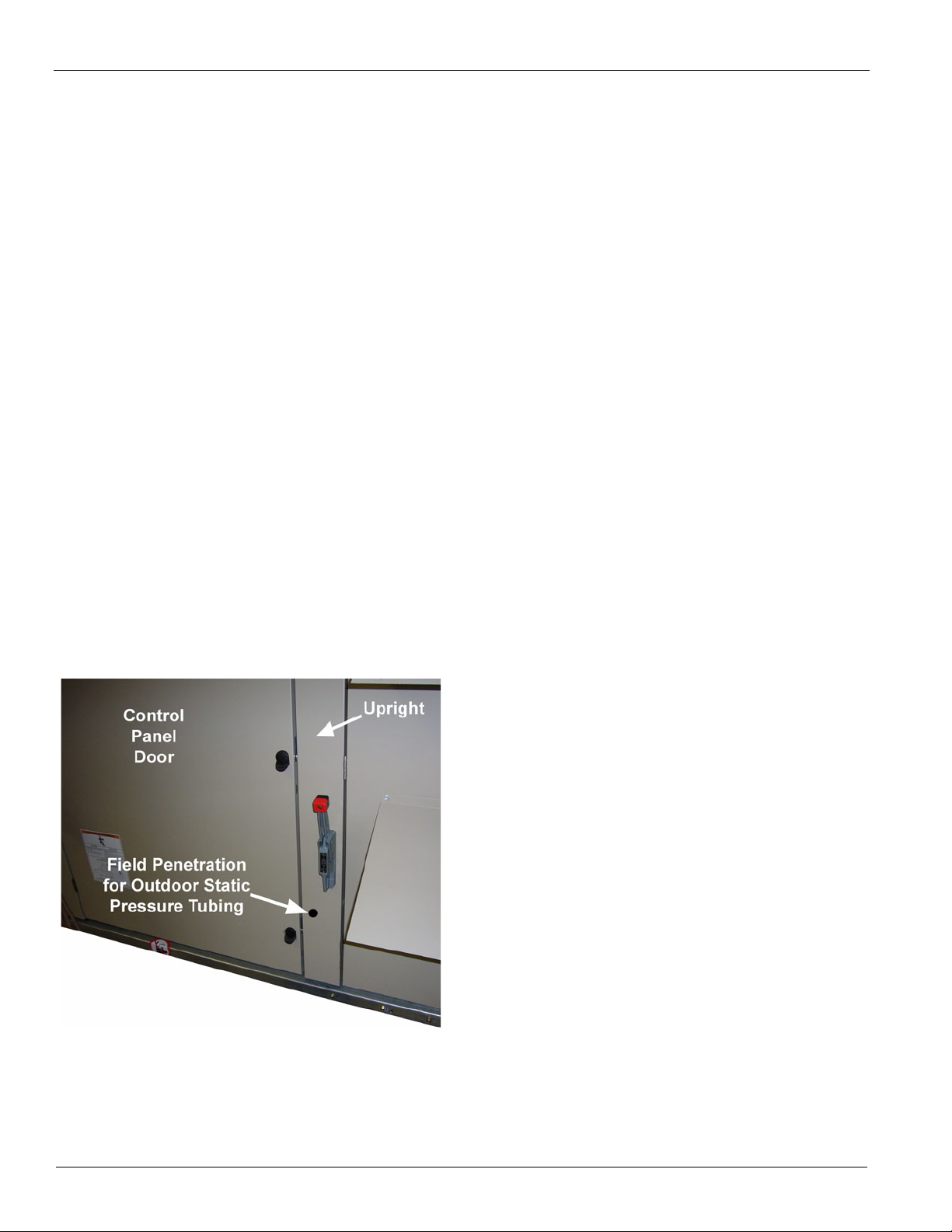
7 Route the outdoor tap tube out of the main control panel
through a small field-cut opening in the upright. Seal the
penetration to prevent water from entering. Connect the
1/8" ID tube to the (low) fitting for sensor SPS2.
Lab Pressurization Applications
1 Install a “T” fitting with a leak-tight removable cap in each
tube near the sensor fitting. This facilitates connecting a
manometer or pressure gauge if testing is required.
2 Use different colored tubing for the controlled space
pressure (high) and reference pressure (low) taps, or tag the
tubes.
3 Regardless whether the controlled space is positive or
negative with respect to its reference, locate the high
pressure tap in the controlled space (the setpoint can be set
between -0.2" and 0.2" wc).
4 Locate the reference pressure (low) tap in the area
surrounding the controlled space. Not locating the
reference tap to the sensor results in unsatisfactory
operation.
5 Locate both taps so they are not influenced by any source
of moving air (velocity pressure). These sources may
include air diffusers or doors between the high and low
pressure areas.
6 Route the building tap tube between the curb and the
supply duct and feed it into the unit through the knockout in
the bottom of the control panel.
7 Connect the tube to the (high) fitting for sensor SPS2.
Figure 12: Outdoor Static Pressure Tubing Installation
14 McQuay IM 1058
Electrical Installation
Electrical Installation
Field Power Wiring
Wiring must comply with all applicable codes and ordinances.
The warranty is voided if wiring is not in accordance with
these specifications.
According to the National Electrical Code, a disconnecting
means shall be located within sight of and readily accessible
from the air conditioning equipment. The unit can be ordered
with an optional factory mounted disconnect switch. This
switch is not fused. Power leads must be over-current
protected at the point of distribution. The maximum rated
overcurrent protection device (MROPD) value appears on the
unit nameplate.
All Units
All units are provided with internal power wiring for single
point power connection. The power block or an optional
disconnect switch is located within the main control panel.
Field power leads are brought into the unit through knockouts
in the bottom of the main control panel (see Figure 13 and also
Table 8). Refer to the unit nameplate to determine the number
of power connections.
WARNING
Hazardous voltage. Can cause severe injury or death.
Disconnect electric power before servicing equipment. More
than one disconnect may be required to de-energize the unit.
Note: To wire entry points, refer to certified drawings for
dimensions.
Figure 13: MPS Power Wiring Knockout Locations
The preferred entrance for power cables is through the bottom
knockouts provided on the unit. If a side entrance is the only
option, a hole may be drilled in the stationary upright.
The minimum circuit ampacity (MCA) is shown on the unit
nameplate. Refer to Table 8 for the recommended number of
power wires.
Copper wire is required for all conductors. Size wires in
accordance with the ampacity tables in Article 310 of the
National Electrical Code. If long wires are required, it may be
necessary to increase the wire size to prevent excessive voltage
drop. Wires should be sized for a maximum of 3% voltage
drop. Supply voltage must not vary by more than 10% of
nameplate. Phase voltage imbalance must not exceed 2%.
(Calculate the average voltage of the three legs. The leg with
voltage deviating the farthest from the average value must not
be more than 2% away.) Contact the local power company for
correction of improper voltage or phase imbalance.
CAUTION
Provide proper line voltage and phase balance.
Improper line voltage or excessive phase imbalance constitutes
product abuse. It can cause severe damage to the unit's
electrical components.
A ground lug is provided in the control panel. Size the
grounding conductor in accordance with Table 250-95 of the
National Electrical Code.
In compliance with the National Electrical Code, a 115 V
factory mounted service receptacle outlet is provided. This
outlet must be powered by a field connected 15 A, 115 V
power supply. Leads are brought into the unit through a 7/8"
knockout in the bottom of the main control panel.
Table 8: Recommended Field Power Wiring
Ampacity
(MCA)
30 1 10 75
40 1 8 75
55 1 6 75
70 1 4 75
85 1 3 75
95 1 2 75
130 1 1 75
150 1 1/0 75
175 1 2/0 75
200 1 3/0 75
230 1 4/0 75
255 1 250 75
300 2 1/0 75
350 2 2/0 75
400 2 3/0 75
460 2 4/0 75
510 2 250 75
600 3 3/0 75
690 3 4/0 75
765 3 250 75
Notes:
1. All wire sizes assume separate conduit for each set of parallel conductors.
2. All wire sizes based on NEC Table 310-16 for 75°C THW wire (copper).
Canadian electrical code wire ampacities may vary.
3. All wire sizes assume no voltage drop for short power leads.
# of Power
Wires Per
Phase
Wire Gauge
Insulation
Temperature
Rating (°C)
McQuay IM 1058 15
Electrical Installation
Field Control Wiring
The Maverick rooftop units are available with the following
field control connections:
• Space sensor.
• Space sensor with setpoint adjustment.
• Fan operation output.
• VAV box output.
• Remote alarm output.
• External discharge air temperature reset.
• Outdoor air damper minimum position adjustment.
Descriptions of these field connections are included in the
MicroTech III Unit Controller manual (OM 920).
WARNING
Electrical shock hazard. Can cause severe injury or death.
Connect only low voltage NEC Class II circuits to terminal block
TB2.
16 McQuay IM 1058
Preparing Unit for Operation
Preparing Unit for Operation
Spring Isolated Fans
WARNING
Moving machinery hazard. Can cause severe injury or
death. Before servicing equipment, disconnect power and lock
off. More than one disconnect may be required to de-energize
unit. Prior to operating the fans for the first time, refer to “Check,
Test, and Start Procedures” on page 52.
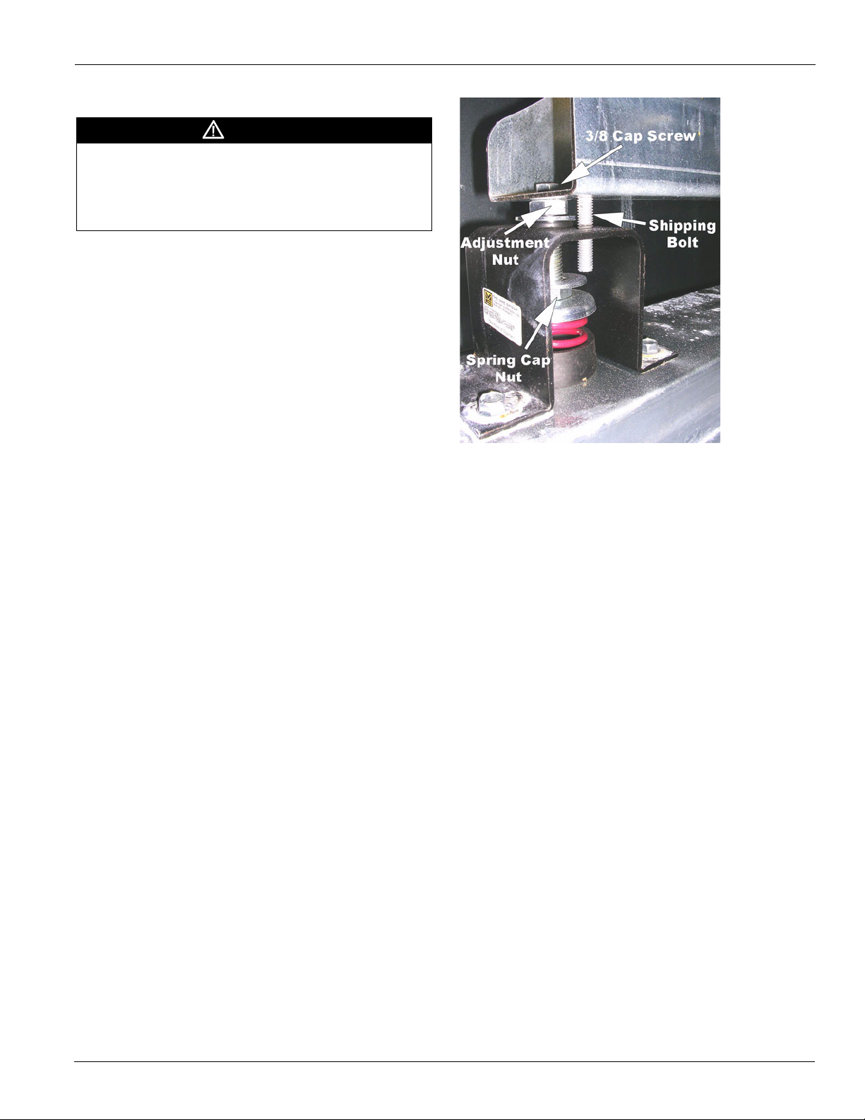
Releasing Spring Mounts
The spring-mounted supply fan is locked down with four
shipping bolts for shipment. Remove each shipping bolt before
operating the fans. Figure 14 shows a typical spring mount
with a height adjustment nut and a shipping bolt.
After removing the shipping bolts, rock the fan assembly by
hand to check for freedom of movement.
Figure 14: Spring Mounts
Adjusting Spring Mounts
During operation all fans should ride level. Level the fan
assembly by performing the following:
1 Loosen the 3/8" cap screw (do not remove).
2 Loosen the spring cap nut.
3 Rotate the 5/8" adjustment nut counter-clockwise to raise
the fan assembly, or clockwise to lower the fan assembly.
4 Tighten the 3/8" cap screw.
5 Tighten the spring cap nut.
McQuay IM 1058 17
Optional Gas Heat
Optional Gas Heat
Gas Furnace Design
If the 8th digit in the model number is a “G”, the rooftop unit
was furnished with a factory installed furnace (Example,
MPS035FG). The Maverick commercial rooftop units are
available with either the low heat input or the high heat input
furnace (see capacities in Table 9). This packaged gas heat
rooftop unit is designed for outdoor non-residential
installations only.
The gas heat furnace design consists of a tubular heat
exchanger, in-shot burner manifold with gas valve, induced
combustion blower, gas heat DDC control module and all
operational safeties. The tubular heat exchanger can come with
the standard aluminized steel construction or the optional
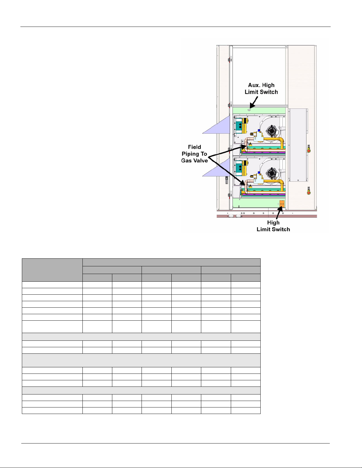
stainless steel construction. The safety switches include a highlimit temperature switch (Figure 15), an auxiliary high-limit
switch (Figure 15), a combustion blower proof of airflow (see
Figure 16), and the flame roll-out switch (see Figure 16).
The high limit switch is an automatic reset switch and it opens
up at 160°F to shut the furnace down and closes at 130°F. The
auxiliary limit switch is a manual reset and opens up at 180°F
to shut the furnace down.
Figure 15: Gas Heat Section
Gas Heating Capacity Data
Table 9: MPS 020E – 050E Gas Heating Capacities
Unit Size
Data
Heating Input (MBh) 240 480 300 600 400 800
Heating Output (MBh) 192 384 240 480 320 640
Steady State Efficiency 80% 80% 80% 80% 80% 80%
Number of Stages 2 4 2 4 2 4
Turndown
Minimum Airflow 2960 5920 3700 7400 4900 9800
Maximum Temperature
Gas Main Pressure
Natural Gas (in. wc) 7-14 7-14 7-14 7-14 7-14 7-14
Liquid Propane (in. wc) 12-14 12-14 12-14 12-14 12-14 12-14
Manifold Pressure
Natural Gas (per gas valve)
Stage 1 (in. wc) 1.2 1.2 1.2 1.2 1.2 1.2
Stage 2 (in. wc) 3.2 3.2 3.2 3.2 3.2 3.2
Low fire
Propane
Stage 1 (in. wc) 2.3 2.3 2.3 2.3 2.3 2.3
Stage 2 (in. wc) 10.0 10.0 10.0 10.0 10.0 10.0
Low fire
Note: 1 Modulating gas heat only.
2
Modulating gas heat not available with propane.
1
Rise
2
2
015 -025 030 - 035 040 - 050
Low Heat High Heat Low Heat High Heat Low Heat High Heat
4:18:14:18:14:18:1
60°F 60°F 60°F 60°F 60°F 60°F
0.40.40.40.40.40.4
N/A N/A N/A N/A N/A N/A
18 McQuay IM 1058
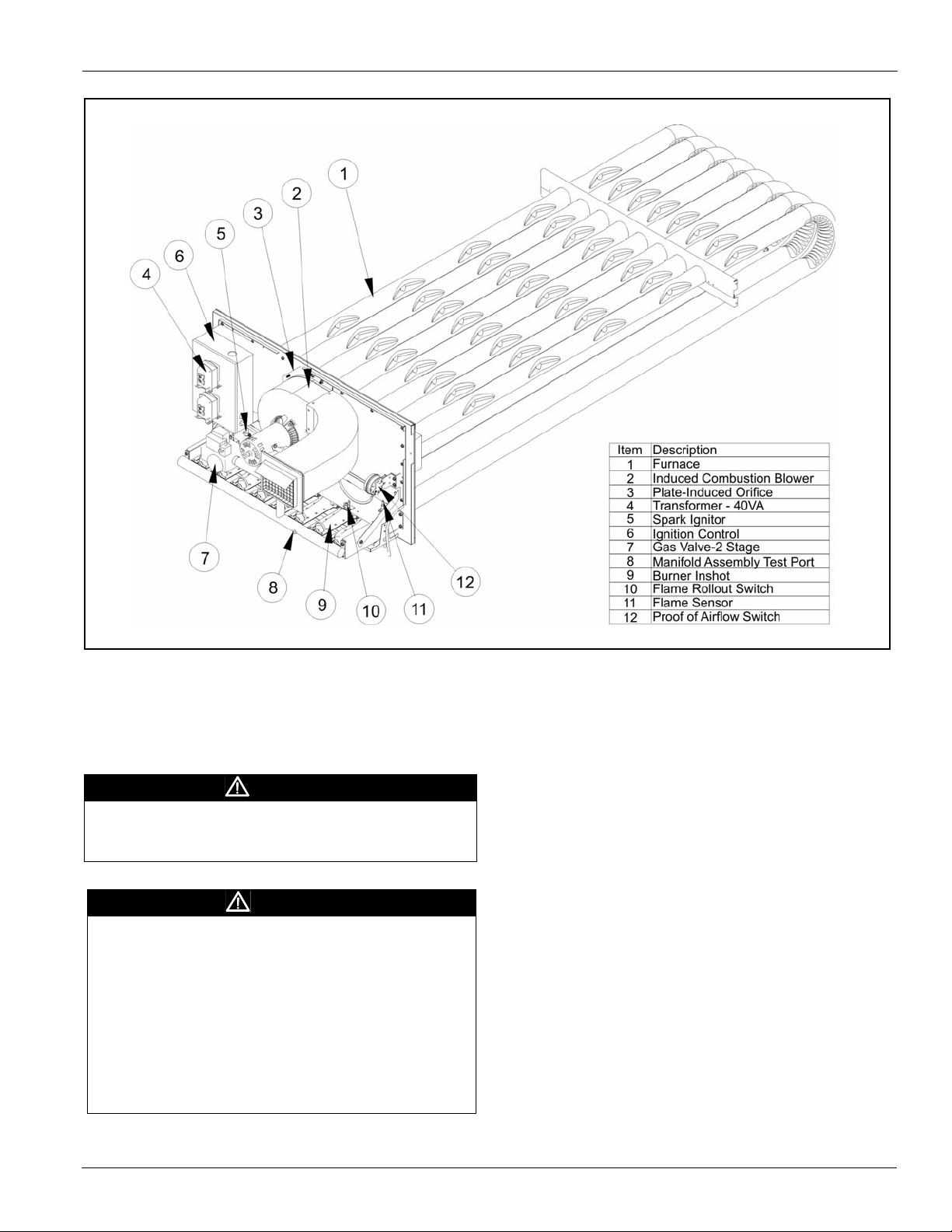
Figure 16: Staged Furnace Assembly
Optional Gas Heat
Warranty Exclusion
Warranty is void if the furnace is operated in the presence of
chlorinated vapors, if the airflow through the furnace is not in
accordance with rating plate, or if the wiring or controls have
been modified or tampered with.
WARNING
Hot surface hazard. Can cause severe equipment damage,
personal injury, or death. Allow burner assembly to cool
before servicing equipment.
WARNING
Units equipped with gas heating must not be operated in
an atmosphere contaminated with chemicals which will
corrode the unit such as halogenated hydrocarbons,
chlorine, cleaning solvents, refrigerants, swimming pool
exhaust, etc. Exposure to these compounds may cause
severe damage to the gas furnace and result in improper
or dangerous operation. Operation of the gas furnace in such
a contaminated atmosphere constitutes product abuse and will
void all warranty coverage by the manufacturer. Questions
regarding specific contaminants should be referred to your
local gas utility.
Ventilation & Flue Pipe Requirements
The McQuay rooftop unit is equipped with an outdoor air hood
to supply adequate combustion air. The unit also has a flue
outlet assembly and requires no additional chimney, flue pipe,
Breidert cap, draft inducer, etc.
Factory Checkout
This complete furnace was fired and tested at the factory. The
unit was fired through several complete sequences of start-up
through shutoff to check operation. A check was made of the
air switch, gas pressure switch, high limit operation.
This checkout normally eliminates on-the-job start-up
problems; however, the equipment is subject to variable job
conditions and shipping shocks can change adjustments, cause
damage, and loosen connections and fasteners. Therefore, it is
necessary to go through the complete start-up procedure even
though the unit may appear to be operating properly.
McQuay IM 1058 19
Optional Gas Heat
Installation
IMPORTANT
This furnace must be installed by an experienced
professional installation company that employs fully
trained and experienced technicians. Install the furnace in
accordance with the manufacturer's instructions and local
codes. In the absence of local codes, follow the National
Fuel Gas Code, ANSI Z223.1/NFPA 54, or the CSA B149.1,
Natural Gas and Propane Installation Code.
WARNING
Sharp edges hazard. Can cause personal injury or death.
Sheet metal parts, self-tapping screws, clips, and similar items
inherently have sharp edges, and it is necessary that the
installer exercise caution when handling these items.
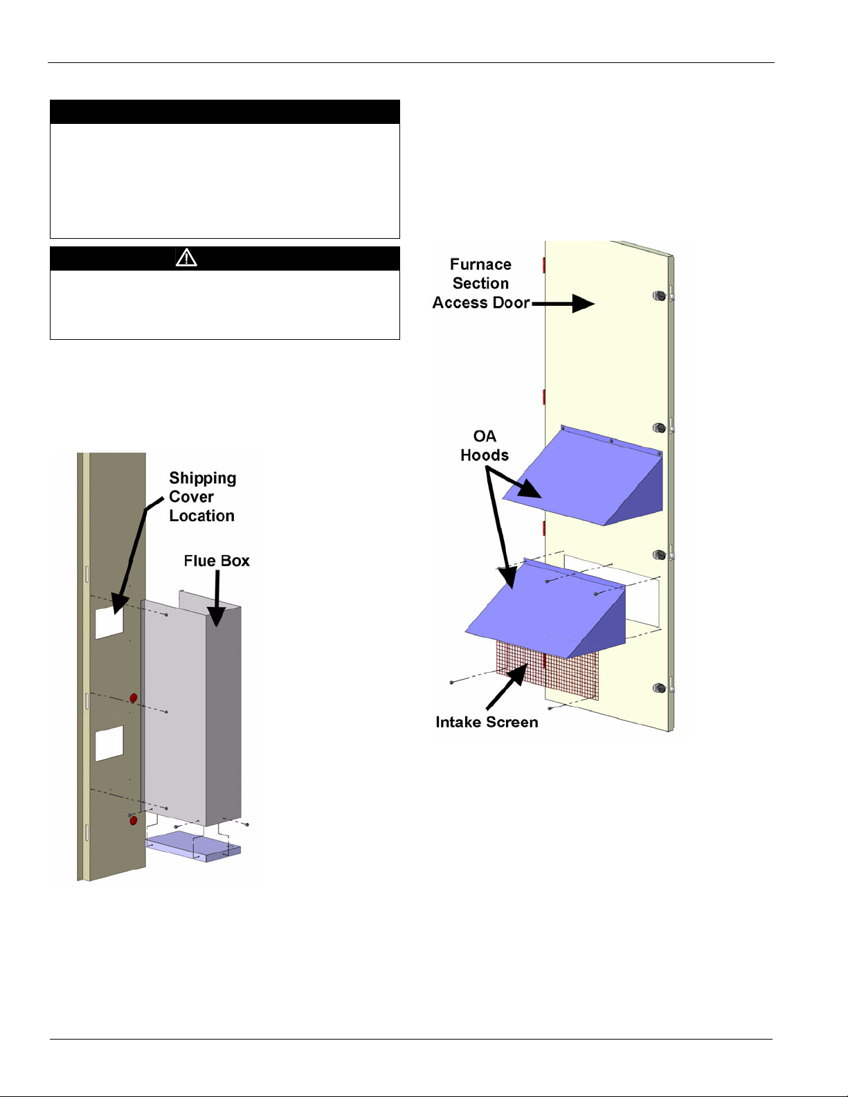
Flue Box
The flue box (Figure 17) is not installed at the factory because
it would increase the width of the unit beyond the allowable
shipping width.
Figure 17: Flue Box Installation
3 Line assembly holes up.
4 Install screws to fasten the flue box to the side of the unit.
Outdoor Air (OA) Hood
The OA hood (Figure 18) is not installed at the factory because
it would increase the width of the unit beyond the allowable
shipping width. The hood is shipped in a box in the fan
section.
Figure 18: Outdoor Air (OA) Hood Installation
The OA hoods must be installed over the outdoor air openings
as shown in Figure 18.
1 Remove and discard the shipping covers.
2 Position the hood over the OA openings.
3 Line assembly holes up.
4 Install screws to fasten the OA hood.
The OA hoods must be installed before the furnace is operated.
The flue box must be installed over the combustion exhaust
openings shown in Figure 17. All holes are prepunched, the
fasteners are furnished and everything is shipped inside the fan
section.
1 Remove and discard the shipping covers.
2 Position the flue box over the exhaust openings.
20 McQuay IM 1058

Optional Gas Heat
Electrical
The McQuay burner receives its electrical power from the
main unit control panel. No additional power wiring must be
routed to the burner. The sequencing of the burner is also
controlled through this panel and therefore is factory wired.
No additional wiring will be required.
DANGER
If you do not follow these instructions exactly, a fire or
explosion may result causing property damage, personal
injury, or loss of life.
A. This appliance does not have a pilot. It is equipped with an
ignition device which automatically lights the burner. Do not try
to light the burner by hand.
B. Before operating, smell all around the appliance area for
gas. Be sure to smell next to the floor because some gas is
heavier than air and will settle on the floor.
WHAT TO DO IF YOU SMELL GAS:
• Do not try to light any appliance.
• Do not touch any electric switch, do not use any phone in
your building.
• Immediately call your gas supplier from a neighbor's
phone. Follow the gas supplier's instructions.
• If you cannot reach your gas supplier, call the fire
department.
C. Use only your hand to push in or turn the gas control knob.
Never use tools. If the knob will not push in or turn by hand,
don't try to repair it, call a qualified service technician. Force or
attempted repair may result in a fire or explosion.
D. Do not use this appliance if any part has been under water.
Immediately call a qualified service technician to inspect the
appliance and to replace any part of the control system and
any gas control which has been under water.
Gas Piping
Gas piping must be sized to provide the minimum required
pressure at the burner when the burner is operating at
maximum input. Consult your local utility on any questions on
gas pressure available, allowing piping pressure drops, and
local piping requirements.
Install all piping in accordance with the National Fuel Gas
Code (ANSI Z223.1), (NFPA 54-1999) and any applicable
local codes.
The proper size piping must be run from the meter to the gas
burner without reductions. Undersized piping will result in
inadequate pressure at the burner. The pressure will be at its
lowest when it is needed the most, at times of maximum
demand. Therefore, it can cause intermittent hard-to-find
problems because the problem may have left before the service
technician has arrived. Avoid the use of bushings wherever
possible.
Remove all burrs and obstructions from pipe. Do not bend
pipe; use elbows or other pipe fittings to properly locate pipe.
A drip leg and a manual shut-off must be installed in the
vertical line before each burner such that it will not freeze.
Install unions so gas train components can be removed for
service. All pipe threads must have a pipe dope which is
resistant to the action of LP gas. After installation, pressurize
the piping as required and test all joints for tightness with a
rich soap solution. Any bubbling is considered a leak and must
be eliminated. Do not use a match or flame to locate leaks.
Gas Pressure Requirements
The pressure furnished to the main gas valve must not exceed
13.9" wc. When the supply pressure is above 13.9" wc, a high
pressure regulator must precede the appliance gas pressure
regulator. The inlet gas pressure must not exceed the
maximum pressure rating of the high pressure regulator, and
the outlet pressure must furnish gas to the appliance pressure
regulator within the pressure range mentioned above.
McQuay IM 1058 21

Optional Gas Heat
Table 10: Capacity of Pipe Natural Gas (CFH)
With Pressure Drop of 0.3" Wc & Specific Gravity Of 0.60
Pipe
Length (ft.)
10 132 278 520 1050 1600 2050 4800 8500 17500
20 92 190 350 730 1100 2100 3300 5900 12000
30 73 152 285 590 890 1650 2700 4700 9700
40 63 130 245 500 760 1450 2300 4100 8300
50 56 115 215 440 670 1270 2000 3600 7400
60 50 105 195 400 610 1150 1850 3250 6800
70 46 96 180 370 560 1050 1700 3000 6200
80 53 90 170 350 530 990 1600 2800 5800
90 40 84 160 320 490 930 1500 2600 5400
100 38 79 150 305 460 870 1400 2500 5100
125 34 72 130 275 410 780 1250 2200 4500
150 31 64 120 250 380 710 1130 2000 4100
175 28 59 110 225 350 650 1050 1850 3800
200 26 55 100 210 320 610 980 1700 3500
NOTE: Use multiplier below for other gravities and pressure drops.
½ ¾ 1 1¼ 1½ 2 2½ 3 4
Pipe Size-inches (Ips)
Table 11: Specific Gravity Other Than 0.60
Specific Gravity Multiplier
0.50 1.100
0.60 1.000
0.70 0.936
0.80 0.867
0.90 0.816
1.00 0.775
PROPANE-AIR
1.10 0.740
PROPANE
1.55 0.622
BUTANE
2.00 0.547
Table 12: Pressure Drop Other Than 0.3"
Pressure Drop Multiplier Pressure Multiplier
0.1 0.577 1.0 1.83
0.2 0.815 2.0 2.58
0.3 1.000 3.0 3.16
0.4 1.16 4.0 3.65
0.6 1.42 6.0 4.47
0.8 1.64 8.0 5.15
Gas Piping Routing Into Unit
On-The-Roof Piping
1 Remove knockout on upright (refer to Figure 19).
2 Route gas supply pipe through hole. Carefully plan pipe
route and fitting locations to avoid interference with
swinging of doors, etc.
Figure 19: Piping Schematic
22 McQuay IM 1058

Optional Gas Heat
Sequence of Operation (Staged Control)
Low Heat Option (2 Stage Control)
The following details the sequence of operation for the low
heat option.
1 Unit DDC control calls for heat.
2 Furnace DDC control module receives a call for heat.
3 High limit switch is checked for safe condition.
4 Proof of airflow switch is check for combustion airflow.
5 60 second prepurge cycle starts.
6 Spark ignitor is activated for 3 seconds.
7 Gas valve receives a command for stage 1 of heat.
8 Burner is ignited.
9 Unit DDC controller calls for stage 2 of heat.
10 Furnace DDC controller receives a stage 2 heat command.
11 Gas valve receives a command for stage 2 of heat.
High Heat Option (4 Stage Control)
For a unit with the optional high heat the above sequence is
followed for the first two stages.
For the remaining 2 stages the above procedure is repeated on
the second furnace module.
Sequence of Operation (Modulating Burner)
Low Heat Option with Modulation
The following details the sequence of operation for the low
heat option.
1 Unit DDC controller calls for heat.
2 Furnace DDC control module receives a call for heat.
3 Furnace safety switches and DDC control are checked for
safe conditions.
4 45 second prepurge cycle starts. Proof of airflow switch is
checked for combustion airflows.
5 Spark ignitor is activated.
6 Gas valve receives a signal to open fully.
7 Burner is ignited and runs for 20 seconds in high fire. Note:
if call for heat is interrupted during this timing, the furnace
will be locked in for the 20 seconds cycle.
8 Gas valve and induction blower motor receives a signal to
modulate burner output to match the unit discharge air
temperature setting.
2 Top Furnace DDC control module receives a call for heat.
3 High limit switch is checked for safe condition.
4 Proof of airflow switch is checked for combustion airflow.
5 45 second prepurge cycle starts.
6 Spark ignitor is activated.
7 Gas valve receives a signal to open fully.
8 Burner is ignited and runs for 30 seconds in high fire
9 Modulating burner gas valve and induction blower motor
receives a signal to modulate burner output to match the
unit discharge air temperature setting.
10 If modulating burner is unable to meet discharge
temperature set point, furnace DDC control calls for third
stage of heating. The top furnace is reduced to low (50%)
fire. The bottom furnace is sequenced on per stage furnaces
sequence of operation (steps 2 - 8).
11 Staged burner gas valve receives a signal to open to 50%.
12 Modulating burner gas valve and induction blower motor
receives a signal to modulate burner output to match the
unit discharge air temperature setting.
13 If stage 3 and modulating furnace is unable to meet
discharge temperature setpoint, furnace DDC controller
calls for stage 4 heat. The bottom furnace will stage up to
high fire and the modulating furnace will reduce to 50%
operation.
14 Staged burner gas valve receives a signal to open fully.
15 Modulating furnace's gas valve and induction blower motor
receives a signal to modulate burner output to match the
unit discharge air temperature setting.
Start-Up Procedures
Start-Up Responsibility
The start-up organization is responsible for determining that
the furnace, as installed and as applied, will operate within the
limits specified on the furnace rating plate.
1 The furnace must not operate at an airflow below the
specified Minimum Airflow CFM (refer to Table 9 on
page 18). On variable air volume systems it must be
determined that the furnace will not be operated if or when
system cfm is reduced below the specified minimum
airflow cfm.
2 It must be established that the gas supply is within the
proper pressure range (refer to Table 9 on page 18).
High Heat Option with Modulation
The following details the sequence of operation for the high
heat option. This option includes dual burners with one being
modulating and the other being 2 stage control.
1 Unit DDC controller calls for heat.
McQuay IM 1058 23

Optional Gas Heat
Start-up and service of this equipment must be performed
by trained and experienced technicians. It is highly
recommended that the initial start-up and future service be
performed by McQuay trained technicians who are familiar
with working on live equipment. A representative of the owner
or the operator of the equipment should be present during startup to receive instructions in the operation, care and adjustment
of the unit.
WARNING
Overheating or failure of the gas supply to shut off can
cause equipment damage, severe personal injury or
death. Turn off the manual gas valve to the appliance before
shutting off the electrical supply.
Before Start-Up
1 Notify inspectors or representatives who may be required
to be present during start-up of gas fuel equipment. These
could include the gas utility company, city gas inspectors,
heating inspectors, etc.
2 Review the equipment and service literature and become
familiar with the location and purpose of the furnace
controls. Determine where the gas and power can be turned
off at the unit and before the unit.
3 Determine that power is connected to the unit and
available.
4 Determine that the gas piping, meter, and service regulator
have been installed, tested, and meet the equipment
requirements.
5 Determine that proper instruments will be available for the
start-up. A proper start-up requires the following:
voltmeter, manometer or gauges with ranges for both
manifold pressure and inlet gas pressure.
Start-Up Preliminary
Close gas main.
1 Check the burner fan wheel for binding, rubbing, or loose
setscrews.
2 Check power.
3 Purge the gas lines.
4 Leak check. Using a rich soap-water mixture and a brush,
check the gas lines for leaks. Correct all leaks before
starting furnace.
24 McQuay IM 1058

Optional Gas Heat
Operating Procedures
DANGER
If you do not follow these instructions exactly, a fire or
explosion may result causing property damage, personal
injury, or loss of life.
A. This appliance does not have a pilot. It is equipped with an
ignition device which automatically lights the burner. Do not try
to light the burner by hand.
B. Before operating, smell all around the appliance area for
gas. Be sure to smell next to the floor because some gas is
heavier than air and will settle on the floor.
WHAT TO DO IF YOU SMELL GAS:
• Do not try to light any appliance.
• Do not touch any electric switch, do not use any phone in
your building.
• Immediately call your gas supplier from a neighbor's
phone. Follow the gas supplier's instructions.
• If you cannot reach your gas supplier, call the fire
department.
C. Use only your hand to push in or turn the gas control knob.
Never use tools. If the knob will not push in or turn by hand,
don't try to repair it, call a qualified service technician. Force or
attempted repair may result in a fire or explosion.
D. Do not use this appliance if any part has been under water.
Immediately call a qualified service technician to inspect the
appliance and to replace any part of the control system and
any gas control which has been under water.
1 Set the thermostat to the lowest setting.
2 Turn off all electric power to the appliance.
3 This appliance is equipped with an ignition device which
automatically lights the burner. Do NOT try to light the
pilot by hand.
4 Open the control access panel.
5 Turn the gas control clockwise to “OFF”.
6 Wait five (5) minutes to clear out any gas. Then, smell for
gas, including near the floor. If you smell gas, STOP!
Follow step “B” in the DANGER label on this page. If you
don't smell gas, proceed to the next step.
7 Turn the gas control counter-clockwise to “ON”.
8 Close the control access panel.
9 Turn on all electric power to the appliance.
10 Set thermostat to desired setting.
11 If the appliance will not operate, refer to “Turning Off Gas
to the Appliance”, and call your service technician or gas
supplier.
Turning Off Gas to the Appliance
1 Set the thermostat to the lowest setting.
2 Turn off all electrical power to the appliance if service is to
be performed.
3 Open the control access panel.
4 Turn the gas control knob clockwise to “OFF”. Do not
force.
5 Close the control access panel.
Service
The furnace DDC controller has diagnostic information for
troubleshooting the furnace operation. The ignition control
module has a LED light that will flash when an abnormal
condition occurs. See Figure 20 for an explanation of the
diagnostic information.
Maintenance
Planned maintenance is the best way to avoid unnecessary
expense and inconvenience. Have this system inspected at
regular intervals by a trained and experienced service
technician. The following service intervals are typical for
average situations but will have to be adjusted to suit your
particular circumstances.
Fuel pressure settings and control settings should be made only
by persons thoroughly experienced with the burner and control
system, and must not be tampered with by persons without
such experience.
Always replace covers on burner controls and boxes as the
electrical contacts are sensitive to dust and dirt. Perform
maintenance of controls, gas valves, and other components in
accordance with instructions contained in the manufacturer's
bulletins.
Monthly
Check air filters and replace if dirty.
Twice Yearly
1 Burner Air - Check burner fan wheel for dirt buildup and
lint. Check combustion air intake louver and flue box for
dirt buildup and accumulation of windborne debris.
2 Cleaning - Inspect flue tubes and combustion chamber,
cleaning as required. Keep burner vestibule clean. Dirt and
debris can result in burner air blockages.
Yearly
Gas Train - Check all valves, piping and connections for
leakage. Inspect and clean flame rod, ignition electrode,
and burner manifold.
Condensate Pan/Drain/P-Trap - Check pan, drain, and ptraps for accumulation of debris. Check that p-traps are
filled with water at the start of each cooling season.
McQuay IM 1058 25

Optional Gas Heat
X
L1 IND
MV
COM
C
2 Stage Gas
Valve
C
HIMV
L1 L2
40VA
BW
Y
BL
Y
Y
BL
Gnd
B
W
W
W
1
B
Gr
B
2
1016-427
Ignition Module
1/4" quick connect termination to harness
HV
Igniter
OR
PS1
PS2
ROS1
APS
ROS2
OR
OR
FS
Flame Sensor
W
R
R
Y
W
1
Y
2
W
BL
Y
Terminal Block
Comb Fan
Motor
24VAC
115VAC
G
APS Airflow Proving Switch
ROS1 Roll Out Switch #1
ROS2 Roll Out Switch #2
from main control panel
Ignition Control Module for Gas Furnace
Figure 20: Typical Staged Gas Furnace Electrical Schematic with Sensor
Ignition Control Module LED Diagnostics
The following LED indicators can be used to diagnose faults
associated with the staged gas furnace.
Table 13: LED Indicator and Fault Conditions
Indicator Fault Condition
Steady Off No power or control hardware fault
Steady On Power applied, control OK
1 Flash Combustion fan motor energized, pressure
2 Flashes Combustion fan motor off, pressure switch
3 Flashes Ignition lockout from too many trials
4 Flashes Ignition lockout from too many flame losses
5 Flashes Control hardware fault detected
switch open
closed
within single call for heat
26 McQuay IM 1058

Optional Gas Heat
1/4" Quick Connec t Termination
Terminal Block
APS Airow Prov ing Sw itch
ROS1 Roll Out Switch #1
ROS2 Roll Out Switch #2
40VA
24VAC
115 VAC
Neutral
Ground
120 VAC
T1 T3
T6
T9
T7
T5
T4
T2
M
Neutral
Hot
Hot
Neutral
Variable
Inducer
Inducer HS I
Flame
Flame Sensor
24V AC
115 VAC
Spark Electrode
W
R
+
-
J4
J8
+
-
J9
J3
ROS1
APS
ROS2
Sensing hose
to fan
-
+
Press u re
Tr ans du cer
J5
Modulating
Gas Valve
24VAC
GND
MOD
RTN
MOD
MV
RTN
MV
Combustion
Board
Limit
Press
Switch
DSI
Board
L1 L2
0-10V DC
0-10V DC
input signal
Comm Port
MJ
Status
LED
WHT
BLK
WHT
BLU
RED
WHT
GRY
ORG
ORG
WHT
BLK
WHT
WHT
BLK
WHT
BLK
GRN
WHT
BLK
Gn d
GRY
RED
BLU
BRN
RED
Ignition Control Module for Modulating Gas Furnace
Figure 21: Typical Modulating Gas Furnace Electrical Schematic with Sensor
McQuay IM 1058 27

Optional Gas Heat
Variable Furnace Controller
McQuay's furnace controller is an electronic device that
delivers full control of the modulating furnace. Control
includes sequencing, ignition, safety, modulation of the control
valve, and the induced draft motor. Inputs to the furnace
control board are an a 0-10V signal. The analog signal will
modulate the burner down to 25% of full load. Safety inputs
include pressure line and electrical connection from the
airflow proofing switch and electrical connection from the
rollout switches. Control board outputs are to the igniter board,
modulating gas valve, and to the induce draft motor.
Ignition Control Module LED Diagnostics
The following LED indicators can be used to diagnose faults
associated with the modulating gas furnace.
Table 14: LED Indicator and Fault Conditions
Indicator Fault Condition
Steady Off No power or control hardware fault
Indicator Fault Condition
Steady On Control fault detected or no 24 VAC power
1 Flash
2 Flashes
3 Flashes
4 Flashes
5 Flashes
6 Flashes Excessive plenum temperature
7 Flashes High limit switch is open or fuse is open
8 Flashes
Slow Flash Normal operation - no call for heat
1 Slow Flash Call for heat
2 Slow Flashes Gas on - call for heat
3 Slow Flashes Gas on - no call for heat
Rapid Flash Retry
Combustion fan motor energized, pressure
switch open
Inducer air pressure reads above zero level
when the inducer is off
Flame is on when is should be off or flame is
off when it should be on
Gas valve is on when is should be off or gas
valve is off when it should be on
Safety relay is on when it should be off or
safety relay is off when it should be on
Pressure switch failed to operate or modulation
current is incorrect
28 McQuay IM 1058

Optional Electric Heat
Electric Heater Design
Optional Electric Heat
If the 8th digit in the model number is an “E”, the rooftop unit
Figure 22: Electric Heat Section
was furnished with a factory installed electric furnace
(Example, MPS035FE). The Maverick commercial rooftop
units are available with low, medium, or high heat output (see
capacities in Table 15). This packaged electric heat rooftop
unit is designed for outdoor non-residential installations only.
The electric heat design consists of a heating coil, DDC
staging control, and all operational safeties. The safety
switches include high-limit temperature switches and
individual coil fusing.
The high limit switch is an automatic reset switch. It opens the
control circuit and shuts the heater down when the temperature
reaches 160°F. The high limit switch closes again allows the
heater to run when the temperature gets to 130°F. There is a
second level of protection with an auxiliary high limit switch.
This switch opens up and shuts the heater down when the
temperature reaches 250°F. The auxiliary switch automatically
resets again at 220°F. The third level of protection is the
secondary auxiliary high limit switch which shut the heater
down at 285°F. This switch requires a manual reset.
Electric Heating Capacity Data
Table 15: MPS 015 – 050 Electric Heating Capacities
Ton s
* Temperature rise is calculated at nominal cfm
Nom
15 6000 4 18 950 61 9.5 36 1900 123 19.0 72 3800 246 38.0
17 6800 4 18 950 61 8.4 36 1900 123 16.7 72 3800 246 33.5
20 8000 4 36 1900 123 14.2 72 3800 246 28.5 90 4740 307 35.5
25 10,000 4 36 1900 123 11 .4 72 3800 246 22.8 90 4740 307 28.4
30 12,000 4 54 2900 184 14.2 72 3800 246 19.0 90 4800 307 23.7
35 14,000 4 54 2900 184 12.2 72 3800 246 16.3 90 4800 307 20.3
40 16,000 4 72 3800 246 14.2 90 4800 307 17.8 108 5700 369 21.3
50 20,000 4 72 3800 246 11 .4 90 4800 307 14.2 108 5700 369 17.1
cfm
Stages
kW
Low Medium High
Min
cfm
MBh Delta T* kW
Min
cfm
MBh Delta T* kW
Min
cfm
MBh Delta T
Electric Heater Data
Table 16: MPS 015 – 050 Electric Heater Data (Maximum Temp. 60°F)
kW Volta ge Amps kW Volta ge Amps
18 208 50 72 208 200
18 230 45 72 230 181
18 460 23
18 575 18 72 575 72
36 208 100
36 230 90 90 230 226
36 460 45
36 575 36 90 575 90
54 208 150
54 230 136 108 575 108
54 460 68
54 575 54
McQuay IM 1058 29
72 460 90
90 208 250
90 460 113
108 460 136

Optional Modulating Hot Gas Reheat
Optional Modulating Hot Gas Reheat
Modulating Hot Gas Reheat
The reheat coil option comes complete with an aluminum
micro channel coil and modulating hot gas valves for leaving
air temperature control.
On a call for dehumidification, the unit will enable the supply
to be over-cooled by the DX coil. Hot gas from the unit
Figure 23: Dual 2-Way Valve Refrigeration Schematic
condenser will be routed to an indoor coil downstream of the
DX coil to reheat the air. Hot gas reheat valves (Figure 23) will
control how much hot gas is routed to the indoor coil to
maintain a discharge air setpoint.
30 McQuay IM 1058

Optional Modulating Hot Gas Reheat
Figure 24: Ideal for Neutral Air Ventilation Control
Dehumidification Initiation
An analog sensor is mounted in the return duct, the space, or
outdoors to sense Relative Humidity. The location is selected
by setting the Sensor Location value on the keypad to Return,
Space, or OAT. OAT can only be selected for units with DAT
control. Dehumidification is disabled when the unit is in either
the Heating or Minimum DAT state. When Dehumidification
is enabled, Dehumidification operation is initiated when
Humidity Control is set to either Relative Humidity or Dew
Point and that value rises above the appropriate setpoint by
more than half its deadband. Economizer operation is disabled
in the Dehumidification mode so the unit immediately
transitions to Cooling if Dehumidification is initiated in
Economizer state.
Dehumidification Termination
Dehumidification is terminated if the selected variable,
Relative Humidity or Dew Point, drops below the appropriate
humidity setpoint by more than half its deadband.
Dehumidification is also terminated if cooling is disabled for
any reason or the unit enters either the Heating or Minimum
DAT state. For units with compressors, the number of cooling
stages is reduced by one and control reverts to normal control
when dehumidification is terminated in the Cooling state.
Another compressor stage change could then occur after one
Cooling Stage Time has elapsed.
Control & Arrangement
In conjunction with dehumidification, MHGRH is used to raise
the temperature of the cooled air to a desirable value. MHGRH
is comprised of a parallel coil arrangement, with both the
condenser and reheat coils of the micro channel type, dual
reheat valves (which operate in concert with one another) and
a check valve. MHGRH components will always be installed
in circuit #2.
During Dehumidification control w/ modulating Hot Gas
Reheat (MHGRH) an analog signal (0-10Vdc) is controlled as
described below.
• A PI Loop is used to control the HGRH valves to maintain
the Discharge Air Temperature from the reheat coil.
• Compressor staging during reheat (or dehumidification) will
be controlled by the Leaving DX Coil Temperature. For
increased dehumidification during reheat, the standard
default compressor staging range is 45 - 52°F.
• When dehumidification is active in the Cooling state, the
reheat set point equals the DAT Cooling Setpoint. For DAT
units, this is the normal DAT set point resulting from any
reset. For Zone Control units, this set point is the result of a
PI Loop based on the Control Temperature.
• Communication with the reheat control valves is
accomplished by providing a 0-10Vdc signal to a pair of
interface boards which in turn supply the control signal to
the reheat valves (step type).
• In the Fan Only state, no sensible cooling is required, but
dehumidification mode will still be enabled if the dew point
or humidity sensor is not satisfied. Reheat set point varies
from a maximum value (default 65°F) when the Control
Temperature is at or below the heating changeover setpoint
to a minimum value (default 55°F) when the Control
Temperature is at or above the cooling changeover setpoint.
• Lead/Lag Arrangement w/ MHGRH (when applicable)
- Alternate staging with circuit #1 as lead will be the stan-
dard default arrangement.
- During cooling mode, circuit #1 will lead and load up
before starting circuit #2.
- During reheat mode, circuit #2 will lead and load up before
starting circuit #1.
- For reheat operation, compressor(s) in circuit #2 must be
active. If the unit is operating in the cooling mode when a
call for dehumidification/reheat arises,circuit #2 will
become the lead and the controller will bring on an additional stage of coolingfor dehumidification. If any compressors in circuit #1 are operating at this moment they
will be switched over to compressors in circuit #2. Dehumidification operation is disabled if circuit #2 is disabled
for any reason.
• In the reheat mode, the minimum position for the reheat
valves is 10% (1.0 Vdc). The controller will modulate the
reheat valves from this starting position.
McQuay IM 1058 31

Optional Modulating Hot Gas Reheat
• Reheat valve(s) must be at 0% (0 Vdc) position before
starting the first compressor in the reheat circuit to prevent
pressure spikes.
• Upon termination of dehumidification (reheat), the
maximum ramp down or decay rate of the reheat control
valves shall be 1% per sec (or 0.1V per sec).
• Upon termination of dehumidification (reheat), staging of
compressor(s) is delayed for 1 minute after reheat capacity =
0% (0 Vdc).
Figure 25: Modulating Hot Gas Reheat Schematic
• Every 24 hours, the reheat control valves will be driven to
their maximum position (10Vdc) and then returned to their
normal operating position (0Vdc). If unit is operating in
cooling or dehumidification (reheat) at the prescribed time it
will be deferred to the next time.
• Dehumidification status can now be found under the MTIII
main system menu. Reheat capacity (valve position) can also
be found under the main system menu, display based on
percentage (0-100%).
32 McQuay IM 1058

Optional Hot Water Heat
Hot Water Heater Design
Optional Hot Water Heat
If the 8th digit of the model number is a “W”, the rooftop unit
was furnished with a factory installed hot water coil (Example:
MPS035FW). The hot water coil comes with a piping
vestibule for field supplied and installed control valve and
piping. The coil is furnished with ODM copper connections.
The Maverick commercial rooftop units are available with a
low heat (one row coil) or a high heat (two row coil)
configuration.
Hot water coils are not recommended for use with entering air
temperatures less than 40°F (4°C). No control system can
guarantee a 100% safeguard against coil freeze up. Glycol
solutions or brines are the only freeze-safe media for operation
of water coils at low entering air temperatures.
Figure 26: Hot Water Heating Schematic
See certified drawings for the recommended piping entrance
locations. Seal all piping penetrations to prevent air and water
leakage.
Note: Factory installed piping is copper. Dissimilar metal
within the plumbing system can cause galvanic
corrosion. To avoid corrosion, provide proper di-electric
fittings as well as appropriate water treatment.
CAUTION
Coil freeze possible. Can damage equipment.
Follow instructions for mixing antifreeze solution. Some
products have higher freeze points in natural state than when
mixed with water. The freezing of coils is not the responsibility
of McQuay International.
McQuay IM 1058 33

Optional Hot Water Heat
Hot Water Pressure Drop Data
Figure 27: MPS 015 – 017 Low and High Heat
Figure 28: MPS 020 – 025 Low and High Heat
34 McQuay IM 1058

Figure 29: MPS 030 – 035 Low and High Heat
Optional Hot Water Heat
Figure 30: MPS 040 – 050 Low and High Heat
McQuay IM 1058 35

Unit Options
Unit Options
Economizer Enthalpy Control
The economizer can be ordered with the optional differential
enthalpy control. With this option a solid-state humidity and
temperature sensing device is located in the return and outdoor
airstreams. These devices are labeled RAE and OAE
respectively. When the outdoor enthalpy is lower than the
return air enthalpy, the economizer operation will be initiated.
If the outdoor air enthalpy is higher than the return air, the
outdoor air damper position will be at the minimum setpoint.
See OM 920 for further information on the economizer
operation.
External Time Clock
You can use an external time clock as an alternative to (or in
addition to) the MicroTech III controller’s internal scheduling
function. The external timing mechanism is set up to open and
close the circuit between field terminals 101 and 102. When
the circuit is open, power is not supplied to binary input ID1.
This is the normal condition where the controller follows the
programmable internal schedule. When the circuit is closed,
power is fed to ID1. The MicroTech III controller responds by
placing the unit in the occupied mode, overriding any set
internal schedule.
Exhaust Fan Option
Economizer units may include exhaust fan options. For units
with CAV applications, the exhaust fans can be ordered as
staged control or they may be ordered with building pressure
control. The building pressure control option has a VFD that
runs the exhaust fan motors and is controlled by the static
pressure sensor number 2 (SPS2). Refer to OM 920 for setting
up the unit controller with these two options. The units are
only available with building pressure control on VAV units.
The exhaust fan motors are permanently lubricated and do not
require any additional periodic lubrication.
Proof-of-Airflow and Dirty Filter Switch
The proof-of-airflow switch (PC7) and the dirty filter switch
(PC5) are supplied on all CAV units. The tubing is installed to
the switches per Figure 31. The proof of airflow switches
senses the pressure difference between the positive pressure in
the supply air fan compartment and the suction pressure on the
leaving air side of the filters. The differential pressure is
factory set at 0.25" for this switch. The dirty filter switch
senses the pressure difference across the filter; from the
entering air side of the filter to the leaving air side of the
filters. The switch is factory set at 1.0". When the pressure
difference across the filters is sensed at this value, the dirty
filter alarm will appear on the DDC controller.
Figure 31: Pressure Tubing Diagram
TO ENTERING
AIR SIDE OF
THE FILTERS
TO LEAVING
AIR SIDE OF
THE FILTERS
TO SUPPLY
FAN PLENUM
PC5
HI LO
HI
LO
PC7
HI
LO
DHL
All VAV units also have the PC7 and PC5 switches as standard
(see Figure 31). These switches are tied into the Duct High
Limit switch (DHL) as shown in Figure 31.
The DHL is factory set at 4.0". When this differential pressure
is sensed the normally closed contacts will open on the switch
giving the DHL alarm at the unit controller.
Duct High Pressure Limit
The duct high pressure limit control (DHL) is provided on all
VAV units. The DHL protects the duct work, terminal boxes,
and the unit from over pressurization, which could be caused
by, for example, tripped fire dampers or control failure.
The DHL control opens when the discharge plenum pressure
rises to 3.5" wc (872 Pa). This setting should be correct for
most applications and should not be adjusted.
If the DHL switch opens, digital input ID9 on the Unit Control
Board will be de-energized. The MicroTech III controller then
shuts down the unit and enters the Off-Alarm state. The alarm
must be manually cleared before the unit can start again. Refer
to the operation manual supplied with your unit for more
information on clearing alarms (refer to OM 920).
36 McQuay IM 1058

Unit Options
460V LINE460V LINE
VOLTAGE PRI.VOLTAGE PRI.
Convenience Receptacle (Field Powered)
A Ground Fault Circuit Interrupter (GFCI) convenience
receptacle is provided in the main control box on all units. To
use this receptacle, connect a separate field-supplied 115 V
power wiring circuit to the outlet.
Figure 32: Unit Powered GFCI Receptacle Schematic
Convenience Receptacle (Unit Powered)
A Ground Fault Circuit Interrupter (GFCI) convenience
receptacle is provided in the main control box on all units. The
receptacle shall be powered by a factory installed and wired
120V, 20 amp power supply. The power supply shall be wired
to the line side of the unit's main disconnect, so the receptacle
is powered when the main unit disconnect is off. This option
shall include a GFI receptacle, transformer, and a branch
circuit disconnect. The electrical circuit shall be complete with
primary and secondary overload protection. See Figure 32 for
a branch circuit diagram.
McQuay IM 1058 37

Wiring Diagrams
Wiring Diagrams
Figure 33: VAV Power
38 McQuay IM 1058

Wiring Diagrams
McQuay IM 1058 39

Wiring Diagrams
Figure 34: VAV Control—Inputs
40 McQuay IM 1058

Wiring Diagrams
McQuay IM 1058 41

Wiring Diagrams
Figure 35: VAV Control—Outputs (Staged Gas Heat)
42 McQuay IM 1058

Wiring Diagrams
McQuay IM 1058 43

Wiring Diagrams
Figure 36: CAV Power
44 McQuay IM 1058

Wiring Diagrams
McQuay IM 1058 45

Wiring Diagrams
Figure 37: CAV Control—Inputs
46 McQuay IM 1058

Wiring Diagrams
McQuay IM 1058 47

Wiring Diagrams
Figure 38: CAV Control—Outputs (Staged Gas Heat)
Figure 39: VAV/CAV Control—Outputs (Modulating Gas Heat)
48 McQuay IM 1058

Figure 40: Electric Heat Option Power
Figure 41: Electric Heat Option—Outputs
Wiring Diagrams
McQuay IM 1058 49

Sequence of Operation
Any Othe r Stat e
Fan Only
Minimum DAT
r
Mechanical
Coolling
Start Up
Recirculation
Sequence of Operation
Operating States
The transition from any operating state to another is
graphically represented in Figure 42.
Figure 42: State Diagram
Off
Economize
Heating
Fan Only
The outside air damper will modulate to the minimum position
and based upon the sensor inputs, the unit will go into one of
the four running states - “Heating,” “Cooling,”
“Economizing,” or “Minimum DAT.” If the control
temperature is between its setpoint and its dead band, the unit
will remain in the “Fan Only” state.
Heating
The unit's heating mode of operation is controlled by the
control temperature and the heating setpoint temperature. The
unit goes into the heating mode of operation by analyzing the
control temperature.
The control temperature can be either the return temperature or
the space temperature.
The return temperature is typically used for VAV units and the
space temperature is typically used for CAV units.
The unit goes into the heating mode of operation when the
control temperature (return or space temperature) is below the
heating setpoint by more than ½ the deadband.
Example - If the heating setpoint is 68.0°F and the deadband is
1.0°F, the unit will not go into the heating mode of operation
until the control temperature reaches 67.4°F.
Start Up
With a “start up” command from the “Off” State the unit will
default into the “Start Up” state of operation for 3 minutes.
During this time, the fan is off.
Recirculation
Next, the unit will transition into the “Recirculation” state of
operation for another 3 minutes. During this time, the outside
air damper will close and the fan will turn on, thereby mixing
the air in the ductwork and the space.
When this takes place, the heating mode of operation will
begin and the 1st stage of heating operation will start.
The next stage, up or down, will take place after 4 minutes.
This “4 minutes” is called the stage timer. The gas or electric
heat module will continue to stage up as long as the control
temperature is below the heating setpoint by more than ½ the
heating setpoint deadband. The unit will stage down if the
maximum discharge air temperature of 120°F is reached. Gas
units with one gas valve have 2 stages of heating and units
with two gas valves have 4 stages of heating.
Minimum DAT
This control mode is designed to temper the air in the
ductwork when in heating mode. When the unit is in the “Fan
Only” state and the Discharge Air Temperature is less than the
minimum discharge air temperature limit, “Minimum DAT”
control is initiated. The unit will turn on minimum heat until
the discharge air temperature exceeds the limit.
50 McQuay IM 1058

Sequence of Operation
Mechanical Cooling
Constant Volume (Space Comfort Controller)
The control temperature for a CAV unit is typically the space
temperature. A space temperature sensor must be field
installed into the occupied space and connected to the unit
controller.
The unit goes into the cooling mode of operation when the
control temperature (space temperature) is above the cooling
setpoint by more than ½ the deadband.
Example - the cooling setpoint is set to 70.0°F and the
deadband is 1.0°F, the unit will not go into the cooling mode of
operation until the space sensor reaches 70.6°F.
When this takes place, the cooling mode of operation will
begin and the 1st stage of compressor operation will start.
The unit controller will turn on the next stage of compressor
operation, or turn off a stage of compressor operation, to
maintain the cooling setpoint temperature within the deadband.
When a compressor stage turns on, the next compressor stage,
up or down, will not take place for the next 4 minutes. This “4
minutes” is called the stage time. Reference the “Cooling
Setup” menu for the adjustable stage time value.
When a cooling stage is initiated no further operation will take
place within the stage timer limit. In the above example, the
unit will stage down or turn off the cooling mode of operation
when the cooling setpoint reaches 69.4°F.
Variable Air Volume (Discharge Air Controller)
The unit's cooling mode of operation is controlled by the
control temperature, the change-over temperature, and the
discharge air temperature. The unit goes into the cooling mode
of operation by analyzing the control temperature. The control
temperature for a VAV system is the return temperature.
The unit goes into the cooling mode of operation when the
control temperature (return temperature) is above the changeover setpoint by more than ½ the deadband.
Example - If the change over temperature is 70.0°F and the
deadband is 1.0°F, the unit will not go into the cooling mode of
operation until the return temperature reaches 70.6°F.
When this takes place, the cooling mode of operation will
begin and the 1st stage of compressor operation will start.
The unit controller will turn on the next stage of compressor
operation, or turn off a stage of compressor operation, to
maintain the discharge air temperature setpoint within the
deadband. When a compressor stage turns on, the next
compressor stage up or down will not take place for the next 4
minutes. This “4 minutes” is called the stage timer.
When a cooling stage is initiated no further operation will take
place within the stage timer limit. Reference the Cooling Setup
menu for the adjustable stage time value. In the above
example, the unit will stage down or turn off the cooling mode
of operation when the return temperature reaches 69.4°F.
Economizer
When the economizer is enabled, the outside air temperature is
below the changeover setpoint, and the differential enthalpy
switch (if installed) is made, the economizer becomes the first
stage of cooling. It will modulate to control to either the
discharge air temperature (VAV) or space temperature (CV).
Every 4 minutes, the unit can then either add mechanical
cooling if the economizer is at 100% open, continue
economizing, or if the control temperature is satisfied, return
to minimum position and transition back to “Fan Only” mode.
If the enthalpy switch breaks or the outside air warms, the unit
will exit economizing and continue to mechanically cool while
returning to the minimum position for ventilation.
McQuay IM 1058 51

Check, Test, and Start Procedures
Check, Test, and Start Procedures
Pre-Start of Unit
All units are completely run tested at the factory to promote
proper operation in the field. However, to ensure proper
operation once the unit is installed, the following check, test,
and start procedures must be performed to properly start the
unit. To obtain full warranty coverage, complete and sign the
check, test, and start form supplied with the unit and return it
to McQuay International.
WARNING
Electric shock and moving machinery hazard. Can cause
severe equipment damage, personal injury, or death.
Disconnect and tag out all electrical power before servicing this
equipment.
All start-up and service work must be performed only by trained,
experienced technicians familiar with the hazards of working on
this type of equipment.
Read and follow this manual: “MicroTech III Unit Controller”
(OM 920) before operating or servicing.
Bond the equipment frame to the building electrical ground
through grounding terminal or other approved means.
A representative of the owner or the operator of the equipment
should be present during start-up to receive instructions in the
operation, care, and maintenance of the unit.
Servicing Control Panel Components
WARNING
Hazardous voltage. May cause severe injury or death.
Disconnect electric power before servicing equipment.
Before Start-Up
1 Remove shipping bolt form fan spring.
2 Verify that the unit is completely and properly installed
with ductwork connected.
3 Verify that all construction debris is removed, and that the
filters are clean.
4 Verify that all electrical work is complete and properly
terminated.
5 Verify that all electrical connections in the unit control
panel are tight, and that the proper voltage is connected.
6 Verify all nameplate electrical data is compatible with the
power supply.
7 Verify the phase voltage imbalance is no greater than 2%.
8 Verify that gas piping is complete and leak tight.
9 Verify that the shutoff cock is installed ahead of the
furnace, and that all air has been bled from the gas lines.
10 Verify installation of gas flue and outside air vents.
11 Manually rotate all fans and verify that they rotate freely.
12 Verify that the belts are tight and the sheaves are aligned.
13 Verify that all setscrews and fasteners on the fan assemblies
are still tight. “See “Setscrews” on page 59.”
14 Verify that the evaporator condensate drain is trapped and
that the drain pan is level.
15 If unit is curb mounted, verify that the curb is properly
flashed to prevent water leakage.
16 Review the equipment and service literature, the sequences
of operation, and the wiring diagrams to become familiar
with the functions and purposes of the controls and devices.
17 Determine which optional controls are included with the
unit.
Power-Up
1 Close the unit disconnect switch.
2 Power should now be supplied to the control panel.
Fan Start-Up
1 Remove shipping bolt from fan spring if this has not
already been done.
1 Verify fan spring adjustment and that the fan assembly is
level. Adjust as necessary.
2 Verify all duct isolation dampers are open.
3 Place the unit into the “Fan Only” mode through the
keypad.
4 The controller should enter the “Startup Initial” operating
state. If the fan does not run, check the manual motor
protectors or that the circuit breakers have not tripped.
5 Verify the rotation is correct.
Economizer Start-Up
1 Check whether the outdoor air is suitable for free cooling.
2 At the keypad, set the cooling setpoint low enough so the
controller calls for cooling.
3 Place the unit into cooling mode through the keypad menu.
4 Observe the outdoor air dampers:
a If the outdoor enthalpy is low, the control algorithm
should start to modulate the dampers open to maintain
the discharge air setpoint.
b If the outdoor enthalpy is high, the dampers should
maintain their minimum position.
Note: It may not be possible to check the economizer
operation in both low and high enthalpy states on the
same day. If this is the case, repeat this procedure on
another day when the opposite outdoor air enthalpy
conditions exist.
52 McQuay IM 1058

Compressor Start-Up
1.21"
Fan Blade
Orifice
With the supply fan operational, prepare for compressor
operation.
CAUTION
Low ambient temperature hazard. Can cause compressor
damage. Do not attempt to start up and check out the
refrigeration system when the outdoor air temperature is below
20°F.
1 Connect service gauges and verify that the unit has not lost
its refrigerant charge.
2 Verify that the crankcase heaters are operating. These
should operate for at least 24 hours before starting the
compressors.
3 Verify that the condenser fan blades are positioned properly
(see Figure 43) and that the screws are tight. The fan blade
must be correctly positioned within its orifice for proper
airflow across the condenser coils.
4 Check the fan rotation.
Figure 43: Condenser Fan Blade Positioning
Scroll Compressor Rotational Direction
Scroll compressors only compress in one rotational direction.
Three-phase compressors rotate in either direction depending
upon phasing of the power to L1, L2, and L3. Since there is a
50/50 chance of connecting power to cause rotation in the
reverse direction, verify that the compressor rotates in the
proper direction after the system is installed. If the compressor
is rotating properly, suction pressure drops and discharge
pressure rises when the compressor is energized. If the
compressor is rotating in reverse, the sound level is louder and
current draw is reduced substantially. After several minutes of
operation, the compressor’s internal protector trips.
All three-phase compressors are wired the same internally.
Therefore, once the correct phasing is determined for a specific
system or installation, connecting properly phased power leads
to the same terminals should maintain proper rotation
direction.
Perform the Following Procedure:
1
At the keypad, set the cooling setpoint low enough so that
the controller will call for cooling.
Check, Test, and Start Procedures
NOTICE
Venting refrigerant to atmosphere is not allowed per most
local laws and/or codes.
2 Verify that compressor #1 starts. If the compressor motor
hums but does not run, verify that it is getting three-phase
power.
3 The compressor should operate continuously while there is
a call for cooling. If the compressor cycles on and off on its
low pressure switch, perform the following:
a Verify that the circuit is not short of refrigerant.
b Check for low airflow across the evaporator coil.
c Check for clogged filters.
d Check for restricted ductwork.
e Check for very low temperature return air entering the
unit.
f Verify that the liquid line components, expansion valve,
and distributor tubes are feeding the evaporator coil.
g Verify that all air handling section panels are closed.
4 Verify that the condenser fans are cycling and rotating
properly (blowing air upward). When the compressor
starts, at least one condenser fan should also start.
5 Check the oil level in the compressor sightglass. If low oil
is observed, it is possible that liquid refrigerant is returning
to the compressor. Check the suction superheat, see
“Expansion Valve Superheat Adjustment” below. It should
be between 10°F (5.5°C) and 13°F (7.2°C). See “Expansion
Valve Superheat Adjustment” below.
6 Verify that the condenser refrigerant subcooling at full
capacity is between 13°F and 20°F.
Checking Subcooling
Following are recommendations for checking subcooling:
1 Run unit until it reaches steady state. Close the unit section
doors. Running the unit with its doors open will affect
system operation.
2 Measure the discharge gas pressure at the compressor
discharge gauge port with an accurate gauge. Use this
pressure to determine the saturation temperature of the
refrigerant.
3 Measure liquid temperature accurately by attaching a
thermocouple to the liquid line tube leaving the condenser
coil. Insulate the tube and thermocouple for more accurate
results.
4 Subtract the measured liquid temperature from the
saturation temperature to determine the subcooling.
5 As a general rule, high subcooling indicates that the circuit
is low on charge. Low subcooling generally indicates that
the circuit has too much charge.
McQuay IM 1058 53

Check, Test, and Start Procedures
Bearing
Motor
Must be
parallel
Fixed Pitch
Sheave
Center lines
must coincide
Must be
parallel
Expansion Valve Superheat Adjustment
It is very important that the expansion valve superheat setting
be adjusted to be between 10°F (5.5°C) and 13°F (7.2°C).
Insufficient superheat will cause liquid floodback to the
compressor which may result in slugging. Excessive superheat
will reduce system capacity and shorten compressor life.
Turn the adjustment stem clockwise to increase superheat. Not
exceeding one turn, adjust the stem and then observe the
superheat. Allow up to 30 minutes for the system to rebalance
at the final superheat setting.
Checking Superheat
Following are recommendations for checking superheat:
1 Close the unit section doors. Running the unit with its
doors open will affect expansion valve and system
operation considerably.
2 Check the pressure and temperature at the suction gauge
port.
Sheave Alignment
1 Verify both motor and fan sheaves are in alignment and the
shafts are parallel. The center line of the motor sheave must
be in line with the center line of the fan sheave. See
Figure 44.
2 Verify that all setscrews are torqued to the values shown in
Table 18 on page 59 before starting drive. Check setscrew
torque and belt tension after 24 hours of service.
Figure 44: Sheave Alignment (Adjustable Shown)
Drive Belt Tension Adjustment
1 The ideal tension is the lowest tension at which the belt will
not slip under peak load conditions. Over tensioning
shortens belt and bearing life.
2 Check tension frequently during the first 24–48 hours of
operation.
3 Keep belts free from foreign material which may cause
slippage.
4 Make V-drive inspection on a periodic basis. Adjust tension
if the belt is slipping. Do not apply belt dressing. This may
damage the belt and cause early failure.
Air Balancing
The following should be performed by a qualified air
balancing technician:
WARNING
Moving machinery hazard. Can cause severe personal
injury or death. Do not use a mechanically driven tachometer
to measure the speed of return fans on this fan arrangement.
Use a strobe tachometer.
1 Check the operating balance with the economizer dampers
positioned for both full outdoor air and minimum outdoor air.
2 Verify that the total airflow will never be less than that
required for operation of the electric heaters or gas furnace.
3 When the final drive adjustments or changes are complete,
check the current draw of the supply fan motors. The
amperage must not exceed the service factor stamped on
the motor nameplate.
WARNING
Rotating parts can cause severe personal injury or death.
Replace all belt/fan guards that are removed for service.
54 McQuay IM 1058

Final Control Settings
Controller Settings for Normal Operation
When all start-up procedures are completed, set the controls
and program the MicroTech III controller for normal
operation. Use the following list as a guide; some items may
not apply to your unit.
1 Set the heating and cooling parameters as required for
normal unit operation:
a Temperature \ Zone Cooling \
b Temperature \ Zone Heating \
c Temperature \ Discharge Cooling \
2 Set the low ambient compressor lockout setpoint as
required. Do not set it below 20°F.
3 Set the high ambient heat lockout temperature setpoint.
4 Set the alarm limits as required.
5 Set the duct static pressure control parameters as required.
Final Control Settings
6 Set the building static pressure control parameters as
required.
7 Set the economizer control parameters as required.
8 Set the date and time in keypad menu.
9 Set the operating schedule as required using keypad menus.
Note: Unit operation may also be controlled by the building
automation system.
Maintaining Control Parameter Records
McQuay recommends that the MicroTech III controller’s
setpoints and parameters be recorded and saved for future
reference. If the microprocessor control board requires
replacement, this record facilitates entering the unit’s proper
data.
McQuay IM 1058 55

Maintenance
Maintenance
Performing Service Maintenance
Installation and maintenance must be performed only by
qualified personnel who are experienced with this type of
equipment and familiar with local codes and regulations.
WARNING
Moving machinery and electrical power hazards. May
cause severe personal injury or death. Disconnect and lock
off all power before servicing equipment.
CAUTION
Sharp edges are inherent to sheet metal parts, screws,
clips, and similar items. May cause personal injury.
Exercise caution when servicing equipment.
Servicing Control Panel Components
Disconnect all electric power to the unit when servicing
control panel components. Before servicing, always inspect
units for multiple disconnects to ensure all power is removed
from the control panel and its components.
WARNING
Hazardous voltage. May cause severe injury or death.
Disconnect electric power before servicing equipment. More
than one disconnect may be required to de-energize the unit.
• Check the power and control voltages.
• Check the running amperage of all motors.
• Check all operating temperatures and pressures.
• Check and adjust all temperature and pressure controls as
needed.
• Check and adjust all damper linkages as needed.
• Check the operation of all safety controls.
• Check the condenser fans and tighten their setscrews.
All-Aluminum Condenser Coils
The condenser coils are an all-aluminum design including the
connections, micro-channels, fins (an oven brazing process
brazes the fins to the micro-channel flat tube), and headers
(Figure 45), which eliminates the possibility of corrosion
normally found between dissimilar metals of standard coils.
During the condensing process, refrigerant in the coil passes
through the micro-channel flat tubes, resulting in higher
efficiency heat transfer from the refrigerant to the airstream.
Figure 45: Micro-Channel Coil Cross-Section
Planned Maintenance
Preventive maintenance is the best way to avoid unnecessary
expense and inconvenience. Have this system inspected at
regular intervals by a qualified service technician. The
required frequency of inspections depends upon the total
operating time and the indoor and outdoor environmental
conditions. Routine maintenance should cover the following
items:
• Tighten all belts, wire connections, and setscrews.
• Clean the evaporator and condenser coils mechanically or
with cold water, if necessary. Usually any fouling is only
matted on the entering air face of the coil and can be
removed by brushing or vacuuming.
• Lubricate the motor and fan shaft bearings.
• Align or replace the belts as required.
• Clean or replace the filters as required.
Note: A partially full sight glass is not uncommon at part load
conditions. A varying amount of bubbles may be
noticeable in the sightglass, which is normal.
• Check for proper superheat.
• Check for blockage of the condensate drain. Clean the
condensate pan as needed.
56 McQuay IM 1058

Maintenance
Connecting the Condenser Coil to Copper Tubing
Figure 46 shows the aluminum condenser coil connection to
the copper tubing in the unit. Because of the low melting point
of aluminum (1220°F compared to 1984°F for copper), this
brazed joint is performed with a low temperature brazing
process.
CAUTION
Potential equipment damage. If a standard copper brazing
process is performed at this joint, the process will damage
the aluminum connection. If a condenser coil ever needs to
be replaced, the copper aluminum joint repair should be done
with a ProBraze™ repair kit manufactured by Omni
Technologies Corporation. A non-corrosive flux must also be
used. The brazing temperature should be between 850°F –
900°F.
Figure 46: Aluminum/Copper Connection
• Provide proper drainage around the unit to prevent flooding
of the equipment.
• Provide adequate protection from vandalism, mechanical
contact, etc.
• Make sure all doors are securely closed and all latches
closed.
• Units should be fitted with covers over the supply and return
air openings.
Preparation for Storage
Supply Fans
1 Remove the drive belts, tag them with the fan name and
unit serial number, and store them in a conditioned space
out of direct sunlight.
2 Once every two weeks, rotate the fan and motor shafts.
Mark the shaft positions first to make sure they stop in a
different position.
3 Depending on local climate conditions, condensate may
collect on components inside the units. To prevent surface
rust and discoloration, spray all bare metal parts with a rust
preventive compound. Pay close attention to fan shafts,
sheaves, bearings, and bearing supports.
Unit Storage
Location
The Maverick II is an outdoor unit. However, the construction
schedule may dictate storage either on the ground or in its final
position at the site. If the unit is stored on the ground,
additional precautions should be taken as follows:
• Make sure that the unit is well supported along the length of
the base rail.
• Make sure that the unit is level (no twists or uneven ground
surface).
Cabinet Sections
Once a month, open a door on each section and verify that no
moisture or debris is accumulating in the unit.
Control Compartment
1 McQuay International recommends that the electronic
control equipment in the unit be stored in a 5% to 95% RH
(non-condensing) environment.
2 It may be necessary to put a heat source (light bulb) in the
main control panel to prevent the accumulation of
atmospheric condensate within the panel. The location and
wattage of the heat source is dependent on local
environmental conditions.
3 Check the control compartment every two weeks to
confirm that the heat source is functional and is adequate
for current conditions.
Restart
After extended storage, perform a complete start up. Inevitable
accumulations of dirt, insect nests, etc. can contribute to
problems if not cleaned out thoroughly prior to start up. In
addition, thermal cycling tends to loosen mechanical and
electrical connections. Following the startup procedure helps
discover these and other issues that may have developed
during the storage interval.
McQuay IM 1058 57

Maintenance
Bearing Lubrication
CAUTION
Bearing overheating potential. Can damage the equipment.
Do not overlubricate bearings. Use only a high grade mineral
grease with a 200°F safe operating temperature.
Motor Bearings
Supply Fans
Supply fan motors should have grease added after every 2000
hours of operation. Use one of the greases shown in Table 17.
Using the following procedure, relubricate the bearings while
the motor is warm, but not running.
1 Remove and clean upper and lower grease plugs.
2 Insert a grease fitting into the upper hole and add a small
amount of clean grease with a low pressure gun.
3 Install the lower grease plug.
4 Run the motor for five minutes before installing the upper
grease plug.
Condenser Fan and Exhaust Fan
The condenser fan and exhaust fan motors are permanently
lubricated and require no periodic lubrication.
Fan Shaft Bearings
Relubricate fan shaft bearings periodically. Relubricate
according to the schedule on the fan housing. If the bearings
are exposed to wet conditions, wide temperature variations, or
other severe atmospheric conditions, relubricate more
frequently. Use one of the greases shown in Table 17.
Table 17: Recommended Greases
Manufacturer Product Name Tem p. Ra nge (° F)
Texaco Lubricants Co. Premium RB -30 to 300
Mobil Oil Corporation Mobilith AW2 -40 to 325
Shell Oil Company Alvania No. 2 -20 to 240
Vibration Levels
Each unit as shipped is trim balanced to operate smoothly. To
provide satisfactory operation after shipping and installation,
use accepted industry guidelines for field balancing fans.
Note: Excessive vibration from any cause contributes to
premature fan and motor bearing failure. Monitor
overall vibration levels every six months of operation.
An increase in levels is an indication of potential
trouble.
Vibration Causes
1 Wheel imbalance.
a Dirt or debris on wheel blades.
b Loose setscrews in wheel hub or bearing-to-shaft.
c Wheel distorted from overspeed.
2 Bent shaft.
3 Faulty drive.
a Bad V-belts; lumpy, or mismatched.
b Belt tension too tight or too loose.
4 Bad bearings or loose bearing hold-down bolts.
5 Motor imbalance.
6 Fan section not supported evenly on foundation.
While the bearing is at normal operating temperatures, rotate
the fan by hand and add only enough grease to purge the seals.
The seals bleed slightly when this occurs. Do not overlubricate.
Periodic Service and Maintenance
1 Check all moving parts for wear every six months.
2 Check bearing collar, sheave, and wheel hub setscrews,
sheave capscrews, and bearing hold-down bolts for
tightness every six months.
58 McQuay IM 1058

Maintenance
W h e e l
F u n n e l
A
Setscrews
Setscrews are used to lock bearings, sheaves, locking collars,
and fan wheels to their shafts. They must be checked
periodically to see that they have not loosened. If this is not
done, severe equipment damage could occur.
Refer to the values in Table 18 and check the tightness of all
setscrews with a torque wrench.
Table 18: Setscrew Minimum Torque Specifications
Setscrew Diameter (in.) Minimum Torque (ft.lb)
1/4 5.5
5/16 10.5
3/8 19.0
7/16 29.0
1/2 42.0
5/8 92.0
Supply Fan Wheel-to-Funnel Alignment
The fan wheel-to-funnel alignment must be as shown in
Figure 47 to obtain proper air delivery and operating
clearance. If necessary, adjustments are made as follows:
1 Verify that the fan shaft has not moved in its bearings.
2 Loosen the fan hub setscrews and move the wheel(s) along
the shaft as necessary to obtain the correct dimension
shown in Table 19.
3 Retighten the setscrews to the torque specification given in
Table 18 on page 59. Tighten the setscrews over the
keyway first; tighten those at 90 degrees to the keyway last.
4 Verify that the radial clearance around the fan is uniform.
Figure 47: SWSI Airfoil Wheel-to-Funnel Alignment
Refrigerant Charge
The unit nameplate references proper charge for each
refrigerant circuit in case a full charge must be added to the
unit.
CAUTION
Severe loss of charge may occur if the high refrigerant
pressure switch is replaced before reclaiming the
refrigerant. Replace pressure switch after reclaiming
refrigerant.
Servicing Refrigerant Sensors or Switches
The Maverick II includes the following refrigerant sensors or
switches.
1 Low refrigerant pressure sensing, operating switch,
automatic reset.
a Disables associated compressors on a drop in suction
pressure to approximately 35 psig.
b Enables associated compressors on a rise in suction
pressure to approximately 60 psig.
2 High refrigerant pressure, protective switch, manual reset
at keypad.
The low pressure switch senses refrigerant pressure through
shrader fittings that contain cores. The cores are stop valves
that do not allow refrigerant to flow through the Shrader unless
the device is in place. Therefore, the low pressure switch can
be replaced without reclaiming the refrigerant.
The Shrader that serves the high pressure switch does not
contain a core in order to maximize the functionality of the
safety. Therefore it cannot be replaced unless the
refrigerant has already been reclaimed.
Servicing Optional Electric Heater
WARNING
Hazardous voltage. May cause severe injury or death.
Disconnect electric power before servicing equipment. More
than one disconnect may be required to de-energize the unit.
Table 19: SWSI Airfoil Wheel-to-Funnel Relationship
Wheel-to-Funnel Relationship (in inches)
Wheel Diameter A
15 0.44
18 0.44
20 0.44
22 0.44
24 0.44
30 0.56
McQuay IM 1058 59
If the electric heater is not operating properly, a qualified
electrician should perform the following to check if the heater
is damaged:
1 Measure continuity through all fuses.
2 Check that all electrical connections are tight. Look for
signs of arcing.
3 Check the resistance to ground for each circuit. It should be
infinite.
4 Check the resistance phase to phase for each circuit.
5 Check all contactors.

Service and Warranty Procedure
Service and Warranty Proc edure
Replacement Parts
When contacting McQuay for service or replacement parts,
provide the model number, serial number, and unit part
number of the unit as stamped on the serial plate attached to
the unit. For questions regarding wiring diagrams, provide the
number on the specific diagram. If replacement parts are
required, include the date of unit installation, the date of
failure, an explanation of the malfunction, and a description of
the replacement parts required.
Scroll Compressor
All McQuay Rooftop products include a first-year parts only
warranty. The warranty period extends 12 months from startup
or 18 months from date of shipment, whichever comes first.
Labor to install these parts is not included with this warranty.
Compressors are considered a part and are included in this
standard warranty.
All Compressors
Replacement compressors for McQuay Rooftop Units can be
obtained from the McQuay Service Parts department.
The decision to replace the failed portion of the compressor
tandem, as opposed to replacing the entire tandem, must be
decided based on the following.
1 In warranty: Warranty only covers replacement of the failed
portion of the tandem.
2 Out of warranty: The customer decides whether to replace
the entire tandem or just a portion.
3 Some equipment may include the extended 2nd - 5th year
compressor warranty option.
Order the replacement compressor through the McQuay Parts
Department (Minneapolis).
1 Contact the McQuay Parts Department for compressor
availability.
2 Send a completed parts order form to the McQuay Parts
Department.
3 The Parts Department processes the order and the
compressors are shipped from our Dayton, OH warehouse
via ground transportation. If next-day air is required,
indicate this on the parts order form and a freight charge
will be billed to your account. Air freight costs are not
covered under the McQuay warranty.
4 After the failed compressor is replaced, return it to McQuay
International with a Return Goods Tag attached, which you
will receive in the mail. It must be attached to the
compressor. The Return Goods Tag has instructions on
where to send the compressor. If the compressor is not
returned, you will be billed for the replacement compressor.
5 Consideration may be given at this time to a compressor
teardown analysis, depending on the history of failures.
In-Warranty Return Material Procedure
Material other than compressors may not be returned except by
permission of authorized factory service personnel of McQuay
International at Minneapolis, Minnesota.
A “return goods” tag will be sent to be included with the
returned material. Enter the information as called for on the tag
in order to expedite handling at out factories and issuance of
credits. All parts shall be returned to the factory designated on
the return goods tag, transportation charges prepaid.
The return of the part does not constitute an order for
replacement. A purchase order for the replacement part must
be entered through your nearest McQuay representative. The
order should include the component's part number and
description and the model and serial numbers of the unit
involved.
If it is determined that the failure of the returned part is due to
faulty material or workmanship within the standard warranty
period, credit will be issued on the customer's purchase order.
60 McQuay IM 1058

Commercial Rooftop Equipment Warranty Registration Form
Commercial Rooftop Equipment Warranty
Commercial Rooftop Equipment Warranty
Registration Form
To comply with the terms of McQuay Warranty, complete and return this form within
10 days to McQuay, Warranty Department
Check, test, and start procedure for Maverick II roof mounted air conditioners.
Job Name:
Installation address: __________________________________________________________________________________________________
City: _____________________________________________________________________________ State:___________________________
Purchasing contractor: ________________________________________________________________________________________________
City:______________________________________________________________________________ State:___________________________
Name of person doing start-up (print) ____________________________________________________________________________________
Company name _____________________________________________________________________________________
Address ___________________________________________________________________________________________
City/State/Zip _______________________________________________________________________________________
Unit model number: _________________________________________________ Unit serial number: ________________________________
Compressor 1 model number: ________________________________________ Serial number:____________________________________
Compressor 2 model number: ________________________________________ Serial number:____________________________________
Compressor 3 model number: ________________________________________ Serial number:____________________________________
Compressor 4 model number: ________________________________________ Serial number:____________________________________
Circle Yes or No. If not applicable to the type of unit, circle N/A.
I. INITIAL CHECK
A. Is any shipping damage visible?. . . . . . . . . . . . . . . . . . . . . . . . . . . . . . . . . . . . . . . . . . . . . . . . . . . . . . . . . . . . . . . . . . . Yes No N/A
B. Are fan drives properly aligned and belts properly adjusted?. . . . . . . . . . . . . . . . . . . . . . . . . . . . . . . . . . . . . . . . . . . . . Yes No N/A
C. Tightened all setscrews on pulleys, bearings and fans?. . . . . . . . . . . . . . . . . . . . . . . . . . . . . . . . . . . . . . . . . . . . . . . . . Yes No N/A
D. Have the hold-down bolts been backed off on spring mounted fan isolators? . . . . . . . . . . . . . . . . . . . . . . . . . . . . . . . . Yes No N/A
E. Do fans turn freely? . . . . . . . . . . . . . . . . . . . . . . . . . . . . . . . . . . . . . . . . . . . . . . . . . . . . . . . . . . . . . . . . . . . . . . . . . . . . Yes No N/A
F. Has the discharge static pressure reference line been properly located within the building? Yes No N/A
G. Electrical service corresponds to unit nameplate? . . . . . . . . . . . . . . . . . . . . . . . . . . . . . . . . . . . . . . . . . . . . . . . . . . . . . Yes No N/A
Vol ts Hertz Phase
H. Is the main disconnect adequately fused and are fuses installed?. . . . . . . . . . . . . . . . . . . . . . . . . . . . . . . . . . . . . . . . . Yes No N/A
I. Are crankcase heaters operating, and have they been operating 24 hours prior to start-up? . . . . . . . . . . . . . . . . . . . . Yes No N/A
J. Are all electrical power connections tight? (Check compressor electrical box.) . . . . . . . . . . . . . . . . . . . . . . . . . . . . . . . Yes No N/A
K. Is the condensate drain trapped? . . . . . . . . . . . . . . . . . . . . . . . . . . . . . . . . . . . . . . . . . . . . . . . . . . . . . . . . . . . . . . . . . . Yes No N/A
II. FAN DATA
A. Check rotation of supply fan? . . . . . . . . . . . . . . . . . . . . . . . . . . . . . . . . . . . . . . . . . . . . . . . . . . . . . . . . . . . . . . . . . . . . . Yes No N/A
B. Voltage at supply fan motor: 1–2_________ V 2–3 _________ V 1–3 _________ V
C. Supply fan motor amp draw per phase: . . . . . . . . . . . . . . . . . . . . . . . . . . . . . . . . . . . . . . . . . . . . . . . . . . . . . . . . . . . . . L1 L2 L3
D. Fuse sizes: ___________________________________________________________________
E. What is the supply fan rpm?
F. Record supply static pressure at unit:_______________ inches of H20
G. Record return static pressure at unit (with outside air dampers closed) ______________ inches of H20
III. START-UP COMPRESSOR OPERATION
A. Do compressors have holding charges?
Circuit #1. . . . . . . . . . . . . . . . . . . . . . . . . . . . . . . . . . . . . . . . . . . . . . . . . . . . . . . . . . . . . . . . . . . . . . . . . . . . . . . . . . . . . Yes No N/A
Circuit #2. . . . . . . . . . . . . . . . . . . . . . . . . . . . . . . . . . . . . . . . . . . . . . . . . . . . . . . . . . . . . . . . . . . . . . . . . . . . . . . . . . . . . Yes No N/A
B. Are compressors rotating in the right direction? . . . . . . . . . . . . . . . . . . . . . . . . . . . . . . . . . . . . . . . . . . . . . . . . . . . . . . . Yes No N/A
C. Do condenser fans rotate in the right direction? . . . . . . . . . . . . . . . . . . . . . . . . . . . . . . . . . . . . . . . . . . . . . . . . . . . . . . . Yes No N/A
D. Ambient temperature ______________________ °F
IV. PERFORMANCE DATA
A. Compressor voltage across each phase: 1–2 _________ V 2–3 _________ V 1–3 ________ V
B. Compressor amperage of fully loaded compressor:
Compressor #1 Phase 1________ Phase 2 ________ Phase 3 _______
Compressor #2 Phase 1________ Phase 2 ________ Phase 3 _______
Compressor #3 Phase 1________ Phase 2 ________ Phase 3 _______
Compressor #4 Phase 1________ Phase 2 ________ Phase 3 _______
McQuay G.O. No.:
McQuay IM 1058 61

Commercial Rooftop Equipment Warranty Registration Form
Warranty Registration Form (continued)
C. Low pressure cut-out: Circuit 1 ___________ psig Circuit 2 __________ psig
Low pressure cut-in: Circuit 1 ___________ psig Circuit 2 __________ psig
D. High pressure cut-out: Circuit 1 ___________ psig Circuit 2 __________ psig
E. Discharge pressure, one compressor: Circuit 1 __________ psig Circuit 2___________ psig
Discharge pressure, fully loaded, 2–3 compressors: Circuit 1 __________ psig Circuit 2___________ psig
F. Suction pressure, one compressor: Circuit 1 __________ psig Circuit 2___________ psig
Suction pressure, fully loaded, 2–3 compressors: Circuit 1 __________ psig Circuit 2___________ psig
Liquid press, fully loaded, 2–3 compressors: Circuit 1 __________ psig Circuit 2___________ psig
Liquid temperature, fully loaded, 2–3 compressors: Circuit 1 __________ psig Circuit 2___________ psig
G. System oil pressure (oil pressure-suction-net oil pressure):
(on four-compressor units, indicate for each compressor)
H. Suction line temperature: ____________ °F ____________°F
I. Superheat: ____________ °F ____________°F
J. Subcooling: ____________ °F ____________°F
K. Is the liquid in the sightglass clear and dry? . . . . . . . . . . . . . . . . . . . . . . . . . . . . . . . . . . . . . . . . . . . . . . . . . . . . . . . . . . Yes No N/A
L. Record discharge air temperature at discharge of unit: ___________ °F
M. Are all control lines secure to prevent excessive vibration and wear? . . . . . . . . . . . . . . . . . . . . . . . . . . . . . . . . . . . . . . Yes No N/A
N. Are all gauges shut off and valve caps and packings tight after start-up? . . . . . . . . . . . . . . . . . . . . . . . . . . . . . . . . . . . Yes No N/A
VII. FURNACE CHECK, TEST, & START
A. Gas pressure at main:__________________ inches wc
B. Gas pressure at manifold:_______________ inches wc
C. High limit control OK? . . . . . . . . . . . . . . . . . . . . . . . . . . . . . . . . . . . . . . . . . . . . . . . . . . . . . . . . . . . . . . . . . . . . . . . . . . . Yes No N/A
D. Flame failure shutoff: _______________ seconds
E. Airswitch OK? . . . . . . . . . . . . . . . . . . . . . . . . . . . . . . . . . . . . . . . . . . . . . . . . . . . . . . . . . . . . . . . . . . . . . . . . . . . . . . . . . Yes No N/A
F. Main Gas Valve Close-Off OK? . . . . . . . . . . . . . . . . . . . . . . . . . . . . . . . . . . . . . . . . . . . . . . . . . . . . . . . . . . . . . . . . . . . Yes No N/A
VIII. MAINTAINING MICROTECH CONTROL PARAMETER RECORDS
After the unit is checked, tested, and started and the final control parameters are set, record the final settings. Keep these records on file and
update whenever changes to the control parameters are made. Keeping a record facilitates any required analysis and troubleshooting of the
system operation and facilitates restoration after a controller replacement.
Circuit 1 ___________ psig Circuit 2___________ psig
Signature: ______________________________________________________ Startup date:____________________________________
RETURN COMPLETED FORM TO:
McQuay International Warranty Department, 13600 Industrial Park Boulevard, Minneapolis, MN 55441
Please list any additional comments that could affect the operation of this unit; e.g., shipping damage, failed components, adverse installation
applications, etc., on a separate sheet and attach to this form.
Registration Form
62 McQuay IM 1058

Quality Assurance Survey Report
Quality Assurance Survey Report
Quality Assurance Survey Report
To whom it may concern:
Please review the items below upon receiving and installing our product. Mark N/A on any item that does not apply to the
product.
Job Name: _____________________________________________________ McQuay G.O. no. __________________
Installation Address: _____________________________________________________
City: __________________________________________________________ State: __________________
Purchasing Contractor: __________________________________________________
City:__________________________________________________________ State: __________________
Name of person doing start-up (print): _____________________________________________________
1. Is there any shipping damage visible? . . . . . . . . . . . . . . . . . . . . . . . . . . . . . . . . . . . . . . . . . . . . . . . . . . . . . . . . . . .
Location on unit _____________________________________________________
2. How would you rate the overall appearance of the product; i.e., paint, fin damage, etc.?
Excellent Good Fair Poor
3. Did all sections of the unit fit together properly? . . . . . . . . . . . . . . . . . . . . . . . . . . . . . . . . . . . . . . . . . . . . . . . . . . . Yes No N/A
4. Did the cabinet have any air leakage? . . . . . . . . . . . . . . . . . . . . . . . . . . . . . . . . . . . . . . . . . . . . . . . . . . . . . . . . . . . Yes No N/A
Location on unit ___________________________________________________________________________
5. Were there any refrigerant leaks? . . . . . . . . . . . . . . . . . . . . . . . . . . . . . . . . . . . . . . . . . . . . . . . . . . . . . . . . . . . . . .
Shipping Workmanship Design
6. Does the refrigerant piping have excessive vibration?. . . . . . . . . . . . . . . . . . . . . . . . . . . . . . . . . . . . . . . . . . . . . . .
Location on unit ___________________________________________________________________________
7. Did all of the electrical controls function at start-up? . . . . . . . . . . . . . . . . . . . . . . . . . . . . . . . . . . . . . . . . . . . . . . . .
Comments _______________________________________________________________________________
8. Did the labeling and schematics provide adequate information? . . . . . . . . . . . . . . . . . . . . . . . . . . . . . . . . . . . . . . . Yes No N/A
9. How would you rate the serviceability of the product?
Excellent Good Fair Poor
10. How would you rate the overall quality of the product?
Excellent Good Fair Poor
11. How does the quality of McQuay products rank in relation to competitive products?
Excellent Good Fair Poor
Comments:
Please list any additional comments which could affect the operation of this unit; i.e., shipping damage, failed
components, adverse installation applications, etc. If additional comment space is needed, write the comment(s) on a
separate sheet, attach the sheet to this completed Quality Assurance Survey Report, and return it to the Warranty
Department with the completed preceding “Equipment Warranty Registration Form”.
Yes No N/A
Yes No N/A
Yes No N/A
Yes No N/A
McQuay IM 1058 63

McQuay Training and Development
Now that you have made an investment in modern, efficient McQuay equipment, its care should be a high priority.
For training information on all McQuay HVAC products, please visit us at www.mcquay.com and click on training, or
call 540-248-9646 and ask for the Training Department.
Warranty
All McQuay equipment is sold pursuant to its standard terms and conditions of sale, including Limited Product
Warranty. Consult your local McQuay Representative for warranty details. Refer to Form 933-43285Y. To find your
local McQuay Representative, go to www.mcquay.com.
This document contains the most current product information as of this printing. For the most up-to-date product
information, please go to www.mcquay.com.
© 2010 McQuay International • www.mcquay.com • 800-432-1342
 Loading...