

Page 1

Maverick I™
Commercial Packaged Rooftop System
Cooling Only or Heating & Cooling
Electric/Electric
Models MPS007AY – 012AY
7 to 12 Tons
Installat
ion and Maintenance Manual
IM 866
Group: Applied Systems
Part Number: 92-102421-05-00
Date: March 2007
© 2007 McQuay International
ARI Standard
210/240 UAC
™
Page 2

2 IM 866
Table of Contents
Table of Contents. . . . . . . . . . . . . . . . . . . . . . . . . . . . . 2
Introduction . . . . . . . . . . . . . . . . . . . . . . . . . . . . . . . . . 3
Checking Product Received . . . . . . . . . . . . . . . . . . . . 3
Equipment Protection . . . . . . . . . . . . . . . . . . . . . . . . . 3
Unit Dimensions . . . . . . . . . . . . . . . . . . . . . . . . . . . . 4-6
General Data . . . . . . . . . . . . . . . . . . . . . . . . . . . . . . 7-12
Electrical Data . . . . . . . . . . . . . . . . . . . . . . . . . . . . 13-14
Installation . . . . . . . . . . . . . . . . . . . . . . . . . . . . . . . . . 15
General. . . . . . . . . . . . . . . . . . . . . . . . . . . . . . . . . . . . . . . . . . . . 15
Pre-Installation Check Points . . . . . . . . . . . . . . . . . . . . . . . 15
Location . . . . . . . . . . . . . . . . . . . . . . . . . . . . . . . . . . . . . . . 15
Outside Slab Installation. . . . . . . . . . . . . . . . . . . . . . . . . . . . . . . 15
Clearances . . . . . . . . . . . . . . . . . . . . . . . . . . . . . . . . . . . . . . . . . 15
Rooftop Installation. . . . . . . . . . . . . . . . . . . . . . . . . . . . . . . . . . . 16
Ductwork. . . . . . . . . . . . . . . . . . . . . . . . . . . . . . . . . . . 17
Filters . . . . . . . . . . . . . . . . . . . . . . . . . . . . . . . . . . . . . 17
Conversion Procedure . . . . . . . . . . . . . . . . . . . . . . . 17
Downflow to Horizontal. . . . . . . . . . . . . . . . . . . . . . . . . . . . . . . . 17
Condensate Drain . . . . . . . . . . . . . . . . . . . . . . . . . . . 17
Electrical Wiring. . . . . . . . . . . . . . . . . . . . . . . . . . . . . 18
Power Wiring . . . . . . . . . . . . . . . . . . . . . . . . . . . . . . . . . . . . . . . 18
Control Wiring. . . . . . . . . . . . . . . . . . . . . . . . . . . . . . . . . . . . . . . 19
Internal Wiring . . . . . . . . . . . . . . . . . . . . . . . . . . . . . . . . . . . . . . 19
208 Volt Applications . . . . . . . . . . . . . . . . . . . . . . . . . . . . . . . . . 19
Grounding. . . . . . . . . . . . . . . . . . . . . . . . . . . . . . . . . . . . . . . . . . 19
Thermostat . . . . . . . . . . . . . . . . . . . . . . . . . . . . . . . . . . . . . . . . . 19
Indoor Air Flow Data . . . . . . . . . . . . . . . . . . . . . . . . . 20
Crankcase Heat . . . . . . . . . . . . . . . . . . . . . . . . . . . . . 20
Pre-Start Check . . . . . . . . . . . . . . . . . . . . . . . . . . . . . 20
Startup . . . . . . . . . . . . . . . . . . . . . . . . . . . . . . . . . . . . 20
Operation . . . . . . . . . . . . . . . . . . . . . . . . . . . . . . . . . . 21
Cooling Mode . . . . . . . . . . . . . . . . . . . . . . . . . . . . . . . . . . . . . . . 21
Heating Mode . . . . . . . . . . . . . . . . . . . . . . . . . . . . . . . . . . . . . . . 21
Miscellaneous . . . . . . . . . . . . . . . . . . . . . . . . . . . . . . 21
Replacement Parts. . . . . . . . . . . . . . . . . . . . . . . . . . . . . . . . . . . 21
Airflow Data Tables . . . . . . . . . . . . . . . . . . . . . . . 22-25
Heater Kit Characteristics . . . . . . . . . . . . . . . . . . 26-29
Troubleshooting. . . . . . . . . . . . . . . . . . . . . . . . . . . . . 30
Wiring Diagrams . . . . . . . . . . . . . . . . . . . . . . . . . . 31-32
Charging Charts . . . . . . . . . . . . . . . . . . . . . . . . . . 33-36
Page 3

IM 866
3
Introduction
This manual contains the installation and operating instructions for your packaged rooftop system. There are a few precautions that should be taken to derive maximum satisfaction
from it. Improper installation can result in unsatisfactory operation or dangerous conditions.
Read this manual and any instructions packaged with separate
equipment required to make up the system prior to installation.
Give this manual to the owner and explain its provisions. The
owner should retain this manual for future reference.
Checking Product Received
Upon receiving the unit, inspect it for any damage from shipment. Claims for damage, either shipping or concealed, should
be filed immediately with the shipping company. Check the
unit model number, heating size, electrical characteristics, and
accessories to determine if they are correct.
Equipment Protection From The
Environment
The metal parts of this unit may be subject to rust or deterioration in adverse environmental conditions. This oxidation could
shorten the equipment’s useful life. Salt spray, fog or mist in
seacoast areas, sulphur or chlorine from lawn watering systems, and various chemical contaminants from industries such
as paper mills and petroleum refineries are especially corrosive.
If the unit is to be installed in an area where contaminants
are likely to be a problem, special attention should be
given to the equipment location and exposure.
1 Avoid having lawn sprinkler heads spray directly on the
unit cabinet.
2 In coastal areas, locate the unit on the side of the building
away from the waterfront.
3 Shielding provided by a fence or shrubs may give some
protection.
Regular maintenance will reduce the buildup of contaminants and help to protect the unit’s finish.
1 Frequent washing of the cabinet, fan blade and coil with
fresh water will remove most of the salt or other contaminants that build up on the unit.
2 Regular cleaning and waxing of the cabinet with a good
automobile polish will provide some protection.
3 A good liquid cleaner may be used several times a year to
remove matter that will not wash off with water.
Several different types of protective coatings are offered in
some areas. These coatings may provide some benefit, but the
effectiveness of such coating materials cannot be verified by
the equipment manufacturer.
The best protection is frequent cleaning, maintenance and
minimal exposure to contaminants.
Recognize this symbol as an indication of
Important Safety Information!
!
The manufacturer’s warranty does not cover any damage or
defect to the air conditioner caused by the attachment or
use of any components, accessories or devices (other than
those authorized by the manufacturer) into, onto or in conjunction with the air conditioner. You should be aware that
the use of unauthorized components, accessories or
devices may adversely affect the operation of the air conditioner and may also endanger life and property. The manufacturer disclaims any responsibility for such loss or injury
resulting from the use of such unauthorized components,
accessories or devices.
▲▲
DANGER
!
Disconnect all power to the unit before starting maintenance. Failure to do so can result in severe electrical shock
or death.
▲▲
DANGER
!
Page 4

4 IM 866
Figure 1: Unit Dimensions
Figure 2: Unit Dimensions – Bottom View
A0734-03
A0715-03
40.19”
[1020.7 mm]
3.81”
[96.8 mm]
93.69”
[2379.6 mm]
COMPRESSOR
ACCESS
SUPPLY COVER
RETURN COVER
58.75”
[1492.2 mm]
6.81”
[173 mm]
11.69”
[296.9 mm]
4.13”
[104.8 mm]
6.63”
[168.3 mm]
5”
[127 mm]
CONTROL
ENTRY
.88” [22.2 mm]
DIA.
POWER
ENTRY
7.75” [44.5 mm]
DIA.
2”
[50.8 mm]
2”
[50.8 mm]
2”
[50.8 mm]
2”
[50.8 mm]
4.44”
[112.7 mm]
14”
[355.6 mm]
23”
[584.2 mm]
8.99”
[2278 mm]
*ACTUAL OPENING
DIMENSIONS
2”
[50.8 mm]
54.75”
[1390.6 mm]
10.44”
[265.1 mm]
25”
[635 mm]
15.13”
[384.2 mm]
34”
[863.6 mm]
BOTTOM VIEW
[ ] Designates Metric Conversions
Page 5

IM 866
5
Figure 3: Unit Dimensions
Figure 4: Unit Dimensions – Front View
A0737-03
A0735-03
58.75”
[1487.7 mm]
44”
[1117.6 mm]
5.625”
[142.9 mm]
7.02”
[178.3 mm]
CONTROL/FILTER
ACCESS
ELECTRIC HEAT
ACCESS
POWER ENTRY
CONTROL
ENTRY
CONDENSATE DRAIN
1” [25.4 mm] FNPT
93.69”
[2379.7 mm]
5.56”
[2141.2 mm]
27.25”
[692.1 mm]
93.69”
[2379.6 mm]
27.27”
[692.6 mm]
33.725”
[805.5 mm]
OPTIONAL OUTDOOR
AIR HOOD LOCATION
OPTIONAL EXHAUST
HOOD LOCATION
BLOWER ACCESS
COMPRESSOR
ACCESS
(BOTH SIDE SAME MODELS:
44"
[1117.6 mm]
Page 6

6 IM 866
Figure 5: Bottom View
Figure 6: Back View
A0712-02
A0714-03
*RECOMMENDED DUCT DIMENSIONS ARE 26”
93.69”
[2379.4 mm]
4.44”
[112.7 mm]
15.13”
[384.1 mm]
4.44”
[112.7 mm]
10.44”
[265.1 mm]
2.13”
[54 mm]
6.5”
[165.1 mm]
27.5”
[698.5 mm]
2.13”
[54 mm]
88.94”
[2259 mm]
2.38”
[60.3 mm]
58.75”
[1492.2 mm]
93.69”
[2379.6 mm]
13.63”
[346 mm]
4.44”
[112.7 mm]
7.22”
[183.3 mm]
SUPPLY RETURN DIMENSIONS FOR DOWNFLOW APPLICATIONS
54"
[1371.6 mm]
[635 mm]
25"
23"
[585.5 mm]
14"
[355.6 mm]
34"
[863.6 mm]
SUPPLY AND RETURN DIMENSIONS FOR HORIZONTAL APPLICATION
8"
[203.2 mm]
THRU THE BASE ELECTRIC
SUPPLY DUCT MAY EXTEND UP TO THIS LEVEL
*26"
[660.4 mm]
[1117.6 mm]
34"
[863.6 mm]
44"
12"
[304.8 mm]
[711.2 mm]
28"
14"
[355.6 mm]
Page 7

IM 866
7
NOM. SIZES 7.5-12.5 TON [26.4 & 44.0 kW] ASHRAE 90.1-2004 COMPLIANT MODELS
General Data
McQuay MPS Series 007AYCL 007AYCM 007AYDL 007AYDM
Cooling Performance
1
Gross Cooling Capacity Btu [kW] 93,000 [27.25] 93,000 [27.25] 93,000 [27.25] 93,000 [27.2]
EER/SEER
2
10.3/NA 10.3/NA 10.3/NA
Nominal CFM/ARI Rated CFM [L/s] 3000/3200 [1416/1510] 3000/3200 [1416/1510] 3000/3200 [1416/1510] 3000/3200 [1416/1510]
ARI Net Cooling Capacity Btu [kW] 90,000 [26.37] 90,000 [26.37] 90,000 [26.37] 90,000 [26.37]
Net Sensible Capacity Btu [kW] 68,000 [19.92] 68,000 [19.92] 68,000 [19.92] 68,000 [19.92]
Net System Power kW 8.74 8.74 8.74 8.74
Net Weight lbs. [kg] 1048 [475] 1056 [479] 1048 [475] 1056 [479]
Integrated Part Load Value
3
11 11 11 11
Compressor
No./Type 2/Scroll 2/Scroll 2/Scroll 2/Scroll
Outdoor Sound Rating (dB)
4
88 88 88 88
Outdoor Coil—Fin Type Louvered Louvered Louvered Louvered
Tube Type Smooth Smooth Smooth Smooth
Tube Size in. [mm] OD 0.375 [9.5] 0.375 [9.5] 0.375 [9.5] 0.375 [9.5]
Face Area sq. ft. [sq. m] 11.25 [1.05] 11.25 [1.05] 11.25 [1.05] 11.25 [1.05]
Rows / FPI [FPcm] 2 / 18 [7] 2 / 18 [7] 2 / 18 [7] 2 / 18 [7]
Net Latent Capacity Btu [kW] 22,000 [6.45] 22,000 [6.45] 22,000 [6.45] 22,000 [6.45]
Indoor Coil—Fin Type Louvered Louvered Louvered Louvered
Tube Type Rifled Rifled Rifled Rifled
Tube Size in. [mm] 0.375 [9.5] 0.375 [9.5] 0.375 [9.5] 0.375 [9.5]
Face Area sq. ft. [sq. m] 13.5 [1.25] 13.5 [1.25] 13.5 [1.25] 13.5 [1.25]
Rows / FPI [FPcm] 2 / 18 [7] 2 / 18 [7] 2 / 18 [7] 2 / 18 [7]
Refrigerant Control Capillary Tubes Capillary Tubes Capillary Tubes Capillary Tubes
Drain Connection No./Size in. [mm] 1/1 [25.4] 1/1 [25.4] 1/1 [25.4] 1/1 [25.4]
Outdoor Fan—Type Propeller Propeller Propeller Propeller
No. Used/Diameter in. [mm] 2/24 [609.6] 2/24 [609.6] 2/24 [609.6] 2/24 [609.6]
Drive Type/No. Speeds Direct/1 Direct/1 Direct/1 Direct/1
CFM [L/s] 8000 [3775] 8000 [3775] 8000 [3775] 8000 [3775]
No. Motors/HP 2 at 1/3 HP 2 at 1/3 HP 2 at 1/3 HP 2 at 1/3 HP
Motor RPM 1075 1075 1075 1075
Indoor Fan—Type FC Centrifugal FC Centrifugal FC Centrifugal FC Centrifugal
No. Used/Diameter in. [mm] 1/15x15 [381x381] 1/15x15 [381x381] 1/15x15 [381x381] 1/15x15 [381x381]
Drive Type/No. Speeds Belt/Variable Belt/Variable Belt/Variable Belt/Variable
No. Motors 1 1 1 1
Motor HP 2 2 2 3
Motor RPM 1725 1725 1725 1725
Motor Frame Size 56 56 56 56
Filter—Type Disposable Disposable Disposable Disposable
Furnished Yes Yes Yes Yes
(No.) Size Recommended in. [mm] (6)2x18x18 [51x457x457] (6)2x18x18 [51x457x457] (6)2x18x18 [51x457x457] (6)2x18x18 [51x457x457]
Refrigerant Charge Oz. (Sys. 1/Sys. 2) [g] 69/69 [1956/1956] 69/69 [1956/1956] 69/69 [1956/1956] 69/69 [1956/1956]
Weights
Ship Weight lbs. [kg] 1085 [492] 1093 [496] 1085 [492] 1093 [496]
10.3/NA
CONTINUED
[] Designates Metric Conversions
NOTES:
1. Cooling Performance is rated at 95° F ambient, 80° F entering dry bulb, 67° F entering wet bulb. Gross capacity does
not include the effect of fan motor heat. ARI capacity is net and includes the effect of fan motor heat. Units are suitable
for operation to
20% of nominal cfm. Units are certified in accordance with the Unitary Air Conditioner Equipment
certification program, which is based on ARI Standard 210/240 or 360.
2. EER and/or SEER are rated at ARI conditions and in accordance with DOE test procedures.
3. Integrated Part Load Value is rated in accordance with ARI Standard 210/240 or 360. Units are rated at 80° F ambient,
80° F entering dry bulb, and 67° F entering wet bulb at ARI rated cfm.
4. Heating Performance limit settings and rating data were established and approved under laboratory test conditions
using American National Standard Institute standards. Ratings shown are for elevations up to 2000 feet. For elevations
above 2000 feet, ratings should be reduced at the rate of 4% for each 1000 feet above se
a level.
5. Outdoor Sound Rating shown is tested in accordance with ARI Standard 270.
Page 8

8 IM 866
NOM. SIZES 7.5-12.5 TON [26.4 & 44.0 kW] ASHRAE 90.1-2004 COMPLIANT MODELS
General Data
McQuay MPS Series 007AYYL 007AYYM 008AYCL 008AYCM
Cooling Performance
1
Gross Cooling Capacity Btu [kW] 93,000 [27.25] 93,000 [27.25] 104,000 [30.47] 104,000 [30.47]
EER/SEER
2
10.3/NA 10.3/NA 10.3/NA
Nominal CFM/ARI Rated CFM [L/s] 3000/3200 [1416/1510] 3000/3200 [1416/1510] 3400/3400 [1604/1604] 3400/3400 [1604/1604]
ARI Net Cooling Capacity Btu [kW] 90,000 [26.37] 90,000 [26.37] 100,000 [29.3] 100,000 [29.3]
Net Sensible Capacity Btu [kW] 68,000 [19.92] 68,000 [19.92] 76,000 [22.27] 76,000 [22.27]
Net System Power kW 8.74 8.74 9.71 9.71
Net Weight lbs. [kg] 1048 [475] 1056 [479] 917 [416] 928 [421]
Integrated Part Load Value
3
11 11 11 11
Compressor
No./Type 2/Scroll 2/Scroll 2/Scroll 2/Scroll
Outdoor Sound Rating (dB)
4
88 88 88 88
Outdoor Coil—Fin Type Louvered Louvered Louvered Louvered
Tube Type Smooth Smooth Rifled Rifled
Tube Size in. [mm] OD 0.375 [9.5] 0.375 [9.5] 0.375 [9.5] 0.375 [9.5]
Face Area sq. ft. [sq. m] 11.25 [1.05] 11.25 [1.05] 13.5 [1.25] 13.5 [1.25]
Rows / FPI [FPcm] 2 / 18 [7] 2 / 18 [7] 2 / 18 [7] 2 / 18 [7]
Net Latent Capacity Btu [kW] 22,000 [6.45] 22,000 [6.45] 24,000 [7.03] 24,000 [7.03]
Indoor Coil—Fin Type Louvered Louvered Louvered Louvered
Tube Type Rifled Rifled Rifled Rifled
Tube Size in. [mm] 0.375 [9.5] 0.375 [9.5] 0.375 [9.5] 0.375 [9.5]
Face Area sq. ft. [sq. m] 13.5 [1.25] 13.5 [1.25] 13.5 [1.25] 13.5 [1.25]
Rows / FPI [FPcm] 2 / 18 [7] 2 / 18 [7] 2 / 18 [7] 2 / 18 [7]
Refrigerant Control Capillary Tubes Capillary Tubes Capillary Tubes Capillary Tubes
Drain Connection No./Size in. [mm] 1/1 [25.4] 1/1 [25.4] 1/1 [25.4] 1/1 [25.4]
Outdoor Fan—Type Propeller Propeller Propeller Propeller
No. Used/Diameter in. [mm] 2/24 [609.6] 2/24 [609.6] 2/24 [609.6] 2/24 [609.6]
Drive Type/No. Speeds Direct/1 Direct/1 Direct/1 Direct/1
CFM [L/s] 8000 [3775] 8000 [3775] 8000 [3775] 8000 [3775]
No. Motors/HP 2 at 1/3 HP 2 at 1/3 HP 2 at 1/3 HP 2 at 1/3 HP
Motor RPM 1075 1075 1075 1075
Indoor Fan—Type FC Centrifugal FC Centrifugal FC Centrifugal FC Centrifugal
No. Used/Diameter in. [mm] 1/15x15 [381x381] 1/15x15 [381x381] 1/15x15 [381x381] 1/15x15 [381x381]
Drive Type/No. Speeds Belt/Variable Belt/Variable Belt/Variable Belt/Variable
No. Motors 1 1 1 1
Motor HP 2 2 2 3
Motor RPM 1725 1725 1725 1725
Motor Frame Size 56 56 56 56
Filter—Type Disposable Disposable Disposable Disposable
Furnished Yes Yes Yes Yes
(No.) Size Recommended in. [mm] (6)2x18x18 [51x457x457] (6)2x18x18 [51x457x457] (6)2x18x18 [51x457x457] (6)2x18x18 [51x457x457]
Refrigerant Charge Oz. (Sys. 1/Sys. 2) [g] 69/69 [1956/1956] 69/69 [1956/1956] 86/86 [2438/2438] 86/86 [2438/2438]
Weights
Ship Weight lbs. [kg] 1085 [492] 1093 [496] 980 [445] 988 [448]
10.3/NA
CONTINUED
[] Designates Metric Conversions
NOTES:
1. Cooling Performance is rated at 95° F ambient, 80° F entering dry bulb, 67° F entering wet bulb. Gross capacity does
not include the effect of fan motor heat. ARI capacity is net and includes the effect of fan motor heat. Units are suitable
for operation to
20% of nominal cfm. Units are certified in accordance with the Unitary Air Conditioner Equipment
certification program, which is based on ARI Standard 210/240 or 360.
2. EER and/or SEER are rated at ARI conditions and in accordance with DOE test procedures.
3. Integrated Part Load Value is rated in accordance with ARI Standard 210/240 or 360. Units are rated at 80° F ambient,
80° F entering dry bulb, and 67° F entering wet bulb at ARI rated cfm.
4. Heating Performance limit settings and rating data were established and approved under laboratory test conditions
using American National Standard Institute standards. Ratings shown are for elevations up to 2000 feet. For elevations
above 2000 feet, ratings should be reduced at the rate of 4% for each 1000 feet above se
a level.
5. Outdoor Sound Rating shown is tested in accordance with ARI Standard 270.
Page 9

IM 866
9
NOM. SIZES 7.5-12.5 TON [26.4 & 44.0 kW] ASHRAE 90.1-2004 COMPLIANT MODELS
General Data
[] Designates Metric Conversions
McQuay MPS Series 008AYDL 008AYDM 008AYYL 008AYYM
Cooling Performance
1
Gross Cooling Capacity Btu [kW] 104,000 [30.47] 104,000 [30.47] 104,000 [30.47] 104,000 [30.47]
EER/SEER
2
10.3/NA 10.3/NA 10.3/NA
Nominal CFM/ARI Rated CFM [L/s] 3400/3400 [1604/1604] 3400/3400 [1604/1604] 3400/3400 [1604/1604] 3400/3400 [1604/1604]
ARI Net Cooling Capacity Btu [kW] 100,000 [29.3] 100,000 [29.3] 100,000 [29.3] 100,000 [29.3]
Net Sensible Capacity Btu [kW] 76,000 [22.27] 76,000 [22.27] 76,000 [22.27] 76,000 [22.27]
Net System Power kW 9.71 9.71 9.71 9.71
Net Weight lbs. [kg] 917 [416] 925 [420] 917 [416] 925 [420]
Integrated Part Load Value
3
11 11 11 11
Compressor
No./Type 2/Scroll 2/Scroll 2/Scroll 2/Scroll
Outdoor Sound Rating (dB)
4
88 88 88 88
Outdoor Coil—Fin Type Louvered Louvered Louvered Louvered
Tube Type Rifled Rifled Rifled Rifled
Tube Size in. [mm] OD 0.375 [9.5] 0.375 [9.5] 0.375 [9.5] 0.375 [9.5]
Face Area sq. ft. [sq. m] 13.5 [1.25] 13.5 [1.25] 13.5 [1.25] 13.5 [1.25]
Rows / FPI [FPcm] 2 / 18 [7] 2 / 18 [7] 2 / 18 [7] 2 / 18 [7]
Net Latent Capacity Btu [kW] 24,000 [7.03] 24,000 [7.03] 24,000 [7.03] 24,000 [7.03]
Indoor Coil—Fin Type Louvered Louvered Louvered Louvered
Tube Type Rifled Rifled Rifled Rifled
Tube Size in. [mm] 0.375 [9.5] 0.375 [9.5] 0.375 [9.5] 0.375 [9.5]
Face Area sq. ft. [sq. m] 13.5 [1.25] 13.5 [1.25] 13.5 [1.25] 13.5 [1.25]
Rows / FPI [FPcm] 2 / 18 [7] 2 / 18 [7] 2 / 18 [7] 2 / 18 [7]
Refrigerant Control Capillary Tubes Capillary Tubes Capillary Tubes Capillary Tubes
Drain Connection No./Size in. [mm] 1/1 [25.4] 1/1 [25.4] 1/1 [25.4] 1/1 [25.4]
Outdoor Fan—Type Propeller Propeller Propeller Propeller
No. Used/Diameter in. [mm] 2/24 [609.6] 2/24 [609.6] 2/24 [609.6] 2/24 [609.6]
Drive Type/No. Speeds Direct/1 Direct/1 Direct/1 Direct/1
CFM [L/s] 8000 [3775] 8000 [3775] 8000 [3775] 8000 [3775]
No. Motors/HP 2 at 1/3 HP 2 at 1/3 HP 2 at 1/3 HP 2 at 1/3 HP
Motor RPM 1075 1075 1075 1075
Indoor Fan—Type FC Centrifugal FC Centrifugal FC Centrifugal FC Centrifugal
No. Used/Diameter in. [mm] 1/15x15 [381x381] 1/15x15 [381x381] 1/15x15 [381x381] 1/15x15 [381x381]
Drive Type/No. Speeds Belt/Variable Belt/Variable Belt/Variable Belt/Variable
No. Motors 1 1 1 1
Motor HP 2 3 2 3
Motor RPM 1725 1725 1725 1725
Motor Frame Size 56 56 56 56
Filter—Type Disposable Disposable Disposable Disposable
Furnished Yes Yes Yes Yes
(No.) Size Recommended in. [mm] (6)2x18x18 [51x457x457] (6)2x18x18 [51x457x457] (6)2x18x18 [51x457x457] (6)2x18x18 [51x457x457]
Refrigerant Charge Oz. (Sys. 1/Sys. 2) [g] 86/86 [2438/2438] 86/86 [2438/2438] 86/86 [2438/2438] 86/86 [2438/2438]
Weights
Ship Weight lbs. [kg] 980 [445] 988 [448] 980 [445] 988 [448]
10.3/NA
CONTINUED
NOTES:
1. Cooling Performance is rated at 95° F ambient, 80° F entering dry bulb, 67° F entering wet bulb. Gross capacity does
not include the effect of fan motor heat. ARI capacity is net and includes the effect of fan motor heat. Units are suitable
for operation to
20% of nominal cfm. Units are certified in accordance with the Unitary Air Conditioner Equipment
certification program, which is based on ARI Standard 210/240 or 360.
2. EER and/or SEER are rated at ARI conditions and in accordance with DOE test procedures.
3. Integrated Part Load Value is rated in accordance with ARI Standard 210/240 or 360. Units are rated at 80° F ambient,
80° F entering dry bulb, and 67° F entering wet bulb at ARI rated cfm.
4. Heating Performance limit settings and rating data were established and approved under laboratory test conditions
using American National Standard Institute standards. Ratings shown are for elevations up to 2000 feet. For elevations
above 2000 feet, ratings should be reduced at the rate of 4% for each 1000 feet above se
a level.
5. Outdoor Sound Rating shown is tested in accordance with ARI Standard 270.
Page 10

10 IM 866
NOM. SIZES 7.5-12.5 TON [26.4 & 44.0 kW] ASHRAE 90.1-2004 COMPLIANT MODELS
General Data
[] Designates Metric Conversions
McQuay MPS Series 010AYCL 010AYCM 010AYDL 010AYDM
Cooling Performance
1
Gross Cooling Capacity Btu [kW] 126,000 [36.92] 126,000 [36.92] 126,000 [36.92] 126,000 [36.92]
EER/SEER
2
10.3/NA 10.3/NA 10.3/NA
Nominal CFM/ARI Rated CFM [L/s] 4000/4000 [1888/1888] 4000/4000 [1888/1888] 4000/4000 [1888/1888] 4000/4000 [1888/1888]
ARI Net Cooling Capacity Btu [kW] 120,000 [35.16] 120,000 [35.16] 120,000 [35.16] 120,000 [35.16]
Net Sensible Capacity Btu [kW] 88,000 [25.78] 88,000 [25.78] 88,000 [25.78] 88,000 [25.78]
Net System Power kW 11.65 11.65 11.65 11.65
Net Weight lbs. [kg] 1125 [510] 1151 [522] 1125 [510] 1151 [522]
Integrated Part Load Value
3
10.6 10.6 10.6 10.6
Compressor
No./Type 2/Scroll 2/Scroll 2/Scroll 2/Scroll
Outdoor Sound Rating (dB)
4
88 88 88 88
Outdoor Coil—Fin Type Louvered Louvered Louvered Louvered
Tube Type Rifled Rifled Rifled Rifled
Tube Size in. [mm] OD 0.375 [9.5] 0.375 [9.5] 0.375 [9.5] 0.375 [9.5]
Face Area sq. ft. [sq. m] 27 [2.51] 27 [2.51] 27 [2.51] 27 [2.51]
Rows / FPI [FPcm] 2 / 18 [7] 2 / 18 [7] 2 / 18 [7] 2 / 18 [7]
Net Latent Capacity Btu [kW] 32,000 [9.38] 32,000 [9.38] 32,000 [9.38] 32,000 [9.38]
Indoor Coil—Fin Type Louvered Louvered Louvered Louvered
Tube Type Rifled Rifled Rifled Rifled
Tube Size in. [mm] 0.375 [9.5] 0.375 [9.5] 0.375 [9.5] 0.375 [9.5]
Face Area sq. ft. [sq. m] 13.5 [1.25] 13.5 [1.25] 13.5 [1.25] 13.5 [1.25]
Rows / FPI [FPcm] 3 / 18 [7] 3 / 18 [7] 3 / 18 [7] 3 / 18 [7]
Refrigerant Control Capillary Tubes Capillary Tubes Capillary Tubes Capillary Tubes
Drain Connection No./Size in. [mm] 1/1 [25.4] 1/1 [25.4] 1/1 [25.4] 1/1 [25.4]
Outdoor Fan—Type Propeller Propeller Propeller Propeller
No. Used/Diameter in. [mm] 2/24 [609.6] 2/24 [609.6] 2/24 [609.6] 2/24 [609.6]
Drive Type/No. Speeds Direct/1 Direct/1 Direct/1 Direct/1
CFM [L/s] 8000 [3775] 8000 [3775] 8000 [3775] 8000 [3775]
No. Motors/HP 2 at 1/3 HP 2 at 1/3 HP 2 at 1/3 HP 2 at 1/3 HP
Motor RPM 1075 1075 1075 1075
Indoor Fan—Type FC Centrifugal FC Centrifugal FC Centrifugal FC Centrifugal
No. Used/Diameter in. [mm] 1/15x15 [381x381] 1/15x15 [381x381] 1/15x15 [381x381] 1/15x15 [381x381]
Drive Type/No. Speeds Belt/Variable Belt/Variable Belt/Variable Belt/Variable
No. Motors 1 1 1 1
Motor HP 2 3 2 3
Motor RPM 1725 1725 1725 1725
Motor Frame Size 56 56 56 56
Filter—Type Disposable Disposable Disposable Disposable
Furnished Yes Yes Yes Yes
(No.) Size Recommended in. [mm] (6)2x18x18 [51x457x457] (6)2x18x18 [51x457x457] (6)2x18x18 [51x457x457] (6)2x18x18 [51x457x457]
Refrigerant Charge Oz. (Sys. 1/Sys. 2) [g] 173/173 [4905/4905] 173/173 [4905/4905] 173/173 [4905/4905] 173/173 [4905/4905]
Weights
Ship Weight lbs. [kg] 1162 [527] 1188 [539] 1162 [527] 1188 [539]
10.3/NA
CONTINUED
NOTES:
1. Cooling Performance is rated at 95° F ambient, 80° F entering dry bulb, 67° F entering wet bulb. Gross capacity does
not include the effect of fan motor heat. ARI capacity is net and includes the effect of fan motor heat. Units are suitable
for operation to
20% of nominal cfm. Units are certified in accordance with the Unitary Air Conditioner Equipment
certification program, which is based on ARI Standard 210/240 or 360.
2. EER and/or SEER are rated at ARI conditions and in accordance with DOE test procedures.
3. Integrated Part Load Value is rated in accordance with ARI Standard 210/240 or 360. Units are rated at 80° F ambient,
80° F entering dry bulb, and 67° F entering wet bulb at ARI rated cfm.
4. Heating Performance limit settings and rating data were established and approved under laboratory test conditions
using American National Standard Institute standards. Ratings shown are for elevations up to 2000 feet. For elevations
above 2000 feet, ratings should be reduced at the rate of 4% for each 1000 feet above se
a level.
5. Outdoor Sound Rating shown is tested in accordance with ARI Standard 270.
Page 11

IM 866
11
NOM. SIZES 7.5-12.5 TON [26.4 & 44.0 kW] ASHRAE 90.1-2004 COMPLIANT MODELS
General Data
[] Designates Metric Conversions
McQuay MPS Series 010AYYL 010AYYM 012AYCL 012AYCM
Cooling Performance
1
Gross Cooling Capacity Btu [kW] 126,000 [36.92] 154,000 [45.12] 154,000 [45.12] 154,000 [45.12]
EER/SEER
2
10.3/NA 10.3/NA 9.7/NA
Nominal CFM/ARI Rated CFM [L/s] 4000/4000 [1888/1888] 4000/4000 [1888/1888] 5000/4300 [2360/2029] 5000/4300 [2360/2029]
ARI Net Cooling Capacity Btu [kW] 120,000 [35.16] 120,000 [35.16] 146,000 [42.78] 146,000 [42.78]
Net Sensible Capacity Btu [kW] 88,000 [25.78] 88,000 [25.78] 104,000 [30.47] 104,000 [30.47]
Net System Power kW 11.65 11.65 15.05 15.05
Net Weight lbs. [kg] 1125 [510] 1151 [522] 1047 [475] 1073 [487]
Integrated Part Load Value
3
10.6 10.6 10 10
Compressor
No./Type 2/Scroll 2/Scroll 2/Scroll 2/Scroll
Outdoor Sound Rating (dB)
4
88 88 88 88
Outdoor Coil—Fin Type Louvered Louvered Louvered Louvered
Tube Type Rifled Rifled Rifled Rifled
Tube Size in. [mm] OD 0.375 [9.5] 0.375 [9.5] 0.375 [9.5] 0.375 [9.5]
Face Area sq. ft. [sq. m] 27 [2.51] 27 [2.51] 27 [2.51] 27 [2.51]
Rows / FPI [FPcm] 2 / 18 [7] 2 / 18 [7] 2 / 22 [9] 2 / 22 [9]
Net Latent Capacity Btu [kW] 32,000 [9.38] 32,000 [9.38] 42,000 [12.31] 42,000 [12.31]
Indoor Coil—Fin Type Louvered Louvered Louvered Louvered
Tube Type Rifled Rifled Rifled Rifled
Tube Size in. [mm] 0.375 [9.5] 0.375 [9.5] 0.375 [9.5] 0.375 [9.5]
Face Area sq. ft. [sq. m] 13.5 [1.25] 13.5 [1.25] 13.5 [1.25] 13.5 [1.25]
Rows / FPI [FPcm] 3 / 18 [7] 3 / 18 [7] 4 / 15 [6] 4 / 15 [6]
Refrigerant Control Capillary Tubes Capillary Tubes Orifices Orifices
Drain Connection No./Size in. [mm] 1/1 [25.4] 1/1 [25.4] 1/1 [25.4] 1/1 [25.4]
Outdoor Fan—Type Propeller Propeller Propeller Propeller
No. Used/Diameter in. [mm] 2/24 [609.6] 2/24 [609.6] 2/24 [609.6] 2/24 [609.6]
Drive Type/No. Speeds Direct/1 Direct/1 Direct/1 Direct/1
CFM [L/s] 8000 [3775] 8000 [3775] 8000 [3775] 8000 [3775]
No. Motors/HP 2 at 1/3 HP 2 at 1/3 HP 2 at 1/3 HP 2 at 1/3 HP
Motor RPM 1075 1075 1075 1075
Indoor Fan—Type FC Centrifugal FC Centrifugal FC Centrifugal FC Centrifugal
No. Used/Diameter in. [mm] 1/15x15 [381x381] 1/15x15 [381x381] 1/15x15 [381x381] 1/15x15 [381x381]
Drive Type/No. Speeds Belt/Variable Belt/Variable Belt/Variable Belt/Variable
No. Motors 1 1 1 1
Motor HP 2 3 3 5
Motor RPM 1725 1725 1725 1725
Motor Frame Size 56 56 56 184
Filter—Type Disposable Disposable Disposable Disposable
Furnished Yes Yes Yes Yes
(No.) Size Recommended in. [mm] (6)2x18x18 [51x457x457] (6)2x18x18 [51x457x457] (6)2x18x18 [51x457x457] (6)2x18x18 [51x457x457]
Refrigerant Charge Oz. (Sys. 1/Sys. 2) [g] 173/173 [4905/4905] 173/173 [4905/4905] 192/192 [5443/5443] 192/192 [5443/5443]
Weights
Ship Weight lbs. [kg] 1162 [527] 1188 [539] 1084 [492] 1119 [508]
9.7/NA
CONTINUED
NOTES:
1. Cooling Performance is rated at 95° F ambient, 80° F entering dry bulb, 67° F entering wet bulb. Gross capacity does
not include the effect of fan motor heat. ARI capacity is net and includes the effect of fan motor heat. Units are suitable
for operation to
20% of nominal cfm. Units are certified in accordance with the Unitary Air Conditioner Equipment
certification program, which is based on ARI Standard 210/240 or 360.
2. EER and/or SEER are rated at ARI conditions and in accordance with DOE test procedures.
3. Integrated Part Load Value is rated in accordance with ARI Standard 210/240 or 360. Units are rated at 80° F ambient,
80° F entering dry bulb, and 67° F entering wet bulb at ARI rated cfm.
4. Heating Performance limit settings and rating data were established and approved under laboratory test conditions
using American National Standard Institute standards. Ratings shown are for elevations up to 2000 feet. For elevations
above 2000 feet, ratings should be reduced at the rate of 4% for each 1000 feet above se
a level.
5. Outdoor Sound Rating shown is tested in accordance with ARI Standard 270.
Page 12

12 IM 866
NOM. SIZES 7.5-12.5 TON [26.4 & 44.0 kW] ASHRAE 90.1-2004 COMPLIANT MODELS
General Data
[] Designates Metric Conversions
McQuay MPS Series 012AYDL 012AYDM 012AYYL 012AYYM
Cooling Performance
1
Gross Cooling Capacity Btu [kW] 154,000 [45.12] 154,000 [45.12] 154,000 [45.12] 154,000 [45.12]
EER/SEER
2
9.7/NA 9.7/NA 9.7/NA
Nominal CFM/ARI Rated CFM [L/s] 5000/4300 [2360/2029] 5000/4300 [2360/2029] 5000/4300 [2360/2029] 5000/4300 [2360/2029]
ARI Net Cooling Capacity Btu [kW] 146,000 [42.78] 146,000 [42.78] 146,000 [42.78] 146,000 [42.78]
Net Sensible Capacity Btu [kW] 104,000 [30.47] 104,000 [30.47] 104,000 [30.47] 104,000 [30.47]
Net System Power kW 15.05 15.05 15.05 15.05
Net Weight lbs. [kg] 1047 [475] 1073 [487] 1047 [475] 1073 [487]
Integrated Part Load Value
3
10 10 10 10
Compressor
No./Type 2/Scroll 2/Scroll 2/Scroll 2/Scroll
Outdoor Sound Rating (dB)
4
88 88 88 88
Outdoor Coil—Fin Type Louvered Louvered Louvered Louvered
Tube Type Rifled Rifled Rifled Rifled
Tube Size in. [mm] OD 0.375 [9.5] 0.375 [9.5] 0.375 [9.5] 0.375 [9.5]
Face Area sq. ft. [sq. m] 27 [2.51] 27 [2.51] 27 [2.51] 27 [2.51]
Rows / FPI [FPcm] 2 / 22 [9] 2 / 22 [9] 2 / 22 [9] 2 / 22 [9]
Net Latent Capacity Btu [kW] 42,000 [12.31] 42,000 [12.31] 42,000 [12.31] 42,000 [12.31]
Indoor Coil—Fin Type Louvered Louvered Louvered Louvered
Tube Type Rifled Rifled Rifled Rifled
Tube Size in. [mm] 0.375 [9.5] 0.375 [9.5] 0.375 [9.5] 0.375 [9.5]
Face Area sq. ft. [sq. m] 13.5 [1.25] 13.5 [1.25] 13.5 [1.25] 13.5 [1.25]
Rows / FPI [FPcm] 4 / 15 [6] 4 / 15 [6] 4 / 15 [6] 4 / 15 [6]
Refrigerant Control Orifices Orifices Orifices Orifices
Drain Connection No./Size in. [mm] 1/1 [25.4] 1/1 [25.4] 1/1 [25.4] 1/1 [25.4]
Outdoor Fan—Type Propeller Propeller Propeller Propeller
No. Used/Diameter in. [mm] 2/24 [609.6] 2/24 [609.6] 2/24 [609.6] 2/24 [609.6]
Drive Type/No. Speeds Direct/1 Direct/1 Direct/1 Direct/1
CFM [L/s] 8000 [3775] 8000 [3775] 8000 [3775] 8000 [3775]
No. Motors/HP 2 at 1/3 HP 2 at 1/3 HP 2 at 1/3 HP 2 at 1/3 HP
Motor RPM 1075 1075 1075 1075
Indoor Fan—Type FC Centrifugal FC Centrifugal FC Centrifugal FC Centrifugal
No. Used/Diameter in. [mm] 1/15x15 [381x381] 1/15x15 [381x381] 1/15x15 [381x381] 1/15x15 [381x381]
Drive Type/No. Speeds Belt/Variable Belt/Variable Belt/Variable Belt/Variable
No. Motors 1 1 1 1
Motor HP 3 5 3 5
Motor RPM 1725 1725 1725 1725
Motor Frame Size 56 184 56 184
Filter—Type Disposable Disposable Disposable Disposable
Furnished Yes Yes Yes Yes
(No.) Size Recommended in. [mm] (6)2x18x18 [51x457x457] (6)2x18x18 [51x457x457] (6)2x18x18 [51x457x457] (6)2x18x18 [51x457x457]
Refrigerant Charge Oz. (Sys. 1/Sys. 2) [g] 192/192 [5443/5443] 192/192 [5443/5443] 192/192 [5443/5443] 192/192 [5443/5443]
Weights
Ship Weight lbs. [kg] 1084 [492] 1119 [508] 1084 [492] 1119 [508]
9.7/NA
NOTES:
1. Cooling Performance is rated at 95° F ambient, 80° F entering dry bulb, 67° F entering wet bulb. Gross capacity does
not include the effect of fan motor heat. ARI capacity is net and includes the effect of fan motor heat. Units are suitable
for operation to
20% of nominal cfm. Units are certified in accordance with the Unitary Air Conditioner Equipment
certification program, which is based on ARI Standard 210/240 or 360.
2. EER and/or SEER are rated at ARI conditions and in accordance with DOE test procedures.
3. Integrated Part Load Value is rated in accordance with ARI Standard 210/240 or 360. Units are rated at 80° F ambient,
80° F entering dry bulb, and 67° F entering wet bulb at ARI rated cfm.
4. Heating Performance limit settings and rating data were established and approved under laboratory test conditions
using American National Standard Institute standards. Ratings shown are for elevations up to 2000 feet. For elevations
above 2000 feet, ratings should be reduced at the rate of 4% for each 1000 feet above se
a level.
5. Outdoor Sound Rating shown is tested in accordance with ARI Standard 270.
Page 13

IM 866
13
Electrical Data
ELECTRICAL DATA
Minimum Circuit Ampacity 44/44
Unit Information
Unit Operating
Voltage Range
187-253
Minimum Overcurrent
Protection Device Size
50/50
Maximum Overcurrent
Protection Device Size
50/50
Compressor Motor
No. 2
Volts 200/240
Phase 3
HP 3 1/3
RPM 3450
Amps (RLA) 13/13
Amps (LRA) 88/88
Condenser Motor
No. 2
Volts 208/230
Phase 1
HP 1/3
Amps (FLA) 6
Amps (LRA) 4.7
Evaporator Fan
No. 1
Volts 208/230
Phase 3
HP 2
Amps (FLA) 8
Amps (LRA) 56 56
13
2
3
208/230
1
4.7
6
1/3
1
208/230
2
88/88
13/13
3450
3 1/3
3
200/240
2
60/60
60/60
49/49
187-253
28
4
2
3
460
1
2.4
4
1/3
1
460
2
44
7
3450
3 1/2
3
480
2
30
30
24
414-506
38.1
7
3
3
460
1
2.4
4
1/3
1
460
2
44
7
3450
3 1/2
3
480
2
30
30
27
414-506
19
4
2
3
575
1
1.5
2
1/3
1
575
2
34
5
3450
3 1/2
3
600
2
20
20
18
518-632
19
8
2
3
575
1
1.5
2
1/3
1
575
2
34
5
3450
3 1/2
3
600
2
30
25
22
518-632
007AYCL 007AYCM 007AYDL 007AYDM 007AYYL 007AYYM
1. Horsepower Per Compressor.
2. Amp Draw Per Motor. Multiply Value By Number of Motors to Determine Total Amps.
ELECTRICAL DATA
Minimum Circuit Ampacity 44/44
Unit Information
Unit Operating
Voltage Range
187-253
Minimum Overcurrent
Protection Device Size
50/50
Maximum Overcurrent
Protection Device Size
50/50
Compressor Motor
No. 2
Volts 200/230
Phase 3
HP 4
RPM 3450
Amps (RLA) 13.3/13.3
Amps (LRA) 91/91
Condenser Motor
No. 2
Volts 208/230
Phase 1
HP 1/3
Amps (FLA) 6
Amps (LRA) 4.7
Evaporator Fan
No. 1
Volts 208/230
Phase 3
HP 2
Amps (FLA) 8
Amps (LRA) 56 74.5
13
3
3
208/230
1
4.7
6
1/3
1
208/230
2
91/91
13.3/13.3
3450
4
3
200/230
2
60/60
60/60
49/49
187-253
28
4
2
3
460
1
2.4
4
1/3
1
460
2
50
7.1
3450
4
3
460
2
30
30
24
414-506
38.1
7
3
3
460
1
2.4
4
1/3
1
460
2
50
7.1
3450
4
3
460
2
30
30
27
414-506
19
4
2
3
575
1
1.5
2
1/3
1
575
2
37
5.5
3450
4
3
575
2
20
20
19
518-632
20
8
3
3
575
1
1.5
2
1/3
1
575
2
37
5.5
3450
4
3
575
2
30
25
23
518-632
008AYCL 008AYCM 008AYDL 008AYDM 008AYYL 008AYYM
1. Horsepower Per Compressor.
2. Amp Draw Per Motor. Multiply Value By Number of Motors to Determine Total Amps.
Page 14

14 IM 866
Electrical Data
ELECTRICAL DATA
Minimum Circuit Ampacity 53/53
Unit Information
Unit Operating
Voltage Range
187-253
Minimum Overcurrent
Protection Device Size
60/60
Maximum Overcurrent
Protection Device Size
60/60
Compressor Motor
No. 2
Volts 200/240
Phase 3
HP 5
RPM 3450
Amps (RLA) 17/17
Amps (LRA) 124/124
Condenser Motor
No. 2
Volts 208/230
Phase 1
HP 1/3
Amps (FLA) 6
Amps (LRA) 4.7
Evaporator Fan
No. 1
Volts 208/230
Phase 3
HP 2
Amps (FLA) 8
Amps (LRA) 56 74.5
13
3
3
208/230
1
4.7
6
1/3
1
208/230
2
124/124
17/17
3450
5
3
200/240
2
70/70
70/70
58/58
187-253
28
4
2
3
460
1
2.4
4
1/3
1
460
2
59.6
9
3450
5
3
480
2
35
35
29
414-506
38.1
7
3
3
460
1
2.4
4
1/3
1
460
2
59.6
9
3450
5
3
480
2
40
40
32
414-506
19
4
2
3
575
1
1.5
2
1/3
1
575
2
49.4
7
3450
5
3
600
2
25
25
22
518-632
20
8
3
3
575
1
1.5
2
1/3
1
575
2
49.4
7
3450
5
3
600
2
30
30
26
518-632
010AYCL 010AYCM 010AYDL 010AYDM 010AYYL 010AYYM
1. Horsepower Per Compressor.
2. Amp Draw Per Motor. Multiply Value By Number of Motors to Determine Total Amps.
ELECTRICAL DATA
Minimum Circuit Ampacity 71/71
Unit Information
Unit Operating
Voltage Range
187-253
Minimum Overcurrent
Protection Device Size
80/80
Maximum Overcurrent
Protection Device Size
90/90
Compressor Motor
No. 2
Volts 208/230
Phase 3
HP 6
RPM 3450
Amps (RLA) 21.9/21.9
Amps (LRA) 156/156
Condenser Motor
No. 2
Volts 208/230
Phase 1
HP 1/3
Amps (FLA) 6
Amps (LRA) 4.7
Evaporator Fan
No. 1
Volts 208/230
Phase 3
HP 3
Amps (FLA) 15
Amps (LRA) 74.5 82.6
15
5
3
208/230
1
4.7
6
1/3
1
208/230
2
156/156
21.9/21.9
3450
6
3
208/230
2
90/90
80/80
71/71
187-253
38.1
7
3
3
460
1
2.4
4
1/3
1
460
2
75
10.9
3450
6
3
460
2
45
40
36
414-506
41.3
10
5
3
460
1
2.4
4
1/3
1
460
2
75
10.9
3450
6
3
460
2
45
45
39
414-506
20
8
3
3
575
1
1.5
2
1/3
1
575
2
54
8.9
3450
6
3
575
2
35
35
31
518-632
33
8
5
3
575
1
1.5
2
1/3
1
575
2
54
8.9
3450
6
3
575
2
35
35
31
518-632
012AYCL 012AYCM 012AYDL 012AYDM 012AYYL 012AYYM
1. Horsepower Per Compressor.
2. Amp Draw Per Motor. Multiply Value By Number of Motors to Determine Total Amps.
Page 15
IM 866
15
Installation
General
1 PRE-INSTALLATION CHECK-POINTS
Before attempting any installation, the following points
should be carefully considered:
a Structural strength of supporting members.
(rooftop installation)
b Clearances and provision for servicing.
c Power supply and wiring.
d Air duct connections.
e Drain facilities and connections.
f Location for minimum noise.
2 LOCATION
These units are designed for outdoor installations. They
can be mounted on a slab or rooftop. They are not to be
installed within any part of a structure such as an attic,
crawl space, closet, or any other place where condenser
air flow is restricted or other than outdoor ambient conditions prevail. Since the application of the units is of the
outdoor type, it is important to consult your local code
authorities at the time the first installation is made.
Outside Slab Installation
(Typical outdoor slab installations are shown in Figures 7 and 8.)
1 Select a location where external water drainage cannot
collect around the unit.
2 Provide a level concrete slab extending 3" [76.2 mm]
beyond all four sides of the unit. The slab should be sufficient above grade to prevent ground water from entering
the unit. IMPORTANT: To prevent transmission of noise or
vibration, slab should not be connected to building structure.
3 The location of the unit should be such as to provide
proper access for inspection and servicing.
4 Locate unit where operating sounds will not disturb
owner or neighbors.
5 Locate unit so roof runoff water does not pour directly on
the unit. Provide gutter or other shielding at roof level.
Do not locate unit in an area where excessive snow drifting may occur or accumulate.
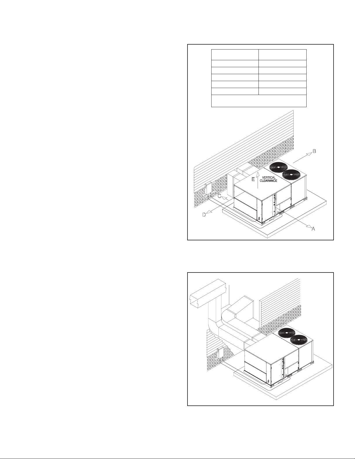
Clearances
The following minimum clearances must be observed for
proper unit performance and serviceability.
1 Provide 48" [1219.2 mm] minimum clearance at the front
of the unit. Provide 18" [457.2 mm] minimum clearance
at all other sides of the unit.
2 Provide 60" [1524 mm] minimum clearance between top
of unit and maximum 3 foot [.91 m] overhang.
3 Unit is design certified for application on combustible
flooring with 0" [0 mm] minimum clearance.
4 See Figure 7 for illustration of minimum installation-ser-
vice clearances.
Figure 7: Outside Slab Installation, Basement or Crawl
Space Distribution System
Figure 8: Outside Slab Installation, Closet Distribution
System. Slab Floor Construction
A0739-03
A0741-03
Recommended
Clearance
Location
48” [1219.2 mm] A - Front
18” [457.2 mm] B - Condenser Coil
18” [457.2 mm] C - Duct Side
18”* [457.2 mm] D - Evaporator End
60” [1524 mm] E - Above
*Without Economizer. 48” [1219.2 mm] With
*Economizer
Page 16

16 IM 866
Rooftop Installation
1 Before locating the unit on the roof, make sure that the
strength of the roof and beams is adequate at that point to
support the weight involved. This is very important and
user’s responsibility.
2 For rigging and roofcurb details, see Figures 9 and 10.
Use field-furnished spreaders.
3 For roofcurb assembly, see Roofcurb Installation Instruc-
tions.
4 If the roofcurb is not used, provisions for disposing of
condensate water runoff must be provided.
5 The unit should be placed on a solid and level roofcurb or
platform of adequate strength. See Figure 11.
6 The location of the unit on the roof should be such as to
provide proper access for inspection and servicing.
IMPORTANT: If unit will not be put into service immediately,
cover supply and return openings to prevent excessive condensation.
Figure 9: Rigging For Lifting
A0719-02
A0719-03
CORNER WEIGHTS BY PERCENTAGE
ABCD
33% 27% 17% 23%
Figure 10: Roofcurb Installation
A0744-03
.63” [14.9 mm] SHACKLE
(EACH CORNER)
41.19”
[1046.4 mm]
35.31”
[896.6 mm]
CENTER OF
GRAVITY
INSTALL GASKET
NAILING STRIP
DUCT FLANGE NOT
TO EXCEED 1" [25.4 mm]
UNIT
ROOFCURB
SUPPLY DUCT
CAULK ALL JOINTS
RETURN DUCT
WATERTIGHT
Page 17

IM 866
17
Ductwork
Ductwork should be fabricated by the installing contractor in
accordance with local codes and NFPA90A. Industry manuals
may be used as a guide when sizing and designing the duct
system - contact Air Conditioning Contractors of America,
1513 16th St. N.W., Washington, D.C. 20036.
The unit should be placed as close to the space to be air conditioned as possible allowing clearance dimensions as indicated.
Ducts should be run as directly as possible to supply and
return outlets. Use of non-flammable waterproof flexible connectors on both supply and return connections at the unit to
reduce noise transmission is recommended.
It is preferable to install the unit on the roof of the structure if
the registers or diffusers are located on the wall or in the ceiling. A slab installation could be considered when the registers
are low on a wall or in the floor.
On ductwork exposed to outside air conditions of temperature
and humidity, use a minimum of 2" [50.8 mm] of insulation
and a vapor barrier. Distribution system in attic, furred space
or crawl space should be insulated with at least 2" [50.8 mm]
of insulation with vapor barrier. One-half to 1" [25.4 mm]
thickness of insulation is usually sufficient for ductwork inside
the air conditioned space.
Balancing dampers should be provided for each branch duct in
the supply system. Ductwork should be properly supported
from the structure.
When installing ductwork, consider the following items:
1 Noncombustible flexible connectors should be used
between ductwork and unit to reduce noise and vibration
transmission into the ductwork.
2 When auxiliary heaters are installed, use noncombustible
flexible connectors and clearance to combustible material
of 0" [0 mm] for the first 3 feet [.91 m] of discharge duct.
Clearance to unit top and side is 0" [0 mm].
Filters
This unit is provided with 6 - 2" x 18" x 18" [51mm x 457 mm
x 457 mm] disposable filters. When replacing filters, ensure
they are inserted fully to the back to prevent bypass.
Conversion Procedure
Downflow To Horizontal
1 Remove the screws and covers from the outside of the
supply and return sections.
2 Install the covers over the bottom supply and return open-
ings, painted side up inserting the leading flange under the
bracket provided. Place the back flange to the top of the
front bracket provided. See Figure 12.
3 Secure the return and supply cover to the front bracket
with one (1) screw.
Condensate Drain
The condensate drain connection of the evaporator is
1" [25.4 mm] nominal female pipe thread. IMPORTANT:
Install a condensate trap to ensure proper condensate drainage.
See Figure 13.
FIGURE 11: Flat Rooftop Installation, Attic or Drop Ceiling
Distribution System. Mounted on Roofcurb. Curb Must Be
Level
A0742-04
Figure 12: Cover Gasket Detail
A0725-01
REAR PANEL
FRONT BRACKET
SUPPLY OR RETURN COVER
INSULATION
BACK
BRACKET
INSULATION
BASE PAN
BASE RAIL
NOTE: COVER SLIDES
UNDER BACK
BRACKET FLANGE.
NOTE: COVER FITS ON
TOP OF FRONT
BRACKET FLANGE.
Do not, under any circumstances, connect return ductwork
to any other heat producing device such as a fireplace
insert, stove, etc. Unauthorized use of such devices may
result in fire, carbon monoxide poisoning, explosion, property damage, severe personal injury or death.
▲▲
DANGER
!
Page 18

18 IM 866
Electrical Wiring
Field wiring must comply with the National Electrical Code
(CEC in Canada) and local ordinances that may apply.
Power Wiring
1 This unit incorporates single-point electrical connections
for the unit and electric heat accessory.
2 It is important that proper electrical power is available to
the unit. Voltage should not vary more than 10% from the
values marked on the unit rating plate. Phase voltages must
be balanced within 3%.
3 For branch circuit wiring (main power supply to unit dis-
connect), the minimum wire size can be determined from
Table 1 using the circuit ampacity found on the unit
nameplate or from Tables 3, 4, 5 and 6.
4 The branch circuit wire must be sized in accordance with
the National Electrical Code (C.E.C. in Canada) and local
ordinances that may apply using the minimum circuit
ampacity found on the unit rating plate.
5 Field-installed power wiring must be run through grounded
rain-tight conduit attached to the unit power entry panel
and connected as follows:
UNITS WITHOUT ELECTRIC HEAT - Connect
power wiring to the power terminal block located on the
left side of the electric heat compartment. Connect the
ground wire to the adjacent ground lug.
UNITS WITH FACTORY INSTALLED ELECTRIC
HEAT - Connect power wiring to the power terminal
block located on the electric heater kit. Connect the ground
wire to the adjacent ground lug. DO NOT connect aluminum wiring directly to the electric heater terminal block.
Wiring to the unit contactors is factory-connected.
6 For field installation of an electric heater kit, follow the
instructions below. Refer to the information supplied with
the kit.
a Removing screws as required, open heater access door
and detach adjacent power entry panel.
b Remove wires to unit contactor (1L1, 1L2, 1L3) from
unit terminal block on the left side of the electric heat
compartment. Remove and discard the terminal block
and the adjacent ground lug.
c Remove the heater kit block-off panel and install the
heater kit in its place using 9 of the 12 screws previously
removed.
d Connect the unit contactor wires (1L1, 1L2, 1L3) to the
compressor fuse block on the heater kit.
e Re-install the power entry panel & run conduit and the
proper size field wiring through the opening in the
panel.
f Connect field wiring to the power terminal block located
on the electric heater kit. Connect ground wire to the
adjacent ground lug.
Figure 14:Branch Circuit Disconnect Location
A0742-04
Figure 13: Condensate Drain
3”
[76 mm]
3”
[76 mm]
TABLE 1: COPPER WIRE SIZE — AWG (1% VOLTAGE DROP)
300
250
200
150
100
50
Supply
Wire
Length
Feet
4
4
6
8
10
14
15
3
4
4
6
8
12
20
2
3
4
6
8
10
25
2
3
4
4
6
10
30
1
2
3
4
6
8
35
1/0
1
2
4
6
8
40
1/0
1
2
3
4
6
45
2/0
1/0
1
3
4
6
50
2/0
1/0
1
2
4
6
55
3/0
2/0
1/0
2
3
4
60
3/0
2/0
1/0
1
3
4
65
3/0
2/0
1/0
1
2
4
70
4/0
3/0
2/0
1/0
2
3
75
4/0
3/0
2/0
1/0
2
3
80
4/0
3/0
2/0
1/0
1
3
85
4/0
4/0
3/0
1/0
1
2
90
250
4/0
3/0
2/0
1
2
95
250
4/0
3/0
2/0
1
2
100
250
4/0
3/0
2/0
1
2
105
250
4/0
3/0
2/0
1/0
2
110
300
250
4/0
2/0
1/0
1
115
300
250
4/0
3/0
1/0
1
120
300
250
4/0
3/0
1/0
1
125
Circuit Ampacity
NOTE:
1. Wire size based on 60ºC type copper conductors below 100 ampacity. 2. Wire size based on 75ºC type copper conductors for 100 ampacity and above.
Page 19

IM 866
19
g Connect heater kit control plug to the receptacle on the
control wiring harness.
h Close heater access door and secure with screws previ-
ously removed.
Control Wiring (Class II)
1 Low voltage wiring should not be run in conduit with
power wiring.
2 Control wiring is routed through the 7/8" [22 mm] hole in
the unit side panel. See Figures 1 & 15. Use a minimum
#18 AWG thermostat wire. For wire lengths exceeding
50' [15.24 m] use #16 AWG thermostat wire. Connect the
control wiring to the low voltage terminal block located
below the unit control box.
3 It is necessary that only approved thermostats be used.
Please contact your McQuay Representative.
4 Figure 17 shows representative low voltage connection
diagrams. Read your thermostat installation instructions
for any special requirements for your specific thermostat.
Internal Wiring
1 A diagram of the internal wiring of this unit is located on
the inside of the control access panel and in this manual. If
any of the original wiring must be replaced, the wire gauge
and insulation must be the same as original wiring.
208 Volt Applications
Transformer is factory-wired for 220 volts on 200/220 volt
models and must be changed for 200-volt applications. See unit
wiring diagram for 200-volt wiring.
Grounding
GROUNDING MAY ALSO BE ACCOMPLISHED BY
GROUNDING THE POWER LINE CONDUIT TO THE
UNIT. MAKE SURE THE CONDUIT NUT LOCKING
TEETH HAVE PIERCED THE INSULATING PAINT FILM
OF THE SIDE PANEL.
Thermostat
The thermostat should be mounted on an inside wall about
five feet above the floor in a location where it will not be
affected by unconditioned air, sun, or drafts from open doors
or other sources. READ installation instructions in air conditioner thermostat package CAREFULLY because each has
some different wiring requirements.
The low voltage wiring should be sized as shown in Table 2.
Install the room thermostat in accordance with the instruction
sheet packed in the box with the thermostat.
A0728-02
A0728-03
Figure 15: Base Entry Locations
(2) CAP
PLUGS
SIDE
CONTROL
ENTRY
BASE
CONTROL
ENTRY
SIDE
POWER
ENTRY
BASE
POWER
ENTRY
Figure 16
The unit must be permanently grounded. A grounding lug is
provided in the electric heat access area for a ground wire.
Failure to ground this unit can result in fire or electrical
shock causing property damage, severe personal injury or
death.
▲▲
DANGER
!
Table 2
FIELD WIRE SIZE FOR 24 VOLT THERMOSTAT CIRCUITS
SOLID COPPER WIRE - AWG.
3.0 16 14 12 10 10 10
2.5 16 14 12 12 12 10
2.0 18 16 14 12 12 10
50 100 150 200 250 300
Length of Run – Feet (1)
Thermostat Load -
Amps
(1) The total wire length is the distance from the furnace to the thermostat and back to the furnace.
NOTE: DO NOT USE CONTROL WIRING SMALLER THAN NO. 18
AWG.
Page 20

20 IM 866
Indoor Air Flow Data
Belt-drive blower models have motor sheaves set for proper
CFM at a typical external static. See Tables C through G for
blower performance.
Crankcase Heat (Optional)
Crankcase heat is not required on scroll type compressors, but
may be desirable under certain conditions.
Pre-Start Check
1 Is unit properly located and slightly slanted toward indoor
condensate drain?
2 Is ductwork insulated, weatherproofed, with proper spac-
ing to combustible materials?
3 Is air free to travel to and from outdoor coil? (See Figure
5.)
4 Is the wiring correct, tight, and according to unit wiring
diagram?
5 Is unit grounded?
6 Are field supplied air filters in place and clean?
7 Do the outdoor fan and indoor blower turn freely without
rubbing, and are they tight on the motor shafts?
Startup
1 Turn thermostat to “OFF,” turn “on” power supply at
disconnect switch.
2 Turn temperature setting as high as it will go.
3 Turn fan switch to “ON.”
4 Indoor blower should run. Be sure it is running in the
right direction.
5 Turn fan switch to “AUTO.” Turn system switch to
“COOL” and turn temperature setting below room temperature. Unit should run in cooling mode.
6 Is outdoor fan operating correctly in the right direction?
7 Is compressor running correctly.
Record the following after the unit has run some time.
a Operating Mode _____________________________
b Discharge Pressures (High) ___________PSIG [kPa]
c Vapor Pressure at Compressors (Low)___PSIG [kPa]
d Vapor Line Temperature at Compressors ___°F [C°].
e Indoor Dry Bulb_______________________°F [C°].
f Indoor Wet Bulb ______________________°F [C°].
g Outdoor Dry Bulb _____________________°F [C°].
h Outdoor Wet Bulb _____________________°F [C°].
i Voltage at Contactor _____________________Volts
j Current at Contactors ____________________ Amps
k Model Number ______________________________
A0823-01
Figure 17: Thermostat Connections Diagram
Page 21

IM 866
21
l Serial Number_______________________________
m Location ___________________________________
n Owner _____________________________________
o Date_______________________________________
8 Turn thermostat system switch to “HEAT.” Unit com-
pressors should stop. Raise temperature setting to above
room temperature. Unit should run in heating mode and
auxiliary heaters, if installed, should come on.
9 Check the refrigerant charge using the instructions
located on unit charging chart. Replace service port
caps. Service port cores are for system access only and
will leak if not tightly capped.
10 Adjust discharge air grilles and balance system.
11 Check ducts for condensation and air leaks.
12 Check unit for tubing and sheet metal rattles.
13 Instruct the owner on operation and maintenance.
14 Leave “INSTALLATION” and ”USE AND CARE“
instructions with owner
Operation
Cooling Mode
With thermostat in the cool mode, fan auto and the room temperature higher than the thermostat setting:
1 Indoor blower contactor is energized through thermostat
contact (G).
2 Compressor contactors are energized through thermostat
contacts (Y1) & (Y2) and high pressure controls.
3 Economizer enthalpy control (if installed) controls opera-
tion of first-stage cooling and positions fresh air damper
to maintain mixed air temperature. Second-stage cooling
operates normally as required by second stage of thermostats.
4 The system will continue in cooling operation as long as
all safety controls are closed, until the thermostat is satisfied.
Heating Mode
With the thermostat in heat mode, fan on auto, and the room
temperature lower than the thermostat setting, the Indoor
blower contactor is energized through thermostat contact (G).
In the heating mode, the thermostat will energize one or more
supplementary heaters.
Miscellaneous
Replacement Parts
To find your local McQuay Certified Parts Distributor, go to
www.mcquay.com and select Parts Locator.
Only electric heater kits supplied by this manufacturer as
described in this publication have been designed, tested,
and evaluated for use with this unit. Use of any other manufactured electric heaters installed within this unit may cause
hazardous conditions resulting in property damage, fire,
bodily injury or death.
▲▲
DANGER
!
Page 22

22 IM 866
AIR-FLOW DATA 7.5 TON [26.4 kW] MODELS
AIRFLOW DATA TABLES
Page 23

IM 866
23
AIR-FLOW DATA 8.5 TON [29.9 kW] MODELS
Page 24

24 IM 866
AIR-FLOW DATA 10 TON [35.2 kW] MODELS
Page 25

IM 866
25
AIR-FLOW DATA 12.5 TON [44 kW] MODELS
COMPONENT AIR RESISTANCE
IWC 12.5 TON [44 kW]
AIRFLOW CORRECTION FACTORS
12.5 TON [44 kW]
Page 26

26 IM 866
Heater Kit Characteristics
Table 3: Auxiliary Heater Kits Characteristics and Application (7.5 Ton [26.4 kW] Models)
UNIT MODEL
NUMBER
MPS
007AYCL
007AYCM
007AYDL
007AYDM
007AYYL
007AYYM
REBMUN
-BMLR
LC090A
MC090A
LD090A
LEDOMTINU
TIKRETAEH
.ONLEDOM
-JJXR
ENON
C01CC
C51CC
C02CC
C03CC
C13CC
C04CC
C14CC
ENON
C01CC
C51CC
C02CC
C03CC
C13CC
C04CC
4CC
C1
ENON
D01CC
D51CC
D02CC
D03CC
D13CC
D04CC
D14CC
—
—
—
WkRETAEH
V042/802@
—
6.9/2.7
4.41/8.01
2.91/4.41
8.82/6.12
8.82/6.12
4.83/8.82
4.83/8.82
—
6.9/2.7
4.41/8.01
2.91/4.41
8.82/6.12
8.82/6.12
4.83/8.82
4.83/8.82
V084@
6.9
4.41
2.91
8.82
8.82
4.83
4.83
6
—
ALFTIKRETAEH
1.32/0.02
6.43/0.03
2.64/0.04
3.96/0.06
3.96/0.06
4.29/1.08
4.29/1.08
1.32/0.02
6.43/0.03
2.64/0.04
3.96/0.0
3.96/0.06
4.29/1.08
4.29/1.08
42
5
.11
3.71
1.32
6.43
6.43
2.64
2.64
42
72
43
94
94
36
36
.TKC.NIMTINU
YTICAPMA
34/34
34/34
45/84
86/16
79/68
79/68
621/111
621/111
94/94
94/94
06/45
47/76
301/29
301/29
231/711
231/711
ROESUF.XAM
EZIS.RKB.TKC
TSUM.RKB.TKC(
EPYTRCAHEB
)ASUROF
05/05
05/05
06/05
07/07
001/09
001/09
051/521
051/521
06/06
06/06
06/06
08/07
011/001
011/001
051/521
051/521
03
03
03
53
05
05
07
07
MD090A
0A
MY090A
ENON
D01CC
D51CC
D02CC
D03CC
D13CC
D04CC
4CC
D1
ENON
Y01CC
LY09
Y51CC
Y02CC
Y03CC
Y04CC
ENON
Y01CC
Y51CC
Y02CC
Y03CC
Y04CC
—
6.9
4.41
2.91
8.82
8.82
4.83
4.83
V006@
—
6.9
4.41
2.91
8.82
4.83
—
6.9
4.41
2.91
8.82
4.83
—
—
—
72
5.11
3.71
1.32
6.43
6.43
2.64
2.64
2.9
9.31
5.81
7.72
0.73
2.9
9.31
5.81
7.72
0.73
72
13
83
25
25
76
76
81
81
32
92
04
25
22
22
82
43
54
75
03
03
53
04
06
06
07
07
02
02
52
03
04
06
52
52
03
53
54
06
Page 27

IM 866
27
Heater Kit Characteristics (continued)
Table 4: Auxiliary Heater Kits Characteristics and Application (8.5 Ton [29.9 kW] Models)
008AYCL
008AYCM
008AYDL
008AYDM
008AYYL
008AYYM
UNIT MODEL
NUMBER
MPS
REBMUN
-BMLR
LC201A
MC201A
LD201A
LEDOMTINU
TIKRETAEH
.ONLEDOM
-JJXR
ENON
C01CC
C51CC
C02CC
C03CC
C13CC
C04CC
C14CC
ENON
C01CC
C51CC
C02CC
C03CC
C13CC
C04CC
4CC
C1
ENON
D01CC
D51CC
D02CC
D03CC
D13CC
D04CC
D14CC
—
—
—
WkRETAEH
V042/802@
—
6.9/2.7
4.41/8.01
2.91/4.41
8.82/6.12
8.82/6.12
4.83/8.82
4.83/8.82
—
6.9/2.7
4.41/8.01
2.91/4.41
8.82/6.12
8.82/6.12
4.83/8.82
4.83/8.82
V084@
6.9
4.41
2.91
8.82
8.82
4.83
4.83
6
—
ALFTIKRETAEH
1.32/0.02
6.43/0.03
2.64/0.04
3.96/0.06
3.96/0.06
4.29/1.08
4.29/1.08
1.32/0.02
6.43/0.03
2.64/0.04
3.96/0.0
3.96/0.06
4.29/1.08
4.29/1.08
5
.11
3.71
1.32
6.43
6.43
2.64
2.64
.TKC.NIMTINU
YTICAPMA
44/44
44/44
45/84
86/06
79/58
79/58
621/111
621/111
94/94
94/94
06/45
47/76
301/29
301/29
231/711
231/711
42
42
72
43
94
94
36
36
ROESUF.XAM
EZIS.RKB.TKC
TSUM.RKB.TKC(
EPYTRCAHEB
)ASUROF
05/05
05/05
06/05
07/06
001/09
001/09
051/521
051/521
06/06
06/06
06/06
08/07
011/001
011/001
051/521
051/521
03
03
03
53
05
05
07
07
MD201A
1A
LY20
MY201A
ENON
D01CC
D51CC
D02CC
D03CC
D13CC
D04CC
4CC
D1
ENON
Y01CC
Y51CC
Y02CC
Y03CC
Y04CC
ENON
Y01CC
Y51CC
Y02CC
Y03CC
Y04CC
—
6.9
4.41
2.91
8.82
8.82
4.83
4.83
V006@
—
6.9
4.41
2.91
8.82
4.83
—
6.9
4.41
2.91
8.82
4.83
—
—
—
72
5.11
3.71
1.32
6.43
6.43
2.64
2.64
2.9
9.31
5.81
7.72
0.73
2.9
9.31
5.81
7.72
0.73
72
13
83
25
25
76
76
91
91
32
92
04
25
32
32
82
43
54
75
03
03
53
04
06
06
07
07
02
02
52
03
04
06
52
52
03
53
54
06
Page 28

28 IM 866
Heater Kit Characteristics (continued)
Table 5: Auxiliary Heater Kits Characteristics and Application (10 Ton [35.2 kW] Models)
010AYCL
010AYCM
010AYDL
010AYDM
010AYYL
010AYYM
UNIT MODEL
NUMBER
MPS
REBMUN
-BMLR
LC021A
MC021A
LD021A
MD021A
LY021A
MY021A
LEDOMTINU
TIKRETAEH
.ONLEDOM
-JJXR
ENON
C01CC
C51CC
C02CC
C03CC
C13CC
C04CC
C14CC
C05CC
C15CC
ENON
C01CC
C51CC
C02CC
C03CC
C13CC
C04CC
C14CC
C05CC
C15CC
ENON
D01CC
D51CC
C
D02C
D03CC
D13CC
D04CC
D14CC
D05CC
D15CC
ENON
D01CC
D51CC
D02CC
D03CC
D13CC
D04CC
D14CC
D05CC
D15CC
ENON
Y01CC
Y51CC
Y02CC
Y03CC
Y04CC
Y05CC
ENON
Y01CC
Y51CC
Y02CC
Y03CC
Y04CC
Y05CC
WkRETAEH
V042/802@
—
6.9/2.7
4.41/8.01
2.91/4.41
8.82/6.12
8.82/6.12
4.83/8.82
4.83/8.82
0.84/1.63
0.84/1.63
—
6.9/2.7
4.41/8.01
2.91/4.41
8.82/6.12
8.82/6.12
4.83/8.82
4.83/8.82
0.84/1.63
0.84/1.63
V084@
—
6.9
4.41
2.91
8.82
8.82
4.83
4.83
0.84
0.84
—
6.9
4.41
2.91
8.82
8.82
4.83
4.83
0.84
0.84
V006@
—
6.9
4.41
2.91
8.82
4.83
0.84
—
6.9
4.41
2.91
8.82
4.83
0.84
4
ALFTIKRETAEH
—
1.32/0.02
6.43/0.03
2.64/0.04
3.96/0.06
3.96/0.06
4.29/1.08
4.29/1.08
5.511/0.001
5.511/1.001
—
1.32/0.02
6.43/0.03
2.64/0.04
3.9
6/0.06
3.96/0.06
4.29/1.08
4.29/1.08
5.511/0.001
5.511/1.001
—
5.11
3.71
1.32
6.43
6.43
2.64
2.64
7.75
7
.75
—
5.11
3.71
1.32
6.43
6.43
2.64
2.64
7.75
7.75
—
2.9
9.31
5.81
7.72
0.73
2.6
—
2.9
9.31
5.81
7.72
0.73
2.64
.TKC.NIMTINU
YTICAPMA
95/95
95/95
95/95
86/16
79/68
79/68
621/111
621/111
551/631
551/631
35/35
35/35
45/35
86/06
79/58
79/58
621/111
621/111
1/631
55
551/631
92
92
92
43
94
94
36
36
87
87
23
23
23
83
25
25
76
76
18
18
22
22
32
92
04
25
36
62
62
82
43
54
75
86
ROESUF.XAM
EZIS.RKB.TKC
TSUM.RKB.TKC(
EPYTRCAHEB
)ASUROF
07/07
07/07
07/07
07/07
001/09
001/09
051/521
051/521
571/051
571/051
06/06
06/06
06/06
07/06
001/09
001/09
051/521
051/521
571/051
571/051
53
53
53
53
05
05
07
07
08
08
04
04
04
04
06
6
0
07
07
09
09
52
52
52
03
04
06
07
03
03
03
53
54
06
07
Page 29

IM 866
29
Heater Kit Characteristics (continued)
Table 6: Auxiliary Heater Kits Characteristics and Application (12.5 Ton [44 kW] Models)
012AYCL
012AYCM
012AYDL
012AYDM
012AYYL
012AYYM
UNIT MODEL
NUMBER
MPS
REBMUN
-BMLR
LC051A
MC051A
LD051A
MD051A
LY051A
MY051A
LEDOMTINU
TIKRETAEH
.ONLEDOM
-JJXR
ENON
C01CC
C51CC
C02CC
C03CC
C13CC
C04CC
C14CC
C05CC
C15CC
ENON
C01CC
C51CC
C02CC
C03CC
C13CC
C04CC
C14CC
C05CC
C15CC
ENON
D01CC
51CC
D
D02CC
D03CC
D13CC
D04CC
D14CC
D05CC
D15CC
ENON
D01CC
D51CC
D02CC
D03CC
D13CC
D04CC
D14CC
D05CC
D15CC
ENON
Y01CC
Y51CC
Y02CC
Y03CC
Y13CC
Y04CC
Y14CC
Y05CC
ENON
Y01CC
Y51CC
Y02CC
Y03CC
Y13CC
Y04CC
Y14CC
Y05CC
WkRETAEH
V042/802@
—
6.9/2.7
4.41/8.01
2.91/4.41
8.82/6.12
8.82/6.12
4.
83/8.82
4.83/8.82
0.84/1.63
0.84/1.63
—
6.9/2
.7
4.41/8.01
2.91/4.41
8.82/6.12
8.82/6.12
4.83/8.82
4.83/8.82
0.84/1.63
0.84/1.63
V084@
—
6.9
4.41
2.91
8.82
8.82
4.83
4.83
0.84
0.84
—
6.9
4.41
2.91
8.82
8.82
4.83
4.83
0.84
0.84
V006@
—
6.9
4.41
2.91
8.82
8.82
4.83
4.83
.84
0
—
6.9
4.41
2.91
8.82
8.82
4.83
4.83
0.84
ALFTIKRETAEH
—
1.32/0.02
6.43/0.03
2.64/0.04
3.96/0.06
3.96/0.06
4.29/1.08
4.29/1.08
11/0.001
5.5
5.511/1.001
—
1.32/0.02
6.43/0.03
2.64/0.04
3.96/0.06
3.96/0.06
4.29/1.08
4.29/1.08
5.511/0.001
5.511/1.001
—
5.11
3.71
1.32
6.43
6.43
2.64
2.64
7.75
7.75
—
5.11
3.71
1.32
6.43
6.43
2.64
2.64
7.75
7.75
—
2.9
9.31
5.81
7.72
7.72
0.73
0.73
2.64
—
2.9
9.31
5.81
7.72
7.72
0.73
0.73
2.64
.TKC.NIMTINU
YTICAPMA
17/17
17/17
17/17
77/17
601/49
601/49
531/911
531/911
461/441
461/441
17/17
17/17
17/17
77/17
601/49
601/49
531/911
531/911
461/441
461/441
63
63
63
83
25
25
76
76
18
18
93
93
93
24
65
65
17
17
58
58
13
13
13
43
54
54
75
75
86
13
13
13
43
54
54
75
75
6
8
ROESUF.XAM
EZIS.RKB.TKC
TSUM.RKB.TKC(
EPYTRCAHEB
)ASUROF
09/09
09/09
09/09
09/09
011/001
011/001
051/521
051/521
571/051
571/051
09/09
09/09
09/09
09/09
011/001
011/001
051/521
051/521
571/051
571/051
54
54
54
54
06
06
07
07
09
09
54
5
4
54
54
06
06
08
08
09
09
53
53
53
53
54
54
06
06
07
53
53
53
53
54
54
06
06
07
Page 30
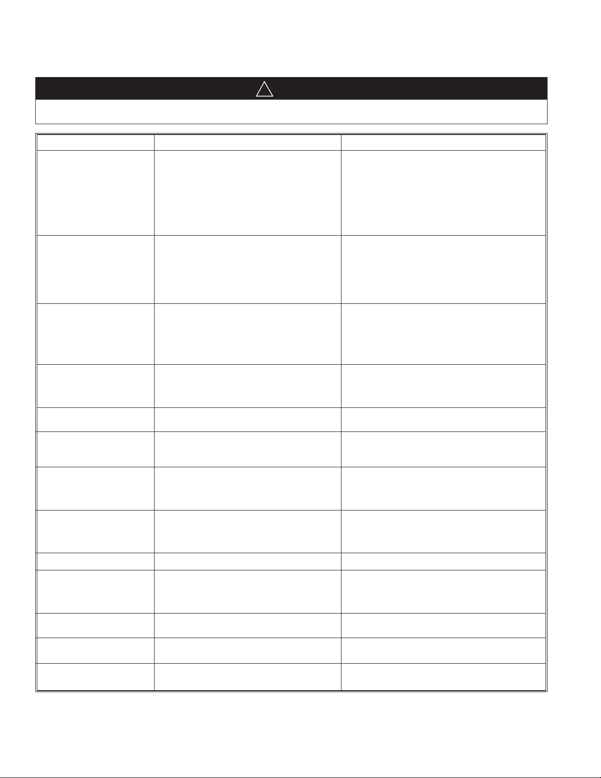
30 IM 866
SYMPTOM POSSIBLE CAUSE REMEDY
Unit will not run • Power off or loose electrical connection • Check for correct voltage at compressor contactor in control
box
• Thermostat out of calibration-set too high • Reset
• Defective contactor • Check for 24 volts at contactor coil - replace if contacts are
open
• Blown fuses • Replace fuses
• Transformer defective • Check wiring-replace transformer
• High pressure control open (if provided) • Reset-also see high head pressure remedy-
• Interconnecting low voltage wiring damaged • Replace thermostat wiring
Condenser fan runs, compressor • Run capacitor defective (single phase only) • Replace
doesn’t • Loose connection • Check for correct voltage at compressor -
check & tighten all connections
• Compressor stuck, grounded or open motor winding • Wait at least 2 hours for overload to reset.
open internal overload. If still open, replace the compressor.
• Low voltage condition At compressor terminals, voltage must be within 10% of rating
plate volts when unit is operating.
Insufficient cooling • Improperly sized unit • Recalculate load
• Improper airflow • Check - should be approximately 400 CFM [188.78 L/s] per ton.
• Incorrect refrigerant charge • Charge per procedure attached to unit service panel.
• Air, non-condensibles or moisture in system • Recover refrigerant, evacuate & recharge, add filter drier
• Incorrect voltage • At compressor terminals, voltage must be within 10% of rating
plate volts when unit is operating.
Compressor short cycles • Incorrect voltage • At compressor terminals, voltage must be ± 10% of
nameplate marking when unit is operating.
• Defective overload protector • Replace - check for correct voltage
• Refrigerant undercharge • Add refrigerant
Registers sweat • Low evaporator airflow • Increase speed of blower or reduce restriction - replace air
filter
High head-low vapor pressures • Restriction in liquid line, expansion device or filter drier • Remove or replace defective component
• Flow check piston size too small • Change to correct size piston
• Incorrect capillary tubes • Change coil assembly
High head-high or normal vapor • Dirty condenser coil • Clean coil
pressure - Cooling mode • Refrigerant overcharge • Correct system charge
• Condenser fan not running • Repair or replace
• Air or non-condensibles in system • Recover refrigerant, evacuate & recharge
High head-high or normal vapor • Low air flow - condenser coil • Check filters - correct to speed
pressure - Heating mode • Refrigerant overcharge • Correct system charge
• Air or non-condensibles in system • Recover refrigerant, evacuate & recharge
• Dirty condenser coil • Check filter - clean coil
Low head-high vapor pressures • Defective Compressor valves • Replace compressor
Low vapor - cool compressor - • Low evaporator airflow • Increase speed of blower or reduce restriction - replace air
iced evaporator coil filter
• Operating below 65°F outdoors • Add Low Ambient Kit
• Moisture in system • Recover refrigerant - evacuate & recharge - add filter drier
High vapor pressure • Excessive load • Recheck load calculation
• Defective compressor • Replace
Fluctuating head & vapor • Air or non-condensibles in system • Recover refrigerant, evacuate & recharge
pressures
Gurgle or pulsing noise at • Air or non-condensibles in system • Recover refrigerant, evacuate & recharge
expansion device or liquid line
TROUBLE SHOOTING CHART
Disconnect all power to unit before servicing. Contactor may break only one side. Failure to shut off power can cause electrical
shock resulting in personal injury or death.
▲▲
DANGER
!
Page 31

IM 866
31
Figure 18: Wiring Diagram For 7 to 10 Tons
Page 32

32 IM 866
Figure 19: Wiring Diagram For 7 to 10 Tons
Page 33

IM 866
33
Figure 20
425
[2930]
400
[2757]
375
[2585]
350
[2413]
325
[2240]
300
[2068]
275
[1896]
250
[1723]
225
[1551]
200
[1378]
175
[1206]
150
[1034]
125
[861]
SUCTION PRESSURE (PSIG) [kPa]
*CONDENSER FAN OPERATING, MAY REQUIRE
JUMPERING OF HEAD PRESSURE CONTROL
60
[413]65[448]70[482]75[517]80[551]85[586]90[620]95[655]
100
[689]
55°
[12°C]
65°
[18°C]
75°
[23°C]
85°
[29°C]
95°
[35°C]
105°
[40°C]
115°
[46°C]
LIQUID PRESSURE (PSIG) [kPa]
SYSTEM CHARGE CHART — REFRIGERANT 22
7.5 TON [29.9 kW], CIRCUIT 1 & 2
Page 34

34 IM 866
Figure 21
375
[2585]
350
[2413]
325
[2240]
300
[2068]
275
[1896]
250
[1723]
225
[1551]
200
[1378]
175
[1206]
150
[1034]
125
[861]
LIQUID PRESSURE (PSIG) [kPa]
SUCTION PRESSURE (PSIG) [kPa]
*CONDENSER FAN OPERATING, MAY REQUIRE
JUMPERING OF HEAD PRESSURE CONTROL
65
[448]70[482]75[517]
75
[517]
80
[551]85[586]90[620]95[655]
100
[689]
100
[689]
55°
[12°C]
65°
[18°C]
75°
[23°C]
85°
[29°C]
95°
[35°C]
105°
[40°C]
115°
[46°C]
60
[413]
SYSTEM CHARGE CHART — REFRIGERANT 22
8.5 TON [29.9 kW], CIRCUIT 1 & 2
Page 35

IM 866
35
Figure 22
375
[2585]
350
[2413]
325
[2240]
300
[2068]
275
[1896]
250
[1723]
225
[1551]
200
[1378]
175
[1206]
150
[1034]
SUCTION PRESSURE (PSIG) [kPa]
10 TON [35.2 kW]
SUCTION PRESSURE (PSIG) [kPa]
10 TON [35.2 kW]
65
[448]
70
[482]75[517]80[551]85[586]90[620]
95
[655]
100
[689]
55°
[12°C]
65°
[18°C]
75°
[23°C]
85°
[29°C]
95°
[35°C]
105°
[40°C]
115°
[46°C]
125
[861]
55°
[12°C]
65°
[18°C]
75°
[23°C]
85°
[29°C]
95°
[35°C]
105°
[40°C]
115°
[46°C]
LIQUID PRESSURE (PSIG) [kPa]
LIQUID PRESSURE (PSIG) [kPa]
SYSTEM CHARGE CHART — REFRIGERANT 22
10 TON [35.2 kW], CIRCUIT 1 & 2
60
[413]
65
[448]70[482]75[517]80[551]85[586]90[620]
95
[655]
100
[689]
60
[413]
350
[2413]
325
[2240]
300
[2068]
275
[1896]
250
[1723]
225
[1551]
200
[1378]
175
[1206]
150
[1034]
125
[861]
375
[2585]
Page 36

36 IM 866
Figure 23
375
[2585]
350
[2413]
325
[2240]
300
[2068]
275
[1896]
250
[1723]
225
[1551]
200
[1378]
175
[1206]
150
[1034]
SUCTION PRESSURE (PSIG) [kPa]
12.5 TON [42.20 kW]
SUCTION PRESSURE (PSIG) [kPa]
12.5 TON [42.20 kW]
65
[448]
70
[482]75[517]80[551]85[586]90[620]
95
[655]
100
[689]
55°
[12°C]
65°
[18°C]
75°
[23°C]
85°
[29°C]
95°
[35°C]
105°
[40°C]
115°
[46°C]
125
[861]
55°
[12°C]
65°
[18°C]
75°
[23°C]
85°
[29°C]
95°
[35°C]
105°
[40°C]
115°
[46°C]
LIQUID PRESSURE (PSIG) [kPa]
LIQUID PRESSURE (PSIG) [kPa]
SYSTEM CHARGE CHART — REFRIGERANT 22
12.5 TON [44 kW], CIRCUIT 1 & 2
60
[413]
65
[448]70[482]75[517]80[551]85[586]90[620]
95
[655]
100
[689]
60
[413]
350
[2413]
325
[2240]
300
[2068]
275
[1896]
250
[1723]
225
[1551]
200
[1378]
175
[1206]
150
[1034]
125
[861]
375
[2585]
Page 37

IM 866
37
Page 38

38 IM 866
Page 39

IM 866
39
Page 40

40 IM 866
© 2007 McQuay International • www.mcquay.com • 800-432-1342
 Loading...