

Page 1
Installat
ion and Ma
intenance Manual
IM 864
Group: Applied Systems
Part Number: 92-102421-01-00
Date: March 2007
Maverick I™
Commercial Packaged Rooftop System
Cooling Only or Heating & Cooling
Electric/Electric
Models MPS003AY – 005AY
3 to 5 Tons
™
ARI Standard
210/240 UAC
© 2007 McQuay International
Page 2

2 IM 864
Table of Contents
Table of Contents. . . . . . . . . . . . . . . . . . . . . . . . . . . . . 2
Introduction . . . . . . . . . . . . . . . . . . . . . . . . . . . . . . . . . 3
Checking Product Received . . . . . . . . . . . . . . . . . . . . 3
Equipment Protection . . . . . . . . . . . . . . . . . . . . . . . . . 3
Installation . . . . . . . . . . . . . . . . . . . . . . . . . . . . . . . . . . 6
General. . . . . . . . . . . . . . . . . . . . . . . . . . . . . . . . . . . . . . . . . . . . . 6
Pre-Installation Check Points . . . . . . . . . . . . . . . . . . . . . . . . 6
Location . . . . . . . . . . . . . . . . . . . . . . . . . . . . . . . . . . . . . . . . 6
Outside Slab Installation. . . . . . . . . . . . . . . . . . . . . . . . . . . . . . . . 6
Clearances . . . . . . . . . . . . . . . . . . . . . . . . . . . . . . . . . . . . . . . . . . 6
Rooftop Installation. . . . . . . . . . . . . . . . . . . . . . . . . . . . . . . . . . . . 6
Ductwork. . . . . . . . . . . . . . . . . . . . . . . . . . . . . . . . . . . . 8
Filters . . . . . . . . . . . . . . . . . . . . . . . . . . . . . . . . . . . . . . 8
Conversion Procedure . . . . . . . . . . . . . . . . . . . . . . . . 8
Condensate Drain . . . . . . . . . . . . . . . . . . . . . . . . . . . . 8
Electrical Wiring. . . . . . . . . . . . . . . . . . . . . . . . . . . . . . 9
Power Wiring . . . . . . . . . . . . . . . . . . . . . . . . . . . . . . . . . . . . . . . . 9
Control Wiring. . . . . . . . . . . . . . . . . . . . . . . . . . . . . . . . . . . . . . . . 9
Internal Wiring . . . . . . . . . . . . . . . . . . . . . . . . . . . . . . . . . . . . . . 10
208 Volt Applications . . . . . . . . . . . . . . . . . . . . . . . . . . . . . . . . . 10
Grounding. . . . . . . . . . . . . . . . . . . . . . . . . . . . . . . . . . . . . . . . . . 10
Thermostat . . . . . . . . . . . . . . . . . . . . . . . . . . . . . . . . . . . . . . . . . 10
Indoor Air Flow Data . . . . . . . . . . . . . . . . . . . . . . . . . 10
Crankcase Heat . . . . . . . . . . . . . . . . . . . . . . . . . . . . . 10
Pre-Start Check . . . . . . . . . . . . . . . . . . . . . . . . . . . . . 10
Startup . . . . . . . . . . . . . . . . . . . . . . . . . . . . . . . . . . . . 10
Operation . . . . . . . . . . . . . . . . . . . . . . . . . . . . . . . . . . 12
Auxiliary Heat . . . . . . . . . . . . . . . . . . . . . . . . . . . . . . . 12
Control System Operation . . . . . . . . . . . . . . . . . . . . . . . . . . . . . 12
Replacement Parts. . . . . . . . . . . . . . . . . . . . . . . . . . . 12
Charge Information . . . . . . . . . . . . . . . . . . . . . . . . . . 12
Troubleshooting. . . . . . . . . . . . . . . . . . . . . . . . . . . . . 12
Wiring Diagrams . . . . . . . . . . . . . . . . . . . . . . . . . . . . 12
General Data . . . . . . . . . . . . . . . . . . . . . . . . . . . . . 13-14
Miscellaneous. . . . . . . . . . . . . . . . . . . . . . . . . . . . . . . . . . . . . . . 15
Electrical Data . . . . . . . . . . . . . . . . . . . . . . . . . . . . . . . . . . . . . . 15
Airflow Performance . . . . . . . . . . . . . . . . . . . . . . . . . . . . . . . 16-19
Heater Kit Characteristics . . . . . . . . . . . . . . . . . . . . . . . . . . . 20-24
Wiring Diagrams . . . . . . . . . . . . . . . . . . . . . . . . . . . . . . . . . . 25-27
Charge Charts. . . . . . . . . . . . . . . . . . . . . . . . . . . . . . . . . . . . 28-30
Troubleshooting . . . . . . . . . . . . . . . . . . . . . . . . . . . . . . . . . . . . . 31
Page 3
IM 864
3
Introduction
This manual contains the installation and operating instructions for your packaged rooftop unit. There are a few precautions that should be taken to derive maximum satisfaction
from it. Improper installation can result in unsatisfactory operation or dangerous conditions.
Read this manual and any instructions packaged with separate
equipment required to make up the system prior to installation.
Give this manual to the owner and explain its provisions. The
owner should retain this manual for future reference.
Checking Product Received
Upon receiving the unit, inspect it for any damage from shipment. Claims for damage, either shipping or concealed, should
be filed immediately with the shipping company. Check the
unit model number, electrical characteristics, and accessories
to determine if they are correct.
Equipment Protection From The
Environment
The metal parts of this unit may be subject to rust or deterioration in adverse environmental conditions. This oxidation could
shorten the equipment’s useful life. Salt spray, fog or mist in
seacoast areas, sulphur or chlorine from lawn watering systems, and various chemical contaminants from industries such
as paper mills and petroleum refineries are especially corrosive.
If the unit is to be installed in an area where contaminants
are likely to be a problem, special attention should be
given to the equipment location and exposure.
1 Avoid having lawn sprinkler heads spray directly on the
unit cabinet.
2 In coastal areas, locate the unit on the side of the building
away from the waterfront.
3 Shielding provided by a fence or shrubs may give some
protection.
Regular maintenance will reduce the buildup of contaminents and help to protect the unit’s finish.
1 Frequent washing of the cabinet, fan blade and coil with
fresh water will remove most of the salt or other contaminants that build up on the unit.
2 Regular cleaning and waxing of the cabinet with a good
automobile polish will provide some protection.
3 A good liquid cleaner may be used several times a year to
remove matter that will not wash off with water.
Several different types of protective coatings are offered in
some areas. These coatings may provide some benefit, but the
effectiveness of such coating materials cannot be verified by
the equipment manufacturer.
The best protection is frequent cleaning, maintenance and
minimal exposure to contaminants.
The manufacturer’s warranty does not cover any damage or
defect to the air conditioner caused by the attachment or
use of any components, accessories or devices (other than
those authorized by the manufacturer) into, onto or in conjunction with the air conditioner. You should be aware that
the use of unauthorized components, accessories or
devices may adversely affect the operation of the air conditioner and may also endanger life and property. The manufacturer disclaims any responsibility for such loss or injury
resulting from the use of such unauthorized components,
accessories or devices.
▲▲
DANGER
!
Recognize this symbol as an indication of
Important Safety Information!
!
Proposition 65: This unit contains fiberglass insulation.
Respirable particles of fiberglass are known to the state of
California to cause cancer.
▲▲
WARNING
!
Disconnect all power to the unit before starting maintenance. Failure to do so can result in severe electrical shock
or death.
▲▲
DANGER
!
Page 4
4 IM 864
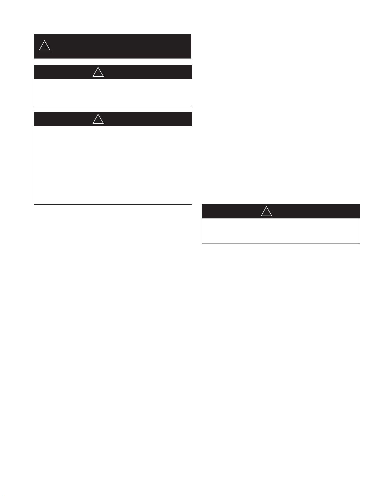
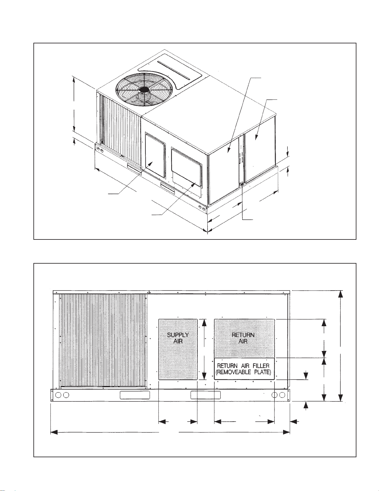
Figure 1: Unit Dimensions – Bottom View
Figure 2 : Unit Dimensions
ILL 1316
ILL1305
2
2
2
2
9.56
44.13
4.5
4.5
2.25
72.25
14.44
3.25
RETURN
AIR
SUPPLY
AIR
20
20
13.13
13.13
4.63
ELECTRIC HEAT ACCESS
COMPRESSOR/
CONTROL BOX
ACCESS
24.25
18.19
11.13
7.22
46.5
75.5
35
CONTROL ENTRY
Page 5
5IM 864
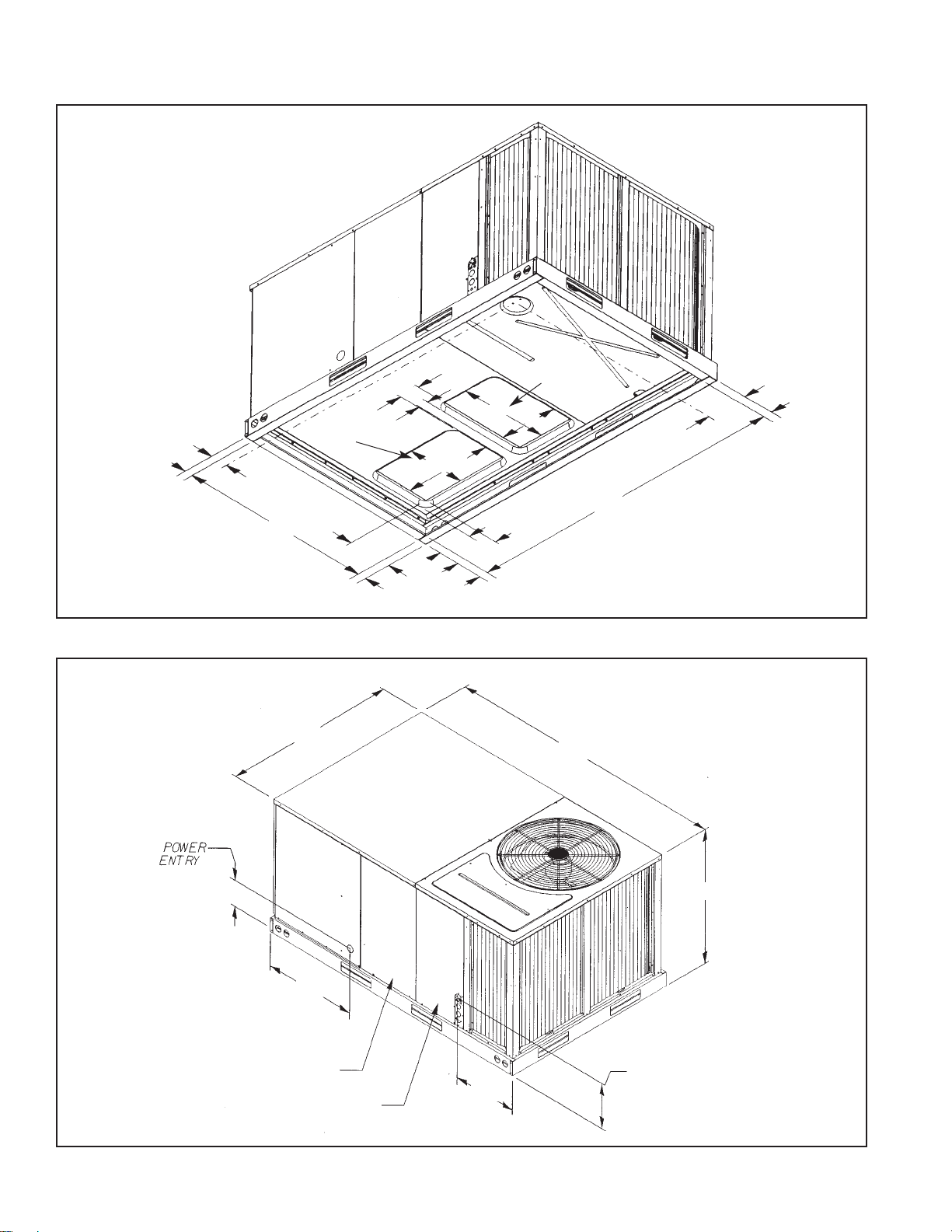
Figure 3: Unit Dimensions
Figure 4: Unit Dimensions – Back View
ILL 1304
ILL 1288
SUPPLY COVER
31.22
3.81
76.31
47.09
5.34
24
RETURN COVER/
OPTIONAL OUTDOOR
AIR HOOD LOCATION
CONDENSATE DRAIN
3/4” NPT FEMALE
BLOWER
ACCESS
COIL/FILTER
ACCESS
76.25
12.25
5.5
19.13
6.84
13.72
12.25
35
4.94
19.13
Page 6
6 IM 864
Installation
General
1 PRE-INSTALLATION CHECK-POINTS
Before attempting any installation, the following points
should be carefully considered:
a Structural strength of supporting members.
(rooftop installation)
b Clearances and provision for servicing.
c Power supply and wiring.
d Air duct connections.
e Drain facilities and connections.
f Location for minimum noise.
2 LOCATION
These units are designed for outdoor installations. They
can be mounted on a slab or rooftop. They are not to be
installed within any part of a structure such as an attic,
crawl space, closet, or any other place where condenser
air flow is restricted or other than outdoor ambient conditions prevail. Since the application of the units is of the
outdoor type, it is important to consult your local code
authorities at the time the first installation is made.
Outside Slab Installation
(Typical outdoor slab installations are shown in Figures 5 and
6.)
1 Select a location where external water drainage cannot
collect around the unit.
2 Provide a level concrete slab extending 3" beyond all four
sides of the unit. The slab should be sufficient above
grade to prevent ground water from entering the unit.
IMPORTANT: To prevent transmission of noise or vibration,
slab should not be connected to building structure.
3 The location of the unit should be such as to provide
proper access for inspection and servicing.
4 Locate unit where operating sounds will not distrub
owner or neighbors.
5 Locate unit so roof runoff water does not pour directly on
the unit. Provide gutter or other shielding at roof level.
Do not locate unit in an area where excessive snow drifting may occur or accumulate.
6 Remove compressor shipping supports (if so equipped)
after installation.
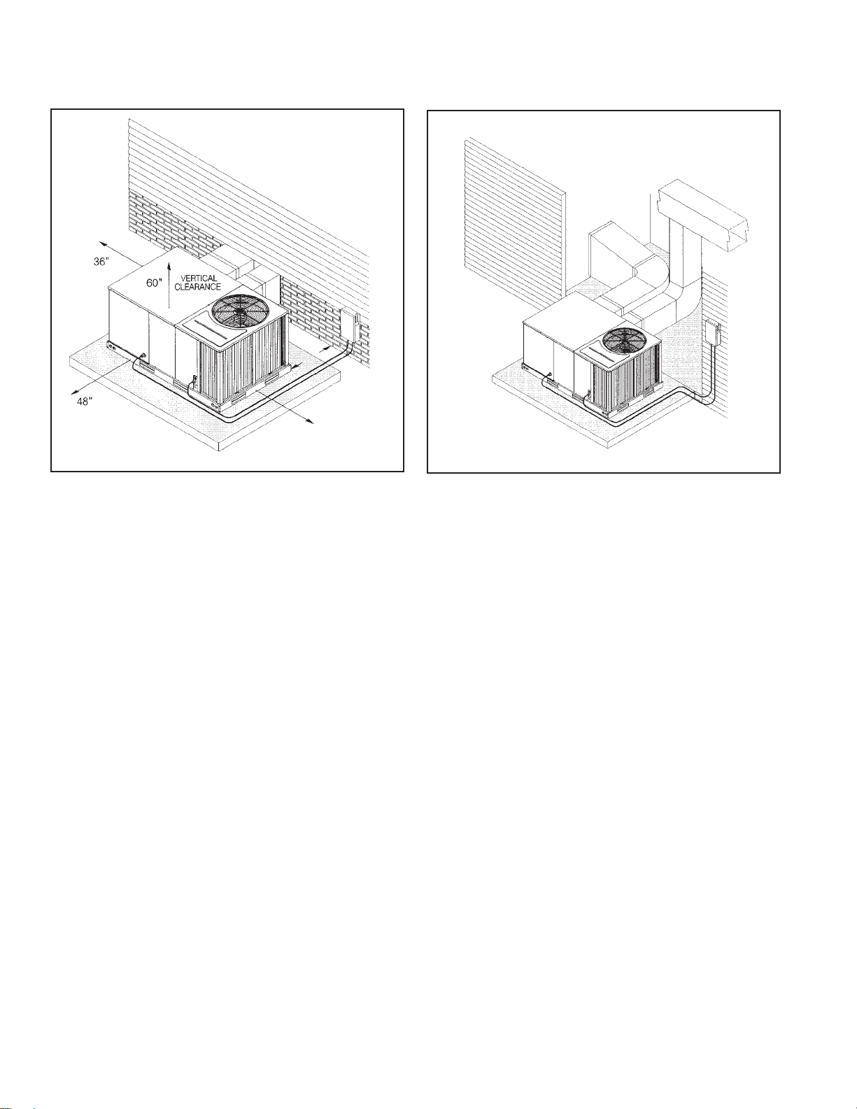
Clearances
The following minimum clearances must be observed for
proper unit performance and serviceability.
1 Provide 48" minimum clearance at the front of the unit.
Provide 36" minimum clearance at the left and right side
of the unit for service access.
2 Provide 60" minimum clearance between top of unit and
maximum 3 foot overhang.
3 Unit is design certified for application on combustible
flooring with 0" minimum clearance.
4 See Figure 5 for illustration of minimum installation-ser-
vice clearances.
Rooftop Installation
1 Before locating the unit on the roof, make sure that the
strength of the roof and beams is adequate at that point to
ILL I308
Figure 5: Outside slab installation, basement or crawl
space distribution system
18”
12”
*
Allow 57" for
economizer on duct side.
*
Figure 6: Outside slab installation, closet distribution system. Slab floor construction.
ILL I309
Page 7
IM 864
7
support the weight involved. (See specification sheet for
weight of unit.) This is very important and user’s respon-
sibility.
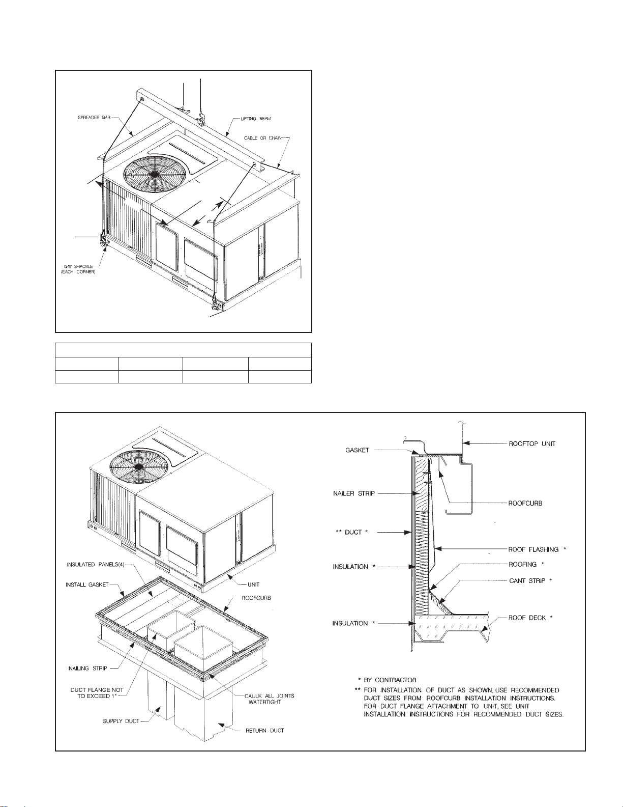
2 For rigging and roofcurb details, see Figures 7 and 8. Use
field-furnished spreaders.
3 For roofcurb assembly, see Roofcurb Installation Instruc-
tions.
4 If the roofcurb is not used, provisions for disposing of
condensate water runoff must be provided.
5 The unit should be placed on a solid and level roofcurb or
platform of adequate strength. See Figure 9.
6 The location of the unit on the roof should be such as to
provide proper access for inspection and servicing.
7 Remove compressor shipping supports (if so equipped)
after installation.
IMPORTANT: If unit will not be put into service immediately,
cover supply and return openings to prevent excessive condensation.
ILL I296
A
B
D
C
38
.25
CENTER
OF
GRAVITY
25.75
Figure 7: Package air conditioner – rigging for lifting
CORNER WEIGHTS BY PERCENTAGE
ABCD
23% 27% 23% 27%
ILL I300
ILL I301
Figure 8: Package air conditioner – roofcurb installation
Page 8
8 IM 864
Ductwork
Ductwork should be fabricated by the installing contractor in
accordance with local codes and NFPA90A. Industry manuals
may be used as a guide when sizing and designing the duct
system - contact Air Conditioning Contractors of America,
1513 16th St. N.W., Washington, D.C. 20036.
The unit should be placed as close to the space to be air conditioned as possible allowing clearance dimensions as indicated.
Ducts should be run as directly as possible to supply and
return outlets. Use of non-flammable waterproof flexible connectors on both supply and return connections at the unit to
reduce noise transmission is recommended.
It is preferable to install the unit on the roof of the structure if
the registers or diffusers are located on the wall or in the ceiling. A slab installation could be considered when the registers
are low on a wall or in the floor.
On ductwork exposed to outside air conditions of temperature
and humidity, use a minimum of 2" of insulation and a vapor
barrier. Distribution system in attic, furred space or crawl
space should be insulated with at least 2" of insulation with
vapor barrier. One-half to 1" thickness of insulation is usually
sufficient for ductwork inside the air conditioned space.
Balancing dampers should be provided for each branch duct in
the supply system. Ductwork should be properly supported
from the structure.
When installing ductwork, consider the following items:
1 Noncombustible flexible connectors should be used
between ductwork and unit to reduce noise and vibration
transmission into the ductwork.
2 When auxiliary heaters are installed, use noncombustible
flexible connectors and clearance to combustible material
of 0" for the first 3 feet of discharge duct. Clearance to
unit top and side is 0".
Filters
This unit is provided with 2 - 25" x 16" x 1" disposable filters. When replacing filters, ensure they are inserted fully to
the back to prevent bypass.
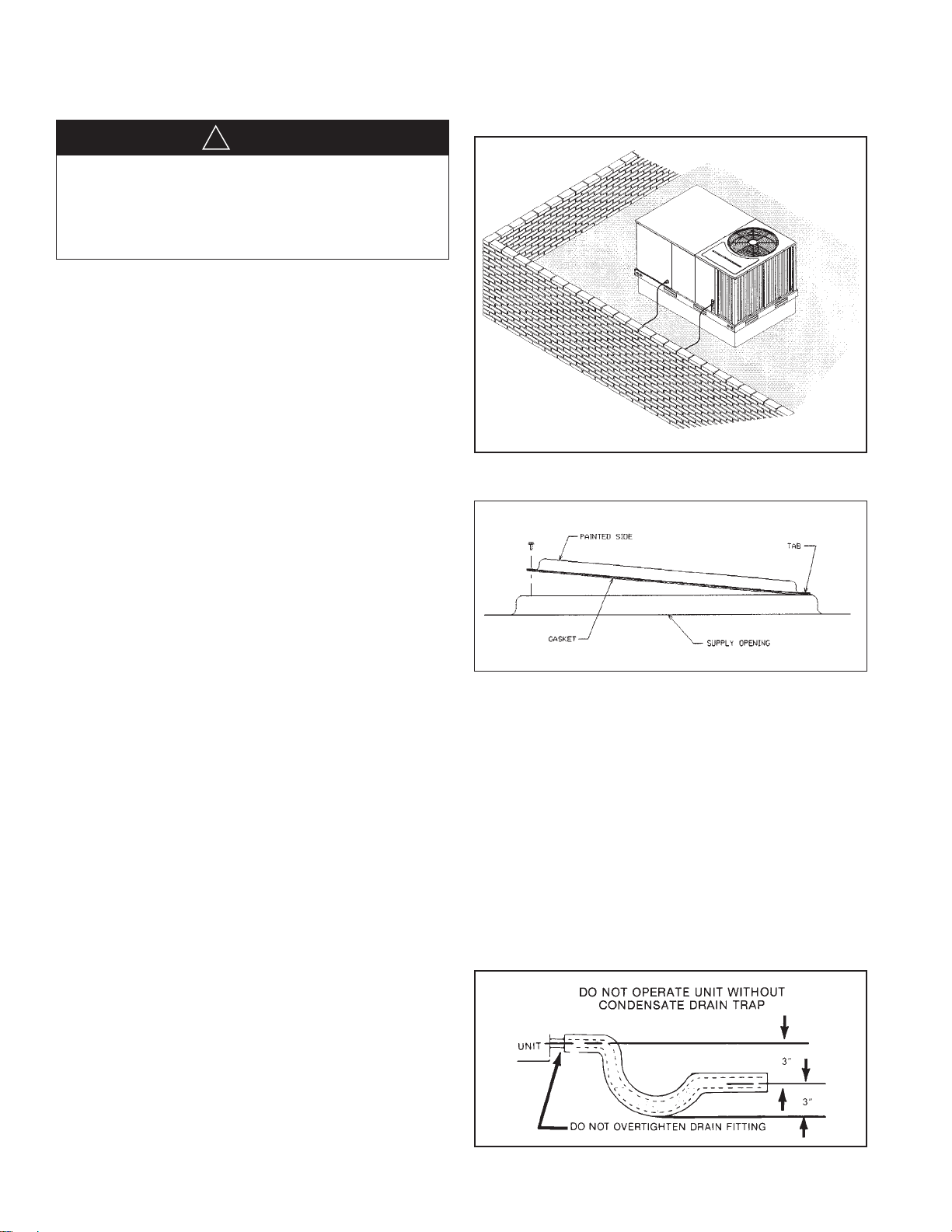
Conversion Procedure
Downflow To Horizontal
1 Remove the screws and covers from the outside of the
supply and return sections.
2 Install the covers in the bottom supply and return open-
ings with the painted side up. See Figure 10. Use the
existing gasket to seal the covers.
3 Secure the supply cover to the base of the unit with 1
screw, engaging prepunched tab in unit base.
4 Secure the return cover to the base of the unit with
screws, engaging prepunched holes in the unit base.
Condensate Drain
The condensate drain connection of the evaporator is 3/4"
nominal female pipe thread.
IMPORTANT: Install a condensate
trap to ensure proper condensate drainage. See Figure 11.
Figure 9: Flat rooftop installation, attic or drop ceiling distribution system. Mounted on roofcurb. Curb must be
level.
ILL I310
Figure 10: Cover gasket detail
ILL I631
Figure 11: Condensate Drain
Do not, under any circumstances, connect return ductwork
to any other heat producing device such as a fireplace
insert, stove, etc. Unauthorized use of such devices may
result in fire, carbon monoxide poisoning, explosion, property damage, severe personal injury or death.
▲▲
DANGER
!
Page 9
IM 864
9
Electrical Wiring
Field wiring must comply with the National Electrical Code*
and local ordinances that may apply.
*C.E.C. in Canada
Power Wiring
1 It is important that proper electrical power is available at
the unit. Voltage should not vary more than 10% from
that stamped on the unit rating plate. On three phase
units, phases must be balanced within 3%.
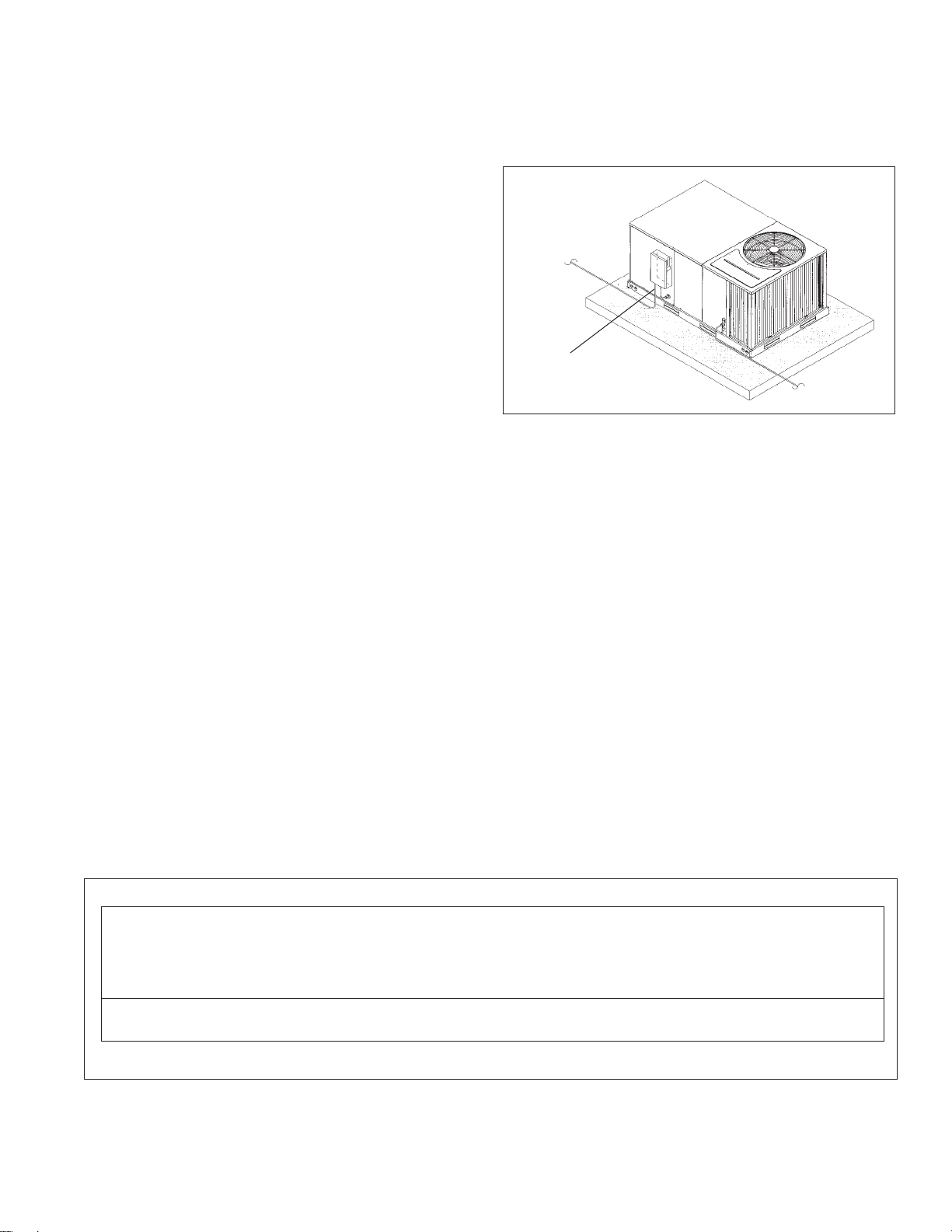
2 Install a branch circuit disconnect within sight of the unit
and of adequate size to handle the starting current.
Reference Figure 12 for proper location.
3 For branch circuit wiring (main power supply to unit dis-
connect), the minimum wire size can be determined from
Table A using the circuit ampacity found on the unit
nameplate.
4 This unit incorporates single point electrical connection
for unit and electric heat accessory.
5 Power wiring must be run in grounded rain-tight conduit.
Connect the power field wiring as follows:
a NO ELECTRIC HEAT - Connect the field wires
directly to the contactor pigtail in the electric heat
access area. Connect ground wire to ground lug.
b WITH ELECTRIC HEAT - Connect the field wires to
the terminal block on the electric heater kit in the electric heat access area. Connect the ground wire to the
ground lug on the heater kit.
NOTE: For field installation of a heater kit, follow the instructions
provided with the heater kit.
6 The pigtail wires in the electric heat access area are facto-
ry wired to the contactor in the control box.
7 DO NOT connect aluminum field wires to electric heat
kit power input terminals.
WARRANTY WILL BE VOIDED IF CONNECTIONS ARE
NOT MADE PER INSTRUCTIONS
Control Wiring (Class II)
1 Low voltage wiring should not be run in conduit with
power wiring.
2 Control wiring is routed through the 7/8" hole adjacent to
the compressor access panel. See Figure 2. Use a minimum #18 AWG thermostat wire. For wire lengths
exceeding 50', use #16 AWG thermostat wire. The low
voltage wires are connected to the unit pigtails which are
supplied with the unit in the low voltage connection box
located below the unit control box.
3 Figure 14 shows representative low voltage connection
diagrams. Read your thermostat installation instructions
for any special requirements for your specific thermostat.
NOTE: Units installed in Canada require that an outdoor
thermostat (30,000 min. cycles of endurance) be installed
and be wired with C.E.C. Class I wiring.
COPPER WIRE SIZE — AWG (1% VOLTAGE DROP)
300
250
200
150
100
50
Supply
Wire
Length
Feet
Circuit Ampacity
NOTE:
1. Wire size based on 60ºC type copper conductors below 100 ampacity. 2. Wire size based on 75ºC type copper conductors for 100 ampacity and above.
4
4
6
8
10
14
15
3
4
4
6
8
12
20
2
3
4
6
8
10
25
2
3
4
4
6
10
30
1
2
3
4
6
8
35
1/0
1
2
4
6
8
40
1/0
1
2
3
4
6
45
2/0
1/0
1
3
4
6
50
2/0
1/0
1
2
4
6
55
3/0
2/0
1/0
2
3
4
60
3/0
2/0
1/0
1
3
4
65
3/0
2/0
1/0
1
2
4
70
4/0
3/0
2/0
1/0
2
3
75
4/0
3/0
2/0
1/0
2
3
80
4/0
3/0
2/0
1/0
1
3
85
4/0
4/0
3/0
1/0
1
2
90
250
4/0
3/0
2/0
1
2
95
250
4/0
3/0
2/0
1
2
100
250
4/0
3/0
2/0
1
2
105
250
4/0
3/0
2/0
1/0
2
110
300
250
4/0
2/0
1/0
1
115
300
250
4/0
3/0
1/0
1
120
300
250
4/0
3/0
1/0
1
125
300
250
4/0
3/0
1/0
1
130
300
250
4/0
3/0
1/0
1/0
135
350
350
300
4/0
1/0
1/0
140
350
350
300
4/0
2/0
1/0
145
350
350
300
4/0
2/0
1/0
150
350
350
300
4/0
2/0
2/0
155
Table A
Figure 12: Recommended location of branch circuit
disconnect
TO POWER
BRANCH CIRCUIT DISCONNECT
TO CONTROL
Page 10
10 IM 864
Internal Wiring
IMPORTANT: Some single phase models are equipped with a
single pole contactor. Caution must be exercised when servicing
as only one leg of the power supply is broken with the contactor.
Some models are equipped with electronically commutated blower motors which are constantly energized unless the main unit
disconnect is in the off position.
1 A diagram of the internal wiring of this unit is located on
the inside of the compressor access panel. If any of the
original wire as supplied with the unit must be replaced,
the wire gauge and insulation must be the same as original wiring.
208 Volt Applications
Transformer is factory-wired for 220 volts on 200/220 volt
models and must be changed for 200-volt applications. See
unit wiring diagram for 200-volt wiring.
Grounding
Thermostat
The thermostat should be mounted on an inside wall about
five feet above the floor in a location where it will not be
affected by unconditioned air, sun, or drafts from open doors
or other sources. READ installation instructions in thermostat
package CAREFULLY because each has some different
wiring requirements. The low voltage wiring should be sized
as shown in Table B.
Install the room thermostat in accordance with the instruction
sheet packed in the box with the thermostat.
Indoor Air Flow Data
Direct-drive blower models are shipped factory wired for the
proper speed at a typical external static. See Blower
Performance Data. Belt-drive blower models have motor
sheaves set for proper CFM at a typical external static.
Crankcase Heat (Optional)
Crankcase heat is not required on scroll type compressors, but
may be necessary for difficult starting situations.
Pre-Start Check
1 Is unit properly located and slightly slanted toward
indoor condensate drain?
2 Is ductwork insulated, weatherproofed, with proper
spacing to combustible materials?
3 Is air free to travel to and from outdoor coil? (See Figure
5.)
4 Is the wiring correct, tight, and according to unit wiring
diagram?
5 Is unit grounded?
6 Are field supplied air filters in place and clean?
7 Do the outdoor fan and indoor blower turn freely with-
out rubbing, and are they tight on the motor shafts?
8 Are the compressor shipping supports removed (if so
equipped)?
Startup
1 Turn thermostat to “OFF,” turn “on” power supply at
disconnect switch.
2 Turn temperature setting as high as it will go.
3 Turn fan switch to “ON.”
4 Indoor blower should run. Be sure it is running in the
right direction.
5 Turn fan switch to “AUTO.” Turn system switch to
“COOL” and turn temperature setting below room temperature. Unit should run in cooling mode.
6 Is outdoor fan operating correctly in the right direction?
ILL I312
Figure 13: Heater Kit Installation
The unit must be permanently grounded. A grounding lug is
provided in the electric heat kit access area for a ground
wire. Failure to ground this unit can result in fire or electrical
shock causing property damage, severe personal injury or
death.
▲▲
DANGER
!
Table B
FIELD WIRE SIZE FOR 24 VOLT THERMOSTAT CIRCUITS
SOLID COPPER WIRE - AWG.
3.0 16 14 12 10 10 10
2.5 16 14 12 12 12 10
2.0 18 16 14 12 12 10
50 100 150 200 250 300
Length of Run – Feet (1)
Thermostat Load -
Amps
(1) The total wire length is the distance from the furnace to the thermostat and back to the furnace.
NOTE: DO NOT USE CONTROL WIRING SMALLER THAN NO. 18
AWG.
Page 11

11IM 864
7 Is compressor running correctly.
8 Check the refrigerant charge using the instructions locat-
ed on compressor access panel. Replace service port
caps. Service port cores are for system access only and
will leak if not tightly capped.
9 Turn thermostat system switch to proper mode “HEAT”
or “COOL” and set thermostat to proper temperature setting. Record the following after the unit has run some
time.
a Operating Mode______________________________
b Discharge Pressure (High) _________________PSIG
c Vapor Pressure at Compressor (Low)_________PSIG
d VaporLine Temperature at Compressor _________°F.
e Indoor Dry Bulb ___________________________°F.
f Indoor Wet Bulb ___________________________°F.
g Outdoor Dry Bulb __________________________°F.
h Outdoor Wet Bulb__________________________°F.
i Voltage at Contactor ______________________Volts
j Current at Contactor______________________Amps
k Model Number_______________________________
l Serial Number _______________________________
m Location ____________________________________
n Owner _____________________________________
o Date _______________________________________
10 Adjust discharge air grilles and balance system.
11 Check ducts for condensation and air leaks.
12 Check unit for tubing and sheet metal rattles.
13 Instruct the owner on operation and maintenance.
14 Leave “INSTALLATION” and ”USE AND CARE“ instruc-
tions with owner.
Operation
Most single phase units are operated PSC (no start relay or
start capacitor). It is important that such systems be off for a
minimum of 5 minutes before restarting to allow equalization
of pressures. The thermostat should not be moved to cycle unit
without waiting five minutes. To do so may cause the compressor to stop on an automatic open overload device or blow
a fuse. Poor electrical service can cause nuisance tripping in
overloads or blow fuses.
IMPORTANT: The compressor has an internal overload protector. Under some conditions, it can take up to 2 hours for this
overload to reset. Make sure overload has had time to reset
before condemning the compressor.
Some units are equipped with a time delay control (TDC1).
The control allows the blower to operate for up to 60 seconds
after the thermostat is satisfied.
Figure 14: Low Voltage Connections Diagrams
STANDARD CONTROL WIRING
R
W
G
Y
Y2
C
RED
BLACK
GRAY
YELLOW
ORANGE
BROWN
THERMOSTAT
SUB-BASE
UNIT CONTROLS
WIRE PIGTAILS
NOTE: Y2 IS ONLY USED WITH OPTIONAL ECONOMIZER.
Page 12

12 IM 864
Auxiliary Heat
Control System Operation
1 In the cooling mode, the thermostat will, on a call for
cooling, energize the compressor contactor and the indoor
blower relay. The indoor blower can be operated continuously by setting the thermostat fan switch at the “ON”
position.
2 In the heating mode, the thermostat will energize one or
more supplementary resistance heaters.
Replacement Parts
To find your local McQuay Certified Parts Distributor, go to
www.mcquay.com and select Parts Locator.
Charge Information
Refer to the appropriate charge chart included in this manual.
Troubleshooting
Refer to the troubleshooting chart included in this manual.
Wiring Diagrams
Refer to the appropriate wiring diagram included in this manual.
Only electric heater kits supplied by this manufacturer as
described in this publication have been designed, tested,
and evaluated by a nationally recognized safety testing
agency for use with this unit. Use of any other manufactured
electric heaters installed within this unit may cause hazardous conditions resulting in property damage, fire, bodily
injury or death.
▲▲
DANGER
!
Page 13

13IM 864IM 864
General Data
Nominal Sizes 3-5 Tons [10.6-17.6 kW] ASHRAE 90.1-2004 Compliant Models
McQuay MPS Series 003AYCK 003AYDK 004AYCK 004AYDK
Cooling Performance
1
Gross Cooling Capacity Btu [kW] 37,400 [10.96] 37,400 [10.96] 49,000 [14.36] 49,000 [14.36]
EER/SEER
2
11.7/13 11.7/13 11.4/13.1
Nominal CFM/ARI Rated CFM [L/s] 1200/1200 [566/566] 1200/1200 [566/566] 1600/1550 [755/731] 1600/1550 [755/731]
ARI Net Cooling Capacity Btu [kW] 36,000 [10.55] 36,000 [10.55] 47,000 [13.77] 47,000 [13.77]
Net Sensible Capacity Btu [kW] 26,400 [7.74] 26,400 [7.74] 33,600 [9.84] 33,600 [9.84]
Net System Power kW 3.08 3.08 4.15 4.15
Net Weight lbs. [kg] 543 [246] 543 [246] 580 [263] 580 [263]
Compressor
No./Type 1/Scroll 1/Scroll 1/Scroll 1/Scroll
Outdoor Sound Rating (dB)
4
78 78 78 78
Outdoor Coil—Fin Type Louvered Louvered Louvered Louvered
Tube Type Rifled Rifled Rifled Rifled
Tube Size in. [mm] OD 0.375 [9.5] 0.375 [9.5] 0.375 [9.5] 0.375 [9.5]
Face Area sq. ft. [sq. m] 16.91 [1.57] 16.91 [1.57] 16.56 [1.54] 16.56 [1.54]
Rows / FPI [FPcm] 1 / 22 [9] 1 / 22 [9] 2 / 22 [9] 2 / 22 [9]
Net Latent Capacity Btu [kW] 9,600 [2.81] 9,600 [2.81] 13,400 [3.93] 13,400 [3.93]
Indoor Coil—Fin Type Corrugated Corrugated Corrugated Corrugated
Tube Type Rifled Rifled Rifled Rifled
Tube Size in. [mm] 0.375 [9.5] 0.375 [9.5] 0.375 [9.5] 0.375 [9.5]
Face Area sq. ft. [sq. m] 5.17 [0.48] 5.17 [0.48] 5.17 [0.48] 5.17 [0.48]
Rows / FPI [FPcm] 2 / 17 [7] 2 / 17 [7] 3 / 15 [6] 3 / 15 [6]
Refrigerant Control TX Valves TX Valves TX Valves TX Valves
Drain Connection No./Size in. [mm] 1/0.75 [19.05] 1/0.75 [19.05] 1/0.75 [19.05] 1/0.75 [19.05]
Outdoor Fan—Type Propeller Propeller Propeller Propeller
No. Used/Diameter in. [mm] 1/24 [609.6] 1/24 [609.6] 1/24 [609.6] 1/24 [609.6]
Drive Type/No. Speeds Direct/1 Direct/1 Direct/1 Direct/1
CFM [L/s] 3680 [1737] 3680 [1737] 3680 [1737] 3680 [1737]
No. Motors/HP 1 at 1/3 HP 1 at 1/3 HP 1 at 1/3 HP 1 at 1/3 HP
Motor RPM 1075 1075 1075 1075
Indoor Fan—Type FC Centrifugal FC Centrifugal FC Centrifugal FC Centrifugal
No. Used/Diameter in. [mm] 1/10x10 [254x254] 1/10x10 [254x254] 1/10x10 [254x254] 1/10x10 [254x254]
Drive Type/No. Speeds Direct/3 Direct/3 Direct/3 Belt/Variable
No. Motors 1 1 1 1
Motor HP 1/2 1/2 1/2 1/2
Motor RPM 1075 1075 1075 1725
Motor Frame Size 48 48 48 48
Filter—Type Disposable Disposable Disposable Disposable
Furnished Yes Yes Yes Yes
(No.) Size Recommended in. [mm] (1)1x16x25 [25x406x635] (1)1x16x25 [25x406x635] (1)1x16x25 [25x406x635] (1)1x16x25 [25x406x635]
Refrigerant Charge Oz. [g] 93 [2637] 93 [2637] 167 [4734] 167 [4734]
Weights
Ship Weight lbs. [kg] 550 [249] 550 [249] 587 [266] 587 [266]
11.4/13.1
(1)1x16x25 [25x406x635] (1)1x16x25 [25x406x635] (1)1x16x25 [25x406x635] (1)1x16x25 [25x406x635]
CONTINUED
[] Designates Metric Conversions
NOTES:
1. Cooling Performance is rated at 95° F ambient, 80° F entering dry bulb, 67° F entering wet bulb. Gross capacity does
not include the effect of fan motor heat. ARI capacity is net and includes the effect of fan motor heat. Units are suitable
for operation to 20% of nominal cfm. Units are certified in accordance with the Unitary Air Conditioner Equipment
certification program, which is based on ARI Standard 210/240 or 360.
2. EER and/or SEER are rated at ARI conditions
and in accordance with DOE test procedures.
3. Integrated Part Load Value is rated in accordance with ARI Standard 210/240 or 360. Units are rated at 80° F ambient,
80° F entering dry bulb, and 67° F entering wet bulb at ARI rated cfm.
4. Outdoor Sound Rating shown is tested in accordance with ARI Standard 270.
Page 14

IM 86414
General Data
Nominal Sizes 3-5 Tons [10.6-17.6 kW] ASHRAE 90.1-2004 Compliant Models
McQuay MPS Series 005AYCM 005AYDM
Cooling Performance
1
Gross Cooling Capacity Btu [kW] 60,000 [17.58] 60,000 [17.58]
EER/SEER
2
11.6/13 11.6/13
Nominal CFM/ARI Rated CFM [L/s] 2000/1900 [897/897] 2000/1900 [897/897]
ARI Net Cooling Capacity Btu [kW] 58,000 [16.99] 58,000 [16.99]
Net Sensible Capacity Btu [kW] 42,000 [12.31] 42,000 [12.31]
Net System Power kW 5 5
Net Weight lbs. [kg] 590 [268] 590 [268]
Compressor
No./Type 1/Scroll 1/Scroll
Outdoor Sound Rating (dB)
4
83 83
Outdoor Coil—Fin Type Louvered Louvered
Tube Type Rifled Rifled
Tube Size in. [mm] OD 0.375 [9.5] 0.375 [9.5]
Face Area sq. ft. [sq. m] 16.56 [1.54] 16.56 [1.54]
Rows / FPI [FPcm] 2 / 22 [9] 2 / 22 [9]
Net Latent Capacity Btu [kW] 16,000 [4.69] 16,000 [4.69]
Indoor Coil—Fin Type Corrugated Corrugated
Tube Type Rifled Rifled
Tube Size in. [mm] 0.375 [9.5] 0.375 [9.5]
Face Area sq. ft. [sq. m] 5.17 [0.48] 5.17 [0.48]
Rows / FPI [FPcm] 3 / 15 [6] 3 / 15 [6]
Refrigerant Control TX Valves TX Valves
Drain Connection No./Size in. [mm] 1/0.75 [19.05] 1/0.75 [19.05]
Outdoor Fan—Type Propeller Propeller
No. Used/Diameter in. [mm] 1/24 [609.6] 1/24 [609.6]
Drive Type/No. Speeds Direct/1 Direct/1
CFM [L/s] 3930 [1855] 3930 [1855]
No. Motors/HP 1 at 1/3 HP 1 at 1/3 HP
Motor RPM 1075 1075
Indoor Fan—Type FC Centrifugal FC Centrifugal
No. Used/Diameter in. [mm] 1/10x10 [254x254] 1/10x10 [254x254]
Drive Type/No. Speeds Belt/Variable Belt/Variable
No. Motors 1 1
Motor HP 1 1
Motor RPM 1725 1725
Motor Frame Size 56 56
Filter—Type Disposable Disposable
Furnished Yes Yes
(No.) Size Recommended in. [mm] (1)1x16x25 [25x406x635] (1)1x16x25 [25x406x635]
Refrigerant Charge Oz. (Sys. 1/Sys. 2) [g] 160 [4536] 160 [4536]
Weights
Ship Weight lbs. [kg] 597 [271] 597 [271]
(1)1x16x25 [25x406x635] (1)1x16x25 [25x406x635]
[] Designates Metric Conversions
NOTES:
1. Cooling Performance is rated at 95° F ambient, 80° F entering dry bulb, 67° F entering wet bulb. Gross capacity does
not include the effect of fan motor heat. ARI capacity is net and includes the effect of fan motor heat. Units are suitable
for operation to 20% of nominal cfm. Units are certified in accordance with the Unitary Air Conditioner Equipment
certification program, which is based on ARI Standard 210/240 or 360.
2. EER and/or SEER are rated at ARI conditions
and in accordance with DOE test procedures.
3. Integrated Part Load Value is rated in accordance with ARI Standard 210/240 or 360. Units are rated at 80° F ambient,
80° F entering dry bulb, and 67° F entering wet bulb at ARI rated cfm.
4. Outdoor Sound Rating shown is tested in accordance with ARI Standard 270.
Page 15

15
Miscellaneous
ELECTRICAL DATA
Minimum Circuit Ampacity 18/18
Unit Information
Unit Operating
Voltage Range
187-253
Minimum Overcurrent
Protection Device Size
20/20
Maximum Overcurrent
Protection Device Size
25/25
Compressor Motor
No. 1
Volts 208/230
Phase 3
HP 3
RPM 3450
Amps (RLA) 9.6/9.6
Amps (LRA) 73/73
Condenser Motor
No. 1
Volts 208/230
Phase 1
HP 1/3
Amps (FLA) 1.5
Amps (LRA) 3
Evaporator Fan
No. 1
Volts 208/230
Phase 1
HP 1/2
Amps (FLA) 4
Amps (LRA) 6.7 3.6
2
1/2
1
460
1
1.9
1
1/3
1
460
1
38
5.8
3450
3
3
460
1
15
15
11
414-506
6.7
4
1/2
1
208/230
1
3
1.5
1/3
1
208/230
1
80.8/80.8
12.2/12.2
3450
4
3
208/230
1
30/30
25/25
21/21
187-253
3.6
2
1/2
1
460
1
1.9
1
1/3
1
460
1
41
6.1
3450
4
3
460
1
15
15
11
414-506
24
3.8
1
3
208/230
1
4.9
2.2
1/3
1
208/230
1
110/110
15.4/15.4
3450
5
3
208/230
1
40/40
30/30
26/26
187-253
12
1.9
1
3
460
1
1.9
1
1/3
1
460
1
52
7.1
3450
5
3
460
1
15
15
12
414-506
003AYCK 003AYDK 004AYCK 004AYDK 005AYCM 005AYDM
1. Horsepower Per Compressor.
2. Amp Draw Per Motor. Multiply Value By Number of Motors to Determine Total Amps.
IM 864
Page 16

16 IM 864
INDOOR AIRFLOW PERFORMANCE FOR 3-4 TON PACKAGED ROOFTOP SYSTEM
DIRECT DRIVE
0.10 0.20 0.30 0.40 0.50 0.60 0.70 0.80
CFM 1210 1193 1175 1155 1125 1075 1015 925
Watts 450 400 395 385 380 375 370 360
CFM 1515 1500 1475 1450 1405 1350 1275 1180
Watts 525 515 510 505 490 475 460 445
CFM 1680 1650 1625 15801530 1460 1390 1280
Watts 650 640 630 610 580 560 545 515
CFM 1210 1193 1175 1155 1125 1075 1015 925
Watts 450 400 395 385 380 375 370 360
CFM 1515 1500 1475 1450 1405 1350 1275 1180
Watts 525 515 510 505 490 475 460 445
CFM 1680 1650 1625 15801530 1460 1390 1280
Watts 650 640 630 610 580 560 545 515
DIRECT-DRIVE BLOWER 208 AIRFLOW PERFORMANCE - 3 & 4 TONS
CFM Air Delivery/RPM/Watts-208 VOLTS
External Static Pressure-Inches W.C.
Unit Model
MPS003A
MPS004A
Cool
Low
Med
Heat
Low
Motor Speed
From Factory
Heating
Input
BTU/hr
[kW]
[06]
[10]
[12]
[15]
[20]
Manufacturer
Recommended
Air-Flow Range
(Min / Max) CFM
1050 / 1350
Blower Size/
Motor HP #
of Speeds
10x10
1/2
3 Speed
Motor
Speed
Low
Med
High
Med
[06]
[10]
[12]
[15]
[20]
1400 / 1800
10x10
1/2
3 Speed
Low
Med
High
Page 17

17IM 864
INDOOR AIRFLOW PERFORMANCE FOR 3-4 TON PACKAGED ROOFTOP SYSTEM
DIRECT DRIVE
0.10 0.20 0.30 0.40 0.50 0.60 0.70 0.80
CFM 1400 1375 1360 13351305 1255 1210 1100
Watts 470 460 455 450 440 435 425 410
CFM 1685 1620 1580 1550 1500 14301350 1230
Watts 635 600 580 570 550 535 505 475
CFM 1870 1830 1790 1730 1660 1580 1500 1375
Watts 780 760 740 700 660 635 600 555
CFM 1400 1375 1360 13351305 1255 1210 1100
Watts 470 460 455 450 440 435 425 410
CFM 1685 1620 1580 1550 1500 14301350 1230
Watts 635 600 580 570 550 535 505 475
CFM 1870 1830 1790 1730 1660 1580 1500 1375
Watts 780 760 740 700 660 635 600 555
DIRECT-DRIVE 230 AIRFLOW PERFORMANCE - 3 & 4 TONS
CFM Air Delivery/RPM/Watts-230 VOLTS
External Static Pressure-Inches W.C.
Unit Model
MPS003A
MPS004A
Cool
Low
Med
Heat
Low
Motor Speed
From Factory
Heating
Input
BTU/hr
[kW]
[06]
[10]
[12]
[15]
[20]
Manufacturer
Recommended
Air-Flow Range
(Min / Max) CFM
1050 / 1350
Blower Size/
Motor HP #
of Speeds
10x10
1/2
3 Speed
Motor
Speed
Low
Med
High
Med
[06]
[10]
[12]
[15]
[20]
1400 / 1800
10x10
1/2
3 Speed
Low
Med
High
Page 18

18 IM 864
INDOOR AIRFLOW PERFORMANCE FOR 3-4 TON PACKAGED ROOFTOP SYSTEM
DIRECT DRIVE
0.10 0.20 0.30 0.40 0.50 0.60 0.70 0.80
CFM 1400 1375 1360 13351305 1255 1210 1100
Watts 470 460 455 450 440 435 425 410
CFM 1685 1620 1580 1550 1500 14301350 1230
Watts 635 600 580 570 550 535 505 475
CFM 1870 1830 1790 1730 1660 1580 1500 1375
Watts 780 760 740 700 660 635 600 555
CFM 1400 1375 1360 13351305 1255 1210 1100
Watts 470 460 455 450 440 435 425 410
CFM 1685 1620 1580 1550 1500 14301350 1230
Watts 635 600 580 570 550 535 505 475
CFM 1870 1830 1790 1730 1660 1580 1500 1375
Watts 780 760 740 700 660 635 600 555
DIRECT-DRIVE 460 AIRFLOW PERFORMANCE - 3 & 4 TONS
CFM Air Delivery/RPM/Watts-460 VOLTS
External Static Pressure-Inches W.C.
Unit Model
MPS003A
MPS004A
Cool
Low
Med
Heat
Low
Motor Speed
From Factory
Heating
Input
BTU/hr
[kW]
[06]
[10]
[12]
[15]
[20]
Manufacturer
Recommended
Air-Flow Range
(Min / Max) CFM
1050 / 1350
Blower Size/
Motor HP #
of Speeds
10x10
1/2
3 Speed
Motor
Speed
Low
Med
High
Med
[06]
[10]
[12]
[15]
[20]
1400 / 1800
10x10
1/2
3 Speed
Low
Med
High
Page 19

19IM 864
INDOOR AIRFLOW PERFORMANCE FOR 5 TON PACKAGED ROOFTOP SYSTEM
BELT DRIVE
“M”
“
L”
RPM
———
—
780
800
830
860
895
940
970
WATTS
———
—
455
485
550
615
680
755
825
RPM
—
—
780
795
815
850
880
915
945
975
1015
WATTS
—
—
390
450
470
530
605
655
735
795
880
RPM
780
795
805
840
870
895
930
955
995
1015
1040
WATTS
370
405
425
490
540
590
655
705
780
830
925
RPM
815
840
870
895
915
945
970
1005
1030
1065
1100
WATTS
385
415
470
530
540
640
700
760
830
910
1005
RPM
875
895
915
940
965
995
1015
1040
1060
1100
1145
WATTS
425
440
510
570
675
675
730
820
880
965
1055
RPM
930
945
965
990
1010
1035
1055
1090
1120
1150
1175
WATTS
460
500
560
605
660
720
790
870
940
1025
1085
RPM
970
995
1015
1035
1055
1070
1105
1130
1155
1180
1225
WATTS
490
540
600
640
710
775
830
910
980
1050
1140
RPM
1030
1045
1060
1075
1100
1120
1145
1170
1195
1225
1260
WATTS
540
595
640
680
760
810
875
950
1020
1095
1175
RPM
1065
1080
1105
1120
1140
1160
1180
1210
1240
1265
1300
WATTS
570
615
680
725
785
850
910
995
1055
1125
1210
RPM
1105
1135
1145
1160
1175
1200
1225
1250
1275
1310
1340
WATTS
595
650
705
755
810
890
950
1020
1100
1175
1255
RPM
1150
1165
1180
1200
1225
1245
1260
1290
1320
1350
1370
WATTS
615
675
730
790
850
915
980
1060
1140
1230
1315
RPM
1195
1215
1225
1245
1260
1290
1320
1335
1360
1375
1400
WATTS
645
700
750
815
880
960
1035
1100
1180
1260
1375
RPM
1235
1255
1275
1300
1320
1335
1350
1370
1385
1405
—
WATTS
660
735
790
855
930
1000
1075
1150
1225
1320
—
RPM
1300
1320
1340
1355
1365
1375
1385
1400
———
WATTS
705
775
840
905
985
1050
1120
1200
———
RPM
1340
1355
1365
1375
1390
1405
—————
WATTS
745
805
880
940
1020
1100
—————
0.1 0.2 0.3 0.4 0.5 0.6 0.7 0.8 0.9 1.0 1.10 1.20 1.30 1.40 1.50
EXTERNAL STATIC PRESSURE–INCHES OF WATER
VOLTAGE 208-230, 460 - 3 PHASE
CAPACITY 5 TON PACKAGED AIR CONDITIONER (13 SEER)
AIR
FLOW
CFM
1400
1500
1600
1700
1800
1900
2000
2100
2200
2300
2400
DRIVE PACKAGE “L” “M”
MOTOR H.P. 3/4 1
BLOWER SHEAVE 6.4 PITCH DIAMETER 6.4 PITCH DIAMETER
MOTOR SHEAVE 2.8-3.8 PITCH DIAMETER - ADJ. 3.4-4.4 PITCH DIAMETER - ADJ.
TURNS OPEN 0 1 2 3 45 60123 456
RPM 1095 1040 995 940 890 835780 1405 1360 1305 1250 1195 1145 1095
BELT DRIVE AIRFLOW PERFORMANCE - 5 TON
NOTE: L-drive left of bold line, M-drive right of bold line.
NOTE: Factory sheave settings are shown in bold print.
Page 20

20 IM 864
AUXILIARY HEATER KITS CHARACTERISTICS AND APPLICATION
208-240 VOLT, THREE PHASE, 60 HZ, AUXILIARY ELECTRIC HEATER KITS CHARACTERISTICS AND APPLICATION
Single Power Supply For Both Unit And Heater Kit
Separate Power Supply For Both Unit And Heater Kit
Model
No.
MPS
Heater Kit
Nominal kW
Rated Heater
kW @
208-240 V
Heater
KBTU/Hr @
208-240 V
Heater
Amp. @
208-240 V
Unit Min. Ckt
Ampacity @
208-240V
Min/Max @
208 V
Min/Max @
240 V
Over Current
Protective Device Size
Heater Kit
Min. Ckt.
Ampacity
Heater Kit
Max. Fuse
Size
Air
Conditioner
Min. Ckt.
Ampacity
208-240 V
Min/Max @
208 V
Min/Max @
240 V
Air Conditioner Over
Current Protective
Device Size
No Heat - - - 18/18 20/25 20/25 - - 18/18 20/25 20/25
A06C+ 4.2/5.6 14.33/19.10 11.7/13.5 20/22 20/20 20/25 15/17 15/20 - - -
A10C+ 7.2/9.6 24.56/32.75 20.0/23.1 31/34 35/35 35/35 25/29 25/30- - -
*A11C+ 7.2/9.6 24.56/32.75 20.0/23.1 31/
34 35/35 35/35 25/29 25/30- - -
A12C+ 8.4/11.2 28.66/38.21 23.4/27.0 35/39 35/35 40/40 30/34 30/35- - -
A15C+ 10.8/14.4 36.84/49.1330.1/34.7 43/49 45/45 50/50 38/44 40/45 - - -
A20C+ 14.4/19.2 49.13/65.51 40.1/46.2 56/63 60/60 70/70 50/58 50/60 - - -
*A21C+ 14.4/19.2 49.13/65.51 40.1/46.2 56/63 60/60 70/70 50/58 50/60 - - -
No Heat - - - 21/21 25/30 25/30 - - 21/21 25/30 25/30
A06C+ 4.2/5.6 14.33/19.10 11.7/13.5 20/22 25/30 25/30 15/17 15/20 - - -
A10C+ 7.2/9.6 24.56/32.75 20.0/23.1 31/34 35/35 35/35 25/29 25/
30- - -
*A11C+ 7.2/9.6 24.56/32.75 20.0/23.1 31/34 35/35 35/35 25/29 25/30- - -
A12C+ 8.4/11.2 28.66/38.21 23.4/27.0 35/39 35/35 40/40 30/34 30/35- - -
A15C+ 10.8/14.4 36.84/49.1330.1/34.7 43/49 45/45 50/50 38/44 40/45 - - -
A20C+ 14.4/19.2 49.13/65.51 40.1/46.2 56/63 60/60 70/70 50/58 50/60 - - -
*A21C+ 14.4/19.2 49.13/65.51 40.1/46.2 56/63 60/60 70/70 50/58 50/60 - - -
003AYCK
004AYCK
* = For Canadian use only. Uses “P” fuses for inductive circuit
+ = Field Installed Only
Page 21

21IM 864
AUXILIARY HEATER KITS CHARACTERISTICS AND APPLICATION
Model
No.
MPS
Heater Kit
Nominal kW
208-240 VOLT, THREE PHASE, 60 HZ, AUXILIARY ELECTRIC HEATER KITS CHARACTERISTICS AND APPLICATION
Single Power Supply For Both Unit And Heater Kit
Separate Power Supply For Both Unit And Heater Kit
Rated Heater
kW @
208-240 V
Heater
KBTU/Hr @
208-240 V
Heater
Amp. @
208-240 V
Unit Min. Ckt
Ampacity @
208-240V
Min/Max @
208 V
Min/Max @
240 V
Over Current
Protective Device Size
Heater Kit
Min. Ckt.
Ampacity
Heater Kit
Max. Fuse
Size
Air
Conditioner
Min. Ckt.
Ampacity
208-240 V
Min/Max @
208 V
Min/Max @
240 V
Air Conditioner Over
Current Protective
Device Size
No Heat - - - 26/26 30/40 30/40 - - 26/26 30/40 30/40
A06C+ 4.2/5.6 14.33/19.10 11.7/13.5 26/26 30/40 30/40 15/17 15/20
A10C+ 7.2/9.6 24.56/32.75 20.0/23.1 30/34 30/40 30/40 25/29 25/30
*A11C+ 7.2/9.6 24.56/32.75 20.0/23.1 30/34 30/40 30/40 25/29 25/
30
A12C+ 8.4/11.2 28.66/38.21 23.4/27.0 35/39 35/40 30/40 30/34 30/35
A15C 10.8/14.4 36.84/49.1330.1/34.7 43/49 45/45 50/50 38/44 40/45
A20C+ 14.4/19.2 49.13/65.51 40.1/46.2 55/63 60/60 70/70 50/58 50/60 - - -
*A21C+ 14.4/19.2 49.13/65.51 40.1/46.2 55/63 60/60 70/70 50/58 50/60 - - -
A24C+ 18.0/24.0 61.41/81.88 50.1/57.8 68/78 70/70 80/80 50/58 50/60 - - -
005AYCM
* = For Canadian use only. Uses “P” fuses for inductive circuit
+ = Field Installed Only
Page 22

22 IM 864
AUXILIARY HEATER KITS CHARACTERISTICS AND APPLICATION
460 VOLT, THREE PHASE, 60 HZ, AUXILIARY ELECTRIC HEATER KITS CHARACTERISTICS AND APPLICATION
Single Power Supply For Both Unit And Heater Kit
Separate Power Supply For Both Unit And Heater Kit
Model
No.
MPS
Heater Kit
Nominal kW
Rated Heater
kW @ 480 V
Heater
KBTU/Hr @
480 V
Heater
Amp. @
480 V
Unit Min. Ckt
Ampacity @
480 V
Min/Max @
480 V
Min/Max @
480 V
Over Current
Protective Device Size
Heater Kit
Min. Ckt.
Ampacity
Heater Kit
Max. Fuse
Size
Air
Conditioner
Min. Ckt.
Ampacity 480
Min/Max @
480 V
Min/Max @
480 V
Air Conditioner Over
Current Protective
Device Size
No Heat - - - 10 15 15 - - 10 15 15
A06D+ 5.6 19.10 6.7 11 15 15 9 15
A10D+ 9.6 32.75 11.6 17 20 20 15 15
*A11D+ 9.6 32.75 11.6 17 20 20 15 15
A12D+ 11.2 38.21 13.5 19 20 20 17 20
A15D+ 14.4 49.13 17.3 24 25 25 22 25
A20D+ 19.2 65.51 23.1 31 35 35 30 30---
*A21D+ 19.2 65.51 23.1 31 35 3
52930---
No Heat - - - 11 15 15 - - 11 15 15
A06D+ 5.6 19.10 6.7 11 15 15 9 15
A10D+ 9.6 32.75 11.6 17 20 20 15 15
*A11D+ 9.6 32.75 11.6 17 20 20 15 15
A12D+ 11.2 38.21 13.5 19 20 20 17 20
A15D+ 14.4 49.13 17.3 24 25 25 22 25 - - -
A20D+ 19.2 65.51 23.1 31 35 35 30 30---
*A21D+ 19.2 65.51 23.1 31 35 352930---
003AYDK
004AYDK
* = For Canadian use only. Uses “P” fuses for inductive circuit
+ = Field Installed Only
Page 23

23IM 864
AUXILIARY HEATER KITS CHARACTERISTICS AND APPLICATION
460 VOLT, THREE PHASE, 60 HZ, AUXILIARY ELECTRIC HEATER KITS CHARACTERISTICS AND APPLICATION
Single Power Supply For Both Unit And Heater Kit
Separate Power Supply For Both Unit And Heater Kit
Model
No.
MPS
Heater Kit
Nominal kW
Rated Heater
kW @ 480 V
Heater
KBTU/Hr @
480 V
Heater
Amp. @
480 V
Unit Min. Ckt
Ampacity @
480 V
Min/Max @
480 V
Min/Max @
480 V
Over Current
Protective Device Size
Heater Kit
Min. Ckt.
Ampacity
Heater Kit
Max. Fuse
Size
Air
Conditioner
Min. Ckt.
Ampacity 480
Min/Max @
480 V
Min/Max @
480 V
Air Conditioner Over
Current Protective
Device Size
No Heat - - - 12 15 15 - - 12 15 15
A06D+ 5.6 19.10 6.7 12 15 15 9 15
A10D+ 9.6 32.75 11.6 17 20 20 15 15
*A11D+ 9.6 32.75 11.6 17 20 20 15 15
A12D+ 11.2 38.21 13.5 19 20 20 17 20
A15D+ 14.4 49.13 17.3 24 25 25 22 25
A20D+ 19.2 65.51 23.1 31 35 35 30 30---
*A21D+ 19.2 65.51 23.1 31 35 3
529 30---
A24D+ 24.0 81.88 28.9 394040 3740 ---
005AYDL
* = For Canadian use only. Uses “P” fuses for inductive circuit
+ = Field Installed Only
Page 24

24 IM 864
AUXILIARY HEATER KITS CHARACTERISTICS AND APPLICATION
460 VOLT, THREE PHASE, 60 HZ, AUXILIARY ELECTRIC HEATER KITS CHARACTERISTICS AND APPLICATION
Single Power Supply For Both Unit And Heater Kit
Separate Power Supply For Both Unit And Heater Kit
Model
No.
MPS
Heater Kit
Nominal kW
Rated Heater
kW @ 208-
480 V
Heater
KBTU/Hr @
480 V
Heater
Amp. @
480 V
Unit Min. Ckt
Ampacity @
480 V
Min/Max @
480 V
Min/Max @
480 V
Over Current
Protective Device Size
Heater Kit
Min. Ckt.
Ampacity
Heater Kit
Min. Ckt.
Ampacity
Air
Conditioner
Ampacity 480
Min/Max @
480 V
Min/Max @
480 V
Air Conditioner Over
Current Protective
Device Size
No Heat - - - 12 15 15 - - 12 15 15
A06D+ 5.6 19.10 6.7 12 15 15 9 15
A10D+ 9.6 32.75 11.6 17 20 20 15 15
*A11D+ 9.6 32.75 11.6 17 20 20 15 15
A12D+ 11.2 38.21 13.5 20 20 20 17 20
A15D+ 14.4 49.13 17.3 25 25 25 22 25
A20D+ 19.2 65.51 23.1 32 35 35 30 30- --
*A21D+ 19.2 65.51 23.1 32 35
3529 30- --
A24D+ 24.0 81.88 28.9 3940403740- --
005AYDM
* = For Canadian use only. Uses “P” fuses for inductive circuit
+ = Field Installed Only
Page 25

25IM 864
Figure 15: Wiring Diagram – 3 and 4 Tons
Page 26

26 IM 864
Figure 16: Wiring Diagram – 3 and 4 Tons
Page 27

IM 864
27
Figure 17: Wiring Diagram – 5 Tons
Page 28

28 IM 864
3 TON AIR CONDITIONER - 13 SEER
Page 29

29IM 864
4 TON AIR CONDITIONER - 13 SEER
Page 30

30 IM 864
5 TON AIR CONDITIONER - 13 SEER
Page 31

31IM 864
SYMPTOM POSSIBLE CAUSE REMEDY
Unit will not run • Power off or loose electrical connection • Check for correct voltage at compressor contactor in control
box
• Thermostat out of calibration-set too high • Reset
• Defective contactor • Check for 24 volts at contactor coil - replace if contacts are
open
• Blown fuses • Replace fuses
• Transformer defective • Check wiring-replace transformer
• High pressure control open (if provided) • Reset-also see high head pressure remedy-The high pressure
control opens at 450 PSIG
• Interconnecting low voltage wiring damaged • Replace thermostat wiring
Condenser fan runs, compressor • Run capacitor defective (single phase only) • Replace
doesn’t • Start relay defective (single phase on;y) • Replace
• Loose connection • Check for correct voltage at compressor check & tighten all connections
• Compressor stuck, grounded or open motor winding, • Wait at least 2 hours for overload to reset.
open internal overload. If still open, replace the compressor.
• Low voltage condition • At compressor terminals, voltage must be within 10% of rating
plate volts when unit is operating
• Low voltage condition • Add start kit components
Insufficient cooling • Improperly sized unit • Recalculate load
• Improper airflow • Check - should be approximately 400 CFM per ton.
• Incorrect refrigerant charge • Charge per procedure attached to unit service panel
• Air, non-condensibles or moisture in system • Recover refrigerant, evacuate & recharge, add filter drier
• Incorrect voltage • At compressor terminals, voltage must be within 10% of rating
plate volts when unit is operating.
Compressor short cycles • Incorrect voltage • At compressor terminals, voltage must be ±10% of
nameplate marking when unit is operating.
• Defective overload protector • Replace - check for correct voltage
• Refrigerant undercharge • Add refrigerant
Registers sweat • Low evaporator airflow • Increase speed of blower or reduce restriction - replace air
filter
High head-low vapor pressures • Restriction in liquid line, expansion device or filter drier • Remove or replace defective component
• Flow check piston size too small • Change to correct size piston
• Incorrect capillary tubes • Change coil assembly
• TXV does not open • Replace TXV
High head-high or normal vapor • Dirty condenser coil • Clean coil
pressure - Cooling mode • Refrigerant overcharge • Correct system charge
• Condenser fan not running • Repair or replace
• Air or non-condensibles in system • Recover refrigerant, evacuate & recharge
Low head-high vapor pressures • Flow check piston size too large • Change to correct size piston
• Defective Compressor valves • Replace compressor
• Incorrect capillary tubes • Replace coil assembly
Low vapor - cool compressor - • Low evaporator airflow • Increase speed of blower or reduce restriction - replace air
iced evaporator coil filter
• Operating below 65°F outdoors • Add Low Ambient Kit
• Moisture in system • Recover refrigerant - evacuate & recharge - add filter drier
• TXV limiting refrigerant flow • Replace TXV
High vapor pressure • Excessive load • Recheck load calculation
• Defective compressor • Replace
Fluctuating head & vapor • TXV hunting • Check TXV bulb clamp - check air distribution on coil - replace
pressures TXV
• Air or non-condensate in system • Recover refrigerant, evacuate & recharge
Gurgle or pulsing noise at • Air or non-condensibles in system • Recover refrigerant, evacuate & recharge
expansion device or liquid line
Trouble Shooting Chart
Disconnect all power to unit before servicing. Contactor may break only one side. Failure to shut off power can cause electrical
shock resulting in personal injury or death.
▲▲
DANGER
!
Page 32

32 IM 864
McQuay Training and Development
© 2007 McQuay International • www.mcquay.com • 800-432-1342
Now that you have made an investment in modern, efficient McQuay equipment, its care should be a high priority.
For training information on all McQuay HVAC products, please visit us at www.mcquay.com and click on training, or
call 540-248-9646 and ask for the Training Department.
Warranty
All McQuay equipment is sold pursuant to its standard terms and conditions of sale, including Limited Product
Warranty. Consult your local McQuay Representative for warranty details. Refer to Form 933-43285Y. To find your
local McQuay Representative, go to www.mcquay.com.
This document contains the most current product information as of this printing. For the most up-to-date product
information, please go to www.mcquay.com.
 Loading...