

Page 1
Installation and Maintenance Manual IM 921-1
Accessories for Maverick™ I
Commercial Packaged Rooftop Systems
Models MPS003 – 025
3 to 25 Tons
R-410A Refrigerant
Group: Applied Systems
Part Number: IM 921-1
Date: May 2010
Note: This manual is a collection of various installation manuals for accessories that may be purchased separately. To print this manual with
page numbers showing, choose “Documents and Markups” from the Adobe
© 2010 McQuay International
®
Reader® print option settings.
Page 2
INSTALLATION INSTRUCTIONS
MODELS (-)XRX-BGF03 & (-)XRX-BGF04/BGF06
ECONOMIZER POWER EXHAUST
WARN ING
This installation shall be carried out by a manufacturer's authorized representative, in accordance with the
requirements of the manufacturer. Failure to follow instructions can result in fire or explosion, causing property
damage, severe personal injury, or death. The qualified service personnel performing this work assumes
responsibility for this installation.
IM POR TANT
Damage to the product, resulting from failure to follow instructions or use of unauthorized parts, may be exclude from
the manufacturer's product warranty coverage.
WARN ING
Turn off electrical power and turn off main gas supply before beginning modification. Failure to do so can
cause electrical shock, explosion, or fire, resulting in property damage, personal injury, or death.
TOOLS RE QUIRED FOR IN STAL LA TION:
3
" electric drill with
8
1
" diameter drill bit for sheet metal.
8
5
" socket
16
(-)XRX-BGF04
PACK AGE CON TENTS
ITEM DE SCRIP TION PART No. PART No.
1 Power Exhaust Assembly 6046520 / PEA 6046508 / PEA
2 Fan Blade 6046520 / 3464 6046508 / 3464
3 Fan Motor 208-230 volt / 1 phase (C) 6046520 / 3675 6046508 / 3675
4 Fan Motor 460 volt / 1 phase (D) 6046520 / 3675 6046508 / 3675
5 Fan Motor 575 volt / 1 phase (Y) 6046520 / 3698 6046508 / 3968
6 Relay (R1) 6046520 / 3400 6046508 / 3400
7 Fuse Block 6046520 / 3370 6046508 / 3370
8 Barometric Relief Adaptor 6046520 / ADP 6046508 / ADP
(-)XRX-BGF06
Power Exhaust
C, D, Y Voltage
(-)XRX-BGF03
Power Exhaust
C, D, Y Voltage
Page 3
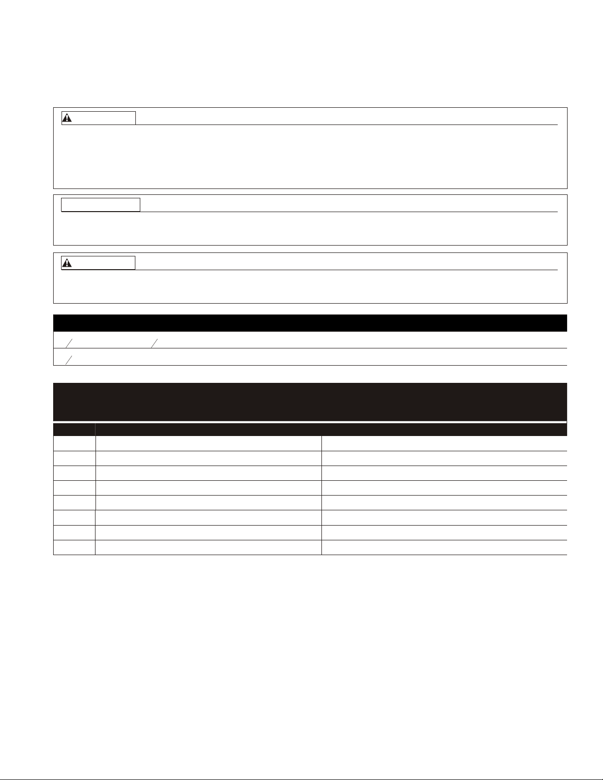
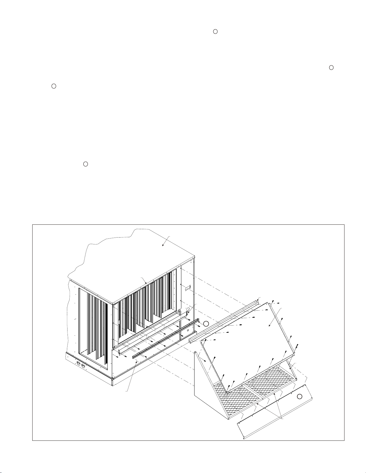
Step 1:
Remove lower barometric relief hood. Remove relief damper section from economizer or duct work.
Step 2:
Place relief damper section onto barometric relief damper adapter and secure with screws provided with power exhaust.
Step 3:
Place relief damper assembly into lower hood assembly where prepunched holes are in hood sides with screws from Step
1.
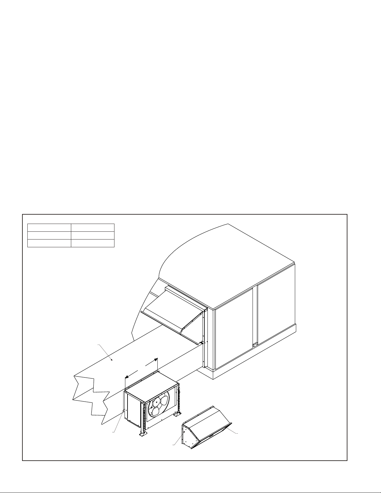
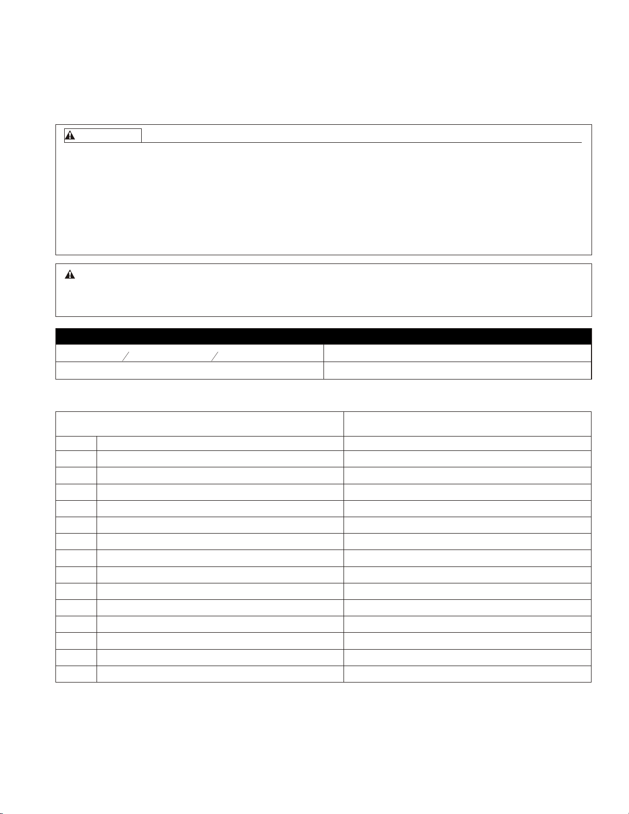
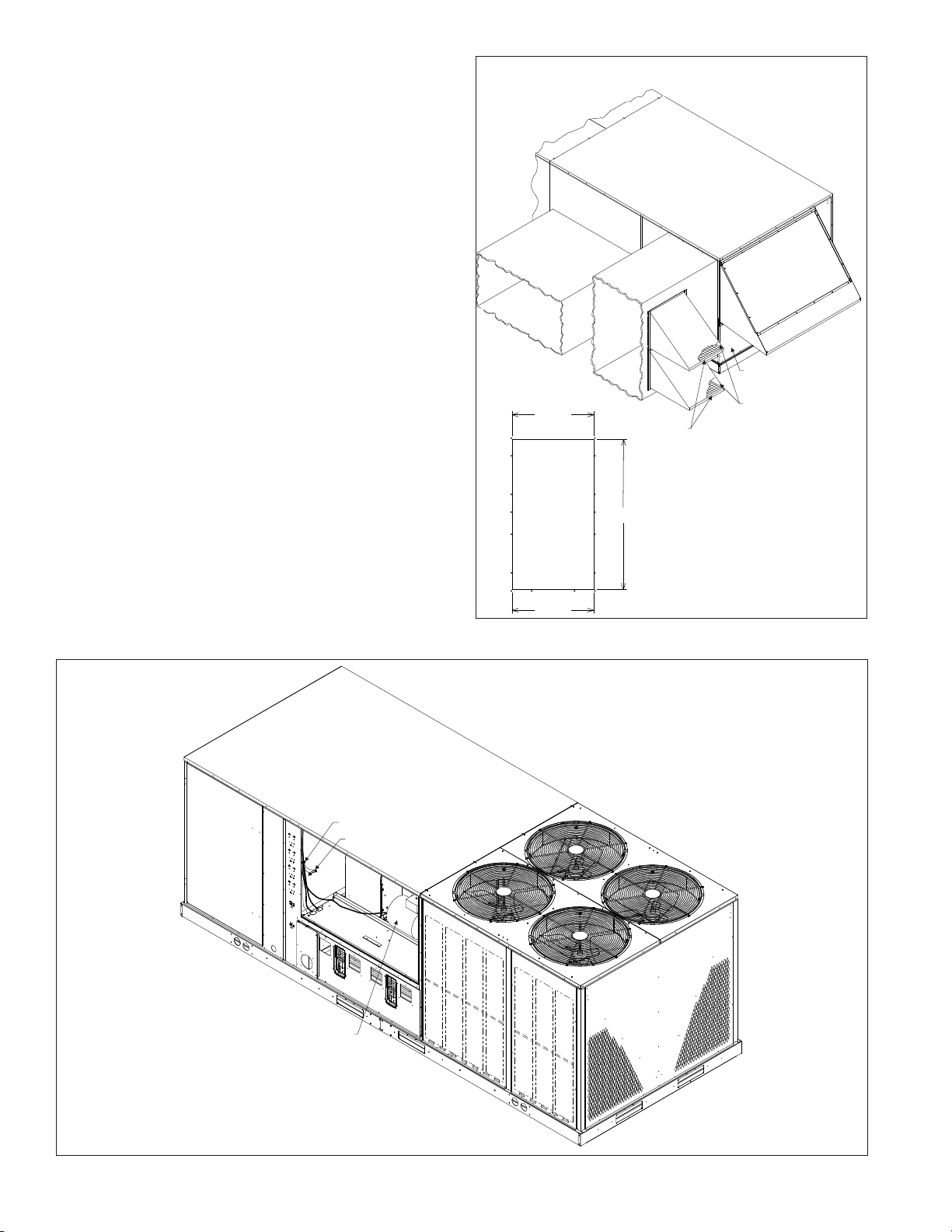
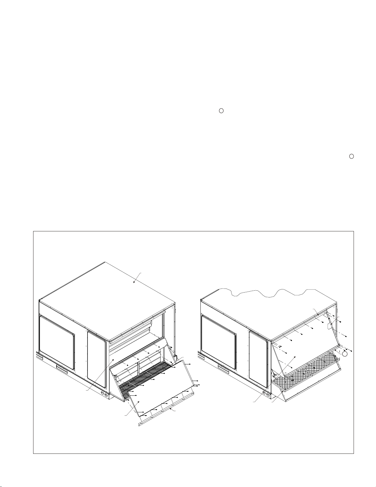
Horizontal Application:
Step 4:
Place power exhaust over hole in duct work and secure to duct work. Adjust support legs to level power exhaust. See
Figure 1.
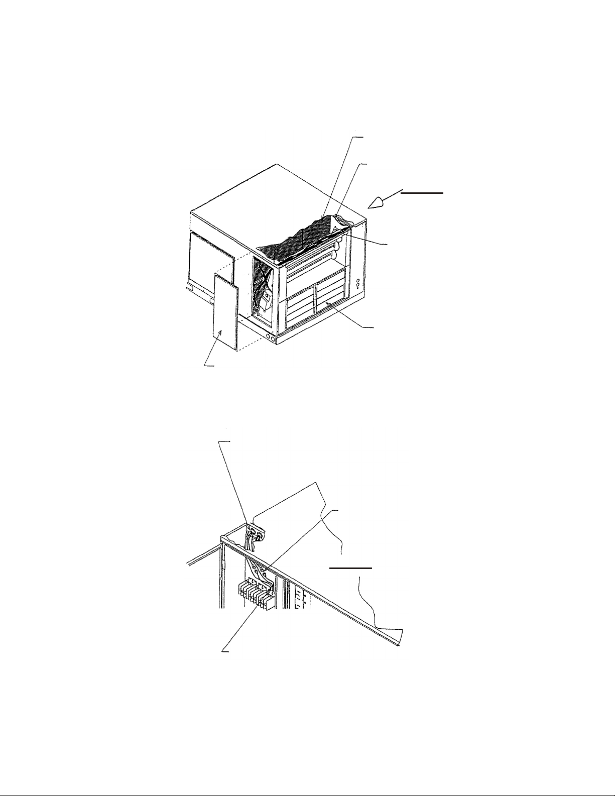
Vertical Application:
Step 5:
Place over hole where hood was located and secure. See Figure 2.
MODEL "A"
3 - 6 TON 23.750 REF
7 ½ TON 29.750 REF.
RETURN DUCT TO BE
PROPERLY SIZED FOR
AIRFLOW OF SPECIFIC
INSTALLATION
A
FIGURE1
2
SECURE TO DUCT WORK
PREPUNCHED HOLE FOR
RELIEF DAMPER
BAROMETRIC RELIEF DAMPER &
HOOD TO BE RELOCATED FROM
ECONOMIZER TO POWER
EXHAUST
Page 4
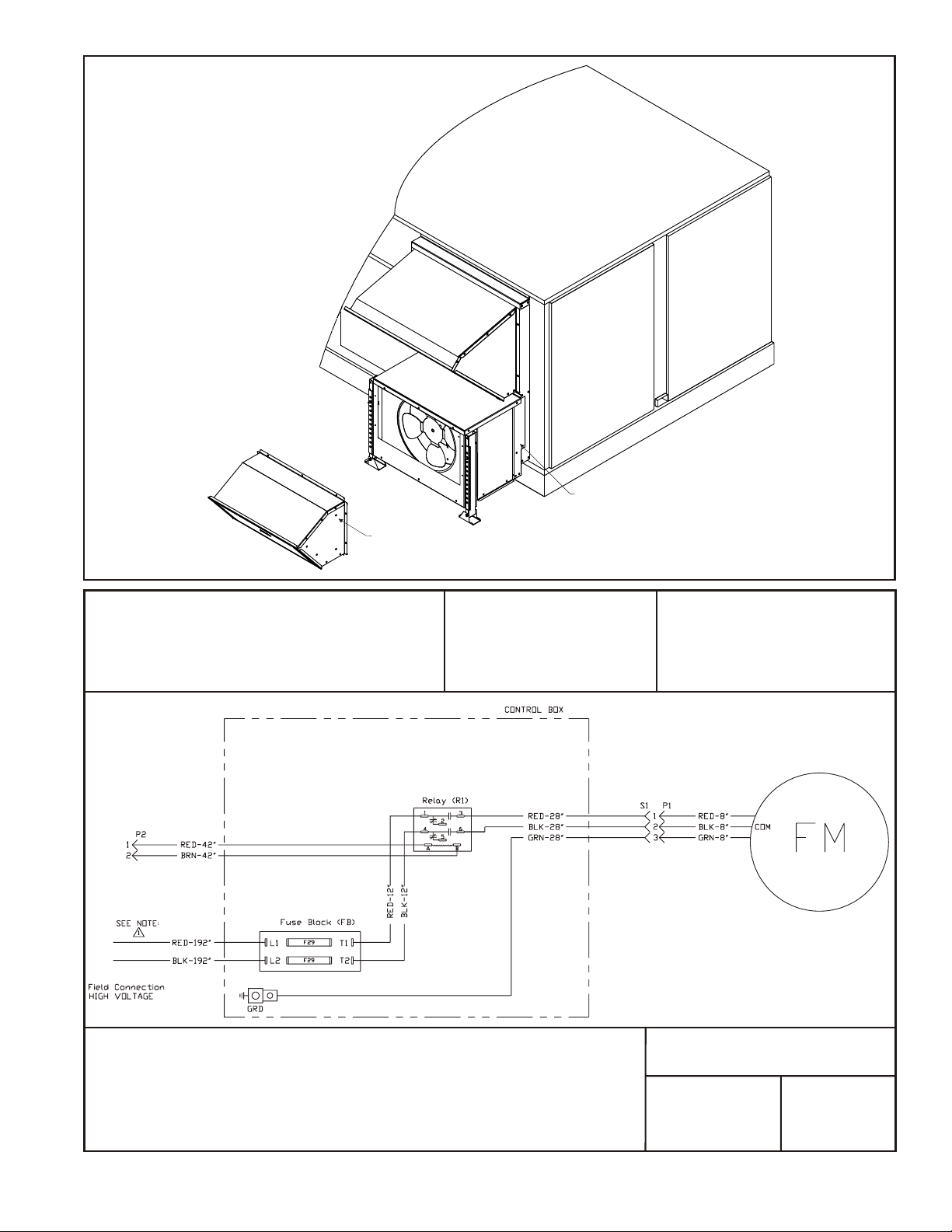
SECURE TO HOOD EXTENSION
PREPUNCHED HOLE FOR RELIEF DAMPER
NOTE:
COIL NOT SHOWN
FOR CLARITY
FIGURE 2
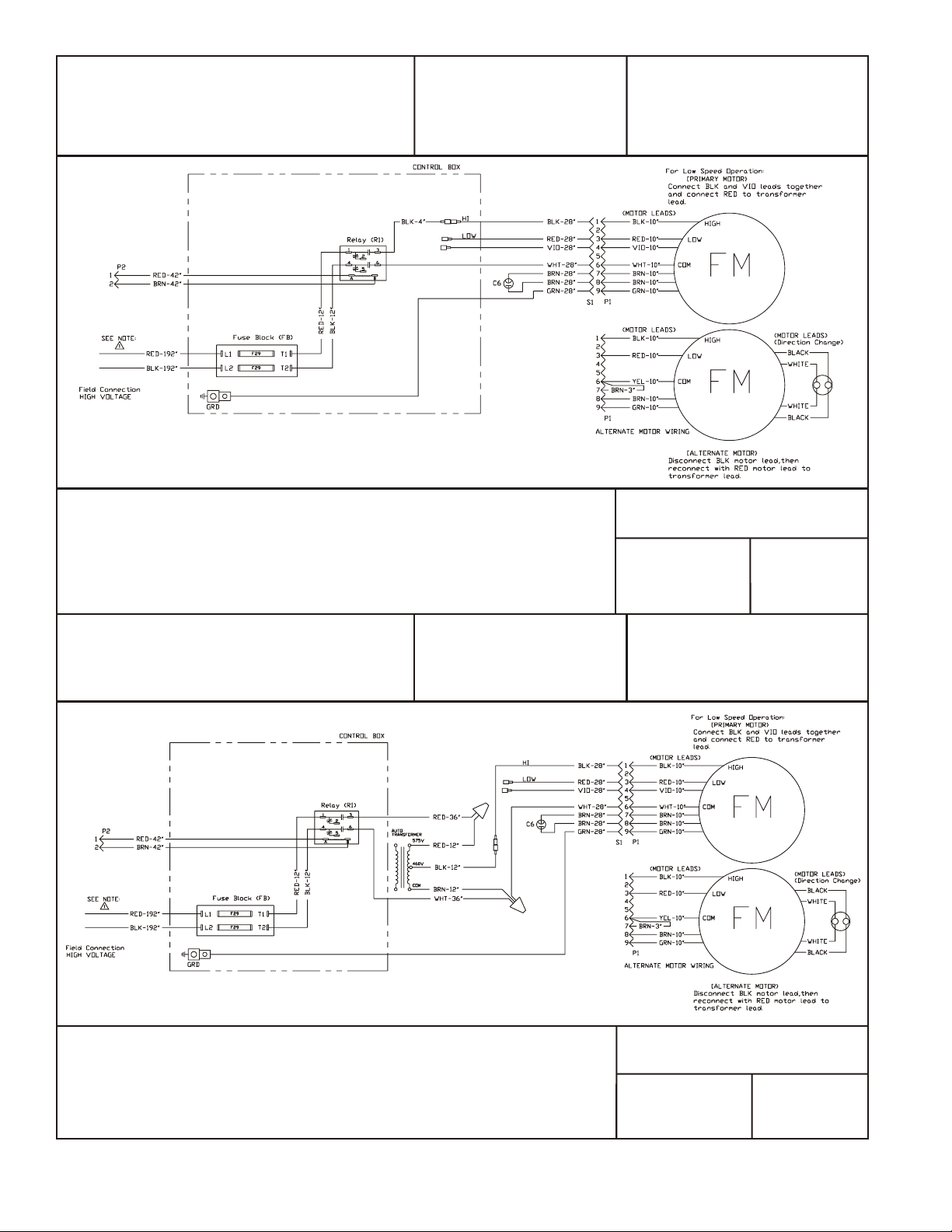
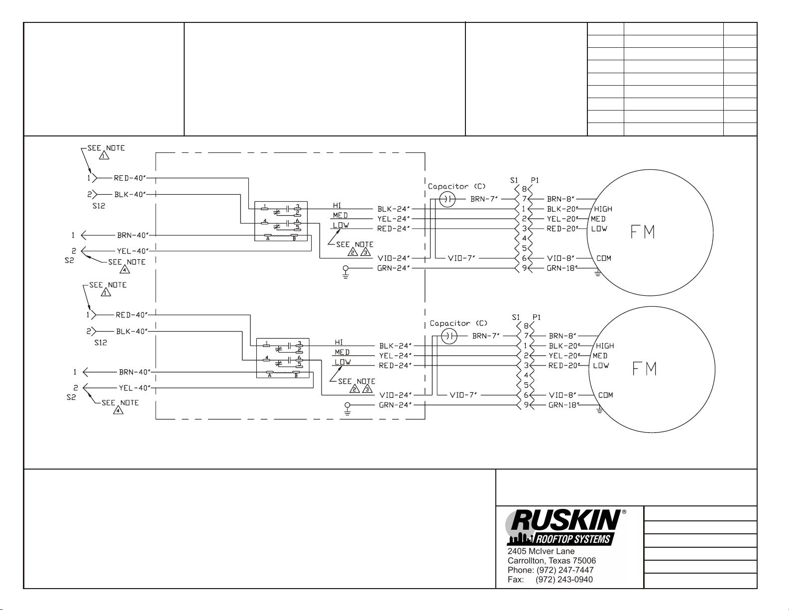
HARNESS DETAIL
COMPONENT CODE WIRE COLOR CODE
BLK Black BLU Blue
BRN Brown GRN Green
GRY Gray ORG Orange
RED Red VIO Violet
YEL Yellow
Notes:
230 Volt 1-Phase Power Ex haust for
RXRX-BGF03C / RXRX-BGF04C
RKKA/JKA/LKA/KMA/JMA/LMA/KNL/LNL/JNL 036-072
Roof top Sys tems, Inc.
2405 McIver Lane
Car roll ton, Texas 75006
Phone(972) 247- 7447
Fax (972) 243- 0940
RKNA/LNA/JNA 036-060
Date: June 17, 2009
Supersedes: 05-17-06
Drawn by: MGL
Unit #:60-465-20/08-21
Di a gram#: 4652021W
Ap proved by:
3
Page 5
HARNESS DETAIL
COMPONENT CODE
WIRE COLOR CODE
BLK Black BLU Blue
BRN Brown GRN Green
GRY Gray ORG Orange
RED Red VIO Violet
WHT White YEL Yellow
Notes:
HARNESS DETAIL
COMPONENT CODE
460 Volt 1-Phase Power Ex haust for
(-)XRX-BGF03D / (-)XRX-BGF04D/BGF06
RKKA/JKA/LKA/KMA/JMA/LMA/KNL/LNL/JNL 036-072
Roof top Sys tems, Inc.
2405 McIver Lane
Car roll ton, Texas 75006
Phone(972) 247- 7447
Fax (972) 243- 0940
BLK Black BLU Blue
BRN Brown GRN Green
GRY Gray ORG Orange
RED Red VIO Violet
WHT White YEL Yellow
RKNA/LNA/JNA 036-060
Date: June 17, 2009
Supersedes: 05-17-06
Drawn by: MGL
Unit #:60-465-20/08-31
Di a gram#: 4652031W
Ap proved by:
WIRE COLOR CODE
Notes:
SUPERSEDES 05-28-09
JUNE 17, 2009
575 Volt 1-Phase Power Ex haust for
(-)XRX-BGF03Y / (-)XRX-BGF04Y/BGF06
RKKA/JKA/LKA/KMA/JMA/LMA/KNL/LNL/JNL 036-072
Roof top Sys tems, Inc.
2405 McIver Lane
Car roll ton, Texas 75006
Phone(972) 247- 7447
Fax (972) 243- 0940
RKNA/LNA/JNA 036-060
Date: June 17, 2009
Supersedes: 05-17-06
Drawn by: MGL
Unit #:60-465-20/08-41
Di a gram#: 4652041W
Ap proved by:
RMIPE20
Page 6
INSTALLATION INSTRUCTIONS
MODELS (-)XRX-BGF05
ECONOMIZER POWER EXHAUST
WARN ING
This installation shall be carried out by a manufacturer's authorized representative, in accordance with the
requirements of the manufacturer. Failure to follow instructions can result in fire or explosion, causing property
damage, severe personal injury, or death. The qualified service personnel performing this work assumes
responsibility for this installation.
IM POR TANT
Damage to the product, resulting from failure to follow instructions or use of unauthorized parts, may be exclude from
the manufacturer's product warranty coverage.
WARN ING
Turn off electrical power and turn off main gas supply before beginning modification. Failure to do so can
cause electrical shock, explosion, or fire, resulting in property damage, personal injury, or death.
TOOLS RE QUIRED FOR IN STAL LA TION:
3
" electric drill with
8
1
" diameter drill bit for sheet metal.
8
5
" socket
16
(-)XRX-BGF05
PACK AGE CON TENTS
ITEM DE SCRIP TION PART No.
1 Power Exhaust Assembly 6046516 / PEA
2 Fan Blade 6046516 / 3465
3 Fan Motor 208-230 volt / 1 phase(C) 6046516 / 3677
4 Fan Motor 460 volt / 1 phase (D) 6046516 / 3694
5 Fan Motor 575 volt / 1 phase (Y) 6046516 / 3690
6 Relay (R1) 6046516 / 3400
7 Fuse Block 6046516 / 3370
8 Barometric Relief Adaptor 6046516 / ADP
Power Exhaust
C, D, Y Voltage
Page 7
INSTALLATION
1. Remove return cover. See Figure 1.
2. Connect new wire harness in control box back (View A) and route above economizer. See Figure 2.
FILTERS
EXISTING WIRE HARNESS
VIEW A
NEW WIRE HARNESS
ECONOMIZER
RETURN COVER
FIGURE 1
REMOVE PLUG IN BULKHEAD BEFORE
INSTALLING NEW WIRE HARNESS
INSTALL FUSES IN
FUSEHOLDERS
VIEW A
CONNECT WIRE HARNESS TERMINALS
TO ANY TWO OF THE THREE SUPPLY
FAN CONTACTOR TERMINALS.
FIGURE 2
2
Page 8
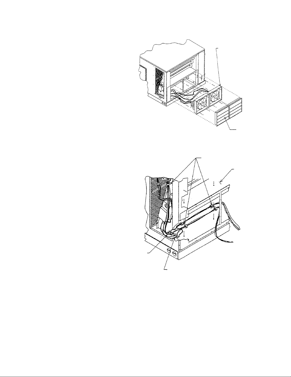
3. Remove relief dampers from economizer. See
Figure 3.
4. Connect power exhaust wiring:
Plug in control connections from power
exhausts to existing connections provided on
economizer.
Remove small rectangular cover beside control
connections on economizer and discard
(Figure 2).
Use screw that was removed in previous step to
attach ground terminals on wire harness.
Plug in power connections through the
rectangular holes revealed when the cover was
removed.
5. Route power and control connections under
divider panel using line clamps provided to take
up excess slack in wiring harness and avoid
contact between fan blades and wiring harness
during operation (Figure 4). secure each
power exhaust with (4) screws (2 in top flange
and 2 in bottom flange).
POWER EXHAUST
RELIEF DAMPERS
6. Connect ends of new wire harness to power
connections. See Figure 4.
7. Reinstall relief dampers.
8. Reinstall return cover.
9. All units are factory shipped for high speed. for
changing to low speed, see notes section on
wiring diagram.
POWER CONNECTIONS
FIGURE 3
(5) LINE CLAMPS
DIVIDER PANEL
CONTROL CONNECTIONS
FIGURE 4
SUPERSEDES 08-19-09
AUGUST 25, 2009
RMIPE16
Page 9
E# = WIRE END DESIGNATION
E2 STUD #6 18 Ga. Wire
E3 Female ¼ Quick Disc.
E4 Male ¼ Quick Disc. Insul
E6 Wire Nut Size 73B
HAR NESS LEADS
ARE 14 GA. WIRE
WITH NO END
DES IG NA TION
COMPONENT CODE
WIRE COLOR CODE
BLK Black
BLU Blue
BRN Brown
GRN Green
GRY Gray
ORG Orange
RED Red
VIO Violet
YEL Yellow
Re vi sion Change Date
ECN 3032 Changed wir ing diagram 08-18-09
CON NEC TOR & CON TACT CON FIG U RA TION
P1 (303903) PLUG - (303912) PIN
S1 (303904) CAP - (303913) SOCKET
Notes:
1. Con nect J12 to S12 at economizer. High volt age har ness.
2. A. Power Ex haust wired for High speed.
B. For Med speed dis con nect BLK at re lay (3).
C. For Low speed dis con nect BLK at re lay (3).
3. Be sure all leads from mo tor have been cov ered with tape.
4. Con nect J2 to S2 at economizer. Low volt age har ness.
208-230/460/575 Volt 1 Phase Power Ex haust for
RKNL / RLNL 180-300
Date: August 18, 2009
Supercedes: 06-29-09
Drawn by: MGL
Unit #: 60-465-16-21/31/41
Di a gram#: 604651641w
Ap proved by:
Page 10
INSTALLATION INSTRUCTIONS
MODELS (-)XRD-RGCM3
HORIZONTAL AIRFLOW ECONOMIZERS
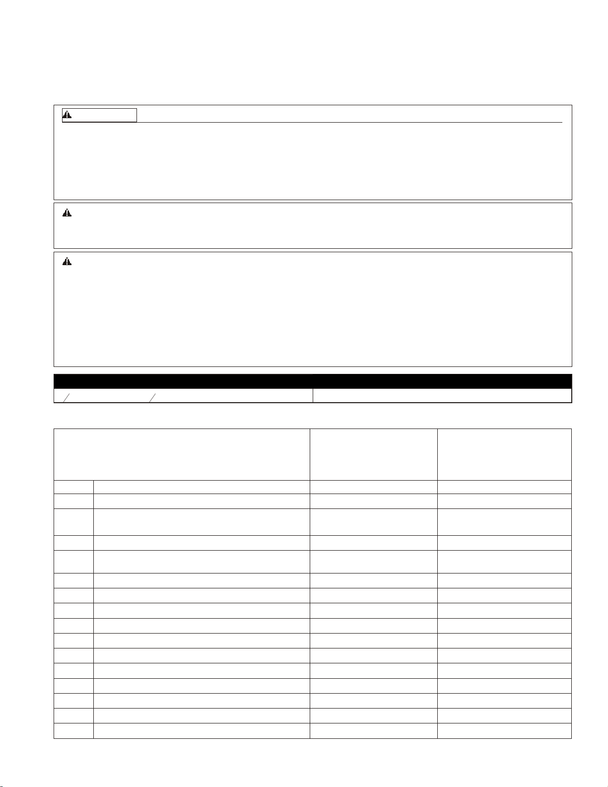
WARN ING
THIS ACCESSORY IS TO BE INSTALLED BY A QUALIFIED, LICENSED SERVICE PERSON. TO AVOID
UNSATISFACTORY OPERATION OR DAMAGE TO THE PRODUCT AND POSSIBLE UNSAFE CONDITIONS,
INCLUDING ELECTRICAL SHOCK, REFRIGERANT LEAKAGE AND FIRE, THE INSTALLATION
INSTRUCTIONS PROVIDED WITH THIS ACCESSORY MUST BE STRICTLY FOLLOWED AND THE PARTS
SUPPLIED USED WITHOUT SUBSTITUTION. DAMAGE TO THE PRODUCT RESULTING FROM NOT
FOLLOWING THE INSTRUCTIONS OR USING UNAUTHORIZED PARTS MAY BE EXCLUDED FROM THE
MANUFACTURER’S WARRANTY COVERAGE.
WARN ING
DISCONNECT ELECTRICAL POWER TO THE UNI T. FAILURE TO DO S O CAN CAUSE ELE CTRICAL SHOCK
RESULTING IN PERSONAL INJURY OR DEATH.
TOOLS RE QUIRED FOR IN STAL LA TION:
3
" elec tric drill with
8
Wa ter proof ex te rior duct seal ant Sheet metal tools (e.g. shears)
5
" socket Small flat blade (0.125" wide) screw driver
16
TABLE 1
PACK AGE CON TENTS
ITEM DE SCRIP TION PART No.
1
2
3
4
5
6
7
8
9
10
11
12
13
14
Discharge Air Sensor (Hardware Bag)
(2) Permanent Filters
(2) Spotweld Assy - Bird Screen
(2) Exhaust Air Rainhood - Top
OA Rainhood Assy - Left Side
OA Rainhood Assy - Right Side
(2) Exhaust Air Rainhood - Left Side
(2) Exhaust Air Rainhood – Right Side
OA Rainhood Assy - Filter Bracket Strip
OA Rainhood Assy – Top
OA Rainhood - Front Filter Support
OA Filter Rail
Hardware Bag
Exhaust Air Rain Hood Spacer
(-)XRD-RGCM3 economizer with controller,
actuator, and outside enthalpy sensor attached
6039416 / 3112
6039416 / 8568 (23.875" X 23.875")
6039416 / BSWA
6039416 / EHT2
6039416 / EHSL
6039416 / EHSR
6039416 / EHS3L
6039416 / EHS3R
6039416 / ADP
6039416 / EHT
6039416 / EHB
6039416 / FCH
6039416 / HDW
6039416 / ADP2
Page 11
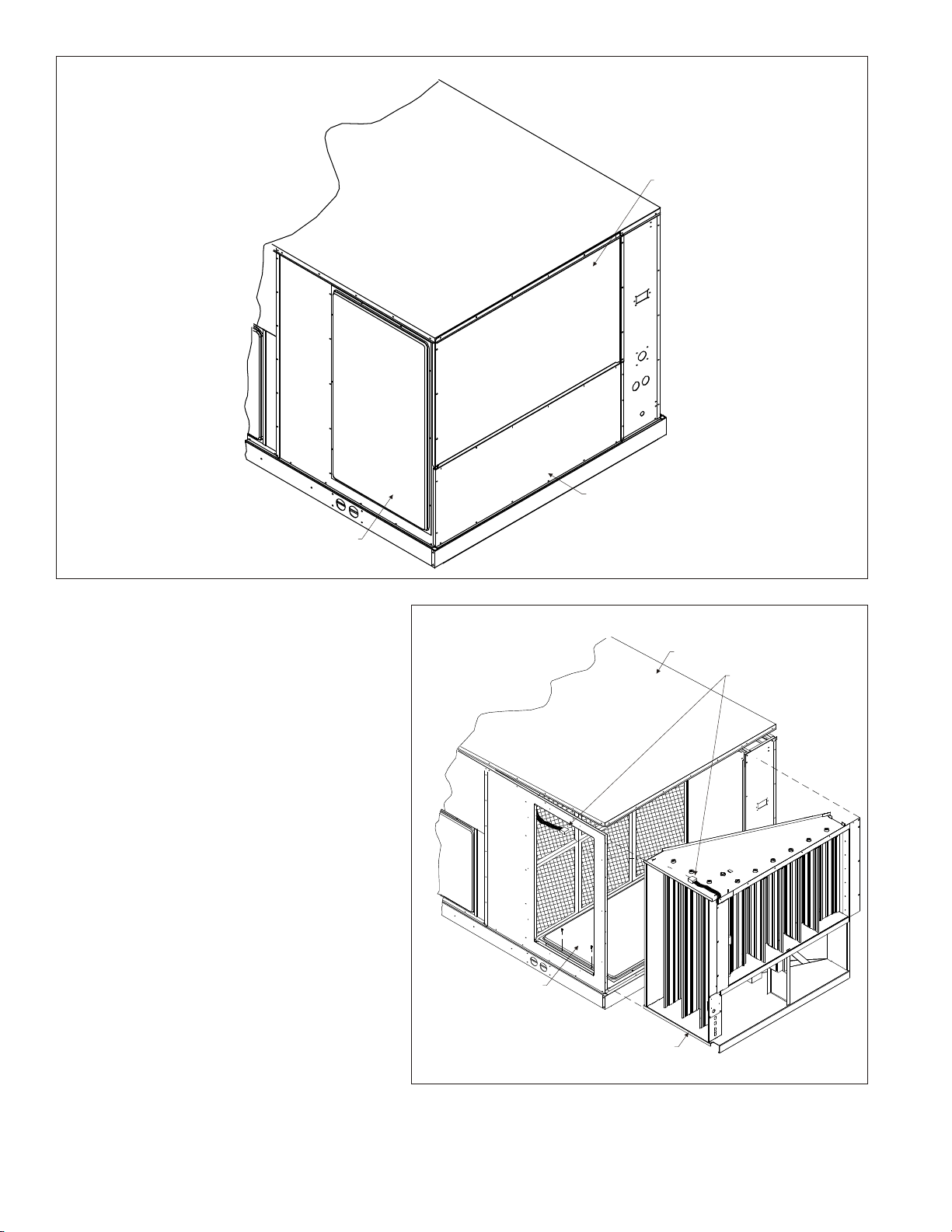
FIGURE 1
PANEL - TOP LEFT
PANEL - LEFT BOTTOM SECTION
RETURN COVER
STEP 1:
Immediately upon receipt, all cartons and contents
should be inspected for transit damage. Units with
damaged cartons should be opened immediately.
If damage is found, it should be noted on the
delivery papers and a damage claim filed with the
last carrier.
STEP 2:
Remove RETURN COVER, PANEL – TOP LEFT,
and PANEL – LEFT BOTTOM SECTION from the
unit and retain for reuse (SEE FIGURE 1). Retain
screws.
STEP 3:
Fasten RETURN COVER (SEE FIGURE 2) over
bottom return opening using 4 retained screws.
STEP 4:
Remove screws from 3 sides of ROOF PANEL so
that it can be raised during economizer insertion.
STEP 5:
Remove jumper plug PL7 and connect unit
ECONOMIZER PLUG to economizer mating plug
and slide economizer into unit. Reinstall jumper
plug PL7to PL21 located on economizer.
FIGURE 2
RE TURN COVER
ECONOMIZER
(SEE BILL OF MA TE RIAL)
A1005-01
ROOF PANEL
ECONOMIZER PLUG
A1005-01
2
Page 12
STEP 6:
Mount PANEL – LEFT BOTTOM SECTION to unit (SEE
FIGURE 3). Use only 2 screws (one on each side) for easy
removal during calibration.
STEP 11:
Fasten 11 OA RA INHOOD - FRONT FILTER SUPPORT to
PANEL – TOP LEFT. The bottom lip should support the
PERMANENT FILTERS.
STEP 7:
Fasten FILTER BRACKET STRIP to unit using 2 screws
(one on each side). See Table 1 for identification.
STEP 8:
Fasten 12 OA FILTER RAIL to FILTER BRACKET STRIP
with 4 screws. Fasten FILTER BRACKET STRIP to
economizer with 4 neoprene washer head screws
provided.
STEP 9:
Fasten OA RAINHOOD - LEFT SIDE and OA
RAINHOOD - RIGHT SIDE to unit using 3 screws
provided.
STEP 10:
Slide PERMANENT FILTERS between OA
RAINHOOD - LEFT SIDE and OA RAINHOOD - RI GHT
SIDE back into the 12 OA FILTER RAIL.
STEP 12:
Fasten PANEL – TOP LEFT to OA RAINHOOD - LEFT
SIDE and OA RAINHOOD - RIGHT SIDE and 11 OA
RAINHOOD - FRONT FILTER SUPPORT using 16
screws.
STEP 13:
Position the OA RAINHOOD ASSY – TOP under edge
of ROOF PANEL.
STEP 14:
Re-secure ROOF PANEL using existing screws.
FIGURE 3
PANEL - LEFT BOTTOM SECTION
ROOF PANEL (REF.)
12
PANEL - TOP LEFT
11
A1012-01
3
Page 13
STEP 15:
Provide opening in return air duct to mount the two
barometric relief dampers and hoods (SEE FIGURE 4).
Locate a convenient distance from unit.
STEP 16:
Using self-drilling screws provided, assemble exhaust air
rain hoods ( EXHAUST AIR RAINHOOD – TOP,
EXHAUST AIR RAINHOOD - LEFT SIDE, EXHAUST
AIR RAINHOOD - RIGHT SIDE, SPOTWELD ASSY BIRD SCREEN) and install in return air duct. Use sealant
(not provided) as required.
STEP 17:
Remove the blower motor access panel (SEE FIGURE 5).
STEP 18:
Connect the DISCHARGE AIR SENSOR to wires 51
and 52 located in the blower motor compartment.
NOTE:
Mixed air sensor should be secured with the included wire
tie to avoid entanglement with the blower and direct
contact with any sheet metal surfaces.
STEP 19:
Replace the blower motor access panel.
FIGURE 4
SUPPLY AIR
25.250
RETURN AIR
DUCT
PANEL - LEFT
BOTTOM SECTION
STEP 20:
Upon start-up check the economizer sequence of
operation using the steps provided in these instructions.
After testing unit operation and setting outside air damper
minimum position, secure PANEL – LEFT BOTTOM
SECTION (SEE FIGURE 3) with remaining screws.
FIGURE 5
WIRE TIE
25.250
47.250
A1005-01
INDOOR MOTOR
A1006-01
4
Page 14
DI RECT MOUNT ECONOMIZER SE QUENCE OF OP ER A TION
GEN ERAL
This accessory economizer package is designed to save
energy costs by using outdoor air for cooling and
ventilation in place of mechanical cooling whenever
possible. The economizer continuously monitors indoor
and outdoor air conditions and compares them to a
user-selected setpoint to determine if free cooling is
available.
AC CES SO RIES
RXRX-AV02 — Dual Enthalpy Up grade Kit
For maximum energy savings, this upgrade kit will allow
the economizer to compare the outdoor air enthalpy to the
return air enthalpy, instead of a user-selected setpoint to
determine if "free cooling" is available.
RXRX-AR02 - Wall-Mounted Car bon Di ox ide Sen sor
For installations requiring Demand Control Ventilation
(DCV) based upon indoor air levels of carbon dioxide
(CO2). When the unit supply fan is running, the CO2 sensor
modulates the outside air damper to maintain a
user-selected CO2 level inside the occupied space.
Energy savings are achieved by not bringing in excessive
amounts of outdoor air when the indoor air conditions are
suitable. Energy savings can be substantial on buildings
with highly variable occupancy rates.
Wall-Mounted Remote Potentiometer
For installations requiring remote adjustment of damper
minimum position by the occupants, a remote
potentiometer, such as the Honeywell S963B1128 can be
used.
RXRX-BFF02C, RXRX-BFF02D, RXRX-BFF02Y —
Power Exhaust Kit
For installations requiring more space static pressure relief
than can be obtained with the standard barometric relief
damper included with the economizer, a power exhaust kit
can be added.
B. Range of adjustment is from 0-100% (2-10V); in
most applications the minimum position is
adjusted to allow 10% to 25% outside air to enter
the system.
C. The Outside Air Damper Minimum Position
potentiometer can be adjusted at any time.
D. Whenever the "G" (supply fan) signal is present,
the damper will open to this minimum position
unless:
a. It may modulate to a greater position if
overridden by the CO2 sensor (DCV).
b. It may not open if overridden by the discharge
air temperature sensor (Freeze Protect
Mode).
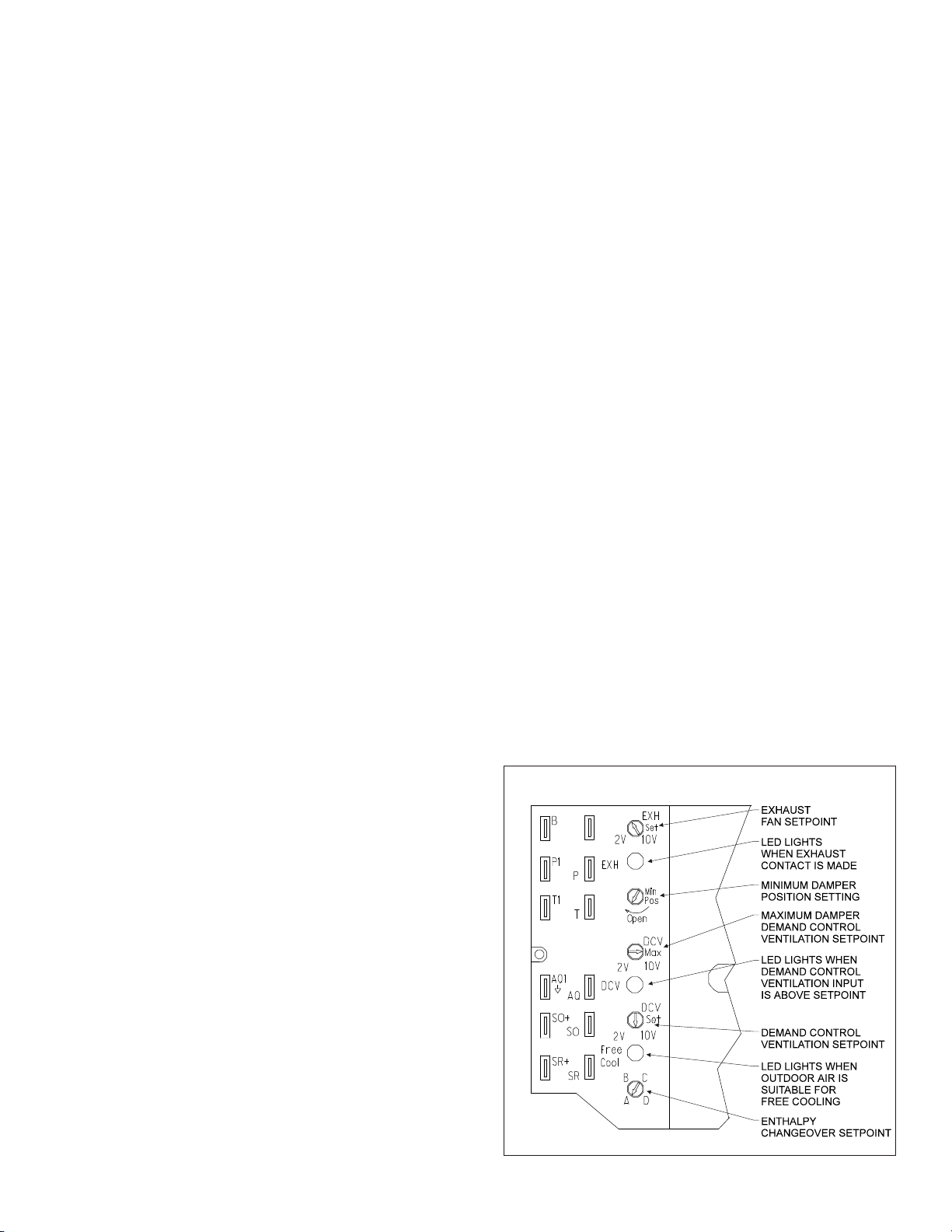
3. DCV Max — Demand Control Ventilation (DCV)
Maximum Setpoint
A. The DCV maximum position potentiometer allows
the installer to limit the amount of outdoor air flow
into the building when the DCV overrides the
mixed air sensor.
B. Setting the DCV maximum position of the damper
prevents the introduction of large amounts of hot
or cold air into the space.
C. Note: If the DCV maximum position is set below
the outside air damper minimum position, the
minimum position overrides the DCV maximum
position (negating the function of the DCV).
4. DCV Set — Demand Control Ventilation (DCV)
Setpoint
A. The DCV can be any sensor that provides a
2-10Vdc output. The DCV modulates the outdoor
damper to provide ventilation based on
occupancy. Typically, a carbon dioxide (CO2)
sensor is used to indirectly monitor occupancy
level.
B. No cooling signal (e.g.Y1, Y2) is required for the
DCV to override the outdoor air damper when
ventilation requires outdoor air.
C. The controller must receive a "G" (supply fan)
signal to open the damper.
D. Range of adjustment is from 2 Volts to 10 Volts.
E. The DCV setpoint can be adjusted at any time.
FIGURE 6
STARTUP
Attach connector from Economizer Controller to Rooftop
Control Panel Connector and install discharge/mixed air
temperature sensor per installation guide.
AD JUST MENTS
5 po ten ti om eters with screw driver ad just ment slots,
start ing from top of con trol ler
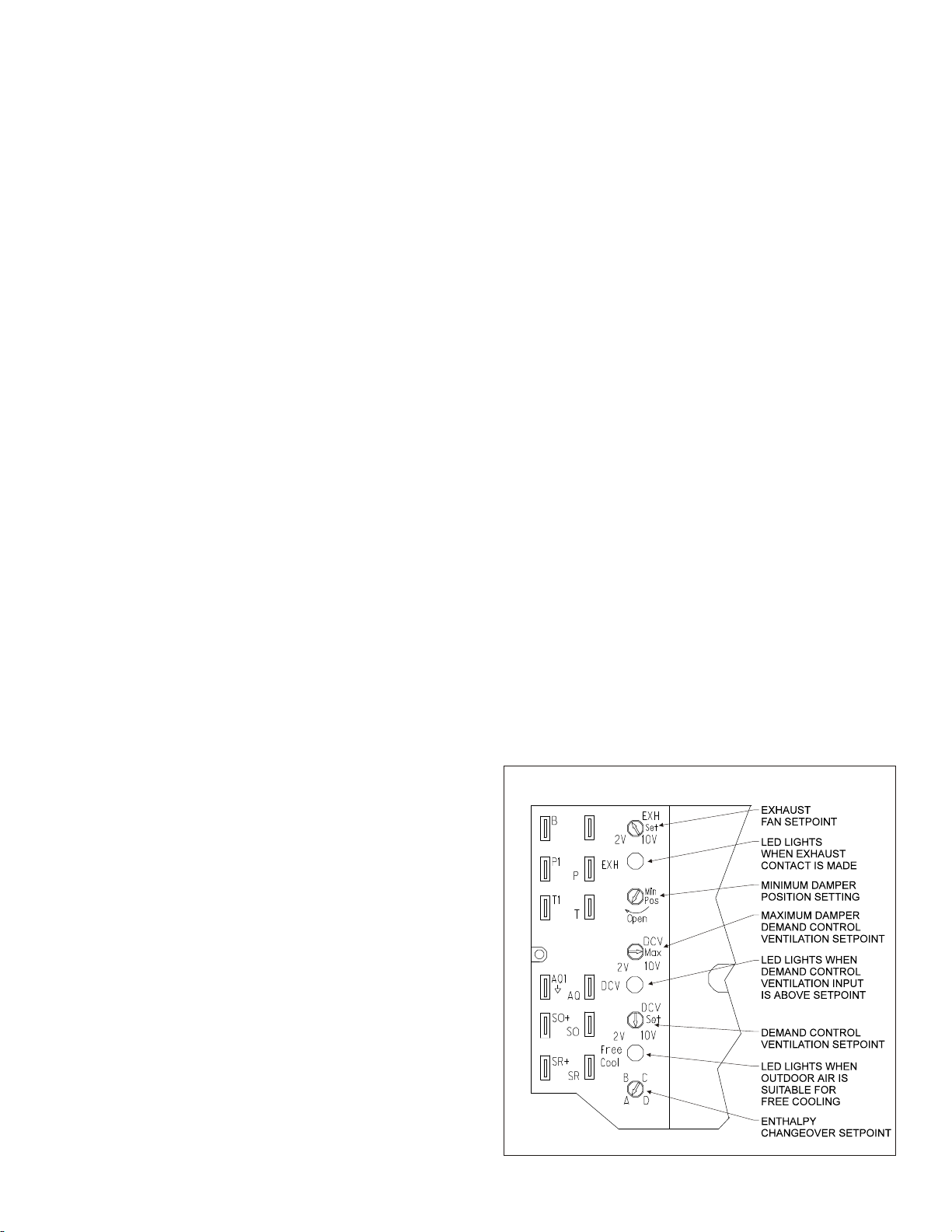
1. EXH Set — Adjustments for (optional) power ex haust
A. The outside air damper position at which the
power exhaust fan(s) will engage. The LED
labeled EXH below the potentiometer adjustment
will indicate when power exhaust is available.
When the power exhaust call is made, the
controller provides a 60 ±30 second delay before
exhaust fan activation to allow the damper to
reach the appropriate position.
B. Range of adjustment is from 0-100% (2-10V); in
most applications the power exhaust is set to
engage at about 70% outside air.
5
Page 15
F. The controller compares the CO2 sensor input to
the setpoint setting to determine the damper
minimum position.
a. If the actual CO2 level is below the setpoint,
then the damper minimum position is
determined by the damper minimum position
potentiometer setting.
b. If the actual CO2 level rises above the
setpoint, then the damper minimum position is
overridden proportionally more open.
c. If the discharge air temperature drops below
48°F (Freeze Protect Mode), the DCV input
will be overridden and the damper may not
open.
G. Compatible CO2 sensors will have a 2-10Vdc
output for a 0-1500 ppm CO2 input.
H. Ensure proper polarity of the sensor wires when
connecting to the economizer controller. Incorrect
polarity negates the sensor signal.
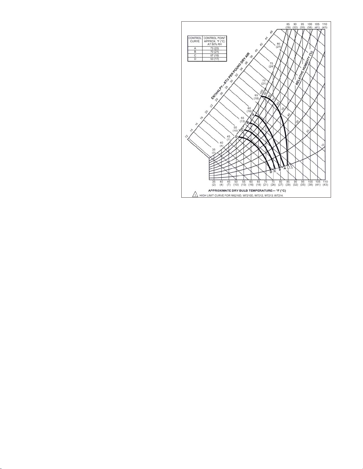
5. Economizer Setpoint
A. Only the coolest, driest outside air is used for
economizer operation when the potentiometer is
on setting "D". For greatest energy savings, the
potentiometer is on setting "A".
B. Adjustment range is A, B, C, or D
a. Setting "A" = 73F db or 27 Btu/lbm @ 50% RH
b. Setting "B" = 70F db or 25 Btu/lbm @ 50% RH
c. Setting "C" = 67F db or 23 Btu/lbm @ 50% RH
d. Setting "D" = 63F db or 22 Btu/lbm @ 50% RH
C. Economizer Setpoint potentiometer can be
adjusted at any time.
D. The controller compares the enthalpy sensor input
with the economizer setpoint to determine if free
cooling is available.
a. Single enthalpy strategy: If outdoor air
enthalpy is lower than the setpoint, then free
cooling is available. Note: The
factory-installed 620-ohm resistor must be in
place across terminals SR and SR+.
b. Dual enthalpy strategy: If outdoor air enthalpy
is lower than return air enthalpy, then free
cooling is available.
1. Note: If using dual enthalpy, the Economizer
Setpoint must be at the "D" setting.
2. The factory-installed 620-ohm jumper must
be removed to install the dual enthalpy
upgrade kit.
NOR MAL OP ER A TION
1. Fan Only (G)
A. Damper will go to minimum position (in 90
seconds or less) whenever the "G" (supply fan)
signal is present.
B. When "G" signal is removed, the outside air
damper closes against blade seals for tight shutoff
of outside air.
C. If the discharge air temperature drops below 48ºF,
then the control will override the minimum position
setting and will modulate the outside air damper
closed.
2. Call for First Stage of Cooling (Y1)
A. Economizer Unavailable (warm outdoor air).
Compressor 1 is commanded on without delay.
B. Economizer Available (free cooling). The
controller tries to maintain a discharge air
temperature of 53ºF ± 5 by modulating the outside
air damper position.
FIGURE 7
3. Call for Second Stage of Cooling (Y2)
A. Economizer Unavailable (warm outdoor air).
Compressor 2 is commanded on without delay.
B. Economizer Available (free cooling). Compressor
1 is commanded on without delay. The controller
tries to maintain a discharge air temperature of
53ºF ± 5 by modulating the outside air damper
position. Compressor 2 is not activated in the
economizer mode.
4. Call for Heat
A. Standard Air Conditioner with electric or gas heat.
(W1 & W2)
a. The Thermostat controls the stages of heating
directly.
b. If the control detects that the supply fan is on
(through its "G" input), then the control will
open the damper to minimum position.
c. If the discharge air temperature drops below
48ºF, then the control will override the
minimum position setting and will modulate
the outdoor damper closed.
B. Heat Pump Operation (B)
a. The "B" signal from the Thermostat allows
operation of the compressors to provide
heating without delay.
b If the control detects that the supply fan is on
(through its "G" input), then the control can
open the damper to minimum position.
c. If the discharge air temperature drops below
48ºF, then the control will override the
minimum position setting and will modulate
the outdoor damper closed.
5. Low Ambient Compressor Lockout – None present.
6
Page 16

TROU BLE SHOOT ING
1. Checkout requires a handheld multimeter, 9V battery,
a 5.6k ohm .25 watt resistor, a 1.2k ohm .25 watt
resistor, a jumper wire with .25" quick connect
terminals, and the 620 ohm resistor that is
factory-installed across terminals SR+ and SR. The
terminal names below reference the economizer
controller. Use the following flowcharts for to diagnose
unit.
2.
a. Disconnect power to the unit.
b. Jumper P to P1 (factory installed jumper is
normally present).
c. Remove outdoor air enthalpy sensor from
terminals SO+ and SO and install the 1.2k ohm
resistor.
d. Put 620 ohm resistor across terminals SR+ and
SR (factory installed 620 ohm resistor is normally
present and can be used).
e. Put 5.6k ohm resistor across T and T1.
3.
a. Turn (EXH Set) Exhaust fan Setpoint
potentiometer fully CCW.
b. Turn (Min Pos) Minimum Outside Air Damper
potentiometer fully CCW.
c. Turn (DCV Max) Demand Control Ventilation
Maximum potentiometer fully CW.
d. Turn (DCV Set) Demand Control Ventilation
Setpoint potentiometer fully CCW.
e. Turn enthalpy potentiometer to "D".
7
Page 17
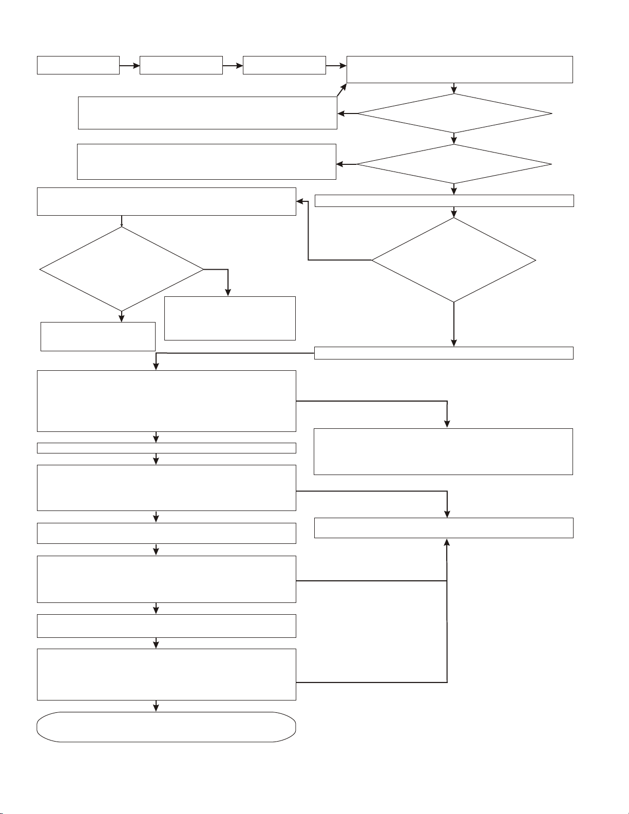
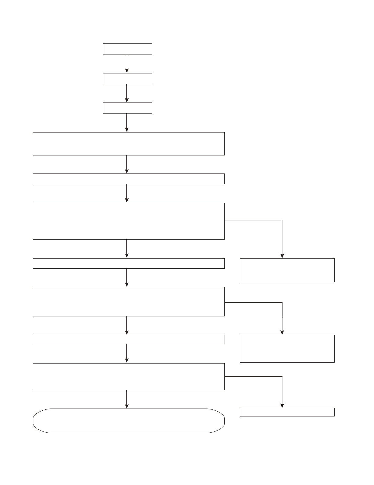
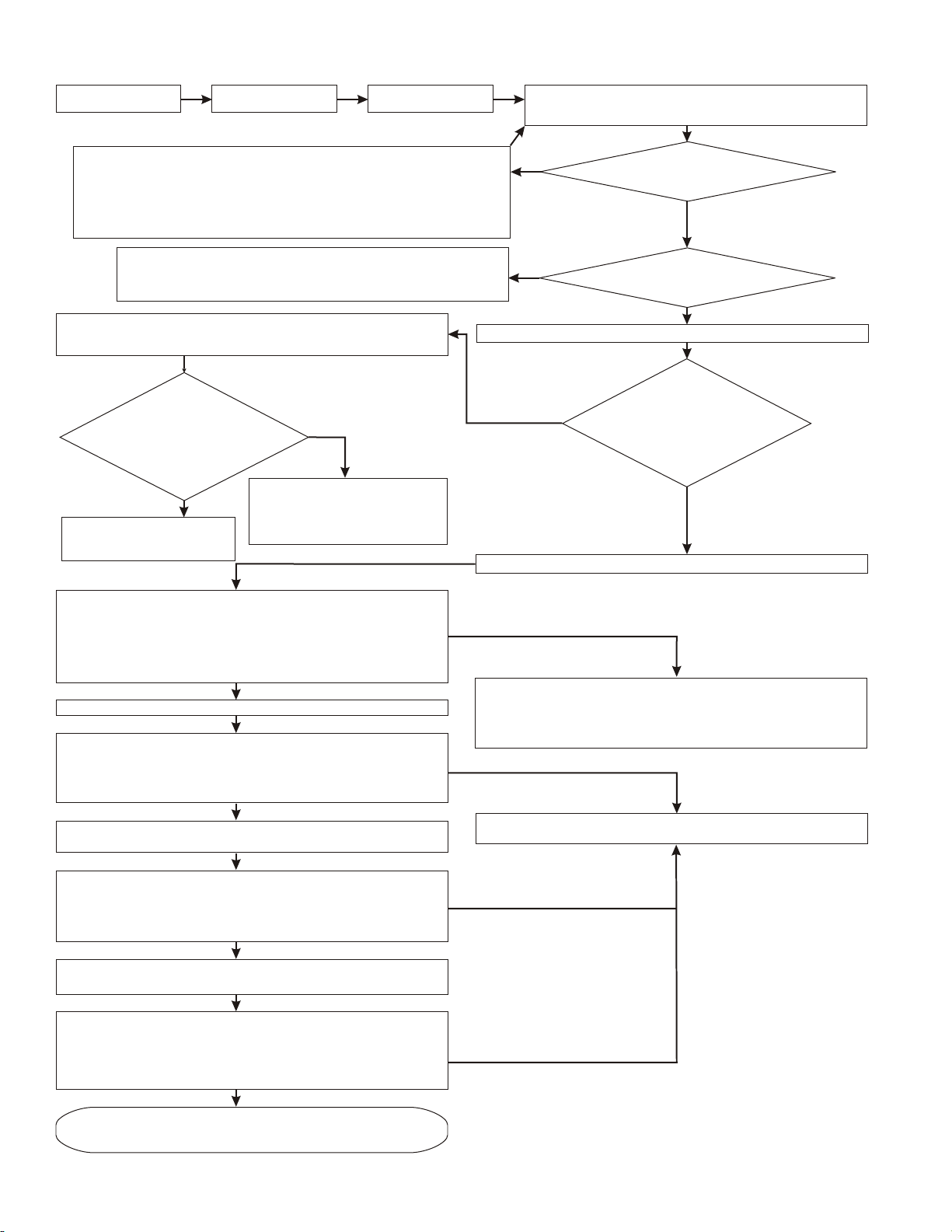
BASIC ECONOMIZER OPERATION
START Perform STEP 2 Perform STEP 3
Put thermostat fan setting to "CONTINUOUS FAN"
Reapply Power to the Unit
Set thermostat so neither heating or cooling is called
Connect Economizer Wire Harness to Unit
Check Thermostat Connections
Check for 24 VAC at Unit Transformer
Check Unit Wire Harness
Check Economizer Controller Model Number
Perform STEP 2 & STEP 3 again.
If problem continues, replace controller
Unplug Economizer Wire Harness from Unit Wire harness and Install
Jumper Plug (Jumpers Y1 Thermostat to Y1 Compressor and Jumpers
Y2 Thermostat to Y2 Compressor)
If one
stage of cooling
is called by the
thermostat, do first stage
compressor(s) run? If both stages
are called, do both stages
of compressors
run?
NO
Check Thermostat Wiring
Check Unit Wiring Harness
The "Free Cooling" LED turns on & the EXH LED turns on.
If only one stage of cooling is called by the thermostat, then that stage
will turn off. If two stages are called by the thermostat, then only the
second stage will turn off. The power exhaust (optional) contacts will
close after 60 +/- 30 seconds. The outside air damper opens
approximately 50% (this position is determined by the actual resistance
of the 5.6k ohm resistor placed across terminals T and T1).
Set enthalpy potentiometer to D (fully CW).
The "Free Cooling" LED turns off & the EXH LED turns off.
If only one stage of cooling is called by the thermostat, then that stage
will turn back on. If two stages are called by the thermostat, then both
stages will turn on. The power exhaust (optional) contacts open & the
outside air damper fully closes.
Set enthalpy potentiometer back to A (fully CCW).
Remove 5.6k ohm resistor and jumper terminals T to T1.
(W7213A1016)
YES
Check Economizer Wiring
Harness. Check Unit wiring
harness at economizer
connection for proper terminal
location
YES
YES
NO
NO
Turn down thermostat setting so that a call for cooling is present.
NO
Set enthalpy potentiometer on economizer controller to A (fully CCW).
NO
Recheck STEP 2 and STEP 3. If LED’s turn on and damper motor
does not operate, measure voltage between terminals 24V COM and
(+ (white wire)). If approximately 6 VDC is present, replace damper
actuator. If voltage not present, or LED’s do not light replace controller.
NO
Recheck STEP 2 and STEP 3.
If problem continues replace controller
24 VAC power
available between terminal TR and
TR1?
YES
Are all LED's off &
outside air damper fully closed?
YES
If one
stage of cooling
is called by the
thermostat, do first stage
compressor(s) run? If both stages
are called, do both stages
of compressors
run?
YES
The "Free Cooling" LED turns on & the EXH LED turns on. If only one
stage of cooling is called by the thermostat, then that stage will turn off.
If two stages of cooling are called by the thermostat, then only the
second stage will turn off. The power exhaust (optional) contacts will
close after 60 +/- 30 seconds. The outside air damper fully opens
YES
Remove jumper from terminals T to T1 and leave open (simulates the
The "Free Cooling" LED remains on & the EXH LED turns off.
If only one stage of cooling is called by the thermostat, then that stage
will remain off. If two stages of cooling are called by the thermostat,
then only the second stage will remain off. The power exhaust
(optional) contacts opens & the outside air damper fully closes
Economizer Controller, Actuator, Wiring are correct.
Remove resistors, reconnect wires, and set up
Freeze Protect mode).
YES
potentiometers per jobsite requirements.
8
NO
NO
Page 18
HEAT PUMP OPERATION
(Perform BASIC ECONOMIZER OPERATI ON check first)
START
Perform STEP 2
Perform STEP 3
Put thermostat fan setting to "CONTINUOUS FAN"
Reapply Power to the Unit
Turn down thermostat setting so that a call for cooling is present.
Set enthalpy potentiometer on economizer controller to A (fully CCW).
The "Free Cooling" LED turns on & the EXH LED turns on.
If only one stage of cooling is called by the thermostat, then that stage will turn off.
If two stages are called by the thermostat, then only the second stage will turn off.
The power exhaust (optional) contacts will close after 60 +/- 30 seconds.
The outside air damper opens approximately 50% (this position is determined by
the actual resistance of the 5.6k ohm resistor placed across terminals T and T1).
YES
Reset the thermostat setting so that a call for heating is present.
The "Free Cooling" LED turns off & the EXH LED turns off.
If only one stage of heating is called by the thermostat, then that stage will turn on.
If two stages are called by the thermostat, then both stages will turn on.
The power exhaust (optional) contacts will open The outside air damper fully
closes.
NO
Perform Basic Economizer Operation
check first. Recheck STEP 2 and
STEP 3
NO
YES
Turn Min Pos potentiometer fully CW.
The outside air damper drives fully open.
The EXH LED turns on.
The power exhaust (optional) contacts will close after
approximately 60 +/- 30 seconds.
YES
Heat Pump Operation is Correct.
Remove resistors, reconnect wires, and set up
potentiometers per jobsite requirements.
Check for 24 VAC at B terminal.
Check for B signal at thermostat.
Check Unit wire harness.
Check Economizer Wire harness.
NO
Replace controller.
9
Page 19
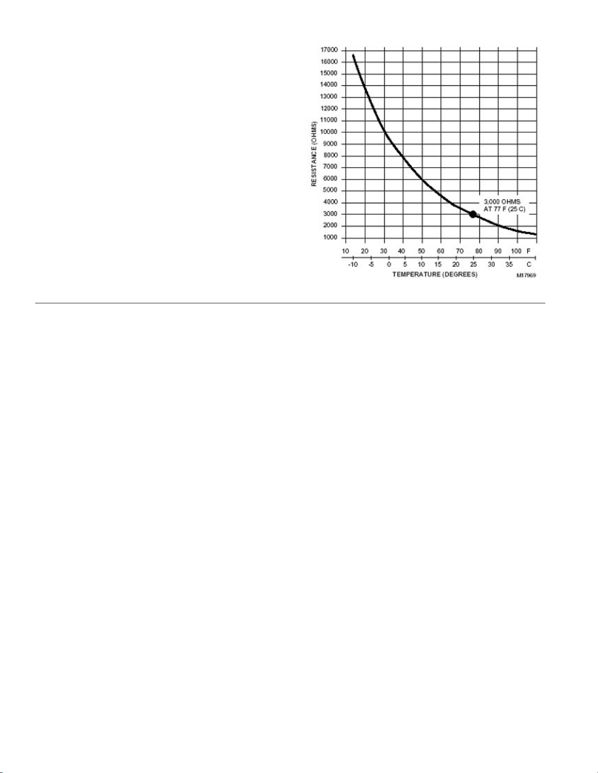
Use the following graph and the multimeter to verify proper
operation of the mixed air / discharge air temperature
sensor.
Measure the resistance (ohms) of the mixed air / discharge
air temperature sensor with the multimeter. Look up the
equivalent temperature on the graph. This should be the
same as temperature the mixed air / discharge air sensor is
detecting. If it is not, replace the mixed air /discharge air
sensor.
NOTES
1. The mist eliminator (Permanent Outdoor Air Filter), is
of aluminum mesh construction and should be
cleaned by flushing regularly with warm soapy water.
The replacement mist eliminator size is listed on the
first page of these instructions.
2. When diagnosing the system, the best results are
obtained by first putting the fan setting on the
Thermostat to the "Continuous Fan" mode.
3. Operation of the optional power exhaust only depends
upon the supply fan running and the damper position
(it is possible to set the minimum position high enough
to engage the power exhaust in the heating mode).
4. This economizer requires a two-stage thermostat.
5. Upon loss of power to the unit or economizer, the
outside air damper will spring close shut in about 5
seconds.
6. Compressor Time Delays, Compressor Interstage
Delays, Compressor Low Ambient Lockouts, etc. are
not provided by the economizer controller.
10
Page 20
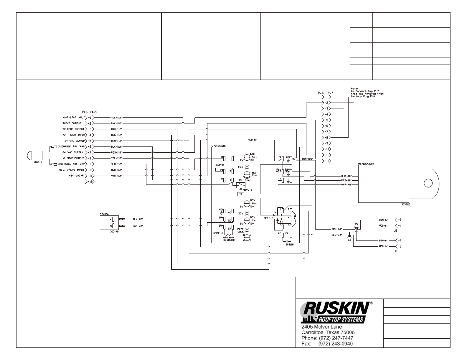
HARNESS ENDS AT PL6 & PL7
COMPONENT CODE
C7400A Fresh Air Sensor
9RT1H Mixed Air Sensor
J2 Power Exhaust Cap
MS7106K Damper Actuator 24v
PL6 Male A/C Unit Plug
PL7 Female A/C Unit Plug
PL20 Female Economizer Cap
PL21 Male Smoke Plug
W7213A Logic Module
WIRE COLOR CODE
BLK Black BLU Blue
BRN Brown GRN Green
GRY Gray ORG Orange
PNK Pink RED Red
TAN Tan VIO Violet
WHT White YEL Yellow
Re vi sion Change Date
ECN 2259 Change brown wire length 07/09/09
CONNECTOR & CONTACT CONFIGURATION
PL7 (303917) CAP - (303902) SOCKET
J2 (303909) CAP - (303902) SOCKET
Notes:
1. Unit wir ing shown as ref er ence only. Check unit wir ing for ac tual unit wir ing.
2. Re lays 1K and 2K ac tu ate when the Out door Air Enthalpy is lower than the Re turn Air Enthalpy.
3. 1S is an elec tronic switch which closes when pow ered by a 24 VAC in put.
4. Fac tory in stalled re sis tor should be re moved only if C7400 Dif fer en tial Enthalpy Sen sor is added.
5. Y2 must be en er gized for the com pres sor to op er ate.
Hor i zon tal Mod u lat ing Gear Economizer
RKNL / RLNL 180-300
Date: July 9, 2009
Supercedes: 03-19-09
Drawn by: MGL
Unit #: 60-394-16
Di a gram#: 6039416W
Ap proved by:
Page 21

SUPERSEDES 06-04-09
JULY 15, 2009
RMIHE16
Page 22
INSTALLATION INSTRUCTIONS
MODELS (-)XRD-PDCM3 & (-)XRD-SDCM3
VERTICAL AIRFLOW ECONOMIZERS
WARN ING
THIS ACCESSORY IS TO BE INSTA LLED BY A QUA LIFIED, LICENSED SERVICE PERSON. TO A VOID UNSATISFA CTORY
OPERATION OR DA MAGE TO THE PRODUCT A ND POSSIBLE UNSAFE CONDITIONS, INC LUDING ELECTRICAL SHOCK,
REFRIGERANT LEAKAGE AND FIRE, THE INSTALLATION INSTRUCTIONS PROVIDED WITH THIS ACCESSORY MUST
BE STRICTLY FOLLOWED AND THE PARTS SUPPLIED USED WITHOUT SUBSTITUTION. DAMAGE TO THE PRODUCT
RESULTING FROM NOT FOLLOWING THE INSTRUCTIONS OR USING UNAUTHORIZED PARTS MAY BE EXCLUDED
FROM THE MANUFACTURER’S WARRANTY COVERAGE.
WARN ING
DISCONNECT ELECTRICAL POWER TO TH E UNIT. FA ILURE TO DO SO CA N CA USE ELECTRIC A L SHOCK RESULTING
IN PERSONAL INJURY OR DEATH.
WARN ING
THE SMOKE DETECTOR MUST NOT BE RELIED UPON AS THE PRIMARY SMOKE DETECTION IN BUILDING SAFETY.
THE ECONOMIZER SMOKE DETECTOR DE-ENERGIZES THE SUPPLY FAN AND CLOSES THE OUTSIDE AIR DAMPER
WHEN SMOKE IS DETECTED. REFER TO ENCLOSED SMOKE DETECTOR INSTRUCTIONS (SECTION 7) FOR TESTING
OF ADEQUATE SMOKE SENSOR AIRFLOW UPON INSTALLATION OF (-)XRD-SDCM3 ECONOMIZER WITH SMOKE
DETECTOR CAPA BILITIES. SUFFICIENT DUCTED AIR VELOC ITY MUST BE PRESENT ACROSS THE SMOKE DETEC TOR
SAMPLING TUBE TO ENSURE PROPER OPERATION. ADDING POWERED EXHAUST MAY BE REQUIRED IN BUILDINGS
WITH EXCESSIVE ENVELOPE AIR LOSSES AND/OR RESTRICTIVE RETURN AIR CONDITIONS TO THE UNIT
PREVENTING ADEQUATE RETURN AIR TO THE UNIT WHEN ECONOMIZER IS OPEN TO OUTSIDE AIR.
TOOLS RE QUIRED FOR IN STAL LA TION:
3
" electric drill with
8
5
" socket Small flat blade (0.125" wide) screwdriver
16
TABLE 1
(-)XRD-SDCM3
economizer with smoke
detector, con trol ler,
ac tu a tor, and out side
enthalpy sen sor at tached
PACK AGE CON TENTS
(-)XRD-PDCM3
economizer with con trol ler,
ac tu a tor, and out side
enthalpy sen sor at tached
ITEM DE SCRIP TION PART No. PART No.
1
2
3
4
5
6
7
8
9
10
11
12
13
14
15
Dis charge Air Sen sor (Hardware Bag)
(2) Per ma nent Fil ters
Spotweld Assy - Bird Screen
Ex haust Air Rainhood Assy – Birdscreen
Front Sup port
OA Rainhood Assy - Left Side
OA Rainhood Assy - Right Side
Ex haust Air Rainhood - Left Side
Ex haust Air Rainhood – Right Side
OA Fil ter Rail Assy
OA Rainhood Assy – Top
OA Rainhood - Front Fil ter Sup port
Hardware Bag
Smoke Detector w/ Harness
Sampling Tube
Sampling Tube Bracket
6036413B / 3112 6036413S / 3112
6036413B / 8567
(11.875" X 23.875")
6036413S / 8567
(11.875" X 23.875")
6036413B / BSWA 6036413S / BSWA
6036413B / EHB2 6036413S / EHB2
6036413B / EHSL 6036413S / EHSL
6036413B / EHSR 6036413S / EHSR
6036413B / EHS2L 6036413S / EHS2L
6036413B / EHS2R 6036413S / EHS2R
6036413B / EHT2 6036413S / EHT2
6036413B / EHT 6036413S / EHT
6036413B / EHB 6036413S / EHB
6036413B / HDW 6036413S / HDW
------ 6036413S / 3528
------ 6036413S / 3532
------ 6036413S / BRKT
Page 23
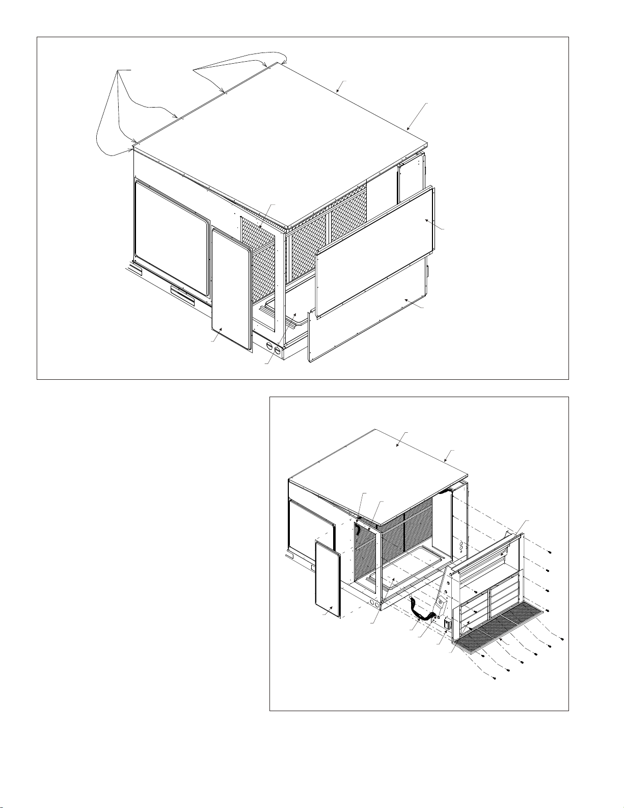
FIGURE 1
(-)XRD-PDCM3 Shown - (-)XRD-SDCM3 Similar
LEAVE THESE
SCREWS ENGAGED
RETURN COVER
FRONT SIDE
ROOF PANEL REMOVE
SCREWS FROM THREE
SIDES (FRONT, LEFT AND
BACK) EXCEPT AS NOTED
FILTERS
LEFT PANEL - UPPER
(REMOVE TO BE REUSED
IN RAIN HOOD ASSEMBLY
LEFT PANEL - LOWER
(REMOVE TO BE REUSED
IN RAIN HOOD ASSEMBLY
DOWNFLOW RETURN OPENING
STEP 1:
Immediately upon receipt, all cartons and contents
should be inspected for transit damage. Units with
damaged cartons should be opened immediately.
If damage is found, it should be noted on the
delivery papers and a damage claim filed with the
last carrier. Compare carton(s) contents to
PACKAGE CONTENTS List (TABLE 1) above to
note any missing items.
STEP 2:
Remove RETURN COVER, LEFT PANEL –
UPPER and LOWER PANELS – LEFT BOTTOM
SECTION from the unit and retain for reuse (SEE
FIGURE 1). Retain screws.
STEP 3:
Remove screws from 3 sides of ROOF PANEL so
that it can be raised during economizer insertion.
NOTE 1:
Remove shipping bracket, PERMANENT
FILTERS, OA RAINHOOD - LEFT SIDE, OA
RAINHOOD - RIGHT SIDE, EXHAUST AIR
RAINHOOD - LEFT SIDE and EXHAUST AIR
RAINHOOD – RIGHT SIDE from fresh air opening.
(SEE FIGURE 2).
STEP 4:
Remove jumper plug and slide economizer into unit
return air section (SEE FIGURE 2). After the
economizer is installed, connect unit
ECONOMIZER PLUG to economizer mating plug.
PDCM3 - Reinstall jumper plug PL7 to PL21
(located on economizer). SDCM3 - Save jumper
plug PL7 in this compartment for diagnostic
purposes.
FIGURE 2
RE TURN COVER
DOWNFLOW RE TURN OPEN ING
ROOF PANEL
PLUG
FIL TERS
WIRE HARNESS
ACTUATOR
CONTROLLER
ECONOMIZER ASSEMBLY
A1010-01
FRONT SIDE
NOTE 1
A1011-01
2
Page 24
STEP 5:
Secure economizer and SPOTWELD ASSY - BIRD
SCREEN along bottom with six screws as shown (SEE
FIGURE 2). See TABLE 1 for identification.
STEP 6:
Fasten EXHAUST AIR RAINHOOD - LEFT SIDE and
EXHAUST AIR RAINHOOD – RIGHT SIDE to barometric
relief opening (lower opening) on the economizer (SEE
FIGURE 3). Fasten with six screws. See FIGURE 4 for
identification of EXHAUST AIR RAINHOODS.
STEP 7:
Fasten EXHAUST AIR RAINHOOD ASSY –
BIRDSCREEN FRONT SUPPORT under edge of LEFT
PANEL – LOWER using six screws. Do not install a screw
in the rightmost hole in the panels at this time.
STEP 8:
Fasten LEFT PANEL – LOWER and EXHAUST AIR
RAINHOOD ASSY – BIRDSCREEN FRON T SUPPORT
to the top of the EXHAUST AIR RAINHOOD - LEFT
SIDE and EXHAUST AIR RAINHOOD – RIG HT SIDE
which was previously installed on the unit (SEE STEP 7).
STEP 9:
Attach OA FILTER RAIL ASSY to economiz er center
support, EXHAUST AIR RAINHOOD - LEFT SIDE and
EXHAUST AIR RAINHOOD – RIGHT SIDE and L EFT
PANEL – LOWER using screws provided.
STEP 10:
Position the OA RAINHOOD ASSY – TOP under edge
of ROOF PANEL. Do not install screws at this time.
STEP 11:
Fasten OA RAINHOOD - LEFT SIDE and OA
RAINHOOD - RIGHT SIDE to unit using screws provided
(2 each on (-)XRD-PDCM3, and on (-)XRD-SDCM3).
STEP 12:
Slide PERMANENT FILTERS between OA
RAINHOOD - LEFT SIDE and OA RAINHOOD - RI GHT
SIDE back into the OA FILTER RAIL ASSY.
STEP 13:
Fasten 11 OA RA INHOOD - FRONT FILTER SUPPORT to
LEFT PANEL – UPPER with six screw s. The bottom lip
should support the PERMANENT FILTERS. Do not
install a screw in the rightmost hole in the panels at this
time.
STEP 14:
Fasten LEFT PANEL – UPPER to OA RAINHOOD LEFT SIDE and OA RAINHOOD - RIGHT SIDE and 11
OA RAINHOOD - FRONT FILTER SUPPORT using
screws (12 on (-)XRD-PDCM3, and on (-)XRD-SDCM3).
STEP 15:
Re-secure ROOF PANEL using the washer head screws
that were removed in STEP 3 from the ROOF PANEL.
FIGURE 3
(-)XRD-PDCM3 Shown - (-)XRD-SDCM3 Similar
(See Table 1 for identification of parts)
ECON. CENTER
SUPPORT (REF.)
LEFT PANEL - LOWER
ROOF PANEL (REF.)
LEFT PANEL - UPPER
11
A1012-01
3
Page 25
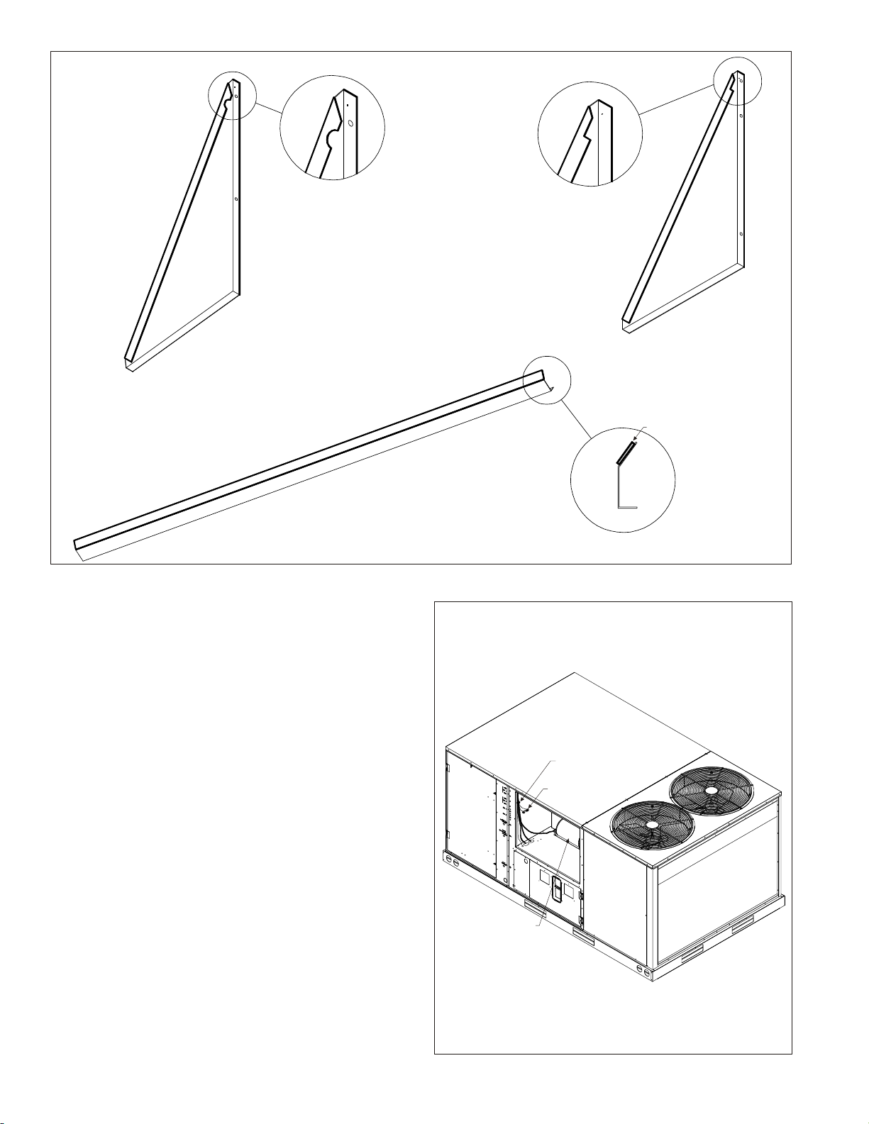
FIGURE 4
EXHAUST AIR RAIN HOOD
(LOWER LEFT SIDE)
OUTSIDE AIR RAIN HOOD
(UPPER LEFT SIDE)
SEAL STRIP
EXHAUST AIR RAIN HOOD ASSEMBLY
(BIRDSCREEN FRONT SUPPORT)
STEP 16:
Remove the BLOWER MOTOR ACCESS PANEL (SEE
FIGURE 5).
STEP 17:
Connect the j DISCHARGE AIR SENSOR to wires 51
and 52 located in the blower motor compartment.
NOTE:
Mixed air sensor should be secured with the included wire
tie to avoid entanglement with the blower and direct
contact with any sheet metal surfaces.
STEP 18:
Replace the BLOWER MOTOR ACCESS PANEL.
STEP 19:
Upon start-up check the economizer sequence of
operation using the steps provided in these instructions.
After testing unit operation and setting outside air damper
minimum position, replace RETURN COVER with
remaining screws.
END VIEW
A1005-01
FIGURE 5
WIRE TIE
INDOOR MOTOR
A1006-01
4
Page 26
DI RECT MOUNT ECONOMIZER SE QUENCE OF OP ER A TION
GEN ERAL
This accessory economizer package is designed to save
energy costs by using outdoor air for cooling and
ventilation in place of mechanical cooling whenever
possible. The economizer continuously monitors indoor
and outdoor air conditions and compares them to a
user-selected setpoint to determine if free cooling is
available.
AC CES SO RIES
(-)XRX-AV02 — Dual Enthalpy Up grade Kit
For maximum energy savings, this upgrade kit will allow
the economizer to compare the outdoor air enthalpy to the
return air enthalpy, instead of a user-selected setpoint to
determine if "free cooling" is available.
(-)XRX-AR02 - Wall-Mounted Car bon Di ox ide Sen sor
For installations requiring Demand Control Ventilation
(DCV) based upon indoor air levels of carbon dioxide
(CO2). When the unit supply fan is running, the CO2 sensor
modulates the outside air damper to maintain a
user-selected CO2 level inside the occupied space.
Energy savings are achieved by not bringing in excessive
amounts of outdoor air when the indoor air conditions are
suitable. Energy savings can be substantial on buildings
with highly variable occupancy rates.
Wall-Mounted Remote Potentiometer
For installations requiring remote adjustment of damper
minimum position by the occupants, a remote
potentiometer, such as the Honeywell S963B1128 can be
used.
(-)XRX-BFF02C, (-)XRX-BFF02D, (-)XRX-BFF02Y —
Power Exhaust Kit
For installations requiring more space static pressure relief
than can be obtained with the standard barometric relief
damper included with the economizer, a power exhaust kit
can be added.
B. Range of adjustment is from 0-100% (2-10V); in
most applications the power exhaust is set to
engage at about 70% outside air.
2. Min Pos — Outside Air Damper minimum position
A. Adjust the minimum position potentiometer to
allow the minimum amount of outdoor air, as
required by local codes, to enter the building.
B. Range of adjustment is from 0-100% (2-10V); in
most applications the minimum position is
adjusted to allow 10% to 25% outside air to enter
the system.
C. The Outside Air Damper Minimum Position
potentiometer can be adjusted at any time.
D. Whenever the "G" (supply fan) signal is present,
the damper will open to this minimum position
unless:
a. It may modulate to a greater position if
overridden by the CO2 sensor (DCV).
b. It may not open if overridden by the discharge
air temperature sensor (Freeze Protect
Mode).
3. DCV Max — Demand Control Ventilation (DCV)
Maximum Setpoint
A. The DCV maximum position potentiometer allows
the installer to limit the amount of outdoor air flow
into the building when the DCV overrides the
mixed air sensor.
B. Setting the DCV maximum position of the damper
prevents the introduction of large amounts of hot
or cold air into the space.
C. Note: If the DCV maximum position is set below
the outside air damper minimum position, the
minimum position overrides the DCV maximum
position (negating the function of the DCV).
STARTUP
Operational Note
For (-) XRD-SDCM3 economizer. After these startup
adjustments have been completed, perform airflow
measurement tests on the smoke detector to ensure
adequate smoke detector sensing air. Refer to enclosed
smoke detector instructions (section 7).
Attach connector from Economizer Controller to Rooftop
Control Panel Connector and install discharge/mixed air
temperature sensor per installation guide.
AD JUST MENTS
5 po ten ti om eters with screw driver ad just ment slots,
start ing from top of con trol ler
1. EXH Set — Adjustments for (optional) power ex haust
A. The outside air damper position at which the
power exhaust fan(s) will engage. The LED
labeled EXH below the potentiometer adjustment
will indicate when power exhaust is available.
When the power exhaust call is made, the
controller provides a 60 ±30 second delay before
exhaust fan activation to allow the damper to
reach the appropriate position.
FIGURE 6
5
Page 27

4. DCV Set — Demand Control Ventilation (DCV)
Setpoint
A. The DCV can be any sensor that provides a
2-10Vdc output. The DCV modulates the outdoor
damper to provide ventilation based on
occupancy. Typically, a carbon dioxide (CO2)
sensor is used to indirectly monitor occupancy
level.
B. No cooling signal (e.g.Y1, Y2) is required for the
DCV to override the outdoor air damper when
ventilation requires outdoor air.
C. The controller must receive a "G" (supply fan)
signal to open the damper.
D. Range of adjustment is from 2 Volts to 10 Volts.
E. The DCV setpoint can be adjusted at any time.
F. The controller compares the CO2 sensor input to
the setpoint setting to determine the damper
minimum position.
a. If the actual CO2 level is below the setpoint,
then the damper minimum position is
determined by the damper minimum position
potentiometer setting.
b. If the actual CO2 level rises above the
setpoint, then the damper minimum position is
overridden proportionally more open.
c. If the discharge air temperature drops below
48°F (Freeze Protect Mode), the DCV input
will be overridden and the damper may not
open.
G. Compatible CO2 sensors will have a 2-10Vdc
output for a 0-1500 ppm CO2 input.
H. Ensure proper polarity of the sensor wires when
connecting to the economizer controller. Incorrect
polarity negates the sensor signal.
5. Economizer Setpoint
A. Only the coolest, driest outside air is used for
economizer operation when the potentiometer is
on setting "D". For greatest energy savings, the
potentiometer is on setting "A".
B. Adjustment range is A, B, C, or D
a. Setting "A" = 73F db or 27 Btu/lbm @ 50% RH
b. Setting "B" = 70F db or 25 Btu/lbm @ 50% RH
c. Setting "C" = 67F db or 23 Btu/lbm @ 50% RH
d. Setting "D" = 63F db or 22 Btu/lbm @ 50% RH
C. Economizer Setpoint potentiometer can be
adjusted at any time.
D. The controller compares the enthalpy sensor input
with the economizer setpoint to determine if free
cooling is available.
a. Single enthalpy strategy: If outdoor air
enthalpy is lower than the setpoint, then free
cooling is available. Note: The
factory-installed 620-ohm resistor must be in
place across terminals SR and SR+.
b. Dual enthalpy strategy: If outdoor air enthalpy
is lower than return air enthalpy, then free
cooling is available.
FIGURE 7
1. Note: If using dual enthalpy, the Economizer
Setpoint must be at the "D" setting.
2. The factory-installed 620-ohm jumper must
be removed to install the dual enthalpy
upgrade kit.
NOR MAL OP ER A TION
1. Fan Only (G)
A. Damper will go to minimum position (in 90
seconds or less) whenever the "G" (supply fan)
signal is present.
B. When "G" signal is removed, the outside air
damper closes against blade seals for tight shutoff
of outside air.
C. If the discharge air temperature drops below 48ºF,
then the control will override the minimum position
setting and will modulate the outside air damper
closed.
2. Call for First Stage of Cooling (Y1)
A. Economizer Unavailable (warm outdoor air).
Compressor 1 is commanded on without delay.
B. Economizer Available (free cooling). The
controller tries to maintain a discharge air
temperature of 53ºF ± 5 by modulating the outside
air damper position.
3. Call for Second Stage of Cooling (Y2)
A. Economizer Unavailable (warm outdoor air).
Compressor 2 is commanded on without delay.
B. Economizer Available (free cooling). Compressor
1 is commanded on without delay. The controller
tries to maintain a discharge air temperature of
53ºF ± 5 by modulating the outside air damper
position. Compressor 2 is not activated in the
economizer mode.
6
Page 28

4. Call for Heat
A. Standard Air Conditioner with electric or gas heat.
(W1 & W2)
a. The Thermostat controls the stages of heating
directly.
b. If the control detects that the supply fan is on
(through its "G" input), then the control will
open the damper to minimum position.
c. If the discharge air temperature drops below
48ºF, then the control will override the
minimum position setting and will modulate
the outdoor damper closed.
B. Heat Pump Operation (B)
a. The "B" signal from the Thermostat allows
operation of the compressors to provide
heating without delay.
b If the control detects that the supply fan is on
(through its "G" input), then the control can
open the damper to minimum position.
c. If the discharge air temperature drops below
48ºF, then the control will override the
minimum position setting and will modulate
the outdoor damper closed.
5. Low Ambient Compressor Lockout – None
present.
TROU BLE SHOOT ING
1. Checkout requires a handheld multimeter, 9V battery,
a 5.6k ohm .25 watt resistor, a 1.2k ohm .25 watt
resistor, a jumper wire with .25" quick connect
terminals, and the 620 ohm resistor that is
factory-installed across terminals SR+ and SR. The
terminal names below reference the economizer
controller. Use the following flowcharts for to diagnose
unit.
2.
a. Disconnect power to the unit.
b. Jumper P to P1 (factory installed jumper is
normally present).
c. Remove outdoor air enthalpy sensor from
terminals SO+ and SO and install the 1.2k ohm
resistor.
d. Put 620 ohm resistor across terminals SR+ and
SR (factory installed 620 ohm resistor is normally
present and can be used).
e. Put 5.6k ohm resistor across T and T1.
3.
a. Turn (EXH Set) Exhaust fan Setpoint
potentiometer fully CCW.
b. Turn (Min Pos) Minimum Outside Air Damper
potentiometer fully CCW.
c. Turn (DCV Max) Demand Control Ventilation
Maximum potentiometer fully CW.
d. Turn (DCV Set) Demand Control Ventilation
Setpoint potentiometer fully CCW.
e. Turn enthalpy potentiometer to "D".
7
Page 29
BASIC ECONOMIZER OPERATION
START Perform STEP 2 Perform STEP 3
Put thermostat fan setting to "CONTINUOUS FAN"
Set thermostat so neither heating or cooling is called
Reapply Power to the Unit
Connect Economizer Wire Harness to Unit
Check Thermostat Connections
Check for 24 VAC at Unit Transformer
Ensure power is available from smoke detector (-)XRD-SSDCM3 at PL20-2 with
harness connected. Push reset at the smoke detector if power is not present
(refer to smoke detector instructions if smoke detector is suspect).
Unplug Economizer Wire Harness from Unit Wire harness and Install
Jumper Plug (Jumpers Y1 Thermostat to Y1 Compressor and Jumpers
compressor(s) run? If both stages
Check Thermostat Wiring
Check Unit Wiring Harness
The "Free Cooling" LED turns on & the EXH LED turns on.
If only one stage of cooling is called by the thermostat, then that stage
will turn off. If two stages are called by the thermostat, then only the
second stage will turn off. The power exhaust (optional) contacts will
close after 60 +/- 30 seconds. The outside air damper opens
approximately 50% (this position is determined by the actual resistance
of the 5.6k ohm resistor placed across terminals T and T1).
The "Free Cooling" LED turns off & the EXH LED turns off.
If only one stage of cooling is called by the thermostat, then that stage
will turn back on. If two stages are called by the thermostat, then both
stages will turn on. The power exhaust (optional) contacts open & the
Remove 5.6k ohm resistor and jumper terminals T to T1.
Y2 Thermostat to Y2 Compressor)
If one
stage of cooling
is called by the
thermostat, do first stage
are called, do both stages
of compressors
Set enthalpy potentiometer to D (fully CW).
outside air damper fully closes.
Set enthalpy potentiometer back to A (fully CCW).
Check Unit Wire Harness
Check Economizer Controller Model Number
Perform STEP 2 & STEP 3 again.
If problem continues, replace controller
run?
NO
(W7213A1016)
YES
Check Economizer Wiring
Harness. Check Unit wiring
harness at economizer
connection for proper terminal
YES
YES
location
NO
NO
NO
available between terminal TR and TR1?
NO
Turn down thermostat setting so that a call for cooling is present.
NO
Set enthalpy potentiometer on economizer controller to A (fully CCW).
Recheck STEP 2 and STEP 3. If LED’s turn on and damper motor
does not operate, measure voltage between terminals 24V COM and
(+ (white wire)). If approximately 6 VDC is present, replace damper
actuator. If voltage not present, or LED’s do not light replace controller.
Recheck STEP 2 and STEP 3.
If problem continues replace controller
24 VAC power
YES
Are all LED's off &
outside air damper fully closed?
YES
If one
stage of cooling
is called by the
thermostat, do first stage
compressor(s) run? If both stages
are called, do both stages
of compressors
run?
YES
The "Free Cooling" LED turns on & the EXH LED turns on. If only one
stage of cooling is called by the thermostat, then that stage will turn off.
If two stages of cooling are called by the thermostat, then only the
second stage will turn off. The power exhaust (optional) contacts will
close after 60 +/- 30 seconds. The outside air damper fully opens
YES
Remove jumper from terminals T to T1 and leave open (simulates the
The "Free Cooling" LED remains on & the EXH LED turns off.
If only one stage of cooling is called by the thermostat, then that stage
will remain off. If two stages of cooling are called by the thermostat,
then only the second stage will remain off. The power exhaust
(optional) contacts opens & the outside air damper fully closes
Economizer Controller, Actuator, Wiring are correct.
Remove resistors, reconnect wires, and set up
Freeze Protect mode).
YES
potentiometers per jobsite requirements.
8
NO
NO
Page 30

HEAT PUMP OPERATION
(Perform BASIC ECONOMIZER OPERATI ON check first)
START
Perform STEP 2
Perform STEP 3
Put thermostat fan setting to "CONTINUOUS FAN"
Reapply Power to the Unit
Turn down thermostat setting so that a call for cooling is present.
Set enthalpy potentiometer on economizer controller to A (fully CCW).
The "Free Cooling" LED turns on & the EXH LED turns on.
If only one stage of cooling is called by the thermostat, then that stage will turn off.
If two stages are called by the thermostat, then only the second stage will turn off.
The power exhaust (optional) contacts will close after 60 +/- 30 seconds.
The outside air damper opens approximately 50% (this position is determined by
the actual resistance of the 5.6k ohm resistor placed across terminals T and T1).
YES
Reset the thermostat setting so that a call for heating is present.
The "Free Cooling" LED turns off & the EXH LED turns off.
If only one stage of heating is called by the thermostat, then that stage will turn on.
If two stages are called by the thermostat, then both stages will turn on.
The power exhaust (optional) contacts will open The outside air damper fully
closes.
NO
Perform Basic Economizer Operation
check first. Recheck STEP 2 and
STEP 3
NO
YES
Turn Min Pos potentiometer fully CW.
The outside air damper drives fully open.
The EXH LED turns on.
The power exhaust (optional) contacts will close after
approximately 60 +/- 30 seconds.
YES
Heat Pump Operation is Correct.
Remove resistors, reconnect wires, and set up
potentiometers per jobsite requirements.
Check for 24 VAC at B terminal.
Check for B signal at thermostat.
Check Unit wire harness.
Check Economizer Wire harness.
NO
Replace controller.
9
Page 31

Use the following graph and the multimeter to verify proper
operation of the mixed air / discharge air temperature
sensor.
Measure the resistance (ohms) of the mixed air / discharge
air temperature sensor with the multimeter. Look up the
equivalent temperature on the graph. This should be the
same as temperature the mixed air / discharge air sensor is
detecting. If it is not, replace the mixed air /discharge air
sensor.
NOTES
1. The mist eliminator (Permanent Outdoor Air Filter), is
of aluminum mesh construction and should be
cleaned by flushing regularly with warm soapy water.
The replacement mist eliminator size is listed on the
first page of these instructions.
2. When diagnosing the system, the best results are
obtained by first putting the fan setting on the
Thermostat to the "Continuous Fan" mode.
3. Operation of the optional power exhaust only depends
upon the supply fan running and the damper position
(it is possible to set the minimum position high enough
to engage the power exhaust in the heating mode).
4. This economizer requires a two-stage thermostat.
5. Upon loss of power to the unit or economizer, the
outside air damper will spring close shut in about 5
seconds.
6. Compressor Time Delays, Compressor Interstage
Delays, Compressor Low Ambient Lockouts, etc. are
not provided by the economizer controller.
SUPERSEDES 07-15-09
0CTOBER 1, 2009
10
RMIGE13B
Page 32

HARNESS ENDS AT PL6
COMPONENT CODE
C7400A Fresh Air Sensor
9RT1H Mixed Air Sensor
J2 Power Exhaust Cap
MS7106K Damper Actuator 24v
PL6 Male A/C Unit Plug
PL7 Female A/C Unit Plug
PL20 Female Economizer Cap
PL21 Male Smoke Plug
W7213A Logic Module
WIRE COLOR CODE
BLK Black BLU Blue
BRN Brown GRN Green
GRY Gray ORG Orange
PNK Pink RED Red
TAN Tan VIO Violet
WHT White YEL Yellow
Re vi sion Change Date
CONNECTOR & CONTACT CONFIGURATION
PL7 (303917) CAP - (303902) SOCKET
J2 (303909) CAP - (303902) SOCKET
Notes:
1. Unit wir ing shown as ref er ence only. Check unit wir ing for ac tual unit wir ing.
2. Re lays 1K and 2K ac tu ate when the Out door Air Enthalpy is lower than the Re turn Air Enthalpy.
3. 1S is an elec tronic switch which closes when pow ered by a 24 VAC in put.
4. Fac tory in stalled re sis tor should be re moved only if C7400 Dif fer en tial Enthalpy Sen sor is added.
5. Y2 must be en er gized for the com pres sor to op er ate.
Modulating Gear Economizer
(-)XRD-PDCM3
RKNL/RLNL 072 - 150 Without Smoke Detector
Date: June 8, 2009
Supersedes: 03-19-09
Drawn by: MGL
Unit #: 60-364-13C
Di a gram#: 6036413CW
Ap proved by:
Page 33

HARNESS ENDS AT PL6
COMPONENT CODE
C7400A Fresh Air Sensor
9RT1H Mixed Air Sensor
J2 Power Exhaust Cap
MS7106K Damper Actuator 24v
PL6 Male A/C Unit Plug
PL20 Female Economizer Cap
PL21 Male Smoke Plug
PL22 Female Smoke Cap
W7213A Logic Module
WIRE COLOR CODE
BLK Black BLU Blue
BRN Brown GRN Green
GRY Gray ORG Orange
PNK Pink RED Red
TAN Tan VIO Violet
WHT White YEL Yellow
Re vi sion Change Date
A Changed 303530 to 303528 09-30-09
CONNECTOR & CONTACT CONFIGURATION
PL7 (303917) CAP - (303902) SOCKET
J2 (303909) CAP - (303902) SOCKET
Notes:
1. Unit wir ing shown as ref er ence only. Check unit wir ing for ac tual unit wir ing.
2. Re lays 1K and 2K ac tu ate when the Out door Air Enthalpy is lower than the Re turn Air Enthalpy.
3. 1S is an elec tronic switch which closes when pow ered by a 24 VAC in put.
4. Fac tory in stalled re sis tor should be re moved only if C7400 Dif fer en tial Enthalpy Sen sor is added.
5. Y2 must be en er gized for the com pres sor to op er ate.
Modulating Gear Economizer
(-)XRD-SDCM3
RKNL/RLNL 072 - 150 With Smoke Detector
Date: Sep tem ber 30, 2009
Supersedes: 03-19-09
Drawn by: MGL
Unit #: 60-364-13S
Di a gram#: 6036413SW
Ap proved by:
Page 34

INSTALLATION INSTRUCTIONS
MODELS (-)XRD-PGCM3 & (-)XRD-SGCM3
VERTICAL AIRFLOW ECONOMIZERS
WARN ING
THIS ACCESSORY IS TO BE INSTA LLED BY A QUA LIFIED, LICENSED SERVICE PERSON. TO A VOID UNSATISFA CTORY
OPERATION OR DA MAGE TO THE PRODUCT A ND POSSIBLE UNSAFE CONDITIONS, INC LUDING ELECTRICAL SHOCK,
REFRIGERANT LEAKAGE AND FIRE, THE INSTALLATION INSTRUCTIONS PROVIDED WITH THIS ACCESSORY MUST
BE STRICTLY FOLLOWED AND THE PARTS SUPPLIED USED WITHOUT SUBSTITUTION. DAMAGE TO THE PRODUCT
RESULTING FROM NOT FOLLOWING THE INSTRUCTIONS OR USING UNAUTHORIZED PARTS MAY BE EXCLUDED
FROM THE MANUFACTURER’S WARRANTY COVERAGE.
WARN ING
DISCONNECT ELECTRICAL POWER TO TH E UNIT. FA ILURE TO DO SO CA N CA USE ELECTRIC A L SHOCK RESULTING
IN PERSONAL INJURY OR DEATH.
WARN ING
THE SMOKE DETECTOR MUST NOT BE RELIED UPON AS THE PRIMARY SMOKE DETECTION IN BUILDING SAFETY.
THE ECONOMIZER SMOKE DETECTOR DE-ENERGIZES THE SUPPLY FAN AND CLOSES THE OUTSIDE AIR DAMPER
WHEN SMOKE IS DETECTED. REFER TO ENCLOSED SMOKE DETECTOR INSTRUCTIONS (SECTION 7) FOR TESTING
OF ADEQUATE SMOKE SENSOR AIRFLOW UPON INSTALLATION OF (-)XRD-SDCM3 ECONOMIZER WITH SMOKE
DETECTOR CAPA BILITIES. SUFFICIENT DUCTED AIR VELOC ITY MUST BE PRESENT ACROSS THE SMOKE DETEC TOR
SAMPLING TUBE TO ENSURE PROPER OPERATION. ADDING POWERED EXHAUST MAY BE REQUIRED IN BUILDINGS
WITH EXCESSIVE ENVELOPE AIR LOSSES AND/OR RESTRICTIVE RETURN AIR CONDITIONS TO THE UNIT
PREVENTING ADEQUATE RETURN AIR TO THE UNIT WHEN ECONOMIZER IS OPEN TO OUTSIDE AIR.
TOOLS RE QUIRED FOR IN STAL LA TION:
3
" electric drill with
8
5
" socket Small flat blade (0.125" wide) screwdriver
16
TABLE 1
PACK AGE CON TENTS
(-)XRD-PGCM3
economizer with
con trol ler, ac tu a tor, and
out side enthalpy sen sor
at tached
(-)XRD-SGCM3
economizer with smoke
detector, con trol ler,
ac tu a tor, and out side
enthalpy sen sor at tached
ITEM DE SCRIP TION PART No. PART No.
1
2
3
4
5
6
7
8
9
10
11
12
13
14
15
16
Dis charge Air Sen sor (Hardware Bag)
(2) Per ma nent Fil ters
Spotweld Assy - Bird Screen
Ex haust Air Rainhood Assy – Birdscreen
Front Sup port
OA Rainhood Assy - Left Side
OA Rainhood Assy - Right Side
Ex haust Air Rainhood - Left Side
Ex haust Air Rainhood – Right Side
OA Fil ter Rail Assy
OA Rainhood Assy – Top
OA Rainhood - Front Fil ter Sup port
Adaptor Panel
Hardware Bag
Smoke Detector w/ Harness
Sampling Tube
Sampling Tube Bracket
6036416 / 3112 6036416S / 3112
6036416 / 8567
(11.875" X 23.875")
6036416S / 8568
(23.875" X 23.875")
6036416 / BSWA 6036416S / BSWA
6036416 / EHB2 6036416S / EHB2
6036416 / EHSL 6036416S / EHSL
6036416 / EHSR 6036416S / EHSR
6036416 / EHS2L 6036416S / EHS2L
6036416 / EHS2R 6036416S / EHS2R
6036416 / EHT2 6036416S / EHT2
6036416 / EHT 6036416S / EHT
6036416 / EHB 6036416S / EHB
6036416 / ADP 6036416S / ADP
6036416 / HDW 6036416S / HDW
------ 6036416S / 3528
------ 6036416S / 3527
------ 6036416S / BRKT
Page 35

FIGURE 1
(-)XRD-PGCM3 Shown - (-)XRD-SGCM3 Similar
LEAVE THESE
SCREWS ENGAGED
RETURN COVER
DOWNFLOW RETURN OPENING
FRONT SIDE
ROOF PANEL REMOVE
SCREWS FROM THREE
SIDES (FRONT, LEFT AND
BACK) EXCEPT AS NOTED
FILTERS
LEFT PANEL - UPPER
(REMOVE TO BE REUSED
IN RAIN HOOD ASSEMBLY
LEFT PANEL - LOWER
(REMOVE TO BE REUSED
IN RAIN HOOD ASSEMBLY
A1010-01
STEP 1:
Immediately upon receipt, all cartons and contents
should be inspected for transit damage. Units with
damaged cartons should be opened immediately.
If damage is found, it should be noted on the
delivery papers and a damage claim filed with the
last carrier. Compare carton(s) contents to
PACKAGE CONTENTS List (TABLE 1) above to
note any missing items.
STEP 2:
Remove RETURN COVER, LEFT PANEL –
UPPER and LOWER PANELS – LEFT BOTTOM
SECTION from the unit and retain for reuse (SEE
FIGURE 1). Retain screws.
STEP 3:
Remove screws from 3 sides of ROOF PANEL so
that it can be raised during economizer insertion.
NOTE 1:
Remove shipping bracket, PERMANENT
FILTERS, OA RAINHOOD - LEFT SIDE, OA
RAINHOOD - RIGHT SIDE, EXHAUST AIR
RAINHOOD - LEFT SIDE and EXHAUST AIR
RAINHOOD – RIGHT SIDE from fresh air opening.
(SEE FIGURE 2).
STEP 4:
Remove jumper plug and slide economizer into unit
return air section (SEE FIGURE 2). After the
economizer is installed, connect unit
ECONOMIZER PLUG to economizer mating plug.
PGCM3 - Reinstall jumper plug PL7 to PL21
(located on economizer). SGCM3 - Save jumper
plug PL7 in this compartment for diagnostic
purposes.
2
FIGURE 2
RE TURN COVER
DOWNFLOW RE TURN OPEN ING
ROOF PANEL
PLUG
FIL TERS
WIRE HARNESS
ACTUATOR
CONTROLLER
ECONOMIZER ASSEMBLY
FRONT SIDE
NOTE 1
A1011-01
Page 36

STEP 5:
Secure economizer and SPOTWELD ASSY - BIRD
SCREEN along bottom with six screws as shown (SEE
FIGURE 2). See TABLE 1 for identification.
STEP 6:
Fasten EXHAUST AIR RAINHOOD - LEFT SIDE and
EXHAUST AIR RAINHOOD – RIGHT SIDE to barometric
relief opening (lower opening) on the economizer (SEE
FIGURE 3). Fasten with six screws. See FIGURE 4 for
identification of EXHAUST AIR RAINHOODS.
STEP 7:
Fasten EXHAUST AIR RAINHOOD ASSY –
BIRDSCREEN FRONT SUPPORT under edge of LEFT
PANEL – LOWER using six screws. Do not install a screw
in the rightmost hole in the panels at this time.
STEP 8:
Fasten LEFT PANEL – LOWER and EXHAUST AIR
RAINHOOD ASSY – BIRDSCREEN FRON T SUPPORT
to the top of the EXHAUST AIR RAINHOOD - LEFT
SIDE and EXHAUST AIR RAINHOOD – RIG HT SIDE
which was previously installed on the unit (SEE STEP 7).
STEP 9:
Attach OA FILTER RAIL ASSY to economiz er center
support, EXHAUST AIR RAINHOOD - LEFT SIDE and
EXHAUST AIR RAINHOOD – RIGHT SIDE and L EFT
PANEL – LOWER using screws provided.
STEP 10:
Position the OA RAINHOOD ASSY – TOP under edge
of ROOF PANEL. Do not install screws at this time.
STEP 11:
Fasten OA RAINHOOD - LEFT SIDE and OA
RAINHOOD - RIGHT SIDE to unit using screws provided
(3 each on (-)XRD-PGCM3, and on (-)XRD-SGCM3).
STEP 12:
Slide PERMANENT FILTERS between OA
RAINHOOD - LEFT SIDE and OA RAINHOOD - RI GHT
SIDE back into the OA FILTER RAIL ASSY.
STEP 13:
Fasten 11 OA RA INHOOD - FRONT FILTER SUPPORT to
LEFT PANEL – UPPER with six screw s. The bottom lip
should support the PERMANENT FILTERS. Do not
install a screw in the rightmost hole in the panels at this
time.
STEP 14:
Fasten LEFT PANEL – UPPER to OA RAINHOOD LEFT SIDE and OA RAINHOOD - RIGHT SIDE and 11
OA RAINHOOD - FRONT FILTER SUPPORT using
screws (16 on (-)XRD-PGCM3, and on (-)XRD-SGCM3).
STEP 15:
Re-secure ROOF PANEL using the washer head screws
that were removed in STEP 3 from the ROOF PANEL.
FIGURE 3
(-)XRD-PGCM3 Shown - RRDX-MFCM3 Similar
(See Table 1 for identification of parts)
ECON. CENTER
SUPPORT (REF.)
LEFT PANEL - LOWER
ROOF PANEL (REF.)
12
ADAPTOR PANEL
LEFT PANEL - UPPER
11
A1012-01
3
Page 37

FIGURE 4
EXHAUST AIR RAIN HOOD
(LOWER LEFT SIDE)
OUTSIDE AIR RAIN HOOD
(UPPER LEFT SIDE)
SEAL STRIP
EXHAUST AIR RAIN HOOD ASSEMBLY
(BIRDSCREEN FRONT SUPPORT)
STEP 16:
Remove the BLOWER MOTOR ACCESS PANEL (SEE
FIGURE 5).
STEP 17:
Connect the j DISCHARGE AIR SENSOR to wires 51
and 52 located in the blower motor compartment.
NOTE:
Mixed air sensor should be secured with the included wire
tie to avoid entanglement with the blower and direct
contact with any sheet metal surfaces.
STEP 18:
Replace the BLOWER MOTOR ACCESS PANEL.
END VIEW
A1005-01
FIGURE 5
WIRE TIE
STEP 19:
Upon start-up check the economizer sequence of
operation using the steps provided in these instructions.
After testing unit operation and setting outside air damper
minimum position, replace RETURN COVER with
remaining screws.
4
INDOOR MOTOR
A1006-01
Page 38

DI RECT MOUNT ECONOMIZER SE QUENCE OF OP ER A TION
GEN ERAL
This accessory economizer package is designed to save
energy costs by using outdoor air for cooling and
ventilation in place of mechanical cooling whenever
possible. The economizer continuously monitors indoor
and outdoor air conditions and compares them to a
user-selected setpoint to determine if free cooling is
available.
AC CES SO RIES
RXRX-AV02 — Dual Enthalpy Up grade Kit
For maximum energy savings, this upgrade kit will allow
the economizer to compare the outdoor air enthalpy to the
return air enthalpy, instead of a user-selected setpoint to
determine if "free cooling" is available.
RXRX-AR02 - Wall-Mounted Car bon Di ox ide Sen sor
For installations requiring Demand Control Ventilation
(DCV) based upon indoor air levels of carbon dioxide
(CO2). When the unit supply fan is running, the CO2 sensor
modulates the outside air damper to maintain a
user-selected CO2 level inside the occupied space.
Energy savings are achieved by not bringing in excessive
amounts of outdoor air when the indoor air conditions are
suitable. Energy savings can be substantial on buildings
with highly variable occupancy rates.
Wall-Mounted Remote Potentiometer
For installations requiring remote adjustment of damper
minimum position by the occupants, a remote
potentiometer, such as the Honeywell S963B1128 can be
used.
RXRX-BGF05C, RXRX-BGF05D, RXRX-BGF05Y —
Power Exhaust Kit
For installations requiring more space static pressure relief
than can be obtained with the standard barometric relief
damper included with the economizer, a power exhaust kit
can be added.
1. EXH Set — Adjustments for (optional) power ex haust
A. The outside air damper position at which the
power exhaust fan(s) will engage. The LED
labeled EXH below the potentiometer adjustment
will indicate when power exhaust is available.
When the power exhaust call is made, the
controller provides a 60 ±30 second delay before
exhaust fan activation to allow the damper to
reach the appropriate position.
B. Range of adjustment is from 0-100% (2-10V); in
most applications the power exhaust is set to
engage at about 70% outside air.
2. Min Pos — Outside Air Damper minimum position
A. Adjust the minimum position potentiometer to
allow the minimum amount of outdoor air, as
required by local codes, to enter the building.
B. Range of adjustment is from 0-100% (2-10V); in
most applications the minimum position is
adjusted to allow 10% to 25% outside air to enter
the system.
C. The Outside Air Damper Minimum Position
potentiometer can be adjusted at any time.
D. Whenever the "G" (supply fan) signal is present,
the damper will open to this minimum position
unless:
a. It may modulate to a greater position if
overridden by the CO2 sensor (DCV).
b. It may not open if overridden by the discharge
air temperature sensor (Freeze Protect
Mode).
3. DCV Max — Demand Control Ventilation (DCV)
Maximum Setpoint
A. The DCV maximum position potentiometer allows
the installer to limit the amount of outdoor air flow
into the building when the DCV overrides the
mixed air sensor.
B. Setting the DCV maximum position of the damper
prevents the introduction of large amounts of hot
or cold air into the space.
C. Note: If the DCV maximum position is set below
the outside air damper minimum position, the
minimum position overrides the DCV maximum
position (negating the function of the DCV).
STARTUP
Operational Note
For (-) XRD-SDCM3 economizer. After these startup
adjustments have been completed, perform airflow
measurement tests on the smoke detector to ensure
adequate smoke detector sensing air. Refer to enclosed
smoke detector instructions (section 7).
Attach connector from Economizer Controller to Rooftop
Control Panel Connector and install discharge/mixed air
temperature sensor per installation guide.
AD JUST MENTS
5 po ten ti om eters with screw driver ad just ment slots,
start ing from top of con trol ler
FIGURE 6
5
Page 39

4. DCV Set — Demand Control Ventilation (DCV)
Setpoint
A. The DCV can be any sensor that provides a
2-10Vdc output. The DCV modulates the outdoor
damper to provide ventilation based on
occupancy. Typically, a carbon dioxide (CO2)
sensor is used to indirectly monitor occupancy
level.
B. No cooling signal (e.g.Y1, Y2) is required for the
DCV to override the outdoor air damper when
ventilation requires outdoor air.
C. The controller must receive a "G" (supply fan)
signal to open the damper.
D. Range of adjustment is from 2 Volts to 10 Volts.
E. The DCV setpoint can be adjusted at any time.
F. The controller compares the CO2 sensor input to
the setpoint setting to determine the damper
minimum position.
a. If the actual CO2 level is below the setpoint,
then the damper minimum position is
determined by the damper minimum position
potentiometer setting.
b. If the actual CO2 level rises above the
setpoint, then the damper minimum position is
overridden proportionally more open.
c. If the discharge air temperature drops below
48°F (Freeze Protect Mode), the DCV input
will be overridden and the damper may not
open.
G. Compatible CO2 sensors will have a 2-10Vdc
output for a 0-1500 ppm CO2 input.
H. Ensure proper polarity of the sensor wires when
connecting to the economizer controller. Incorrect
polarity negates the sensor signal.
5. Economizer Setpoint
A. Only the coolest, driest outside air is used for
economizer operation when the potentiometer is
on setting "D". For greatest energy savings, the
potentiometer is on setting "A".
B. Adjustment range is A, B, C, or D
a. Setting "A" = 73F db or 27 Btu/lbm @ 50% RH
b. Setting "B" = 70F db or 25 Btu/lbm @ 50% RH
c. Setting "C" = 67F db or 23 Btu/lbm @ 50% RH
d. Setting "D" = 63F db or 22 Btu/lbm @ 50% RH
C. Economizer Setpoint potentiometer can be
adjusted at any time.
D. The controller compares the enthalpy sensor input
with the economizer setpoint to determine if free
cooling is available.
a. Single enthalpy strategy: If outdoor air
enthalpy is lower than the setpoint, then free
cooling is available. Note: The
factory-installed 620-ohm resistor must be in
place across terminals SR and SR+.
b. Dual enthalpy strategy: If outdoor air enthalpy
is lower than return air enthalpy, then free
cooling is available.
1. Note: If using dual enthalpy, the Economizer
Setpoint must be at the "D" setting.
2. The factory-installed 620-ohm jumper must
be removed to install the dual enthalpy
upgrade kit.
NOR MAL OP ER A TION
1. Fan Only (G)
A. Damper will go to minimum position (in 90
seconds or less) whenever the "G" (supply fan)
signal is present.
FIGURE 7
B. When "G" signal is removed, the outside air
damper closes against blade seals for tight shutoff
of outside air.
C. If the discharge air temperature drops below 48ºF,
then the control will override the minimum position
setting and will modulate the outside air damper
closed.
2. Call for First Stage of Cooling (Y1)
A. Economizer Unavailable (warm outdoor air).
Compressor 1 is commanded on without delay.
B. Economizer Available (free cooling). The
controller tries to maintain a discharge air
temperature of 53ºF ± 5 by modulating the outside
air damper position.
3. Call for Second Stage of Cooling (Y2)
A. Economizer Unavailable (warm outdoor air).
Compressor 2 is commanded on without delay.
B. Economizer Available (free cooling). Compressor
1 is commanded on without delay. The controller
tries to maintain a discharge air temperature of
53ºF ± 5 by modulating the outside air damper
position. Compressor 2 is not activated in the
economizer mode.
4. Call for Heat
A. Standard Air Conditioner with electric or gas heat.
(W1 & W2)
a. The Thermostat controls the stages of heating
directly.
b. If the control detects that the supply fan is on
(through its "G" input), then the control will
open the damper to minimum position.
c. If the discharge air temperature drops below
48ºF, then the control will override the
minimum position setting and will modulate
the outdoor damper closed.
6
Page 40

B. Heat Pump Operation (B)
a. The "B" signal from the Thermostat allows
operation of the compressors to provide
heating without delay.
b If the control detects that the supply fan is on
(through its "G" input), then the control can
open the damper to minimum position.
c. If the discharge air temperature drops below
48ºF, then the control will override the
minimum position setting and will modulate
the outdoor damper closed.
5. Low Ambient Compressor Lockout – None
present.
TROU BLE SHOOT ING
1. Checkout requires a handheld multimeter, 9V battery,
a 5.6k ohm .25 watt resistor, a 1.2k ohm .25 watt
resistor, a jumper wire with .25" quick connect
terminals, and the 620 ohm resistor that is
factory-installed across terminals SR+ and SR. The
terminal names below reference the economizer
controller. Use the following flowcharts for to diagnose
unit.
2.
a. Disconnect power to the unit.
b. Jumper P to P1 (factory installed jumper is
normally present).
c. Remove outdoor air enthalpy sensor from
terminals SO+ and SO and install the 1.2k ohm
resistor.
d. Put 620 ohm resistor across terminals SR+ and
SR (factory installed 620 ohm resistor is normally
present and can be used).
e. Put 5.6k ohm resistor across T and T1.
3.
a. Turn (EXH Set) Exhaust fan Setpoint
potentiometer fully CCW.
b. Turn (Min Pos) Minimum Outside Air Damper
potentiometer fully CCW.
c. Turn (DCV Max) Demand Control Ventilation
Maximum potentiometer fully CW.
d. Turn (DCV Set) Demand Control Ventilation
Setpoint potentiometer fully CCW.
e. Turn enthalpy potentiometer to "D".
7
Page 41

BASIC ECONOMIZER OPERATION
START Perform STEP 2 Perform STEP 3
Put thermostat fan setting to "CONTINUOUS FAN"
Set thermostat so neither heating or cooling is called
Reapply Power to the Unit
Connect Economizer Wire Harness to Unit
Check Thermostat Connections
Check for 24 VAC at Unit Transformer
Ensure power is available from smoke detector (-)XRD-SSDCM3 at PL20-2 with
harness connected. Push reset at the smoke detector if power is not present
(refer to smoke detector instructions if smoke detector is suspect).
Unplug Economizer Wire Harness from Unit Wire harness and Install
Jumper Plug (Jumpers Y1 Thermostat to Y1 Compressor and Jumpers
compressor(s) run? If both stages
Check Thermostat Wiring
Check Unit Wiring Harness
The "Free Cooling" LED turns on & the EXH LED turns on.
If only one stage of cooling is called by the thermostat, then that stage
will turn off. If two stages are called by the thermostat, then only the
second stage will turn off. The power exhaust (optional) contacts will
close after 60 +/- 30 seconds. The outside air damper opens
approximately 50% (this position is determined by the actual resistance
of the 5.6k ohm resistor placed across terminals T and T1).
The "Free Cooling" LED turns off & the EXH LED turns off.
If only one stage of cooling is called by the thermostat, then that stage
will turn back on. If two stages are called by the thermostat, then both
stages will turn on. The power exhaust (optional) contacts open & the
Remove 5.6k ohm resistor and jumper terminals T to T1.
Y2 Thermostat to Y2 Compressor)
If one
stage of cooling
is called by the
thermostat, do first stage
are called, do both stages
of compressors
Set enthalpy potentiometer to D (fully CW).
outside air damper fully closes.
Set enthalpy potentiometer back to A (fully CCW).
Check Unit Wire Harness
Check Economizer Controller Model Number
Perform STEP 2 & STEP 3 again.
If problem continues, replace controller
run?
NO
(W7213A1016)
YES
Check Economizer Wiring
Harness. Check Unit wiring
harness at economizer
connection for proper terminal
YES
YES
location
NO
NO
NO
available between terminal TR and TR1?
NO
Turn down thermostat setting so that a call for cooling is present.
NO
Set enthalpy potentiometer on economizer controller to A (fully CCW).
Recheck STEP 2 and STEP 3. If LED’s turn on and damper motor
does not operate, measure voltage between terminals 24V COM and
(+ (white wire)). If approximately 6 VDC is present, replace damper
actuator. If voltage not present, or LED’s do not light replace controller.
Recheck STEP 2 and STEP 3.
If problem continues replace controller
24 VAC power
YES
Are all LED's off &
outside air damper fully closed?
YES
If one
stage of cooling
is called by the
thermostat, do first stage
compressor(s) run? If both stages
are called, do both stages
of compressors
run?
YES
The "Free Cooling" LED turns on & the EXH LED turns on. If only one
stage of cooling is called by the thermostat, then that stage will turn off.
If two stages of cooling are called by the thermostat, then only the
second stage will turn off. The power exhaust (optional) contacts will
close after 60 +/- 30 seconds. The outside air damper fully opens
YES
Remove jumper from terminals T to T1 and leave open (simulates the
The "Free Cooling" LED remains on & the EXH LED turns off.
If only one stage of cooling is called by the thermostat, then that stage
will remain off. If two stages of cooling are called by the thermostat,
then only the second stage will remain off. The power exhaust
(optional) contacts opens & the outside air damper fully closes
Economizer Controller, Actuator, Wiring are correct.
Remove resistors, reconnect wires, and set up
Freeze Protect mode).
YES
potentiometers per jobsite requirements.
8
NO
NO
Page 42

HEAT PUMP OPERATION
(Perform BASIC ECONOMIZER OPERATI ON check first)
START
Perform STEP 2
Perform STEP 3
Put thermostat fan setting to "CONTINUOUS FAN"
Reapply Power to the Unit
Turn down thermostat setting so that a call for cooling is present.
Set enthalpy potentiometer on economizer controller to A (fully CCW).
The "Free Cooling" LED turns on & the EXH LED turns on.
If only one stage of cooling is called by the thermostat, then that stage will turn off.
If two stages are called by the thermostat, then only the second stage will turn off.
The power exhaust (optional) contacts will close after 60 +/- 30 seconds.
The outside air damper opens approximately 50% (this position is determined by
the actual resistance of the 5.6k ohm resistor placed across terminals T and T1).
YES
Reset the thermostat setting so that a call for heating is present.
The "Free Cooling" LED turns off & the EXH LED turns off.
If only one stage of heating is called by the thermostat, then that stage will turn on.
If two stages are called by the thermostat, then both stages will turn on.
The power exhaust (optional) contacts will open The outside air damper fully
closes.
NO
Perform Basic Economizer Operation
check first. Recheck STEP 2 and
STEP 3
NO
YES
Turn Min Pos potentiometer fully CW.
The outside air damper drives fully open.
The EXH LED turns on.
The power exhaust (optional) contacts will close after
approximately 60 +/- 30 seconds.
YES
Heat Pump Operation is Correct.
Remove resistors, reconnect wires, and set up
potentiometers per jobsite requirements.
Check for 24 VAC at B terminal.
Check for B signal at thermostat.
Check Unit wire harness.
Check Economizer Wire harness.
NO
Replace controller.
9
Page 43

Use the following graph and the multimeter to verify proper
operation of the mixed air / discharge air temperature
sensor.
Measure the resistance (ohms) of the mixed air / discharge
air temperature sensor with the multimeter. Look up the
equivalent temperature on the graph. This should be the
same as temperature the mixed air / discharge air sensor is
detecting. If it is not, replace the mixed air /discharge air
sensor.
NOTES
1. The mist eliminator (Permanent Outdoor Air Filter), is
of aluminum mesh construction and should be
cleaned by flushing regularly with warm soapy water.
The replacement mist eliminator size is listed on the
first page of these instructions.
2. When diagnosing the system, the best results are
obtained by first putting the fan setting on the
Thermostat to the "Continuous Fan" mode.
3. Operation of the optional power exhaust only depends
upon the supply fan running and the damper position
(it is possible to set the minimum position high enough
to engage the power exhaust in the heating mode).
4. This economizer requires a two-stage thermostat.
5. Upon loss of power to the unit or economizer, the
outside air damper will spring close shut in about 5
seconds.
6. Compressor Time Delays, Compressor Interstage
Delays, Compressor Low Ambient Lockouts, etc. are
not provided by the economizer controller.
SUPERSEDES 06-09-09
OCTOBER 5, 2009
10
RMIGE16
Page 44

HARNESS ENDS AT PL6 & PL7
COMPONENT CODE
C7400A Fresh Air Sensor
9RT1H Mixed Air Sensor
J2 Power Exhaust Cap
MS7106K Damper Actuator 24v
PL6 Male A/C Unit Plug
PL7 Female A/C Unit Plug
PL20 Female Economizer Cap
PL21 Male Smoke Plug
W7213A Logic Module
WIRE COLOR CODE
BLK Black BLU Blue
BRN Brown GRN Green
GRY Gray ORG Orange
PNK Pink RED Red
TAN Tan VIO Violet
WHT White YEL Yellow
Re vi sion Change Date
CONNECTOR & CONTACT CONFIGURATION
PL7 (303917) CAP - (303902) SOCKET
J2 (303909) CAP - (303902) SOCKET
Notes:
1. Unit wir ing shown as ref er ence only. Check unit wir ing for ac tual unit wir ing.
2. Re lays 1K and 2K ac tu ate when the Out door Air Enthalpy is lower than the Re turn Air Enthalpy.
3. 1S is an elec tronic switch which closes when pow ered by a 24 VAC in put.
4. Fac tory in stalled re sis tor should be re moved only if C7400 Dif fer en tial Enthalpy Sen sor is added.
5. Y2 must be en er gized for the com pres sor to op er ate.
Mod u lat ing Gear Economizer
(-)XRD-PGCM3
RKNL / RLNL 180-300 Without Smoke Detector
Date: March 19, 2009
Supercedes:
Drawn by: MGL
Unit #: 60-364-16
Di a gram#: 6036416W
Ap proved by:
Page 45

HARNESS ENDS AT PL6
COMPONENT CODE
C7400A Fresh Air Sensor
9RT1H Mixed Air Sensor
J2 Power Exhaust Cap
MS7106K Damper Actuator 24v
PL6 Male A/C Unit Plug
PL20 Female Economizer Cap
PL21 Male Smoke Plug
PL22 Female Smoke Cap
W7213A Logic Module
WIRE COLOR CODE
BLK Black BLU Blue
BRN Brown GRN Green
GRY Gray ORG Orange
PNK Pink RED Red
TAN Tan VIO Violet
WHT White YEL Yellow
Re vi sion Change Date
ECN 2258 Re moved 303H08 07-09-09
A Changed 303530 to 303528 09-30-09
A Changed 303533 to 303527 09-30-09
CONNECTOR & CONTACT CONFIGURATION
PL7 (303917) CAP - (303902) SOCKET
J2 (303909) CAP - (303902) SOCKET
Notes:
1. Unit wir ing shown as ref er ence only. Check unit wir ing for ac tual unit wir ing.
2. Re lays 1K and 2K ac tu ate when the Out door Air Enthalpy is lower than the Re turn Air Enthalpy.
3. 1S is an elec tronic switch which closes when pow ered by a 24 VAC in put.
4. Fac tory in stalled re sis tor should be re moved only if C7400 Dif fer en tial Enthalpy Sen sor is added.
5. Y2 must be en er gized for the com pres sor to op er ate.
Mod u lat ing Gear Economizer
(-)XRD-SGCM3
RKNL / RLNL 180-300 With Smoke Detector
Date: Sep tem ber 30, 2009
Supercedes: 07-09-09
Drawn by: MGL
Unit #: 60-364-16S
Di a gram#: 6036416SW
Ap proved by:
Page 46

INSTALLATION INSTRUCTIONS
MODELS (-)XRD-MCCM3 & (-)XRD-MECM3/TECM3
CONVERTIBLE AIRFLOW ECONOMIZERS
WARN ING
THIS ACCESSORY IS TO BE INSTALLED BY A QUALIFIED, LICENSED SERVICE PERSON. TO AVOID
UNSATISFACTORY OPERATION OR DAMAGE TO THE PRODUCT AND POSSIBLE UNSAFE CONDITIONS,
INCLUDING ELECTRICAL SHOCK, REFRIGERANT LEAKAGE AND FIRE, THE INSTALLATION INSTRUCTIONS
PROVIDED WITH THIS ACCESSORY MUST BE STRICTLY FOLLOWED AND THE PARTS SUPPLIED USED
WITHOUT SUBSTITUTION. DAMAGE TO THE PRODUCT RESULTING FROM NOT FOLLOWING THE
INSTRUCTIONS OR USING UNAUTHORIZED PARTS MAY BE EXCLUDED FROM THE MANUFACTURER’S
WARRANTY COVERAGE.
WARN ING
DISCONNECT ELECTRICAL POWER TO THE UNIT. FAILURE TO DO SO CAN CAUSE ELECTRICAL SHOCK
RESULTING IN PERSONAL INJURY OR DEATH.
TOOLS RE QUIRED FOR IN STAL LA TION:
3
" electric drill with
8
1
" diameter drill bit for sheet metal. Sheet metal tools (e.g. shears)
8
5
" socket Small flat blade (0.125" wide) screwdriver
16
PACK AGE CON TENTS
(-)XRD-MECM3
(-)XRD-TECM3
economizer with
con trol ler, ac tu a tor,
and out side enthalpy
sen sor at tached
(-)XRD-MCCM3
economizer with
con trol ler, ac tu a tor, and
out side enthalpy sen sor
at tached
ITEM DE SCRIP TION PART No. PART No.
1 Dis charge Air Sen sor (Hard ware Bag) 6036420 / 3112 6036408 / 3112
2 Per ma nent Fil ter
6036420 / 8569
15 ½ x 21
3
8
6036408 / 8570
15 ½ x 27
3 Bird Screen 6036420 / PERF 6036408 / PERF
4 OA Rainhood – Fil ter Access 6036420 / FAP 6036408 / FAP
5 OA Rainhood Assy – Left Side 6036420 / EHSL 6036408 / EHSL
6 OA Rainhood Assy – Right Side 6036420 / EHSR 6036408 / EHSR
7 OA Rainhood Assy – Bot tom 6036420 / EHB 6036408 / EHB
8 OA Rainhood – Top 6036420 / EHT 6036408 / EHT
9 OA Rainhood – Fil ter Re tainer 6036420 / FCH 6036408 / FCH
10 BR Rainhood Assy – Left Side 6036420 / EHS2L 6036408 / EHS2L
11 BR Rainhood Assy – Right Side 6036420 / EHS2R 6036408 / EHS2R
12 BR Rainhood Assy – Bot tom 6036420 / EHB2 6036408 / EHB2
13 BR Rainhood – Top 6036420 / EHT2 6036408 / EHT2
14 BR Rainhood – Bird Screen 6036420 / FCH2 6036408 / FCH2
15 Hard ware Bag 6036420 / HDW 6036408 / HDW
3
8
Page 47

FIGURE 1
(-)XRD-MECM3 Shown
(-)XDX-MCCM3 Similar
3
31
16
13
3
16
SUPPLY COVER
82 ¼
RETURN COVER
STEP 1:
Immediately upon receipt, all cartons and contents should
be inspected for transit damage. Units with damaged
cartons should be opened immediately. If damage is
found, it should be noted on the delivery papers and a
damage claim filed with the last carrier. Compare carton(s)
contents to PACKAGE CONTENTS List (TABLE 1) above
to note any missing items.
FIGURE 2
COIL / FILTER ACCESS
BLOWER ACCESS
5
1
48
16
1
24
32
SIDEFLOW APPLICATIONS ONLY
CONDENSATE DRAIN
¾" NPT FEMALE
11
32
A0801-12
STEP 2:
Remove RETURN COVER, COIL/FILTER ACCESS
PANEL and BLOWER ACCESS PANEL from the unit and
retain for reuse (SEE FIGURE 1). Retain screws.
STEP 3:
Remove the RETURN AIR FILLER and carefully cut
insulation attached to fully expose return air opening.
Discard the RETURN AIR FILLER.
STEP 4:
For sideflow applications, install the RETURN COVER in
the bottom return opening. Discard the RETURN COVER
for downflow applications.
STEP 5:
For sideflow applications, remove the barometric relief
damper from economizer prior to installation in unit. This
component will be relocated to the sideflow return air duct
along with the barometric relief hood (SEE FIGURE 2).
2
PLACE RE TURN AIR
COVER W/ IN SU LA TION UP
(NO SCREWS RE QUIRED)
RE MOVE BAR O MET RIC
DAMPER AS INDICATED
A0818-04-01
Page 48

NOTE:
Units produced after August 20, 1999, have economizer connections relocated. For units produced before this date, go to
STEP 6. For units produced after this date, go to STEP 7.
STEP 6:
These units will require an EXTENSION HARNESS (not provided) to connect the economizer to the ECONOMIZER
PLUG provided on the unit. Remove jumper plugs, connect EXTENSION HARNESS to unit ECONOMIZER PLUG, and
slide economizer into unit return air section being careful not to tear the insulation on the rear panel (SEE FIGURE 3). After
the economizer is installed, snap the EXTENSION HARNESS plugs into the openings in the economizer top and connect
mating economizer plug. Save the jumper plugs in this compartment for diagnostic purposes.
STEP 7:
Remove jumper plugs and slide economizer into unit return air section being careful not to tear the insulation on the rear
panel (SEE FIGURE 3). After the economizer is installed, snap the unit ECONOMIZER PLUGS into the openings in the
economizer top and connect mating economizer plug. Save the jumper plugs in this compartment for diagnostic purposes.
FIGURE 3
CONNECT ECONOMIZER MATCHING PLUGS
UNIT ECONOMIZER CONNECTOR -
A0818-04-01
3
Page 49

STEP 8:
Using the holes located above the return air opening on the unit attach the economizer to the REAR PANEL using the
screws removed in STEP 2 (SEE FIGURE 4).
FIGURE 4
WIRE TIES
(3) SCREWS
ECONOMIZER RAIN HOOD (FRESH AIR) ASSEMBLY
STEP 9:
Fasten (7) OA RAINHOOD ASSY – BOTTOM to the (5) OA RAINHOOD ASSY – LEFT SIDE and the (6) OA RAINHOOD
ASSY - RIGHT SIDE.
STEP 10:
Attach the two (9) OA RAINHOOD – FILTER RETAINERS to the (5) OA RAINHOOD ASSY – LEFT SIDE and the (6) OA
RAINHOOD ASSY – RIGHT SIDE from STEP 9 above. Please notice that the flange on the (9) OA RAINHOOD – FILTER
RETAINERS must be as shown in (SEE FIGURE 5) to retain the (2) PERMANENT FILTER.
STEP 11:
Fasten (8) OA RAINHOOD – TOP to the (5) OA RAINHOOD ASSY – LEFT SIDE and the (6) OA RAINHOOD ASSY –
RIGHT SIDE.
STEP 12:
Slide (2) PERMANENT FILTER between (9) OA RAINHOOD – FILTER RETAINERS and back into the (7) OA
RAINHOOD ASSY – BOTTOM. Attach (4) OA RAINHOOD – FILTER ACCESS to the front/top of (5) OA RAINHOOD
ASSY – LEFT SIDE and the (6) OA RAINHOOD ASSY – RIGHT SIDE.
4
Page 50

FIGURE 5
(-)XRD-MECM3 Shown
(-)XDX-MCCM3 Similar
11
14
13
12
14
ECONOMIZER RAIN HOOD - BOTTOM
ECONOMIZER RAIN HOOD - TOP
(FRESH AIR - OA)
ECONOMIZER RAIN HOOD (BAROMETRIC DAMPER) ASSEMBLY
STEP 13:
Fasten (12) BR RAINHOOD ASSY – BOTTOM to the remaining (10) BR RAINHOOD ASSY – LEFT SIDE and the
remaining (11) BR RAINHOOD ASSY – RIGHT SIDE.
(BAROMETRIC DAMPER - BR)
STEP 14:
Attach the two (14) BR RAINHOOD – FILTER RETAINERS to the (10) BR RAINHOOD ASSY - LEFT SIDE and the (11)
BR RAINHOOD ASSY – RIGHT SIDE from STEP 13 above. Please notice that the flange on the (14) BR RAINHOOD –
FILTER RETAINERS must be as shown in (SEE FIGURE 5) to retain the (3) BIRD SCREEN.
STEP 15:
Slide (3) BIRD SCREEN between (14) BR RAINHOOD – FILTER RETAINERS and back into the (12) BR RAINHOOD
ASSY – BOTTOM.
STEP 16:
Fasten (13) BR RAINHOOD – TOP to the (10) BR RAINHOOD ASSY - LEFT SIDE and the (11) BR RAINHOOD ASSY –
RIGHT SIDE.
STEP 17:
Fasten HOOD EXTENSION SIDES to the outside of HOOD EXTENSION BOTTOM and HOOD EXTENSION DIVIDER
with screws provided with economizer. Fasten HOOD EXTENSION TOP to the OUTSIDE OF HOOD EXTENSION
SIDES. (SEE FIGURE 6.)
STEP 18:
Install HOOD EXTENSION ASSEMBLY and economizer with remaining screws removed in STEP 2. (SEE FIGURE 6.)
5
Page 51

HOOD EXTENSION SIDE
HOOD EXTENSION DIVIDER
HOOD EXTENSION BOTTOM
HOOD EXTENSION SIDE
(10) SCREWS
HOOD EXTENSION TOP
NOTE:
COIL NOT SHOWN
FOR CLARITY
HOOD EXTENSION ASSEMBLY
RETURN DUCT TO BE
PROPERLY SIZED FOR
AIRFLOW OF SPECIFIC
INSTALLATION
FIGURE 6
MODEL "A"
3 - 6 TON 21.750 REF
7 ½ TON 27.750 REF.
A
14
SUPPLY
DUCT
A
BAROMETRIC RELIEF DAMPER &
HOOD TO BE RELOCATED FROM
ECONOMIZER TO RETURN DUCT
12
3
8
AS SHOWN
FIGURE 7
6
Page 52

FIGURE 8
NOTE:
COIL NOT SHOWN
FOR CLARITY
STEP 19:
On downflow applications, the barometric relief hood mounts directly to the lower part of the HOOD EXTENSION opening
using holes provided. On sideflow applications the barometric relief hood is attached to the return air duct.
STEP 20:
Mount the fresh air (upper) hood ((2) PERMANENT FILTER, (5) OA RAINHOOD ASSY – LEFT SIDE, (6) OA RAINHOOD
ASSY – RIGHT SIDE, (7) OA RAINHOOD ASSY – BOTTOM, (8) OA RAINHOOD – TOP, (9) OA RAINHOOD – FILTER
RETAINERS). Slide the fresh air hood flange under the HOOD EXTENSION top panel flange, align holes and secure with
screw(s) provided (SEE FIGURE 6).
STEP 21:
Connect the (1) DISCHARGE AIR SENSOR to wires located on the blower support leg in the blower motor compartment
(SEE FIGURE 4).
STEP 22:
Replace the BLOWER ACCESS PANEL with screws removed in STEP 2.
STEP 23:
Upon start-up check the economizer sequence of operation using the steps provided in these instructions. After testing
unit operation and setting outside air damper minimum position, replace COIL/FILTER ACCESS panel with remaining
screws.
7
Page 53

DI RECT MOUNT ECONOMIZER SE QUENCE OF OP ER A TION
GEN ERAL
This accessory economizer package is designed to save energy costs by using outdoor air for cooling and ventilation in
place of mechanical cooling whenever possible. The economizer continuously monitors indoor and outdoor air conditions
and compares them to a user-selected setpoint to determine if free cooling is available.
AC CES SO RIES
(-)XRX-AV02 — Dual Enthalpy Upgrade Kit
For maximum energy savings, this upgrade kit will allow the economizer to compare the outdoor air enthalpy to the return
air enthalpy, instead of a user-selected setpoint to determine if "free cooling" is available.
(-)XRX-AR02 — Wall-Mounted Carbon Dioxide Sensor
For installations requiring Demand Control Ventilation (DCV) based upon indoor air levels of carbon dioxide (CO2). When
the unit supply fan is running, the CO2 sensor modulates the outside air damper to maintain a user-selected CO2 level
inside the occupied space. Energy savings are achieved by not bringing in excessive amounts of outdoor air when the
indoor air conditions are suitable. Energy savings can be substantial on buildings with highly variable occupancy rates.
Wall-Mounted Remote Potentiometer
For installations requiring remote adjustment of damper minimum position by the occupants, a remote potentiometer,
such as the Honeywell S963B1128 can be used.
(-)XRX-BFG03/4C, (-)XRX-BGF03/4D, (-)XRX-BGF03/4Y — Power Exhaust Kit
For installations requiring more space static pressure relief than can be obtained with the standard barometric relief
damper included with the economizer, a power exhaust kit can be added.
STARTUP
Attach connector from Economizer Controller to Rooftop Control Panel Connector and install discharge/mixed air
temperature sensor per installation guide.
AD JUST MENTS
5 po ten ti om eters with screw driver
ad just ment slots, start ing from top
of con trol ler
1. EXH Set — Adjustments for (optional) power
exhaust
A. The outside air damper position at which
the power exhaust fan(s) will engage. The
LED labeled EXH below the
potentiometer adjustment will indicate
when power exhaust is available. When
the power exhaust call is made, the
controller provides a 60 ±30 second delay
before exhaust fan activation to allow the
damper to reach the appropriate position.
B. Range of adjustment is from 0-100%
(2-10V); in most applications the power
exhaust is set to engage at about 70%
outside air.
2. Min Pos — Outside Air Damper minimum position
A. Adjust the minimum position
potentiometer to allow the minimum
amount of outdoor air, as required by local
codes, to enter the building.
8
Page 54

B. Range of adjustment is from 0-100% (2-10V); in most applications the minimum position is adjusted to allow
10% to 25% outside air to enter the system.
C. The Outside Air Damper Minimum Position potentiometer can be adjusted at any time.
D. Whenever the "G" (supply fan) signal is present, the damper will open to this minimum position unless:
a. It may modulate to a greater position if overridden by the CO2 sensor (DCV).
b. It may not open if overridden by the discharge air temperature sensor (Freeze Protect Mode).
3. DCV Max — Demand Control Ventilation (DCV) Maximum Setpoint
A. The DCV maximum position potentiometer allows the installer to limit the amount of outdoor air flow into the
building when the DCV overrides the mixed air sensor.
B. Setting the DCV maximum position of the damper prevents the introduction of large amounts of hot or cold air
into the space.
C. Note: If the DCV maximum position is set below the outside air damper minimum position, the minimum
position overrides the DCV maximum position (negating the function of the DCV).
4. DCV Set — Demand Control Ventilation (DCV) Setpoint
A. The DCV can be any sensor that provides a 2-10Vdc output. The DCV modulates the outdoor damper to
provide ventilation based on occupancy. Typically, a carbon dioxide (CO2) sensor is used to indirectly monitor
occupancy level.
B. No cooling signal (e.g.Y1, Y2) is required for the DCV to override the outdoor air damper when ventilation
requires outdoor air.
C. The controller must receive a "G" (supply fan) signal to open the damper.
D. Range of adjustment is from 2 Volts to 10 Volts.
E. The DCV setpoint can be adjusted at any time.
F. The controller compares the CO2 sensor input to the setpoint setting to determine the damper minimum
position.
a. If the actual CO2 level is below the setpoint, then the damper minimum position is determined by the
damper minimum position potentiometer setting.
b. If the actual CO2 level rises above the setpoint, then the damper minimum position is overridden
proportionally more open.
c. If the discharge air temperature drops below 48°F (Freeze Protect Mode), the DCV input will be
overridden and the damper may not open.
G. Compatible CO2 sensors will have a 2-10Vdc output for a 0-1500 ppm CO2 input.
H. Ensure proper polarity of the sensor wires when connecting to the economizer controller. Incorrect polarity
negates the sensor signal.
5. Economizer Setpoint
A. Only the coolest, driest outside air is used for economizer operation when the potentiometer is on setting "D".
For greatest energy savings, the potentiometer is on setting "A".
B. Adjustment range is A, B, C, or D
a. Setting "A" = 73F db or 27
Btu/lbm @ 50% RH
b. Setting "B" = 70F db or 25
Btu/lbm @ 50% RH
c. Setting "C" = 67F db or 23
Btu/lbm @ 50% RH
d. Setting "D" = 63F db or 22
Btu/lbm @ 50% RH
9
Page 55

C. Economizer Setpoint potentiometer can be adjusted at any time.
D. The controller compares the enthalpy sensor input with the economizer setpoint to determine if free cooling is
available.
a. Single enthalpy strategy: If outdoor air enthalpy is lower than the setpoint, then free cooling is
available. Note: The factory-installed 620-ohm resistor must be in place across terminals SR and
SR+.
b. Dual enthalpy strategy: If outdoor air enthalpy is lower than return air enthalpy, then free cooling is
available.
1. Note: If using dual enthalpy, the Economizer Setpoint must be at the "D" setting.
2. The factory-installed 620-ohm jumper must be removed to install the dual enthalpy
upgrade kit.
NOR MAL OP ER A TION
1. Fan Only (G)
A. Damper will go to minimum position (in 90 seconds or less) whenever the "G" (supply fan) signal is present.
B. When "G" signal is removed, the outside air damper closes against blade seals for tight shutoff of outside air.
C. If the discharge air temperature drops below 48ºF, then the control will override the minimum position setting
and will modulate the outside air damper closed.
2. Call for First Stage of Cooling (Y1)
A. Economizer Unavailable (warm outdoor air). Compressor 1 is commanded on without delay.
B. Economizer Available (free cooling). The controller tries to maintain a discharge air temperature of 53ºF ± 5
by modulating the outside air damper position.
3. Call for Second Stage of Cooling (Y2)
A. Economizer Unavailable (warm outdoor air). Compressor 2 is commanded on without delay.
B. Economizer Available (free cooling). Compressor 1 is commanded on without delay. The controller tries to
maintain a discharge air temperature of 53ºF ± 5 by modulating the outside air damper position. Compressor
2 is not activated in the economizer mode.
4. Call for Heat
A. Standard Air Conditioner with electric or gas heat. (W1 & W2)
a. The Thermostat controls the stages of heating directly.
b. If the control detects that the supply fan is on (through its "G" input), then the control will open the
damper to minimum position.
c. If the discharge air temperature drops below 48ºF, then the control will override the minimum position
setting and will modulate the outdoor damper closed.
B. Heat Pump Operation (B)
a. The "B" signal from the Thermostat allows operation of the compressors to provide heating without
delay.
b If the control detects that the supply fan is on (through its "G" input), then the control can open the
damper to minimum position.
c. If the discharge air temperature drops below 48ºF, then the control will override the minimum position
setting and will modulate the outdoor damper closed.
5. Low Ambient Compressor Lockout – None present.
10
Page 56

TROU BLE SHOOT ING
1. Checkout requires a handheld multimeter, 9V battery, a 5.6k ohm ¼ watt resistor, a 1.2k ohm ¼ watt resistor, a jumper
wire with ¼" quick connect terminals, and the 620 ohm resistor that is factory-installed across terminals SR+ and SR.
The terminal names below reference the economizer controller. Use the following flowcharts for to diagnose unit.
2.
a. Disconnect power to the unit.
b. Jumper P to P1 (factory installed jumper is normally present).
c. Remove outdoor air enthalpy sensor from terminals SO+ and SO and install the 1.2k ohm resistor.
d. Put 620 ohm resistor across terminals SR+ and SR (factory installed 620 ohm resistor is normally present and
can be used).
e. Put 5.6k ohm resistor across T and T1.
3.
a. Turn (EXH Set) Exhaust fan Setpoint potentiometer fully CCW.
b. Turn (Min Pos) Minimum Outside Air Damper potentiometer fully CCW.
c. Turn (DCV Max) Demand Control Ventilation Maximum potentiometer fully CW.
d. Turn (DCV Set) Demand Control Ventilation Setpoint potentiometer fully CCW.
e. Turn enthalpy potentiometer to "D".
11
Page 57

BASIC ECONOMIZER OPERATION
START Perform STEP 2 Perform STEP 3
Put thermostat fan setting to "CONTINUOUS FAN"
Set thermostat so neither heating or cooling is called
Reapply Power to the Unit
Connect Economizer Wire Harness to Unit
Check Thermostat Connections
Check for 24 VAC at Unit Transformer
Check Unit Wire Harness
Check Economizer Controller Model Number
Perform STEP 2 & STEP 3 again.
If problem continues, replace controller
Unplug Economizer Wire Harness from Unit Wire harness and Install
Jumper Plug (Jumpers Y1 Thermostat to Y1 Compressor and Jumpers
compressor(s) run? If both stages
Check Thermostat Wiring
Check Unit Wiring Harness
The "Free Cooling" LED turns on & the EXH LED turns on.
If only one stage of cooling is called by the thermostat, then that stage
will turn off. If two stages are called by the thermostat, then only the
second stage will turn off. The power exhaust (optional) contacts will
close after 60 +/- 30 seconds. The outside air damper opens
approximately 50% (this position is determined by the actual resistance
of the 5.6k ohm resistor placed across terminals T and T1).
The "Free Cooling" LED turns off & the EXH LED turns off.
If only one stage of cooling is called by the thermostat, then that stage
will turn back on. If two stages are called by the thermostat, then both
stages will turn on. The power exhaust (optional) contacts open & the
Remove 5.6k ohm resistor and jumper terminals T to T1.
Y2 Thermostat to Y2 Compressor)
If one
stage of cooling
is called by the
thermostat, do first stage
are called, do both stages
of compressors
run?
NO
Set enthalpy potentiometer to D (fully CW).
outside air damper fully closes.
Set enthalpy potentiometer back to A (fully CCW).
(W7213A1016)
YES
Check Economizer Wiring
Harness. Check Unit wiring
harness at economizer
connection for proper terminal
YES
YES
location
NO
available between terminal TR and TR1?
NO
Turn down thermostat setting so that a call for cooling is present.
NO
Set enthalpy potentiometer on economizer controller to A (fully CCW).
NO
Recheck STEP 2 and STEP 3. If LED’s turn on and damper motor
does not operate, measure voltage between terminals 24V COM and
(+ (white wire)). If approximately 6 VDC is present, replace damper
actuator. If voltage not present, or LED’s do not light replace controller.
NO
Recheck STEP 2 and STEP 3.
If problem continues replace controller
24 VAC power
YES
Are all LED's off &
outside air damper fully closed?
YES
If one
stage of cooling
is called by the
thermostat, do first stage
compressor(s) run? If both stages
are called, do both stages
of compressors
run?
YES
The "Free Cooling" LED turns on & the EXH LED turns on. If only one
stage of cooling is called by the thermostat, then that stage will turn off.
If two stages of cooling are called by the thermostat, then only the
second stage will turn off. The power exhaust (optional) contacts will
close after 60 +/- 30 seconds. The outside air damper fully opens
YES
Remove jumper from terminals T to T1 and leave open (simulates the
The "Free Cooling" LED remains on & the EXH LED turns off.
If only one stage of cooling is called by the thermostat, then that stage
will remain off. If two stages of cooling are called by the thermostat,
then only the second stage will remain off. The power exhaust
(optional) contacts opens & the outside air damper fully closes
Economizer Controller, Actuator, Wiring are correct.
Remove resistors, reconnect wires, and set up
Freeze Protect mode).
YES
potentiometers per jobsite requirements.
12
NO
NO
Page 58

HEAT PUMP OPERATION
(Perform BASIC ECONOMIZER OPERATION check first)
START
Perform STEP 2
Perform STEP 3
Put thermostat fan setting to "CONTINUOUS FAN"
Reapply Power to the Unit
Turn down thermostat setting so that a call for cooling is present.
Set enthalpy potentiometer on economizer controller to A (fully CCW).
The "Free Cooling" LED turns on & the EXH LED turns on.
If only one stage of cooling is called by the thermostat, then that stage will turn off.
If two stages are called by the thermostat, then only the second stage will turn off.
The power exhaust (optional) contacts will close after 60 +/- 30 seconds.
The outside air damper opens approximately 50% (this position is determined by
the actual resistance of the 5.6k ohm resistor placed across terminals T and T1).
YES
Reset the thermostat setting so that a call for heating is present.
The "Free Cooling" LED turns off & the EXH LED turns off.
If only one stage of heating is called by the thermostat, then that stage will turn on.
If two stages are called by the thermostat, then both stages will turn on.
The power exhaust (optional) contacts will open The outside air damper fully
closes.
NO
Perform Basic Economizer Operation
check first. Recheck STEP 2 and
STEP 3
NO
YES
Turn Min Pos potentiometer fully CW.
The outside air damper drives fully open.
The EXH LED turns on.
The power exhaust (optional) contacts will close after
approximately 60 +/- 30 seconds.
YES
Heat Pump Operation is Correct.
Remove resistors, reconnect wires, and set up
potentiometers per jobsite requirements.
Check for 24 VAC at B terminal.
Check for B signal at thermostat.
Check Unit wire harness.
Check Economizer Wire harness.
NO
Replace controller.
13
Page 59

Use the following graph and the multimeter to
verify proper operation of the mixed air / discharge
air temperature sensor.
Measure the resistance (ohms) of the mixed air /
discharge air temperature sensor with the
multimeter. Look up the equivalent temperature
on the graph. This should be the same as
temperature the mixed air / discharge air sensor is
detecting. If it is not, replace the mixed air
/discharge air sensor.
NOTES
1. The mist eliminator (Permanent Outdoor Air Filter), is of aluminum mesh construction and should be cleaned by
flushing regularly with warm soapy water. The replacement mist eliminator size is listed on the first page of these
instructions.
2. When diagnosing the system, the best results are obtained by first putting the fan setting on the Thermostat to the
"Continuous Fan" mode.
3. Operation of the optional power exhaust only depends upon the supply fan running and the damper position (it is
possible to set the minimum position high enough to engage the power exhaust in the heating mode).
4. This economizer requires a two-stage thermostat.
5. Upon loss of power to the unit or economizer, the outside air damper will spring close shut in about 5 seconds.
6. Compressor Time Delays, Compressor Interstage Delays, Compressor Low Ambient Lockouts, etc. are not provided
by the economizer controller.
14
Page 60

HARNESS ENDS AT PL5
COMPONENT CODE
9RT1H Mixed Air Sensor
C7400A Fresh Air Sensor
J2 Power Exhaust Cap
MS7106K Damper Actuator 24v
PL2 Female A/C Unit Plug
PL5 Male Economizer Plug
W7213A Logic Module
WIRE COLOR CODE
BLK Black BLU Blue
BRN Brown GRN Green
GRY Gray ORG Orange
RED Red TAN Tan
VIO Violet WHT White
YEL Yellow
Re vi sion Change Date
A Changed Mixed Air Sensor 02-23-06
B Changed fit ting on 303140 05-09-06
C Changed to wir ing harness 04-30-08
D Changed ti tle block 06-17-09
Notes:
1. Unit wir ing shown as ref er ence only. Check unit wir ing for ac tual unit wir ing.
2. Re lays 1K and 2K ac tu ate when the Out door Air Enthalpy is lower than the Re turn Air Enthalpy.
3. 1S is an elec tronic switch which closes when pow ered by a 24 VAC in put.
4. Fac tory in stalled re sis tor should be re moved only if C7400 Dif fer en tial Enthalpy Sen sor is added.
CONNECTOR & CONTACT CONFIGURATION
PL5 (303903) PLUG - (303901) PIN
J2 (303909) CAP - (303902) SOCKET
Mod u lat ing Gear Economizer
RKNA/LNA/JNA 036-060
RKKA/JKA/LKA/KMA/JMA/LMA/KNL/LNL/JNL 036-072
Date: June 17, 2009
Su per sedes: 04-30-08
Drawn by: MGL
Unit #: 60-364-20
Di a gram#: 6036420W
Ap proved by:
Page 61

SUPERSEDES 05-27-09
JUNE 17, 2009
RMIGE20
Page 62

INSTALLATION INSTRUCTIONS
MODELS (-)XRD-RDCM3
HORIZONTAL AIRFLOW ECONOMIZERS
WARN ING
THIS ACCESSORY IS TO BE INSTALLED BY A QUALIFIED, LICENSED SERVICE PERSON. TO AVOID
UNSATISFACTORY OPERATION OR DAMAGE TO THE PRODUCT AND POSSIBLE UNSAFE CONDITIONS,
INCLUDING ELECTRICAL SHOCK, REFRIGERANT LEAKAGE AND FIRE, THE INSTALLATION
INSTRUCTIONS PROVIDED WITH THIS ACCESSORY MUST BE STRICTLY FOLLOWED AND THE PARTS
SUPPLIED USED WITHOUT SUBSTITUTION. DAMAGE TO THE PRODUCT RESULTING FROM NOT
FOLLOWING THE INSTRUCTIONS OR USING UNAUTHORIZED PARTS MAY BE EXCLUDED FROM THE
MANUFACTURER’S WARRANTY COVERAGE.
WARN ING
DISCONNECT ELECTRICAL POWER TO THE UNI T. FAILURE TO DO S O CAN CAUSE ELE CTRICAL SHOCK
RESULTING IN PERSONAL INJURY OR DEATH.
TOOLS RE QUIRED FOR IN STAL LA TION:
3
" elec tric drill with
8
Wa ter proof ex te rior duct seal ant Sheet metal tools (e.g. shears)
5
" socket Small flat blade (0.125" wide) screw driver
16
TABLE 1
PACK AGE CON TENTS
ITEM DE SCRIP TION PART No.
1
2
3
4
5
6
7
8
9
10
11
12
13
Discharge Air Sensor (Hardware Bag)
(2) Permanent Filters
(2) Spotweld Assy - Bird Screen
(2) Exhaust Air Rainhood - Top
OA Rainhood Assy - Left Side
OA Rainhood Assy - Right Side
(2) Exhaust Air Rainhood - Left Side
(2) Exhaust Air Rainhood – Right Side
OA Rainhood Assy - Filter Bracket Strip
OA Rainhood Assy – Top
OA Rainhood - Front Filter Support
OA Filter Rail
Hardware Bag
(-)XRD-RDCM3 economizer with controller,
actuator, and outside enthalpy sensor attached
6039413B / 3112
6039413B / 8567 (11.875" X 23.875")
6039413B / BSWA
6039413B / EHT2
6039413B / EHSL
6039413B / EHSR
6039413B / EHS3L
6039413B / EHS3R
6039413B / ADP
6039413B / EHT
6039413B / EHB
6039413B / FCH
6039413B / HDW
Page 63

FIGURE 1
PANEL - TOP LEFT
PANEL - LEFT BOTTOM SECTION
RETURN COVER
STEP 1:
Immediately upon receipt, all cartons and contents
should be inspected for transit damage. Units with
damaged cartons should be opened immediately.
If damage is found, it should be noted on the
delivery papers and a damage claim filed with the
last carrier.
STEP 2:
Remove RETURN COVER, PANEL – TOP LEFT,
and PANEL – LEFT BOTTOM SECTION from the
unit and retain for reuse (SEE FIGURE 1). Retain
screws.
STEP 3:
Fasten RETURN COVER (SEE FIGURE 2) over
bottom return opening using 2 retained screws.
STEP 4:
Remove screws from 3 sides of ROOF PANEL so
that it can be raised during economizer insertion.
STEP 5:
Remove jumper plug PL7 and connect unit
ECONOMIZER PLUG to economizer mating plug
and slide economizer into unit. Reinstall jumper
plug PL7to PL21 located on economizer.
FIGURE 2
RE TURN COVER
ECONOMIZER
(SEE BILL OF MA TE RIAL)
A1005-01
ROOF PANEL
ECONOMIZER PLUG
A1005-01
2
Page 64

STEP 6:
Mount PANEL – LEFT BOTTOM SECTION to unit (SEE
FIGURE 3). Use only 2 screws (one on each side) for easy
removal during calibration.
STEP 11:
Fasten 11 OA RA INHOOD - FRONT FILTER SUPPORT to
PANEL – TOP LEFT. The bottom lip should support the
PERMANENT FILTERS.
STEP 7:
Fasten FILTER BRACKET STRIP to unit using 2 screws
(one on each side). See Table 1 for identification.
STEP 8:
Fasten 12 OA FILTER RAIL to FILTER BRACKET STRIP
with 4 screws.
STEP 9:
Fasten OA RAINHOOD - LEFT SIDE and OA
RAINHOOD - RIGHT SIDE to unit using 2 screws
provided.
STEP 10:
Slide PERMANENT FILTERS between OA
RAINHOOD - LEFT SIDE and OA RAINHOOD - RI GHT
SIDE back into the 12 OA FILTER RAIL.
STEP 12:
Fasten PANEL – TOP LEFT to OA RAINHOOD - LEFT
SIDE and OA RAINHOOD - RIGHT SIDE and 11 OA
RAINHOOD - FRONT FILTER SUPPORT using 12
screws.
STEP 13:
Position the OA RAINHOOD ASSY – TOP under edge
of ROOF PANEL.
STEP 14:
Re-secure ROOF PANEL using existing screws.
FIGURE 3
PANEL - LEFT BOTTOM SECTION
ROOF PANEL (REF.)
12
PANEL - TOP LEFT
11
A1012-01
3
Page 65

STEP 15:
Provide opening in return air duct to mount the two
barometric relief dampers and hoods (SEE FIGURE 4).
Locate a convenient distance from unit.
STEP 16:
Using self-drilling screws provided, assemble exhaust air
rain hoods ( EXHAUST AIR RAINHOOD – TOP,
EXHAUST AIR RAINHOOD - LEFT SIDE, EXHAUST
AIR RAINHOOD - RIGHT SIDE, SPOTWELD ASSY BIRD SCREEN) and install in return air duct. Use sealant
(not provided) as required.
STEP 17:
Remove the blower motor access panel (SEE FIGURE 5).
STEP 18:
Connect the DISCHARGE AIR SENSOR to wires 51
and 52 located in the blower motor compartment.
NOTE:
Mixed air sensor should be secured with the included wire
tie to avoid entanglement with the blower and direct
contact with any sheet metal surfaces.
FIGURE 4
SUPPLY AIR
18.500
RETURN AIR
DUCT
PANEL - LEFT
BOTTOM SECTION
STEP 19:
Replace the blower motor access panel.
STEP 20:
Upon start-up check the economizer sequence of
operation using the steps provided in these instructions.
After testing unit operation and setting outside air damper
minimum position, secure PANEL – LEFT BOTTOM
SECTION (SEE FIGURE 3) with remaining screws.
FIGURE 5
WIRE TIE
16.290
16.290
18.500
1.500
MIN.
A1005-01
INDOOR MOTOR
4
Page 66

DI RECT MOUNT ECONOMIZER SE QUENCE OF OP ER A TION
GEN ERAL
This accessory economizer package is designed to save
energy costs by using outdoor air for cooling and
ventilation in place of mechanical cooling whenever
possible. The economizer continuously monitors indoor
and outdoor air conditions and compares them to a
user-selected setpoint to determine if free cooling is
available.
AC CES SO RIES
RXRX-AV02 — Dual Enthalpy Up grade Kit
For maximum energy savings, this upgrade kit will allow
the economizer to compare the outdoor air enthalpy to the
return air enthalpy, instead of a user-selected setpoint to
determine if "free cooling" is available.
RXRX-AR02 - Wall-Mounted Car bon Di ox ide Sen sor
For installations requiring Demand Control Ventilation
(DCV) based upon indoor air levels of carbon dioxide
(CO2). When the unit supply fan is running, the CO2 sensor
modulates the outside air damper to maintain a
user-selected CO2 level inside the occupied space.
Energy savings are achieved by not bringing in excessive
amounts of outdoor air when the indoor air conditions are
suitable. Energy savings can be substantial on buildings
with highly variable occupancy rates.
Wall-Mounted Remote Potentiometer
For installations requiring remote adjustment of damper
minimum position by the occupants, a remote
potentiometer, such as the Honeywell S963B1128 can be
used.
RXRX-BFF02C, RXRX-BFF02D, RXRX-BFF02Y —
Power Exhaust Kit
For installations requiring more space static pressure relief
than can be obtained with the standard barometric relief
damper included with the economizer, a power exhaust kit
can be added.
B. Range of adjustment is from 0-100% (2-10V); in
most applications the minimum position is
adjusted to allow 10% to 25% outside air to enter
the system.
C. The Outside Air Damper Minimum Position
potentiometer can be adjusted at any time.
D. Whenever the "G" (supply fan) signal is present,
the damper will open to this minimum position
unless:
a. It may modulate to a greater position if
overridden by the CO2 sensor (DCV).
b. It may not open if overridden by the discharge
air temperature sensor (Freeze Protect
Mode).
3. DCV Max — Demand Control Ventilation (DCV)
Maximum Setpoint
A. The DCV maximum position potentiometer allows
the installer to limit the amount of outdoor air flow
into the building when the DCV overrides the
mixed air sensor.
B. Setting the DCV maximum position of the damper
prevents the introduction of large amounts of hot
or cold air into the space.
C. Note: If the DCV maximum position is set below
the outside air damper minimum position, the
minimum position overrides the DCV maximum
position (negating the function of the DCV).
4. DCV Set — Demand Control Ventilation (DCV)
Setpoint
A. The DCV can be any sensor that provides a
2-10Vdc output. The DCV modulates the outdoor
damper to provide ventilation based on
occupancy. Typically, a carbon dioxide (CO2)
sensor is used to indirectly monitor occupancy
level.
B. No cooling signal (e.g.Y1, Y2) is required for the
DCV to override the outdoor air damper when
ventilation requires outdoor air.
C. The controller must receive a "G" (supply fan)
signal to open the damper.
D. Range of adjustment is from 2 Volts to 10 Volts.
E. The DCV setpoint can be adjusted at any time.
FIGURE 6
STARTUP
Attach connector from Economizer Controller to Rooftop
Control Panel Connector and install discharge/mixed air
temperature sensor per installation guide.
AD JUST MENTS
5 po ten ti om eters with screw driver ad just ment slots,
start ing from top of con trol ler
1. EXH Set — Adjustments for (optional) power ex haust
A. The outside air damper position at which the
power exhaust fan(s) will engage. The LED
labeled EXH below the potentiometer adjustment
will indicate when power exhaust is available.
When the power exhaust call is made, the
controller provides a 60 ±30 second delay before
exhaust fan activation to allow the damper to
reach the appropriate position.
B. Range of adjustment is from 0-100% (2-10V); in
most applications the power exhaust is set to
engage at about 70% outside air.
5
Page 67

F. The controller compares the CO2 sensor input to
the setpoint setting to determine the damper
minimum position.
a. If the actual CO2 level is below the setpoint,
then the damper minimum position is
determined by the damper minimum position
potentiometer setting.
b. If the actual CO2 level rises above the
setpoint, then the damper minimum position is
overridden proportionally more open.
c. If the discharge air temperature drops below
48°F (Freeze Protect Mode), the DCV input
will be overridden and the damper may not
open.
G. Compatible CO2 sensors will have a 2-10Vdc
output for a 0-1500 ppm CO2 input.
H. Ensure proper polarity of the sensor wires when
connecting to the economizer controller. Incorrect
polarity negates the sensor signal.
5. Economizer Setpoint
A. Only the coolest, driest outside air is used for
economizer operation when the potentiometer is
on setting "D". For greatest energy savings, the
potentiometer is on setting "A".
B. Adjustment range is A, B, C, or D
a. Setting "A" = 73F db or 27 Btu/lbm @ 50% RH
b. Setting "B" = 70F db or 25 Btu/lbm @ 50% RH
c. Setting "C" = 67F db or 23 Btu/lbm @ 50% RH
d. Setting "D" = 63F db or 22 Btu/lbm @ 50% RH
C. Economizer Setpoint potentiometer can be
adjusted at any time.
D. The controller compares the enthalpy sensor input
with the economizer setpoint to determine if free
cooling is available.
a. Single enthalpy strategy: If outdoor air
enthalpy is lower than the setpoint, then free
cooling is available. Note: The
factory-installed 620-ohm resistor must be in
place across terminals SR and SR+.
b. Dual enthalpy strategy: If outdoor air enthalpy
is lower than return air enthalpy, then free
cooling is available.
1. Note: If using dual enthalpy, the Economizer
Setpoint must be at the "D" setting.
2. The factory-installed 620-ohm jumper must
be removed to install the dual enthalpy
upgrade kit.
NOR MAL OP ER A TION
1. Fan Only (G)
A. Damper will go to minimum position (in 90
seconds or less) whenever the "G" (supply fan)
signal is present.
B. When "G" signal is removed, the outside air
damper closes against blade seals for tight shutoff
of outside air.
C. If the discharge air temperature drops below 48ºF,
then the control will override the minimum position
setting and will modulate the outside air damper
closed.
2. Call for First Stage of Cooling (Y1)
A. Economizer Unavailable (warm outdoor air).
Compressor 1 is commanded on without delay.
B. Economizer Available (free cooling). The
controller tries to maintain a discharge air
temperature of 53ºF ± 5 by modulating the outside
air damper position.
FIGURE 7
3. Call for Second Stage of Cooling (Y2)
A. Economizer Unavailable (warm outdoor air).
Compressor 2 is commanded on without delay.
B. Economizer Available (free cooling). Compressor
1 is commanded on without delay. The controller
tries to maintain a discharge air temperature of
53ºF ± 5 by modulating the outside air damper
position. Compressor 2 is not activated in the
economizer mode.
4. Call for Heat
A. Standard Air Conditioner with electric or gas heat.
(W1 & W2)
a. The Thermostat controls the stages of heating
directly.
b. If the control detects that the supply fan is on
(through its "G" input), then the control will
open the damper to minimum position.
c. If the discharge air temperature drops below
48ºF, then the control will override the
minimum position setting and will modulate
the outdoor damper closed.
B. Heat Pump Operation (B)
a. The "B" signal from the Thermostat allows
operation of the compressors to provide
heating without delay.
b If the control detects that the supply fan is on
(through its "G" input), then the control can
open the damper to minimum position.
c. If the discharge air temperature drops below
48ºF, then the control will override the
minimum position setting and will modulate
the outdoor damper closed.
5. Low Ambient Compressor Lockout – None present.
6
Page 68

TROU BLE SHOOT ING
1. Checkout requires a handheld multimeter, 9V battery,
a 5.6k ohm .25 watt resistor, a 1.2k ohm .25 watt
resistor, a jumper wire with .25" quick connect
terminals, and the 620 ohm resistor that is
factory-installed across terminals SR+ and SR. The
terminal names below reference the economizer
controller. Use the following flowcharts for to diagnose
unit.
2.
a. Disconnect power to the unit.
b. Jumper P to P1 (factory installed jumper is
normally present).
c. Remove outdoor air enthalpy sensor from
terminals SO+ and SO and install the 1.2k ohm
resistor.
d. Put 620 ohm resistor across terminals SR+ and
SR (factory installed 620 ohm resistor is normally
present and can be used).
e. Put 5.6k ohm resistor across T and T1.
3.
a. Turn (EXH Set) Exhaust fan Setpoint
potentiometer fully CCW.
b. Turn (Min Pos) Minimum Outside Air Damper
potentiometer fully CCW.
c. Turn (DCV Max) Demand Control Ventilation
Maximum potentiometer fully CW.
d. Turn (DCV Set) Demand Control Ventilation
Setpoint potentiometer fully CCW.
e. Turn enthalpy potentiometer to "D".
7
Page 69

BASIC ECONOMIZER OPERATION
START Perform STEP 2 Perform STEP 3
Put thermostat fan setting to "CONTINUOUS FAN"
Reapply Power to the Unit
Set thermostat so neither heating or cooling is called
Connect Economizer Wire Harness to Unit
Check Thermostat Connections
Check for 24 VAC at Unit Transformer
Check Unit Wire Harness
Check Economizer Controller Model Number
Perform STEP 2 & STEP 3 again.
If problem continues, replace controller
Unplug Economizer Wire Harness from Unit Wire harness and Install
Jumper Plug (Jumpers Y1 Thermostat to Y1 Compressor and Jumpers
Y2 Thermostat to Y2 Compressor)
If one
stage of cooling
is called by the
thermostat, do first stage
compressor(s) run? If both stages
are called, do both stages
of compressors
run?
NO
Check Thermostat Wiring
Check Unit Wiring Harness
The "Free Cooling" LED turns on & the EXH LED turns on.
If only one stage of cooling is called by the thermostat, then that stage
will turn off. If two stages are called by the thermostat, then only the
second stage will turn off. The power exhaust (optional) contacts will
close after 60 +/- 30 seconds. The outside air damper opens
approximately 50% (this position is determined by the actual resistance
of the 5.6k ohm resistor placed across terminals T and T1).
Set enthalpy potentiometer to D (fully CW).
The "Free Cooling" LED turns off & the EXH LED turns off.
If only one stage of cooling is called by the thermostat, then that stage
will turn back on. If two stages are called by the thermostat, then both
stages will turn on. The power exhaust (optional) contacts open & the
outside air damper fully closes.
Set enthalpy potentiometer back to A (fully CCW).
Remove 5.6k ohm resistor and jumper terminals T to T1.
(W7213A1016)
YES
Check Economizer Wiring
Harness. Check Unit wiring
harness at economizer
connection for proper terminal
location
YES
YES
NO
NO
Turn down thermostat setting so that a call for cooling is present.
NO
Set enthalpy potentiometer on economizer controller to A (fully CCW).
NO
Recheck STEP 2 and STEP 3. If LED’s turn on and damper motor
does not operate, measure voltage between terminals 24V COM and
(+ (white wire)). If approximately 6 VDC is present, replace damper
actuator. If voltage not present, or LED’s do not light replace controller.
NO
Recheck STEP 2 and STEP 3.
If problem continues replace controller
24 VAC power
available between terminal TR and
TR1?
YES
Are all LED's off &
outside air damper fully closed?
YES
If one
stage of cooling
is called by the
thermostat, do first stage
compressor(s) run? If both stages
are called, do both stages
of compressors
run?
YES
The "Free Cooling" LED turns on & the EXH LED turns on. If only one
stage of cooling is called by the thermostat, then that stage will turn off.
If two stages of cooling are called by the thermostat, then only the
second stage will turn off. The power exhaust (optional) contacts will
close after 60 +/- 30 seconds. The outside air damper fully opens
YES
Remove jumper from terminals T to T1 and leave open (simulates the
The "Free Cooling" LED remains on & the EXH LED turns off.
If only one stage of cooling is called by the thermostat, then that stage
will remain off. If two stages of cooling are called by the thermostat,
then only the second stage will remain off. The power exhaust
(optional) contacts opens & the outside air damper fully closes
Economizer Controller, Actuator, Wiring are correct.
Remove resistors, reconnect wires, and set up
Freeze Protect mode).
YES
potentiometers per jobsite requirements.
8
NO
NO
Page 70

HEAT PUMP OPERATION
(Perform BASIC ECONOMIZER OPERATI ON check first)
START
Perform STEP 2
Perform STEP 3
Put thermostat fan setting to "CONTINUOUS FAN"
Reapply Power to the Unit
Turn down thermostat setting so that a call for cooling is present.
Set enthalpy potentiometer on economizer controller to A (fully CCW).
The "Free Cooling" LED turns on & the EXH LED turns on.
If only one stage of cooling is called by the thermostat, then that stage will turn off.
If two stages are called by the thermostat, then only the second stage will turn off.
The power exhaust (optional) contacts will close after 60 +/- 30 seconds.
The outside air damper opens approximately 50% (this position is determined by
the actual resistance of the 5.6k ohm resistor placed across terminals T and T1).
YES
Reset the thermostat setting so that a call for heating is present.
The "Free Cooling" LED turns off & the EXH LED turns off.
If only one stage of heating is called by the thermostat, then that stage will turn on.
If two stages are called by the thermostat, then both stages will turn on.
The power exhaust (optional) contacts will open The outside air damper fully
closes.
NO
Perform Basic Economizer Operation
check first. Recheck STEP 2 and
STEP 3
NO
YES
Turn Min Pos potentiometer fully CW.
The outside air damper drives fully open.
The EXH LED turns on.
The power exhaust (optional) contacts will close after
approximately 60 +/- 30 seconds.
YES
Heat Pump Operation is Correct.
Remove resistors, reconnect wires, and set up
potentiometers per jobsite requirements.
Check for 24 VAC at B terminal.
Check for B signal at thermostat.
Check Unit wire harness.
Check Economizer Wire harness.
NO
Replace controller.
9
Page 71

Use the following graph and the multimeter to verify proper
operation of the mixed air / discharge air temperature
sensor.
Measure the resistance (ohms) of the mixed air / discharge
air temperature sensor with the multimeter. Look up the
equivalent temperature on the graph. This should be the
same as temperature the mixed air / discharge air sensor is
detecting. If it is not, replace the mixed air /discharge air
sensor.
NOTES
1. The mist eliminator (Permanent Outdoor Air Filter), is
of aluminum mesh construction and should be
cleaned by flushing regularly with warm soapy water.
The replacement mist eliminator size is listed on the
first page of these instructions.
2. When diagnosing the system, the best results are
obtained by first putting the fan setting on the
Thermostat to the "Continuous Fan" mode.
3. Operation of the optional power exhaust only depends
upon the supply fan running and the damper position
(it is possible to set the minimum position high enough
to engage the power exhaust in the heating mode).
4. This economizer requires a two-stage thermostat.
5. Upon loss of power to the unit or economizer, the
outside air damper will spring close shut in about 5
seconds.
6. Compressor Time Delays, Compressor Interstage
Delays, Compressor Low Ambient Lockouts, etc. are
not provided by the economizer controller.
10
Page 72

HARNESS ENDS AT PL6 & PL7
COMPONENT CODE
C7400A Fresh Air Sensor
9RT1H Mixed Air Sensor
J2 Power Exhaust Cap
MS7106K Damper Actuator 24v
PL6 Male A/C Unit Plug
PL7 Female A/C Unit Plug
PL20 Female Economizer Cap
PL21 Male Smoke Plug
W7213A Logic Module
WIRE COLOR CODE
BLK Black BLU Blue
BRN Brown GRN Green
GRY Gray ORG Orange
PNK Pink RED Red
TAN Tan VIO Violet
WHT White YEL Yellow
Re vi sion Change Date
ECN 2265 Changed brown wire length 07-09-09
CONNECTOR & CONTACT CONFIGURATION
PL7 (303917) CAP - (303902) SOCKET
J2 (303909) CAP - (303902) SOCKET
Notes:
1. Unit wir ing shown as ref er ence only. Check unit wir ing for ac tual unit wir ing.
2. Re lays 1K and 2K ac tu ate when the Out door Air Enthalpy is lower than the Re turn Air Enthalpy.
3. 1S is an elec tronic switch which closes when pow ered by a 24 VAC in put.
4. Fac tory in stalled re sis tor should be re moved only if C7400 Dif fer en tial Enthalpy Sen sor is added.
5. Y2 must be en er gized for the com pres sor to op er ate.
Hor i zon tal Mod u lat ing Gear Economizer
RKNL / RLNL 072-150
Date: July 9, 2009
Supercedes: 03-19-09
Drawn by: MGL
Unit #: 60-394-13B
Di a gram#: 6039413BW
Ap proved by:
Page 73

SUPERSEDES 06-06-09
JULY 15, 2009
RMIHE13B
Page 74

CONVERSION KIT INDEX
NATURAL GAS TO PROPANE GAS,
CANADIAN HIGH ALTITUDE, AND
MAIN BURNER ORIFICE CHART
(-)RNL/(-)RPL/(-)RRL/(-)KNL/(-)KPL/(-)RKA/(-)RMA/(-)RNA/(-)KKA/(-)KMA
(-)QPW/(-)KNA/(-)KKB/(-)KMB/(-)KNB ROOFTOP UNITS
(50 AND 60Hz MODELS)
!
Recognize this symbol as an indication of Important Safety Information!
!
WARNING
FURNACES USED ON LP GAS MUST BE EQUIPPED WITH 100% SAFETY SHUT-OFF CONTROLS. CONVERSION
WITH THE CORRECT KIT WILL MEET THIS SAFETY REQUIREMENT. CONVERSION WITH THE WRONG KIT CAN
LEAD TO A FIRE OR EXPLOSION RESULTING IN PROPERTY DAMAGE, PERSONAL INJURY OR DEATH.
The conversion ofAir Conditioning Division furnaces must be made by a qualified service professional using factory specified or approved parts. The following conversion kits must only be used on the furnace models and gas control systems
for which they are shown. If you do not find your exact furnace model number in the kit selection chart, contact your distributor or manufacturer for help in verifying the correct kit selection for your equipment. Do not substitute kits or kit components in order to avoid risk of dangerous conditions that may result in personal injury or property damage.
IMPORTANT NOTE FOR INSTALLATIONS AT ELEVATIONS ABOVE 2,000 FEET (610 METERS):
The main burner orifices in your furnace and in Natural Gas to LP Gas (Propane) Conversion Kits are sized for the nameplate input and intended for installations at elevations up to 2,000 feet only. For elevations above 2,000 feet (610 meters),
the burner orifices must be sized to reduce the input as follows:
In the USA:Reduce the input 4% for each 1,000 feet (305 meters) above sea level.
See Chart III in this Conversion Kit Index for proper orifice sizes for the elevation at which the specific unit is
to be installed. The Conversion Kit Index is shipped with each unit and with the Natural Gas to LP Gas
(Propane) Conversion Kits.
In Canada: A high altitude conversion kit available from the manufacturer must be used for operation on natural gas at ele-
vations of 2,000 - 4,500 feet (610 - 1373 meters) above sea level. See Chart II in this Conversion Kit Index for
the Canadian High Altitude Kit model number.
The proper high altitude orifices and instructions are included with the standard Natural Gas to LP Gas
(Propane) Conversion Kits for operation on LP Gas (Propane) at elevations of 2,000 - 4,500 feet (610 - 1373
meters) above sea level in Canada. A special high altitude kit is not required in this case. Simply use the proper orifice size specified in Chart III in this Conversion Kit Index for elevations of 2,000 - 4,500 feet (610 - 1373
meters) in Canada.
NOTICE: THE CONVERSION SHALL BE CARRIED OUT BY A MANUFACTURER'S AUTHORIZED REPRESENTA-
TIVE, IN ACCORDANCE WITH THE REQUIREMENTS OF THE MANUFACTURER, AND STATE, PROVINCIAL, OR TERRITORIAL AUTHORITIES HAVING JURISDICTION AND IN ACCORDANCE WITH THE
REQUIREMENTS OF ALL LOCAL CODES, THE NATIONAL FUEL GAS CODE, ANSI Z223.1, CAN/CGAB149.1, OR CAN/CGA-B149.2 INSTALLATION CODES.
HOWTO IDENTIFY THE CONTROL SYSTEM
ON THE FURNACETO BE CONVERTED
The model number and the first two letters of the serial number on the furnace to be converted are required to select the
proper conversion kit. This information is located on the rating plate of the furnace. The first two characters of the serial
number designate the control system as applied by the manufacturer and the type gas it was manufactured to burn.
STEP 1. Locate the first two letters of the serial number in Chart I. This is the control system on the furnace. All furnaces
are manufactured to burn natural gas.
STEP 2. Determine the altitude at which the furnace is to be installed.
SUPERSEDES 92-21519-47-17
92-21519-47-18
Page 75

EXAMPLE
Serial number on furnace rating plate: 2A1234AAAAF12340001
CONTROL SYSTEM
The first two characters in the serial number are “2A.” When the “2A” is located in Chart I, the control system in the furnace
is a White Rodgers 36E23 gas valve with United Tech. 1068-300 or 1068-301 direct spark ignition control, manufactured
to burn natural gas.
With the model number from the rating plate, the control system from Chart I, and the type gas it presently burns, the proper conversion kit can now be selected.
CHART I
CONTROL SYSTEMS
2A = WHITE RODGERS SLOW OPEN (36E23) WITH UNITED TECHNOLOGIES 1068-300 OR 1068-301 INTEGRATED
FURNACE CONTROL
2B = WHITE RODGERS SNAP OPEN (36E99) WITH UNITED TECHNOLOGIES 1068-210 INTEGRATED FURNACE
CONTROL
2C = WHITE RODGERS SNAP OPEN (36E99) WITH UNITED TECHNOLOGIES 1068-300 INTEGRATED FURNACE
CONTROL
2D = HONEYWELL SNAP OPEN (VR8305Q) WITH UNITED TECHNOLOGIES 1068-210 INTEGRATED FURNACE
CONTROL
2E = WHITE RODGERS SLOW OPEN (36F23) WITH UNITED TECHNOLOGIES 1068-300 OR 1068-301 INTEGRATED
FURNACE CONTROL
2F = WHITE-RODGERS SNAP OPEN (36E55) AND UNITED TECHNOLOGIES INTEGRATED FURNACE CONTROL
(1068-300)
2G = HONEYWELL SLOW OPEN (VR8205S) AND UNITED TECHNOLOGIES INTEGRATED FURNACE CONTROL
(1068-300/301)
2H = WHITE-RODGERS SNAP OPEN (36E55) AND UNITED TECHNOLOGIES INTEGRATED FURNACE CONTROL
(1068-210)
2J = WHITE-RODGERS TWO-STAGE (36G55) AND UNITED TECHNOLOGIES INTEGRATED FURNACE CONTROL
(1068-310)
2K = WHITE-RODGERS TWO-STAGE (36G55) AND UNITED TECHNOLOGIES INTEGRATED FURNACE CONTROL
(1068-210)
2L = HONEYWELL SNAP OPEN (NR8305Q) WITH UNITED TECHNOLOGIES INTEGRATED FURNACE CONTROL
(1068-700)
2M = HONEYWELL SNAP OPEN (NR8305Q) WITH UNITED TECHNOLOGIES INTEGRATED FURNACE CONTROL
(1068-700)
2N = WHITE RODGERS TWO-STAGE (36G55) AND UNITED TECHNOLOGIES INTEGRATED FURNACE CONTROL
(1068-700)
Page 76

USING CONVERSION KIT CHART II
STEP 1) Find the appropriate control system by serial number code letters in line 2 of Chart II.
STEP 2) Verify the control system listed in line 3 of Chart II by name.Also verify that the furnace actually has this type
control system.
STEP 3) Identify the furnace model number in lines 4 or 5 in Chart II and move across this line until it intersects the
proper serial number column found in step 1. This space shows the proper conversion kit model number.
EXAMPLE
You wish to convert a Rooftop natural gas furnace model (-)RKA from Natural Gas to Propane Gas. Using the information
from the first example, the first two letters of the serial number were “2A.” From Chart I the “2A” signifies this furnace was
manufactured with a White Rodgers 36E23 gas valve with United Technologies direct spark ignition control. Locate the serial number coded letters “2A” in line 2 of Chart II and then look below this space to verify the type control system by name
as shown on line 3 (White Rodgers 36E23 gas valve with direct spark ignition). Then verify that the furnace actually has
this type control system. Locate the model number of the unit in lines 4 and 5 of the first column. Then move across this
line until it intersects the column under the proper serial number code. The proper conversion kit model number is RXGJEP84W.
1
2
3
4
5
TYPE KIT,
ALTITUDE AND COUNTRY
SERIAL NO. CODE LETTER
TYPE CONTROL SYSTEM
KIT NUMBER FOR FURNACE
MODELS:
ALL RRKA MODELS
ALL RRMA MODELS
ALL RRNA MODELS
ALL RRNL MODELS
ALL RRPL MODELS
ALL RRRL MODELS
ALL RQPW MODELS
ALL SINGLE STAGE RKKA
MODELS
ALL SINGLE STAGE RKMA
MODELS
ALL RKNA MODELS
RKNL 3-5 TON MODELS
ALL RKPL MODELS
KIT NUMBER FOR FURNACE
MODELS:
TWO STAGE
RKKB/RKKA/RKMB/RKMA
MODELS
RKNL 6 TON AND UP
CHART II
CONVERSION KITS - NATURAL GAS TO PROPANE GAS
NAT. GAS TO
PROPANE
ALL ALTITUDES (USA & CANADA)
2G
HONEYWELL
VR8205 GAS VALVE
WITH DIRECT
SPARK IGNITION
USE KIT NO.
RXGJ-EP85H
NAT. GAS TO
PROPANE
ALL ALTITUDES (USA & CANADA)
2A or 2E
WHITE RODGERS
36E23, 36E36, 36F23
OR 36E37 GAS
VALVE WITH DIRECT
SPARK IGNITION
USE KIT NO.
RXGJ-EP84W
NAT. GAS TO
PROPANE
ALL ALTITUDES -
(USA & CANADA)
2B, 2C,
2F OR 2H
WHITE RODGERS
36E55, 36E96 OR
36E99 GAS VALVE
WITH DIRECT SPARK
IGNITION
USE KIT NO.
RXGJ-EP86W
NAT. GAS TO
PROPANE
ALL ALTITUDES (USA & CANADA)
WHITE RODGERS
36C76 GAS VALVE
WITH DIRECT
SPARK IGNITION
USE KIT NO.
RXGJ-EP87W
NAT. GAS TO
PROPANE
ALL ALTITUDES -
(USA & CANADA)
2D,
2L, 2M
HONEYWELL
VR8305Q GAS VALVE
WITH DIRECT SPARK
IGNITION
USE KIT NO.
RXGJ-FP14
NAT. GAS TO NAT.
GAS 2,000-4,500 FT.
(610-1373M)
(CANADA ONLY)
ALL
ALL
USE KIT NO.
RXRX-AH01
USE KIT NO.
RXRX-AH02
NAT. GAS TO
PROPANE
ALL ALTITUDES (USA & CANADA)
2J, 2K,
2N
WHITE RODGERS
TWO-STAGE 36G55
GAS VALVE WITH
DIRECT SPARK
IGNITION
USE KIT NO.
RXGJ-FP24
Page 77

USING CONVERSION KIT CHART III
The following chart should be used to verify the size of all main burner orifices for high altitude derating and natural gas to
propane gas conversions.
Use the furnace nameplate gas INPUT rating, the number of main burners and the altitude of the installation to select the
correct natural gas or propane gas orifice size.
The table is based on manifold pressures of 3.5” W.C. for natural gas and 10” W.C. for propane gas.
IMPORTANT: NEVERATTEMPTTO INCREASE THE GASFURNACE FIRING RATEBY USING LARGER ORI-
FICES THAN SPECIFIED. ALTHOUGH FURNACE DIMENSIONS MAY APPEAR SIMILAR,
INTERNAL DIFFERENCES CAN CAUSE POOR COMBUSTION, UNSAFE OPERATING
CONDITIONS, AND PREMATURE EQUIPMENT FAILURE.
CHART III
MAIN BURNER ORIFICE SIZES
NATURALGAS
TOTAL
FURNACE
RATING PLATE
INPUT
(BTU/HR)
40,000 36,000 2 45 47 48 49 5/64 55 55 56 56 3/64
60,000 54,000 3 45 47 48 49 5/64 55 55 56 56 3/64
72,000
(50 Hz Model)
80,000 72,000 4 45 47 48 49 5/64 55 55 56 56 3/64
90,000
(50 Hz Model)
100,000 90,000 5 45 47 48 49 5/64 55 55 56 56 3/64
120,000
(50 and 60 Hz)
135,000 121,500 6 44 45 47 48 45 54 55 55 56 55
150,000 135,000 6 42 43 44 45 44 54 55 55 56 54
180,000
(50 Hz Model)
210,000
(50 Hz Model)
210,000
(50 Hz Model)
225,000 202,500 9 42 43 44 45 44 54 55 55 56 54
250,000 225,000 10 42 43 44 45 44 54 55 55 56 54
252,000 225,000 9 40 42 43 44 42 53 54 54 55 54
252,000
(50 Hz Model)
290,000
(50 Hz Model)
300,000 270,000 12 42 43 44 45 44 54 55 55 56 54
330,000
(50 Hz Model)
350,000 315,000 14 42 43 44 45 44 54 55 55 56 54
400,000 360,000 14 40 42 43 44 42 53 54 54 55 54
CANADIAN
HIGH
ALTITUDE
DERATED
INPUT
(BTU/HR)
N/A 4 5/64 49 50 51 N/A 3/64 57 57 59 N/A
N/A 5 5/64 49 50 51 N/A 3/64 57 57 59 N/A
108,000 6 45 47 48 49 5/64 55 55 56 56 3/64
N/A 9 45 47 48 49 N/A 55 55 56 56 N/A
N/A 9 43 44 45 47 N/A 54 55 55 56 N/A
N/A 10 45 47 48 49 N/A 55 55 56 56 N/A
N/A 12 45 47 48 49 N/A 55 55 56 56 N/A
N/A 14 45 47 48 49 N/A 55 55 56 56 N/A
N/A 14 43 44 45 47 N/A 54 55 55 56 N/A
NUMBER
OF
BURNERS
SPECIFIC GRAVITY 0.65/MANIFOLD PRESSURE @ 3.5” W.C.
ELEVATION
0 - 2000’
(USA/
CANADA)
HEATING VALUE 1075 BUT/CU. FT.
ELEVATION
4000’
(USA ONLY)
ELEVATION
6000’
(USA ONLY)
ELEVATION
8000’
(USA ONLY)
ELEVATION
2000 - 4500’
(CANADA)
SPECIFIC GRAVITY 1.53/MANIFOLD PRESSURE @ 10.0” W.C.
ELEVATION
0 - 2000’
(USA/
CANADA)
ELEVATION
(USA ONLY)
PROPANE GAS
HEATING VALUE 2500 BTU/CU. FT.
4000’
ELEVATION
6000’
(USA ONLY)
ELEVATION
8000’
(USA ONLY)
N/A = Not Applicable
ELEVATION
2000 - 4500’
(CANADA)
CM 0708
Page 78

INSTALLATION INSTRUCTIONS
MODEL (-)XRF - FBB1 / FGB1
0-35% MOTORIZED OUTSIDE AIR
The 0-35% manual outside air system is designed to replace the unit duct cover. No drilling on the unit or field assembly is
required. A 2-position control motor opens the intake damper when the blower is energized. The amount of air is
controlled by the a slide damper on damper motor. The intake panel is fully insulated.
SUPPLY DUCT COVER
A/C UNIT
OUTSIDE AIR ASSEMBLY
2-POSITION MOTOR
OUTSIDE AIR HOOD
RETURN DUCT COVER (REMOVED)
ADJUSTABLE SLIDE DAMPER
Figure 1
Step 1:
Check for correct number of parts. See list below:
1 ea. - Outside Air Intake damper assembly with hood and slide damper.
Step 2:
Remove return air duct cover from unit, and save the screws.
Step 3:
Remove filter access panel. Plug the "PL5" connector to "PL2" connector in return section.
Step 4:
Install outside air assembly as shown in Figure 1 over duct opening with the screws removed in Step 2.
Step 5:
Adjust the slide damper to the desired position.
SUPERSEDES 05-27-09
JUNE 17, 2009
RM35MAD20B
Page 79

HARNESS DETAIL
E# = WIRE END DESIGNATION
E2 STUD #6 18 Ga. Wire
E3 Female ¼ Quick Disc.
E4 Male ¼ Quick Disc. Insul
E6 Wire Nut Size 73B
HAR NESS ENDS AT PL5
COMPONENT CODE
Economizer
M847A Damper Actuator 24v
PL5 Male Damper Plug
PL2 Female A/C Unit Plug
** *
WIRE COLOR CODE
BLK Black
BLU Blue
BRN Brown
GRN Green
ORG Orange
RED Red
WHT White
YEL Yellow
Re vi sion Change Date
A Changed Ti tle Block 06-17-09
** *
CONNECTOR & CONTACT CONFIGURATION
PL5 (303903) PLUG - (303901) PIN
Notes:
1. Unit wir ing shown as ref er ence only. Check unit wir ing for ac tual unit wir ing.
NOTE:
* THE "C" TERMINAL IS REPLACED WITH "X" TERMINAL ON HEAT PUMP.
** THE "W" TERMINAL IS REPLACED WITH "B" TERMINAL ON HEAT PUMP.
# UNIT L.V. PIGTAIL "BK/WH" ON PACKAGED ITS "BK" AND "BL" ON HEAT PUMP.
0-35% MO TOR IZED DAMPER
RKNA/LNA/JNA 036-060
RKKA/JKA/LKA/KMA/JMA/LMA/KNL/LNL/JNL 036-072
Rheem Manu fac tur ing
5600 Old Green wood Rd
Ft. Smith, AR 72917- 7010
Form# 35MAD20BW
Date: June 17, 2009
Supersedes: 08-26-98
Drawn by: MGL
Unit #: 60-287-20B
Di a gram#: 28720BW
Ap proved by:
Page 80

INSTRUCTIONS FOR
(-)XRF-KDA1 MANUAL FRESH AIR DAMPER
(-)XRX-AW02 MOTORIZED AND
FRESH AIR DAMPER KIT
Recognize this symbol as an indication of Important Safety Information!
WARN ING
THESE INSTRUCTIONS ARE INTENDED AS AN AID TO QUALIFIED, LICENSED SERVICE PERSONNEL FOR
PROPER INSTALLATION, ADJUSTMENT AND OPERATION OF THIS UNIT. READ THESE INSTRUCTIONS
THOROUGHLY BEFORE ATTEMPTING ADJUSTMENT OR OPERATION. FAILURE TO FOLLOW THESE
INSTRUCTIONS CAN RESULT IN IMPROPER INSTALLATION, ADJUSTMENT; SERVICE OR MAINTENANCE,
POSSIBLY RESULTING IN FIRE, ELECTRICAL SHOCK, PROPERTY DAMAGE, PERSONAL INJURY OR DEATH.
WARN ING
TURN OFF ELECTRIC POWER TO THE UNIT BEFORE
ATTEMPTING ANY MAINTENANCE. FAILURE TO DO
SO CAN CAUSE ELECTRICAL SHOCK RESULTING IN
PERSONAL lNJURY OR DEATH.
1. Remove (4) screws from each side of the unit top
cover.
2. Remove all screws from top left panel (retain screws
and top left panel for later use).
3. Lift top cover high enough to replace top left panel with
damper panel assembly.
4. Replace top left panel with (A) damper panel
assembly.
5. Secure the (B) hood sides to the edges of the (A)
damper panel assembly with (6) screws removed in
step 2.
RAIN HOOD TOP
RAIN HOOD
(PREVIOUSLY TOP LEFT PANEL)
DAMPER PANEL ASSEMBLY
6. Adjust damper slide to appropriate opening now.
7. Trap (C) filters between (C) front filter support and filter
support on the (A) damper assembly while attaching to
the (B) hood side with (3) screws provided.
8. Attach (D) rain hood (previously the top left panel) to
the (B) hood side with (4) screws each side, (6) screws
between rain hood and front filter support.
9. Attach (E) rain hood top to the same location as upper
edge of (A) damper panel assembly with (6) screws
that were removed in step 2.
10. Secure (E) rain hood top to rain hood and hood side
with (8) screws provided.
11. Secure all remaining screws, making sure that all
weather exposed screw holes use the screws.
NOTE:
— CIRCLED LETTERS EQUAL
E
DAMPER SLIDE
ORDER OF INSTALLATION
D
FRONT FILTER SUPPORT
C
HOOD SIDES
B
C
B
FILTER - PERMANENT
(2) REQ'D
A
FILTER SUPPORT
Page 81

IF UNIT HAS AN EX IST ING MAN UAL FRESH
AIR DAMPER
Refer to page 1. Reverse assembly procedure until
damper panel assembly is removed. Assemble motorized
damper assembly (see (F) below). Then reassemble fresh
air damper using motorized damper assembly.
IF UNIT HAS NO EX IST ING MAN UAL FRESH
AIR DAMPER
1. Assemble motorized damper panel assembly by
removing the damper slide from damper panel
assembly, then attaching the (F) motorized damper to
the opposite side. Use (6) of the screws from the
damper slide to attach the motorized damper.
2. Remove (4) screws from top cover sides.
3. Remove all screws from top left panel (retain screws
and top left panel for later use).
MO TOR IZED DAMPER
DAMPER PANEL
AS SEM BLY
F
4. Lift top cover and remove top left panel. Plug power
cord for motorized damper into polarized wire harness
connector.
5. Apply power to unit and set minimum damper position
with adjustment wheel on damper motor.
6. Secure the (B) hood sides to the edges of the (A)
motorized damper panel assembly with (6) screws
removed in step 3.
7. Trap (C) filters between (C) front filter support and filter
support on the (A) damper assembly while attaching to
the (B) hood side with (3) screws provided.
8. Attach (D) rain hood (previously the top left panel) to
the (B) hood side with (4) screws each side, (6) screws
between rain hood and front filter support.
9. Attach (E) rain hood top to the same location as upper
edge of (A) damper panel assembly with (6) screws
that were removed in step 3.
10. Secure (E) rain hood top to rain hood and hood side
with (8) screws provided.
11. Secure all remaining screws, making sure that all
weather exposed screw holes use the screws.
A
DAMPER
SLIDE
(DISCARD)
MOTORIZED DAMPER PANEL ASSEMBLY
RAIN HOOD
(PREVIOUSLY TOP LEFT PANEL)
D
HOOD SIDES
RAIN HOOD TOP
MOTORIZED DAMPER
PANEL ASSEMBLY
NOTE:
— CIRCLED LETTER EQUAL
ORDER OF INSTALLATION
E
TOP COVER
(REF.)
A
FRONT FILTER SUPPORT
B
C
C
B
FILTER - PERMANENT
(2) REQ'D
HOOD SIDES
Page 82

TO AD JUST DAMPER MIN I MUM PO SI TION
1. Remove return air cover.
2. Apply power to unit.
3. Supply fan must be on.
4. Turn potentiometer wheel on damper motor to adjust
damper minimum position,
5. After successfully adjusting damper position, replace
return air cover.
DAMPER MOTOR
WITH UNIT POWER ON,
TURN WHEEL ON DAMPER
MOTOR TO ADJUST
MINIMUM POSITION
RETURN AIR
COVER
FOR HOR I ZON TAL AIR FLOW IN STAL LA TIONS
1. Installer must provide opening in return air duct with
removable cover for access to minimum position
adjustment on motorized damper.
2. Remove cover on return air duct.
3. Apply power to unit.
4. Supply fan must be on.
5. Turn potentiometer wheel on damper motor to adjust
damper minimum position.
6. After successfully adjusting damper position, replace
cover on return air duct.
DRIP RAIL
REMOVABLE COVER
12"
8"
SUPERSEDES 04-06-09
JUNE 4, 2009
RMIOAD13D
Page 83

HARNESS ENDS AT PL6 & PL7
COMPONENT CODE
Economizer
M8405A Damper Actuator 24v
PL6 Male A/C Unit Plug
PL7 Female A/C Unit Plug
PL20 Female Damper Plug
PL21 Male Smoke Plug
WIRE COLOR CODE
BLK Black BLU Blue
BRN Brown GRY Gray
ORG Orange RED Red
VIO Violet WHT White
YEL Yellow
Re vi sion Change Date
CONNECTOR & CONTACT CONFIGURATION
PL7 (303917) CAP - (303902) SOCKET
Notes:
1. Unit wir ing shown as ref er ence only. Check unit wir ing for ac tual unit wir ing.
0-35% Mo tor ized Out side Air
(-)XRX-AW02
Date: March 19, 2009
Supercedes:
Drawn by: MGL
Unit #: 60-287-13D
Di a gram#: 6028713DW
Ap proved by:
Page 84

INSTRUCTIONS FOR
(-)XRF-KDA1 MANUAL FRESH AIR DAMPER
(-)XRX-AW02 MOTORIZED AND
FRESH AIR DAMPER KIT
Recognize this symbol as an indication of Important Safety Information!
WARN ING
THESE INSTRUCTIONS ARE INTENDED AS AN AID TO QUALIFIED, LICENSED SERVICE PERSONNEL FOR
PROPER INSTALLATION, ADJUSTMENT AND OPERATION OF THIS UNIT. READ THESE INSTRUCTIONS
THOROUGHLY BEFORE ATTEMPTING ADJUSTMENT OR OPERATION. FAILURE TO FOLLOW THESE
INSTRUCTIONS CAN RESULT IN IMPROPER INSTALLATION, ADJUSTMENT; SERVICE OR MAINTENANCE,
POSSIBLY RESULTING IN FIRE, ELECTRICAL SHOCK, PROPERTY DAMAGE, PERSONAL INJURY OR DEATH.
WARN ING
TURN OFF ELECTRIC POWER TO THE UNIT BEFORE
ATTEMPTING ANY MAINTENANCE. FAILURE TO DO
SO CAN CAUSE ELECTRICAL SHOCK RESULTING IN
PERSONAL lNJURY OR DEATH.
1. Remove (4) screws from each side of the unit top
cover.
2. Remove all screws from top left panel (retain screws
and top left panel for later use).
3. Lift top cover high enough to replace top left panel with
damper panel assembly.
4. Replace top left panel with (A) damper panel
assembly.
5. Secure the (B) hood sides to the edges of the (A)
damper panel assembly with (6) screws removed in
step 2.
RAIN HOOD TOP
RAIN HOOD
(PREVIOUSLY TOP LEFT PANEL)
DAMPER PANEL ASSEMBLY
6. Adjust damper slide to appropriate opening now.
7. Trap (C) filters between (C) front filter support and filter
support on the (A) damper assembly while attaching to
the (B) hood side with (3) screws provided.
8. Attach (D) rain hood (previously the top left panel) to
the (B) hood side with (4) screws each side, (6) screws
between rain hood and front filter support.
9. Attach (E) rain hood top to the same location as upper
edge of (A) damper panel assembly with (6) screws
that were removed in step 2.
10. Secure (E) rain hood top to rain hood and hood side
with (8) screws provided.
11. Secure all remaining screws, making sure that all
weather exposed screw holes use the screws.
NOTE:
— CIRCLED LETTERS EQUAL
E
DAMPER SLIDE
ORDER OF INSTALLATION
D
FRONT FILTER SUPPORT
C
HOOD SIDES
B
C
B
FILTER - PERMANENT
(2) REQ'D
A
FILTER SUPPORT
Page 85

IF UNIT HAS AN EX IST ING MAN UAL FRESH
AIR DAMPER
Refer to page 1. Reverse assembly procedure until
damper panel assembly is removed. Assemble motorized
damper assembly (see (F) below). Then reassemble fresh
air damper using motorized damper assembly.
IF UNIT HAS NO EX IST ING MAN UAL FRESH
AIR DAMPER
1. Assemble motorized damper panel assembly by
removing the damper slide from damper panel
assembly, then attaching the (F) motorized damper to
the opposite side. Use (6) of the screws from the
damper slide to attach the motorized damper.
2. Remove (4) screws from top cover sides.
3. Remove all screws from top left panel (retain screws
and top left panel for later use).
MO TOR IZED DAMPER
DAMPER PANEL
AS SEM BLY
F
4. Lift top cover and remove top left panel. Plug power
cord for motorized damper into polarized wire harness
connector.
5. Apply power to unit and set minimum damper position
with adjustment wheel on damper motor.
6. Secure the (B) hood sides to the edges of the (A)
motorized damper panel assembly with (6) screws
removed in step 3.
7. Trap (C) filters between (C) front filter support and filter
support on the (A) damper assembly while attaching to
the (B) hood side with (3) screws provided.
8. Attach (D) rain hood (previously the top left panel) to
the (B) hood side with (4) screws each side, (6) screws
between rain hood and front filter support.
9. Attach (E) rain hood top to the same location as upper
edge of (A) damper panel assembly with (6) screws
that were removed in step 3.
10. Secure (E) rain hood top to rain hood and hood side
with (8) screws provided.
11. Secure all remaining screws, making sure that all
weather exposed screw holes use the screws.
A
DAMPER
SLIDE
(DISCARD)
MOTORIZED DAMPER PANEL ASSEMBLY
RAIN HOOD
(PREVIOUSLY TOP LEFT PANEL)
D
HOOD SIDES
RAIN HOOD TOP
MOTORIZED DAMPER
PANEL ASSEMBLY
NOTE:
— CIRCLED LETTER EQUAL
ORDER OF INSTALLATION
E
TOP COVER
(REF.)
A
FRONT FILTER SUPPORT
B
C
C
B
FILTER - PERMANENT
(2) REQ'D
HOOD SIDES
Page 86

TO AD JUST DAMPER MIN I MUM PO SI TION
1. Remove return air cover.
2. Apply power to unit.
3. Supply fan must be on.
4. Turn potentiometer wheel on damper motor to adjust
damper minimum position,
5. After successfully adjusting damper position, replace
return air cover.
DAMPER MOTOR
WITH UNIT POWER ON,
TURN WHEEL ON DAMPER
MOTOR TO ADJUST
MINIMUM POSITION
RETURN AIR
COVER
FOR HOR I ZON TAL AIR FLOW IN STAL LA TIONS
1. Installer must provide opening in return air duct with
removable cover for access to minimum position
adjustment on motorized damper.
2. Remove cover on return air duct.
3. Apply power to unit.
4. Supply fan must be on.
5. Turn potentiometer wheel on damper motor to adjust
damper minimum position.
6. After successfully adjusting damper position, replace
cover on return air duct.
DRIP RAIL
REMOVABLE COVER
12"
8"
SUPERSEDES 04-06-09
JUNE 4, 2009
RMIOAD13D
Page 87

HARNESS ENDS AT PL6 & PL7
COMPONENT CODE
Economizer
M8405A Damper Actuator 24v
PL6 Male A/C Unit Plug
PL7 Female A/C Unit Plug
PL20 Female Damper Plug
PL21 Male Smoke Plug
WIRE COLOR CODE
BLK Black BLU Blue
BRN Brown GRY Gray
ORG Orange RED Red
VIO Violet WHT White
YEL Yellow
Re vi sion Change Date
CONNECTOR & CONTACT CONFIGURATION
PL7 (303917) CAP - (303902) SOCKET
Notes:
1. Unit wir ing shown as ref er ence only. Check unit wir ing for ac tual unit wir ing.
0-35% Mo tor ized Out side Air
(-)XRX-AW02
Date: March 19, 2009
Supercedes:
Drawn by: MGL
Unit #: 60-287-13D
Di a gram#: 6028713DW
Ap proved by:
Page 88

INSTRUCTIONS FOR
(-)XRF-KFA1 MANUAL FRESH AIR DAMPER
(-)XRX-AW03 MOTORIZED AND
FRESH AIR DAMPER KIT
Recognize this symbol as an indication of Important Safety Information!
WARN ING
THESE INSTRUCTIONS ARE INTENDED AS AN AID TO QUALIFIED, LICENSED SERVICE PERSONNEL FOR
PROPER INSTALLATION, ADJUSTMENT AND OPERATION OF THIS UNIT. READ THESE INSTRUCTIONS
THOROUGHLY BEFORE ATTEMPTING ADJUSTMENT OR OPERATION. FAILURE TO FOLLOW THESE
INSTRUCTIONS CAN RESULT IN IMPROPER INSTALLATION, ADJUSTMENT; SERVICE OR MAINTENANCE,
POSSIBLY RESULTING IN FIRE, ELECTRICAL SHOCK, PROPERTY DAMAGE, PERSONAL INJURY OR DEATH.
WARN ING
TURN OFF ELECTRIC POWER TO THE UNIT BEFORE
ATTEMPTING ANY MAINTENANCE. FAILURE TO DO
SO CAN CAUSE ELECTRICAL SHOCK RESULTING IN
PERSONAL lNJURY OR DEATH.
1. Remove (4) screws from each side of the unit top
cover.
2. Remove all screws from top left panel (retain screws
and top left panel for later use).
3. Lift top cover high enough to replace top left panel with
damper panel assembly.
4. Replace top left panel with (A) damper panel
assembly.
5. Secure the (B) hood sides to the edges of the (A)
damper panel assembly with (6) screws removed in
step 2.
RAIN HOOD TOP
RAIN HOOD
(PREVIOUSLY TOP LEFT PANEL)
DAMPER PANEL ASSEMBLY
6. Adjust damper slide to appropriate opening now.
7. Trap (C) filters between (C) front filter support and filter
support on the (A) damper assembly while attaching to
the (B) hood side with (3) screws provided.
8. Attach (D) rain hood (previously the top left panel) to
the (B) hood side with (4) screws each side, (6) screws
between rain hood and front filter support.
9. Attach (E) rain hood top to the same location as upper
edge of (A) damper panel assembly with (6) screws
that were removed in step 2.
10. Secure (E) rain hood top to rain hood and hood side
with (8) screws provided.
11. Secure all remaining screws, making sure that all
weather exposed screw holes use the screws.
NOTE:
E
DAMPER SLIDE
D
FRONT FILTER SUPPORT
C
HOOD SIDES
B
C
B
FILTER - PERMANENT
(2) REQ'D
A
FILTER SUPPORT
Page 89

IF UNIT HAS AN EX IST ING MAN UAL FRESH
AIR DAMPER
Refer to page 1. Reverse assembly procedure until
damper panel assembly is removed. Assemble motorized
damper assembly (see (F) below). Then reassemble fresh
air damper using motorized damper assembly.
IF UNIT HAS NO EX IST ING MAN UAL FRESH
AIR DAMPER
1. Assemble motorized damper panel assembly by
removing the damper slide from damper panel
assembly, then attaching the (F) motorized damper to
the opposite side. Use (6) of the screws from the
damper slide to attach the motorized damper.
2. Remove (4) screws from top cover sides.
3. Remove all screws from top left panel (retain screws
and top left panel for later use).
MO TOR IZED DAMPER
DAMPER PANEL
AS SEM BLY
F
4. Lift top cover and remove top left panel. Plug power
cord for motorized damper into polarized wire harness
connector.
5. Apply power to unit and set minimum damper position
with adjustment wheel on damper motor.
6. Secure the (B) hood sides to the edges of the (A)
motorized damper panel assembly with (6) screws
removed in step 3.
7. Trap (C) filters between (C) front filter support and filter
support on the (A) damper assembly while attaching to
the (B) hood side with (3) screws provided.
8. Attach (D) rain hood (previously the top left panel) to
the (B) hood side with (4) screws each side, (6) screws
between rain hood and front filter support.
9. Attach (E) rain hood top to the same location as upper
edge of (A) damper panel assembly with (6) screws
that were removed in step 3.
10. Secure (E) rain hood top to rain hood and hood side
with (8) screws provided.
11. Secure all remaining screws, making sure that all
weather exposed screw holes use the screws.
A
DAMPER
SLIDE
(DISCARD)
MOTORIZED DAMPER PANEL ASSEMBLY
RAIN HOOD
(PREVIOUSLY TOP LEFT PANEL)
D
HOOD SIDES
RAIN HOOD TOP
MOTORIZED DAMPER
PANEL ASSEMBLY
NOTE:
E
TOP COVER
(REF.)
A
B
C
FRONT FILTER SUPPORT
2
C
B
FILTER - PERMANENT
(2) REQ'D
HOOD SIDES
Page 90

TO AD JUST DAMPER MIN I MUM PO SI TION
1. Remove return air cover.
2. Apply power to unit.
3. Supply fan must be on.
4. Turn potentiometer wheel on damper motor to adjust
damper minimum position,
5. After successfully adjusting damper position, replace
return air cover.
DAMPER MOTOR
WITH UNIT POWER ON,
TURN WHEEL ON DAMPER
MOTOR TO ADJUST
MINIMUM POSITION
RETURN AIR
COVER
FOR HOR I ZON TAL AIR FLOW IN STAL LA TIONS
1. Installer must provide opening in return air duct with
removable cover for access to minimum position
adjustment on motorized damper.
2. Remove cover on return air duct.
3. Apply power to unit.
4. Supply fan must be on.
5. Turn potentiometer wheel on damper motor to adjust
damper minimum position.
6. After successfully adjusting damper position, replace
cover on return air duct.
MARCH 19, 2009
DRIP RAIL
REMOVABLE COVER
12"
8"
RMIOAD16
3
Page 91

HARNESS ENDS AT PL6 & PL7
COMPONENT CODE
Economizer
M8405A Damper Actuator 24v
PL6 Male A/C Unit Plug
PL7 Female A/C Unit Plug
PL20 Female Damper Plug
PL21 Male Smoke Plug
WIRE COLOR CODE
BLK Black BLU Blue
BRN Brown GRY Gray
ORG Orange RED Red
VIO Violet WHT White
YEL Yellow
Re vi sion Change Date
CONNECTOR & CONTACT CONFIGURATION
PL7 (303917) CAP - (303902) SOCKET
Notes:
1. Unit wir ing shown as ref er ence only. Check unit wir ing for ac tual unit wir ing.
0-35% Mo tor ized Out side Air
RKNL / RLNL 180-300
Date: March 19, 2009
Supercedes:
Drawn by: MGL
Unit #: 60-287-16
Di a gram#: 6028716w
Ap proved by:
Page 92

IN STAL LA TION IN STRUC TIONS
MODEL# RXKG SE RIES
ROOF CURBS
This Roof Curb is built to NRCA specifications and is constructed of 18 gauge galvanized steel with a full perimeter 1" X 4"
wood nailer strip. Curb height is determined by the part number as listed below.
WARN ING
THIS ROOF CURB IS DESIGNED FOR USE WITH A SERIES OF UNITS THAT INCLUDE TWO CABINET SIZES.
PROPER SELECTION AND ASSEMBLY OF THE SUPPORT RAILS IS REQUIRED TO ADAPT THE CURB TO
THE PROPER SIZE UNIT. FIRST, DETERMINE THE LENGTH OF THE UNIT, AND THEN REFER TO THE TABLE
AND DIMENSIONAL DRAWING ON PAGE 3 FOR PROPER ASSEMBLY OF THE ROOF CURB COMPONENTS.
Step 1:
Check for the correct number of parts. See list below.
Parts List For RXKG-CAD14
De scrip tion Part # Qty De scrip tion Part # Qty
Tie Down Brack ets
82" Unit Duct Sup port - 38" Long (E)
76" Unit Duct Sup port - 43 ½" Long (F)
Duct Sup port - 20
Duct Sup port 39" Long (C)
In su lated Pan els w/ Cut outs (H)
In su lated Pan els (G)
Curb Long Side - 71" Long (B)
Curb Short Side - 42
¾" x 1 ¼" x 14' Gas ket
3
" x 13 ½" Hinge Pins
16
Hard ware Bag
I & O Man ual
Screw (Hex Head) #10-16 x ½"
* See Chart in Figure 6
3
" Long (D)
8
5
" long (A)
8
602012014/TDB 4
602012014/VER1 1
602012014/VER2 1
602012014/HOR1 1
602012014/HOR2 1
602012014/PAN1 2
602012014/PAN2 2
602012014/CLS 2
602012014/CSS 2
602012014/4102 2
602012014/4451 4
602012014/HDW
RMICRB20R
RXKG-CAD14 = 14 inches high
RXKG-CAD24 = 24 inches high
Parts List For RXKG-CAD24
Tie Down Brack ets
82" Unit Duct Sup port - 38" Long (E)
76" Unit Duct Sup port - 43 ½" Long (F)
Duct Sup port - 20
Duct Sup port 39" Long (C)
In su lated Pan els w/ Cut outs (H)
In su lated Pan els (G)
Curb Long Side - 71" Long (B)
Curb Short Side - 42
¾" x 1 ¼" x 14' Gas ket
3
" x 23 ½" Hinge Pins
16
1
Hard ware Bag
1
I & O Man ual
14
Screw (Hex Head) #10-16 x ½"
(A)
3
" Long (D)
8
5
" long (A)
8
602012024/TDB 1
602012024/VER1 1
602012024/VER2 1
602012024/HOR1 1
602012024/HOR2 1
602012024/PAN1 2
602012024/PAN2 2
602012024/CLS 2
602012024/CSS 2
602012024/4102 2
602012024/4452 4
602012024/HDW
RMICRB20R
(B)
1
1
14
LAYOUT
(G)
(H)
(H)
AS SHIPPED
(B)
(G)
Figure 2Figure 1
Step 2:
Layout the curb pieces before assembly to insure that all the necessary pieces are included.
U.S. PATENT 5148647
PAGE 1
(C)
(E)
(F)
(D)
(A)
Page 93

IN STAL LA TION IN STRUC TIONS
MODEL# RXKG SE RIES
ROOF CURBS
HINGE PIN
TAPERED END
CURB SIDE
HINGE
Figure 3
Figure 4
Step 3:
Corner Assembly: Align each curb side as shown in Figure 3. Using a hammer, drive the curb "hinge" pin down until the
top of the pin is below the top of the curb as shown in Figure 4.
82
13
16
+-1
8
82
13
16
+-1
8
Figure 5
Step 4:
After the four corners are assembled; the curb should be checked to be sure it is in "square". Do this by measuring
diagonally from each opposite corner. The two measurements should be the same for each direction as shown in Figure 5.
PAGE 2
Page 94

IN STAL LA TION IN STRUC TIONS
MODEL# RXKG SE RIES
ROOF CURBS
DETAILS
1.
Duct support
inter-locks with
curb.
The duct support flange goes in
the slot on the curb. Screw the
duct support to the curb.
The RXKG can now have the duct support
and the insulated pans installed, unless a
transition (RXMC-CB03, CB04, or CC04) is
to be installed. If this is the case follow
transition instruction from this point.
Step 5:
Place the duct support (C) on the curb,
making sure that it is in the right location. See
"DETAIL #1".
Step 6:
Place duct support [(E) for 76" unit or (F) for
82" unit], see chart below, on the curb and
duct support (C), making sure that it is in the
right location. See "DETAIL #1 and #2".
Step 7:
Place duct support (D) on the curb and duct
support (E or F) making sure that it is in the
right location.
71
B
DETAIL "1"
(C)
2.
Duct support
inter-locks with pan
or other duct
support.
The duct support flange goes in the
slot on the pan. Screw the duct
support and pan the together.
TOP VIEW
PLACE GASKET HERE
5
16
8
(H)
(H)
76 ¼" (Stan dard Cab i net)
(G)
OMIT ONE (G) ON THE 82" UNIT
Unit Size: Model Series Length of Unit cab i net A B
3 - 5 tons: RKNA, RKNL, RKPL, RJKA,
RJNA, RJNL, RJPL, RLNA, RLNL, RLPL
3 - 6 tons: RKKA, RLKA
7 ½ ton: RKKA, RLKA
6 ton: RKMA, RLMA
NOTE: All numeric dimensions shown are inches
DETAIL "2"
(G)
SUPPLY
13 ¾
Figure 6
82 ¼" (Stretch Cab i net)
PAGE 3
(E) FOR 76" UNIT
(F) FOR 82" UNIT
RETURN
(D)
2
1
22
8
5
27
8
DETAIL "1"
A
7
37
8
3
43
8
20 ¼
MINIMAL ROOF OPENING
(SHADED AREA)
Min i mal Roof
Open ing Size
38 x 20 ½
43 ½ x 20 ½
21
27
5
42
8
Duct Size
Re turn Sup ply
5
x 19 ¾
8
1
x 19 ¾
8
13 ¼ x 19 ¾
13 ¼ x 19 ¾
Page 95

IN STAL LA TION IN STRUC TIONS
MODEL# RXKG SE RIES
ROOF CURBS
Step 8:
Install the insulation pans (G and H) on the curb as shown
in figure 6. Note: That one insulation pan (G) must be
omitted for use with the 82 ¼ inch stretch cabinet.
Note: Curb must be level and square.
Step 9:
Following applicable building codes, secure the curb to the
building structure. Insulate curb sides between the nail
strip and the curb base flange or roof deck insulation.
Install cant strip as applicable. Insert top edge of roofing
material under the top rail of the curb frame and secure to
the wooden nail strip. Seal roofing material watertight.
Install counter flashing as shown in illustration.
Step 10:
Install supply and return ducts into appropriate curb
openings. Install gasket to the top of the curb perimeter
rails and duct supports as shown in Figure 6.
Step 11:
Lower the unit into position on the curb while aligning the
supply and return duct openings.
Note: The condenser end of the 82 ¼" stretch cabinet
will overhang the curb by approximately 8
Step 12:
To secure unit to curb, position unit on curb. Using four of
the #10 x ½" self drilling screws, attach the tie down
bracket furnished, as shown in "Detail". Recheck all joints
to assure watertightness.
5
".
8
ROOF INSTRUCTIONS
WOOD NAILER
CURB FRAME
COUNTER FLASHING
(FIELD SUPPLIED)
ROOFING FELT
(FIELD SUPPLIED)
RIGID INSULATION
(FIELD SUPPLIED)
CANT STRIP
(FIELD SUPPLIED)
SUPERSEDES 06-01-07
JUNE 29, 2007
TYPICAL INSTALLATION
(4) CORNERS OF ROOF CURB
PAGE 4
UNIT BASEPAN
ROOF CURB
INSTALLATION
REQUIRES
FIELD DRILLING
TIE DOWN BRACKET
UNIT BASERAIL
RMICRB20R
Page 96

IN STAL LA TION IN STRUC TIONS
MODEL# (-)XKG SE RIES
ROOF CURBS
This Roof Curb is built to NRCA specifications and is constructed of 18 gauge galvanized steel with a full perimeter 1" X 4"
wood nailer strip. Curb height is determined by the part number as listed below.
(-)XKG-CAE14 = 14 inches high
(-)XKG-CAE24 = 24 inches high
Step 1:
Check for the correct number of parts. See list below.
Figure 1
Parts List For (-)XKG-CAE14
De scrip tion Part # Qty De scrip tion Part # Qty
Tie Down Brack ets
Duct Sup port - 49
Duct Sup port - 20
Duct Sup port 29 ¾" Long (E)
Curb Long Side - 88
Curb Short Side - 53
¾" x 1 ¼" x 14' Gas ket
3
" x 13 ½" Hinge Pins
16
Hard ware Bag
I & O Man ual
Screw (Hex Head) #10-16 x ½"
9
" Long (D)
16
3
" Long (C)
8
9
" Long (B)
16
3
" long (A)
8
602011314/TDB
602011314/VER
602011314/HOR1
602011314/HOR2
602011314/CLS
602011314/CSS
602011314/4102
602011314/4451
602011314/HDW
RMICRB13R
(A)
(D)
Tie Down Brack ets
4
Duct Sup port - 49
2
Duct Sup port - 20
1
Duct Sup port 29 ¾" Long (E)
1
Curb Long Side - 88
2
Curb Short Side - 53
2
¾" x 1 ¼" x 14' Gas ket
3
3
" x 23 ½" Hinge Pins
16
4
1
Hard ware Bag
1
I & O Man ual
Screw (Hex Head) #10-16 x ½"
14
(B)
(E)
(D)
Parts List For (-)XKG-CAE24
602011324/TDB
9
" Long (D)
16
3
" Long (C)
8
9
" Long (B)
16
3
" long (A)
8
(C)
602011324/VER1
602011324/HOR1
602011324/HOR2
602011324/CLS
602011324/CSS
602011324/4102
602011324/4452
602011324/HDW
RMICRB13R
1
1
1
1
2
2
3
4
1
1
14
(B)
(A)
Figure 2
Step 2:
Layout the curb pieces before assembly to insure that all the necessary pieces are included.
U.S. PATENT 5148647
Page 97

IN STAL LA TION IN STRUC TIONS
MODEL# (-)XKG SE RIES
ROOF CURBS
HINGE PIN
TAPERED END
HINGE
Figure 3
CURB SIDE
Figure 4
Step 3:
Corner Assembly: Align each curb side as shown in Figure 3. Using a hammer, drive the curb "hinge" pin down until the
top of the pin is below the top of the curb as shown in Figure 4.
103
+-1
7
16
8
103
+-1
7
16
8
Figure 5
Step 4:
After the four corners are assembled; the curb should be checked to be sure it is in "square". Do this by measuring
diagonally from each opposite corner. The two measurements should be the same for each direction as shown in Figure 5.
Page 98

IN STAL LA TION IN STRUC TIONS
MODEL# (-)XKG SE RIES
ROOF CURBS
DETAILS
1.
Duct support interlocks with curb.
The duct support flange goes in
the slot on the curb. Screw the
duct support to the curb.
4
The RXKG can now have the duct support
installed, if a transition (RXMC-C***) is to
be installed. If this is the case follow
transition instruction from this point.
Step 5:
Place both duct supports (D) on the curb,
making sure that it is in the right location. See
"DETAIL #1".
Step 6:
Place duct support (C) on the curb and duct
support (D), making sure that it is in the right
location. See "DETAIL #1 and #2".
Step 7:
Install duct support (E) on the duct supports
(D) as shown with the roof opening over the
desired duct location. See "DETAIL #2".
Step 8:
If the curb is being assembled & moved to
another location, attach the duct supports to
the curb as shown in the "DETAILS".
TOP VIEW
9
88
16
13
84
16
4
29 ¾
20
13
16
2.
Duct support interlocks with pan or
other duct support.
The duct support flange goes in
the slot on the pan. Screw the duct
support and pan the together.
24
PLACE GASKET HERE
41
2
5
49
8
1
16
53
3
8
(D)
(D)
2
DETAIL "2"
29 ¼ x 23 ½
DETAIL "1"
(E)
SUPPLY
ROOF OPENING
54 ¾" x 49
Figure 6
DETAIL "2"
(C)
RETURN
20 ¼ x 40 ¾
5
"
8
DETAIL "1"
Page 99

IN STAL LA TION IN STRUC TIONS
MODEL# (-)XKG SE RIES
ROOF CURBS
TYPICAL INSTALLATION
(4) CORNERS OF UNIT
UNIT BASEPAN
INSTALLATION
REQUIRES
FIELD DRILLING
Step 9:
To secure unit to curb, position unit on curb. Using four of the #10 x ½"
self drilling screws, attach the tie down bracket furnished, as shown in
detail. Recheck all joints to assure watertightness.
ROOF INSTRUCTIONS
WOOD NAILER
COUNTER FLASHING
(FIELD SUPPLIED)
ROOFING FELT
(FIELD SUPPLIED)
RIGID INSULATION
(FIELD SUPPLIED)
CANT STRIP
(FIELD SUPPLIED)
TIE DOWN BRACKET
UNIT BASERAIL
ROOF CURB
CURB FRAME
AUGUST 2, 2006
RMICRB13R
Page 100

IN STAL LA TION IN STRUC TIONS
MODEL# (-)XKG SE RIES
ROOF CURBS
This Roof Curb is built to NRCA specifications and is constructed of 16 gauge galvanized steel with a full perimeter 1" X 4"
wood nailer strip. Curb height is determined by the part number as listed below.
60-201-1608 = 8 inches high
60-201-1618 = 18 inches high
60-201-1624 = 24 inches high
Figure 1
Step 1:
Check for the correct number of parts. See list below.
2 ea. Curb Long Sides - 59
2 ea. Curb Long Sides - 59
15
" long (A)
16
15
" long (B)
16
2 ea. Curb Short Sides - 80 ½" long (C)
1 ea. Duct Support - 76 ½" long (D)
3 ea. Duct Support - 42" long (E)
1 ea. Duct Support - 22" long (F)
2 ea. Splice Brackets (G)
4 rolls ¾" x 1 ¼" x 14' Gasket
1 ea. Hardware Package includes:
26 ea. Hex Washer Screws #10 X ½".
6 ea. "Hinge" Pins
3
" x 7 ½" (8 inch high)
16
17 ½" (18 inch high)
23 ½" (24 inch high)
(A)
(F)
(A)
(E)
(C)
(D)
(D)
(G)
(B)
(D)
(G)
(B)
Figure 2
(C)
Step 2:
Layout the curb pieces before assembly to insure that all the necessary pieces are included.
U.S. PATENT 5148647
 Loading...