

Page 1
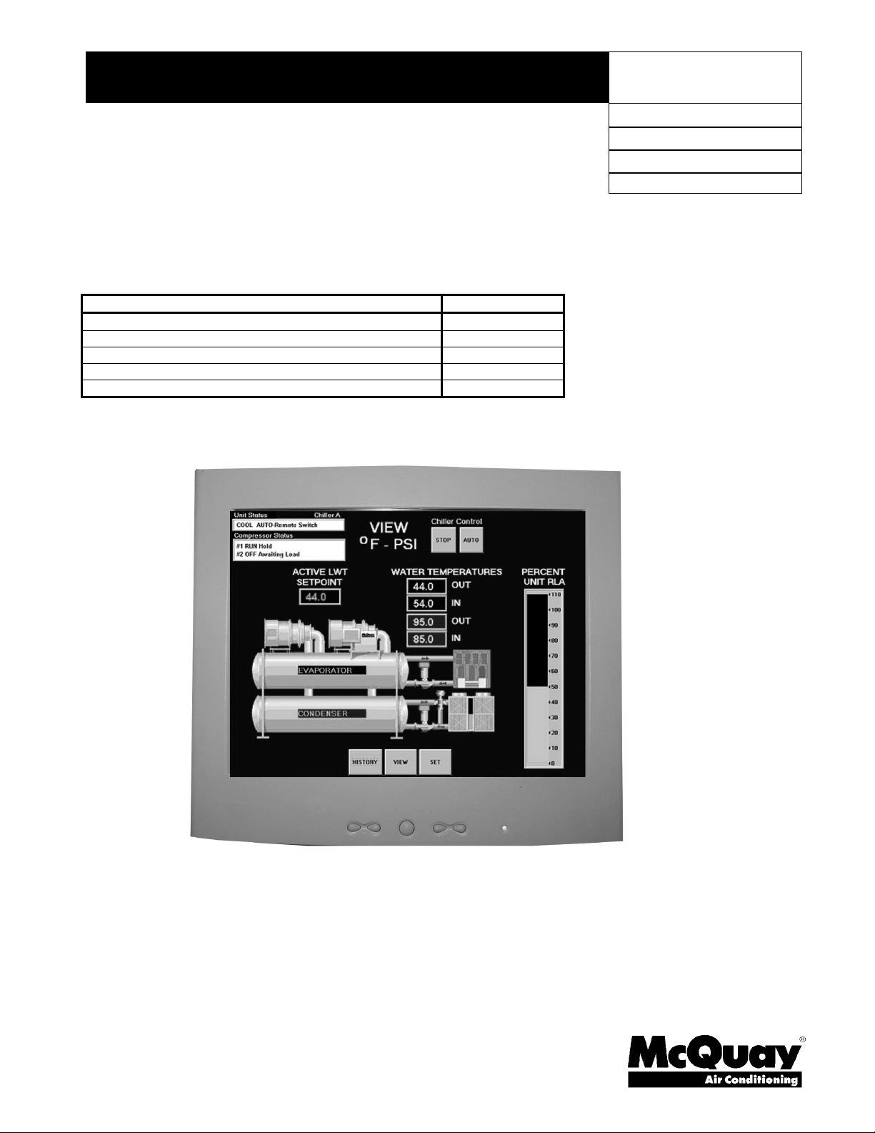
Installation, Operating and Maintenance Manual
Field Installation Procedure for MicroTech II
Centrifugal Chiller Control Panel Retrofit Kit
Description Kit Part Number
WSC 50/60 Hz, All Models with Touch Screen Panel 300042762
WSC 50/60 Hz, All Models without Touch Screen Panel 300042763
WDC 50/60 Hz, All Models with Touch Screen Panel 300042764
WDC 50/60 Hz, All Models without Touch Screen Panel 300042765
Operator Interface Upgrade kit 50/60 Hz 300040547
IM 786
Group: Aftermarket Products
Part Number: 331357301
Effective: October 2005
Supersedes: January 2004
Page 2

2004 McQuay International
2 Field Installation Procedure IM 786
Page 3

Table of Contents
Introduction...................................................................................................... 5
Building Automation Systems (BAS) Interface .....................................................................5
Disassembly....................................................................................................... 6
Important Note on Downloading Settings..............................................................................6
Existing MicroTech Control Panel.......................................................................................10
Lube Box (MT 100 with PSC oil pump motor shown)........................................................11
Installing the MT II Control Elements......................................................... 13
Install New Panels...............................................................................................................13
Enhanced Surge Protection..................................................................................................18
Install New Components......................................................................................................20
Sensor Locations..................................................................................................................22
Control Panel Connections..................................................................................................26
Check Out and Startup.................................................................................. 31
Table of Figures
Figure 1, MicroTech 200 Panel .............................................................................................6
Figure 2, Existing Data Record: MicroTech 200...................................................................7
Figure 3, Existing Data Record: MicroTech 100...................................................................9
Figure 4, Unit Control Panel, brackets and optional Touch Screen Panel ...........................15
Figure 5, Unit Control Panel, brackets and optional Touch Screen Panel ...........................16
Figure 6, Unit Control Panel and optional Touch Screen Panel mounting locations ...........17
Figure 7, Suction temperature sensor location.....................................................................18
Figure 8, Sensor Locations on unit (Models WSC/WDC)...................................................22
Figure 9, Partial front view of unit.......................................................................................23
Figure 10, Detail of sensor locations...................................................................................23
Figure 11, Sensor locations (Models PEH/PFH) .................................................................25
Figure 12, Unit Control Panel detail....................................................................................26
Figure 13, Unit Control Panel connections..........................................................................27
Figure 14, Compressor Control Panel detail........................................................................28
Figure 15, Compressor Control Panel connections..............................................................29
Manufactured in an ISO Certified Facility
Illustrations and information cover McQuay International products at the time of publication and we reserve the right
to make changes in design and construction at anytime without notice.
IM 786 Field Installation Procedure 3
2003 McQuay International
Page 4

4 Field Installation Procedure IM 786
Page 5

Introduction
These procedures must be performed only by technicians with training and experience on
Westinghouse/McQuay centrifugal water chillers including, but not limited to, MicroTech Series
100 and 200 controllers and MicroTech II (MT II) controllers.
Before commencing any actual replacement work, review the entire procedure, step by step, for the
unit being considered. Also, study the unit to pinpoint the location of the new control components.
This should help prevent difficulties during the procedure.
The procedure consists of:
1. Disassembling of the old control components
2. Installing the MT II control panels
3. Installing new sensors and rewiring.
4. Installing and configuring new software and checking unit operation.
Building Automation Systems (BAS) Interface
Determine if the new chiller controls will be required to tie into the building’s BAS. If so, verify
that the communication protocol is BACnet, L
for these protocols can be obtained separately and field installed on the controller. MicroTech II
cannot talk to an existing BAS through McQuay Open Protocol Master Panels (OPM, CVPC,
CSC, and direct connections) that may be on the job. Communication module part numbers are:
ONTALK, or Modbus. Communication modules
L
ONMARK: 350147401
BACnet: 350147404
Modbus: 350147402
IMPORTANT: Because the new MicroTech II controllers utilizes open, standard protocols listed
above, they are not compatible with legacy MicroTech system controls which utilize legacy,
proprietary McQuay Open Protocol. Therefore, the new MicroTech II chiller unit control panel is
not compatible with the existing MicroTech Chiller System Controller (CSC), Chiller Plant
Controller (CPC), MicroTech Monitor software, MicroTech Network Master Panels (NMP), or
MicroTech Remote Monitoring and Sequencing (RMS) panels. Your McQuay Representative can
help you plan the efficient management of your MicroTech and MicroTech II chiller equipment with
your building’s chiller plant or overall building automation system as your building needs change.
IM 786 Field Installation Procedure 5
Page 6
Disassembly
Important Note on Transferring Settings
Record all settings from the existing MicroTech 100 or 200 controller before de-energizing the panel
and removing it. Many of the settings will have to be changed from default later in the MT II
controller to configure the unit correctly. Forms are included on pages 6 and 7 to record settings.
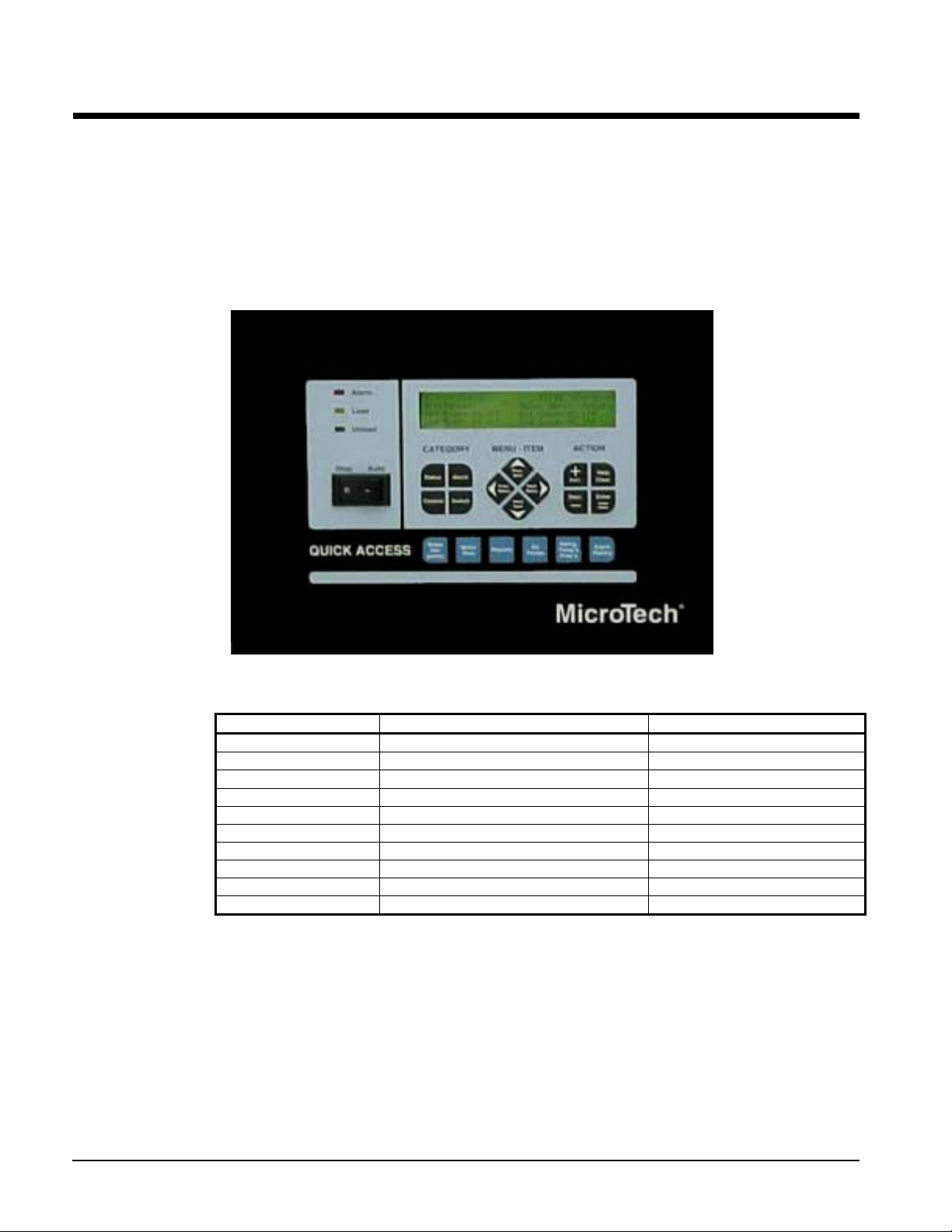
MicroTech 200
Figure 1, MicroTech 200 Panel
Perform the following steps to record setpoint data from the existing MicroTech 200 control. See
manual OM 200 for detailed information.
Action View Record/Ignore
Press Water Setpoints Screen 12, Water Setpoints Record
Press Next Menu Screen 13, Motor Setpoints Record
Press Next Menu Screen 14, Time/Date Ignore*
Press Next Menu Screen 15, Schedule Ignore*
Press Next Menu Screen 16, Schedule Ignore*
Press Next Menu Screen 17, Timers Setpoints Record
Press Next Menu Screen 18-20, Tower Setpoints Record
Press Next Menu Screen 21, Oil Setpoints Record
Press Next Menu Screen 22, Alarms Setpoint Record
Press Next Menu Screen 23, Lead/Lag, dual compressors Ignore
*The schedule function is not avaliable in the MTII
6 Field Installation Procedure IM 786
Page 7

Figure 2, Existing Data Record: MicroTech 200
MicroTech 200
Setting Value Setting Value
Menu 12, Water Setpoints S creen 2
Screen 1 Stage 1 On
Spt Source Stage 4 on
Local Spt Stage 2 On
Startup DT Stage 3 On
Shutdn DT Menu 20 Tower Valve Control
Screen 2 Screen1
Chw Reset Valve control
Max lvg Spt Valve Spt
Return Spt Valve Deadb
No Reset at 70°F
Reset Signal Max position
Max reset
Screen 3
Pulldn Rate Sample Time
Amb Lockout
Menu 13, Motor Setpoints PA Time
Screen 1 Screen 3
Amp Reset Min Start Position
Active Spt Max Start Position
Reset Signal
Min Amp Spt Max Pos At
Network Spt
Max Amp Spt Screen 1
Screen 2 Feed Spt
Soft load No Start Diff
Begin Amp Lim Htr On Diff
Ramp Time Menu 22, Alarms Setpoint
Menu 14, Time/Date
Screen 1 Low Evap Press Shutdown
Hh;mm;ss
Day
mm-dd-yy
Menu 15, Schedule High Discharge Temp Shutdown
Start-stop schedule
Menu 16, Schedule High Condenser Press Shutdown
Start-stop schedule
Menu 17, Timers Setpoints Motor Current Thres hol d
Screen 1 High Oil Feed Temp
Start to Start Low Oil Delta Temp
Evap recirc Screen 4
Stop to Start Low Net Oil Pressure
Menu 18 Pump Setpoints Low Disch Superht at Min RLA
Screen 1 High Disch Superht at Min RLA
Evap Pmp Screen 5
Cond Pmp Low Disch Superht at Max RLA
Menu 19 Cooling Tower Control High Disch Superht at Max RLA
Screen 1 Surge-High Suct Superht-St artinf
Tower Control Screen 6
Tower Stages Surge-High Suct Superht-Running
Stageup Time Evap Water Freeze
Stage Dn Time Cond Water Freeze
Stage Differential
N/A on MTII
N/A on MTII
N/A on MTII
N/A on MTII
N/A on MTII
N/A on MTII
N/A on MTII
N/A on MTII
N/A on MTII
N/A on MTII
Min position
Screen 2
Valve Type
Mod Limit
Max Change
Min Pos At
Menu 21, Oil Setpoints
Screen 1
Low Evap Press Unload
Low Evap Press Hold
Screen 2
High Discharge Temp Load
Screen 3
N/A on MTII
N/A on MTII
N/A on MTII
N/A on MTII
N/A on MTII
N/A on MTII
IM 786 Field Installation Procedure 7
Page 8
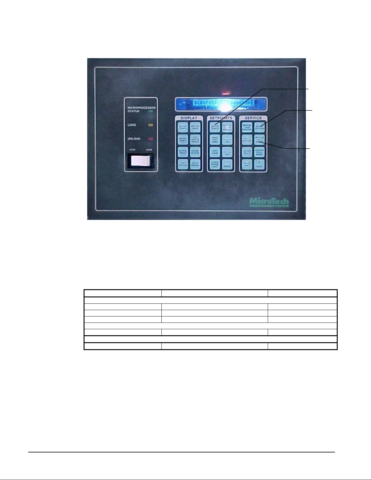
MicroTech 100
Setpoints reside in three locations on the MicroTech control. There are eight buttons under
the “SETPOINT” heading, only three of which have information to be recorded as shown
below. The buttons are pressed three times to access three different sets of data. Refer to
manual IM 403.
Setpoint
Menus
Set-up
Options
Service
Setpoint
Menus
1. There are thirteen settings under the Service Setpoint button, accessed by repeatedly
pressing the button.
2. There are 18 settings under the Set-up Options button.
Action View Action
SETPOINTS
Press WATE R TEMPERATURE View LWT, Reset, Res et Record Data
Press MAXIMUM AMP LIMIT View Amp Limit, Remote Limit, Si gnal Record Data
Press SOFT LOAD View Soft Load, Beginning Amps , Ramp Time Record Data
SERVICE SETPOINTS
Press 13 times View Setpoints Rec ord 2-13
SET-UP O PTIONS
Press 18 times View setpoint s Record 1-18
8 Field Installation Procedure IM 786
Page 9

Figure 3, Existing Data Record: MicroTech 100
MicroTech 100
Setting Value
SETPOINTS, Password Required
Press WATER TEMPERATURE
LLVG EVAP SPT
RESET LVG SIG This is a Read Only Value
RMT RESET SIG This is a Read Only Value
Press MA XI MU M AMP LIMIT
MAX AMP LIM
REMOT AMP LIN This is a Read Only Value
REMOT AMP SIG
Press SOFT LOAD
SOFT LOAD AMP
BEG AMP LIMIT
RAMP UP TIME
SET-UP OPTIONS, Password Required
RESET OPTIONS
MAX CHW RESET
ENT EVAP SPT
ENT EVAP TIMER
START MODE
START UP DELTA –T
SHUTDOWN DELTA -T
STARTTO START TIME
STOP TO START TIME
LOAD DELAY
COND PUMP TMR
TWR STG 1 ON
TWR STG 1 OFF
TWR STG 2 ON
TWR STG 2 OFF
ENABLE LAG
DISABLE LAG
DELAY TIMER
SERVICE SET-POINTS, Service Password Req’d
LOW MTR CURR
HOT GAS SPT
LOW OIL DELTA
CALC OIL STP
HIGH OIL FEED
LOW EVAP PRESS
LP OVERRIDE
HI DISCHARGE
HIGH SUCT RUN
HIGH SUCT OFF
HI COND PRESS
N/A on MTII
N/A on MTII
N/A on MTII
N/A on MTII
N/A on MTII
IM 786 Field Installation Procedure 9
Page 10

WARNING
Electric shock hazard. Disconnect all power sources to the control box.
Existing MicroTech Control Panel
Chiller may need to be pumped down to allow installation of new pressure transducers and new
mechanical high pressure switch before removal of old control panel. As in every case, make sure
there is water flow during pumpdown.
CAUTION
1. Service on this equipment must be performed by trained, experienced refriger ation
personnel familiar with equipment operat ion, maintenance, correct servicing
preocdedures, and the safety hazards inherent in this work.
2. Anyone servicing this equipment must comply with EPA requirements reg arding
refrigerant r eclaim a t ion and venting.
1. De-energize power to existing MicroTech (MT) panel (lock and tag out).
2. Check with VOM for presence of voltage in the MT panel. Isolate and de-energize if present.
3. Check for and disconnect any BAS communication from motherboard or display board.
4. Identify all external wiring to and from the MT panel. Mark as necessary. Factory wiring
should be labeled with wire numbers.
5. Remove all external wiring and conduit.
6. Remove all temperature sensors and discard. MT II uses all new sensors, 10k versus 3k on the
older units.
7. Isolate refrigerant and oil lines connected to MT panel. Remove and cap to prevent loss of
refrigerant and oil. Isolate the oil sump while there is still some pressure in the system to
prevent moisture from entering the tank. This is particularly important on R-134a systems.
8. Remove solenoid coil, wires, and conduit from oil cooler valve, liquid injection valve (if
present), and motor cooling valve (if present). Any valves that are not Sporlan brand will have
to be replaced. Older controllers used 115V solenoids coils, MT II use 24V solenoids coils.
Alternately, 115V to 24V interposing relays can be added to operate the existing valves.
9. Remove old control panel from chiller.
10. In most cases it is easier to leave the existing lube box on the unit and mount the new
compressor control panel adjacent to it. Two pieces of angle iron can be installed on the existing
lube box supports, extending out to provide a mounting location for the new panel.
10 Field Installation Procedure IM 786
Page 11
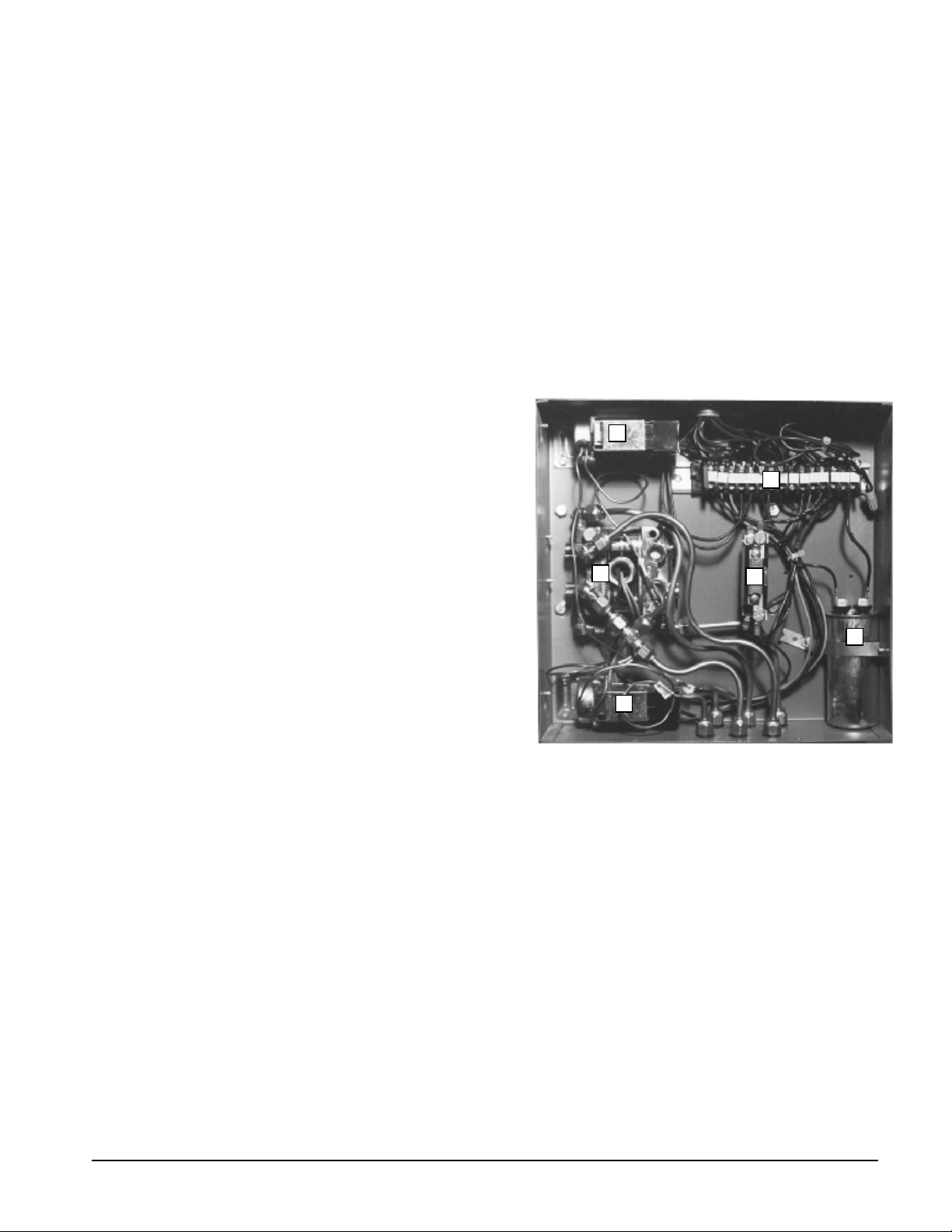
Lube Box (MT 100 with PSC oil pump motor shown)
There are two basic types of oil pump motors used on Westinghouse/McQuay centrifugal chillers.
Many early design chillers with all size compressors, and all chillers (including current production)
with compressor sizes CE050 and smaller use a Capacitor Start oil pump motor that has uses a
voltage relay. Chillers from approximately 1981 onward with compressor size CE063 and larger
use a Permanent Split Capacitor (PSC) oil pump motor which does not use the voltage relay. In
addition to the presence or absence of the voltage relay the two style motors use different overload
heaters and different capacitors. The same style oil pump motor will use slightly different value
capacitors when used in a 50 Hz application as opposed to a 60 Hz application.
To account for these differences some changes to the factory assembled compressor control panel
may be necessary as the kit is set up for a 60Hz PSC oil pump motor, and the chiller which the
upgrade kit is being installed in may be different. Details on the necessary changes are documented
in the following section.
1. Remove and discard oil pump contactor
(not shown). MT 200 has the pump
contactor in lube box, . MT 100 has
contactor in the control panel.
2. Remove Voltage Relay (not shown) if
present and discard. This is used only on
Capacitor Start oil pump motors, and not
on PSC oil pump motors. A new one is
included in the kit for mounting in the
compressor control panel.
3
4
6
5
3. Re-use Vane Close (VC) pressure switch.
4. Rewire terminal block as required and
document.
5. Remove and discard oil pump overload A
new overload is included in the
8
compressor control panel. This may need
to have its heater replaced with the
alternate. See following instructions.
6. Re-use SA/SB solenoid valve
7. Remove and discard oil pump capacitor(s) . A new capacitor is included in the compressor
control panel. This may need to be changed for one of the alternate capacitors, depending upon
the oil pump motor type and Hz. See following instructions.
8. Existing Oil Pressure (OP) switch can be re-used if desired. Wire NO contacts in starter MCR
circuit. MT 200 does not have this switch, the microprocessor senses the pressures and performs
this function.
7
IM 786 Field Installation Procedure 11
Page 12

If the chiller is a 60 Hz unit with a PSC oil pump then no changes to the compressor control panel are
necessary.
If the chiller is not a 60 Hz unit with a PSC oil pump, open the compressor control panel(s) and
make the following changes:
A. If the chiller is a 50 Hz unit with a PSC oil pump motor (unit will not have a voltage relay
in the lube box):
1. Remove and discard the p/n 7350767401 capacitor (35 MFD) in the panel and replace
with the included p/n 735067403 capacitor (60 MFD).
B. If the chiller is a 60 Hz unit with a Capacitor Start oil pump motor (Used on CE050
compressor which will have a voltage relay in the lube box):
1. Remove and discard the p/n 7350767401 capacitor (35 MFD) in the panel and replace
with the included p/n 330261502 capacitor (161 MFD).
2. Remove and discard the overload heater from the overload and replace with the
included p/n 735021578
3. Install the included voltage relay p/n 735020118.
C. If the chiller is a 50 Hz unit with a Capacitor Start oil pump motor (Used on CE050
compressor which will have a voltage relay in the lube box):
1. Remove and discard the p/n 7350767401 capacitor (35 MFD) in the panel and replace
with the included p/n 330261501 capacitor (200 MFD).
2. Remove and discard the overload heater from the overload and replace with the
included p/n 735021578
3. Install the included voltage relay p/n 735020118.
12 Field Installation Procedure IM 786
Page 13

Installing the MT II Control Elements
Install New Panels
Whenever possible, mount the MT II control panels in the same location as current production
WSC/WDC units. Mount the unit control panel on the evaporator where the old control panel was
and mount the compressor control panel adjacent to the existing (and remaining) lube box as shown
below.
MT II compressor control panel mounted to the
right of the existing lube box on angle-iron
extensions.
End view looking at the new compressor control
panel. The two angle-iron supports are visible on
the rear of the panel
MT II unit control panel and Touch Screen Panel
mounted on existing evaporator shelf. A small junction
box has been added to the top to facilitate connections.
View of the existing lube box with the angle-iron just
visible, inserted between the box and the box support.
Some chillers will not accommodate the compressor control panel mounted adjacent to the lube box,
so both MT II panels must be mounted on the evaporator.
Mount compressor control panel (on left) and unit control panel (on right) on the plate where the
Series 100 control panel was mounted. The plate will have to be re-drilled for mounting if both
panels are mounted next to each other (see picture on the following page). Fabricate brackets where
needed for vertical support of compressor control panel. If kit was purchased with an optional
Touch Screen Panel, drill and mount arm for display screen. See Figure 5 on page 16 for mounting
location on unit.
IM 786 Field Installation Procedure 13
Page 14

Note: The unit control panel has the
emergency stop/start switch located
on the left side, between the two
panels. The switch must be easily
accessible, so it must be moved,
ample space left between the panels
to access the switch, or the position
of the panels must be reversed.
Exploded views of the mounting of
the unit control panel and Touch
Screen Panel (TS) for WSC and
WDC vintage units can be found as
follows:
Touch Screen Compressor Box Unit Box
• Figure 3, WSC 050 - 126, WDC 050 – 126, except WDC 079-087 E36/C30 and E36/C36
• Figure 4, WDC 079-087 E36/C30 and E36/C36
Various mounting locations for the unit control panel are shown on Figure 5 on page 16.
Use existing MT Series 100/200 wiring diagrams, MT II wiring diagrams, and wiring details
enclosed in the kit for termination of wiring.
14 Field Installation Procedure IM 786
Page 15

Figure 4, Unit Control Panel, brackets and opt ional Touch Screen Panel
For WSC 050 - 126, WDC 050 – 126
Except WDC 079-087 E36/C30 and E36/C36
IM 786 Field Installation Procedure 15
Page 16

Figure 5, Unit Control Panel, brackets and opt ional Touch Screen Panel
WDC 079-087 E36/C30 and E36/C36
16 Field Installation Procedure IM 786
Page 17

Figure 6, Unit Control Panel and optional Touch Screen Panel mounting locati ons
IM 786 Field Installation Procedure 17
Page 18

Enhanced Surge Protection
Current software (late 2003 and after) supports “Enhanced Surge Protection”, which provides
improved protection against possible damage resulting from the compressor going into a surge
condition. The suction sensor is used to transmit temperature conditions to the controller. It is
important that the sensor be located in the correct position. If not, it must be relocated.
Figure 7, Suction temperature sensor location
18 Field Installation Procedure IM 786
Page 19

If the suction sensor is not in the correct location, complete the following steps.
WARNING
Refrigerant can cause asphyxiation, environmental damage, severe personal injury or death. Follow
EPA procedures for removing charge before continuing installation.
1. Be sure that the charge from the compressor has been removed following EPA or related
government regulations. The system pressure must be 0 psig to perform this modification.
2. Remove the existing temperature sensor and well. Discard the sensor.
3. Remove the suction elbow from the chiller unit.
4. Locate the center of the new port approximately 1 inch (2.5 cm) from the Victaulic coupling and
at the five o’clock position as viewed looking into the inlet cone.
5. Drill a 1.44 inch hole as shown.
6. Weld the ¾ NPT pipe coupling(p/n 735031434) in the new location.
7. Insert the suction temperature well (p/n047441511, use Loctite sealant*).
8. Install a new 10K temperature sensor (p/n 073007303) into the well.
9. Plug the original hole with the ¾ inch plug provided (p/n 735031649, use Loctite sealant*).
10. Clean and replace Victaulic gaskets if needed.
*Loctite 277 is recommended. 50ml part number 300040885, 250ml 300040884.
IM 786 Field Installation Procedure 19
Page 20

Install New Components
1. Chiller may need to be pumped down to allow installation of new pressure transducers and new
mechanical high pressure switch (steps 3 and 5, below) before removal of old control panel. As
in every case, make sure there is water flow during pumpdown.
2. Install new temperature sensors and connect to appropriate controller (compressor or unit).
Sensor p/n 073007203 are 90°
Sensor p/n 073007303 are straight
Extra temperature sensors are included to allow for various installation needs.
Oil sump temperature sensor may be p/n 0730007303 (straight) or p/n 330198003 (requires
well), depending upon the vintage of the oil pump. One of each is included for each compressor
control panel.
Unit Controller Temp Sensors
• Evap entering water temp
• Cond entering water temp
• Cond leaving water temp
• Liquid line temp
Compressor Controller Temp Sensors (one
set for each compressor on a chiller)
• Oil sump temp
• Compressor suction temp
• Compressor discharge temp
• Oil feed temp
• Evap leaving water temp
3. MT 200 units will have the correct high pressure and low pressure transducers for refrigerant
pressure and oil pressure sensing. New transducers are included for use on MT 100 units (blue
dot low-pressure range; red dot high-pressure range). Install transducers and terminate in
compressor control box. Oil pressure transducer will be installed on existing 1/4" line that fed
the old oil pressure transducer. This line may be shortened with 1/4" male flare fitting with
Schraeder valve brazed on the end.
4. Install new 24 VAC solenoid valve and cable on liquid injection solenoid valve (if present),
motor cooling solenoid valve (if present) and oil cooler solenoid valve. Terminate at compressor
control panel. If compressor has hot gas bypass purchase and install coils for solenoid
valves on HGBP assembly (solenoid coils not included in kit).
5. MT 200 units will have the correct mechanical high pressure switch (MHP) on discharge line.
New MHP switches are included for use on MT 100 units. Install switch if not already present,
run wiring in flexible conduit, and terminate at compressor control box. See “High Pressure
Switch Use” section to determine which switch you should use.
6. Install pLAN communications cables between unit controller and compressor controllers.
Sixteen feet of 3-conductor cable (074608901) is enclosed with each compressor control panel
for this purpose.
7. Re-install all conduits from lube box, motor starter, motor temperature (Guardistor)
protection, and water flow protection into compressor control panel and terminate wiring.
8. Ensure that correct components have been installed into compressor control panel (see
lube box section, pages 10 and 11). Re-wire lube box as required.
9. If applicable, re-install conduits from pump and /or tower controls, external start/stop or alarm
circuit into unit controller and terminate wiring.
10. If purchased, install Touch Screen Panel (TS) flexible arm and TS. Attach cable from TS to unit
control panel.
20 Field Installation Procedure IM 786
Page 21

Unit Controller External Inputs/Outputs
For Optional Functions
• External start/stop contacts (D.I.)
• Water Pumps start/stop contacts (D.O.)
• Tower Fans start/stop contacts (D.O.)
• External Chilled water temperature reset (A.I.)
• External Motor Amps reset (A.I.)
• Alarm contacts (D.O.)
• Tower fan VFD and/or bypass valve (A.O.)
Compressor Controller Wiring Connections
• Oil pump and oil heaters
• Motor starter wiring
• Oil cooler, liquid injection, and motor cooling
solenoid valves
• Motor temperature thermistors
• SA/SB solenoid valves
• Vane close switch
• Evap and cond water flow (pressure) switches
• Refrigerant pressure transducers
CAUTION
Mechanical high-pressure switch (MHP) and transducers must be installed on unit with MT II
upgrade. Mechanical high-pressure switch must be installed on high side (discharge pressure) above
the check valve and may not be installed on a valve that can be isolated from system per pressure
vessel per A.S.M.E. code.
IM 786 Field Installation Procedure 21
Page 22
Sensor Locations
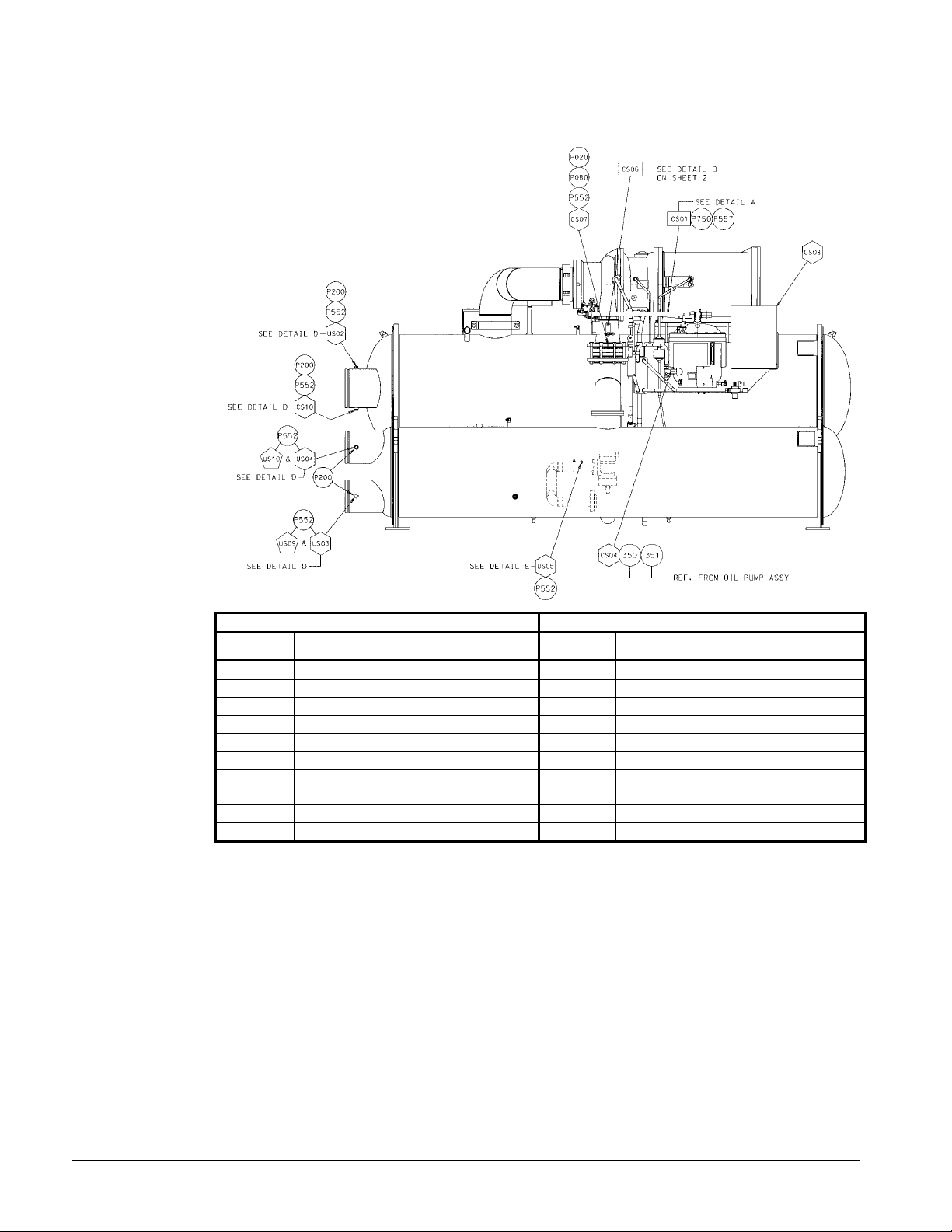
Figure 8, Sensor Locations on unit (Models WSC/ WDC)
UNIT CONTROL LER SENSOR LOCATION COMPRESSOR CONTROLLER SENSOR LOCATION
SENSOR
NUMBER
US02 EVAP. ENTERING WATER TEMP. CS01 OIL SUMP PRESSURE
US03 COND. ENTERING WATER TEMP. CS02 OIL FEED GAUGE PRESSURE
US04 COND. LEAVING WATER TEMP. CS03 EVAP. REFRIGERANT PRESSURE
US05 LIQUID LINE TEMPERATURE CS04 OIL SUMP TEMPERATURE
US09 Not used (Heat Recovery applications only). CS05 COMP. SUCTION TEMPERATURE
US10 Not used (Heat Recovery applications only) CS06 COND. REFRIGERANT PRESSURE
DESCRIPTION
SENSOR
NUMBER
CS07 COMP. DISCHARGE TEMPERATURE
CS08 % COMPRESSOR AMPS (STARTER)
CS09 OIL FEED TEMPERATURE
CS10 EVAP. LEAVING WATER TEMP.
DESCRIPTION
The illustration above is for a single compressor chiller. On dual compressor chillers the
two compressor controllers have identical sensor call-outs.
22 Field Installation Procedure IM 786
Page 23
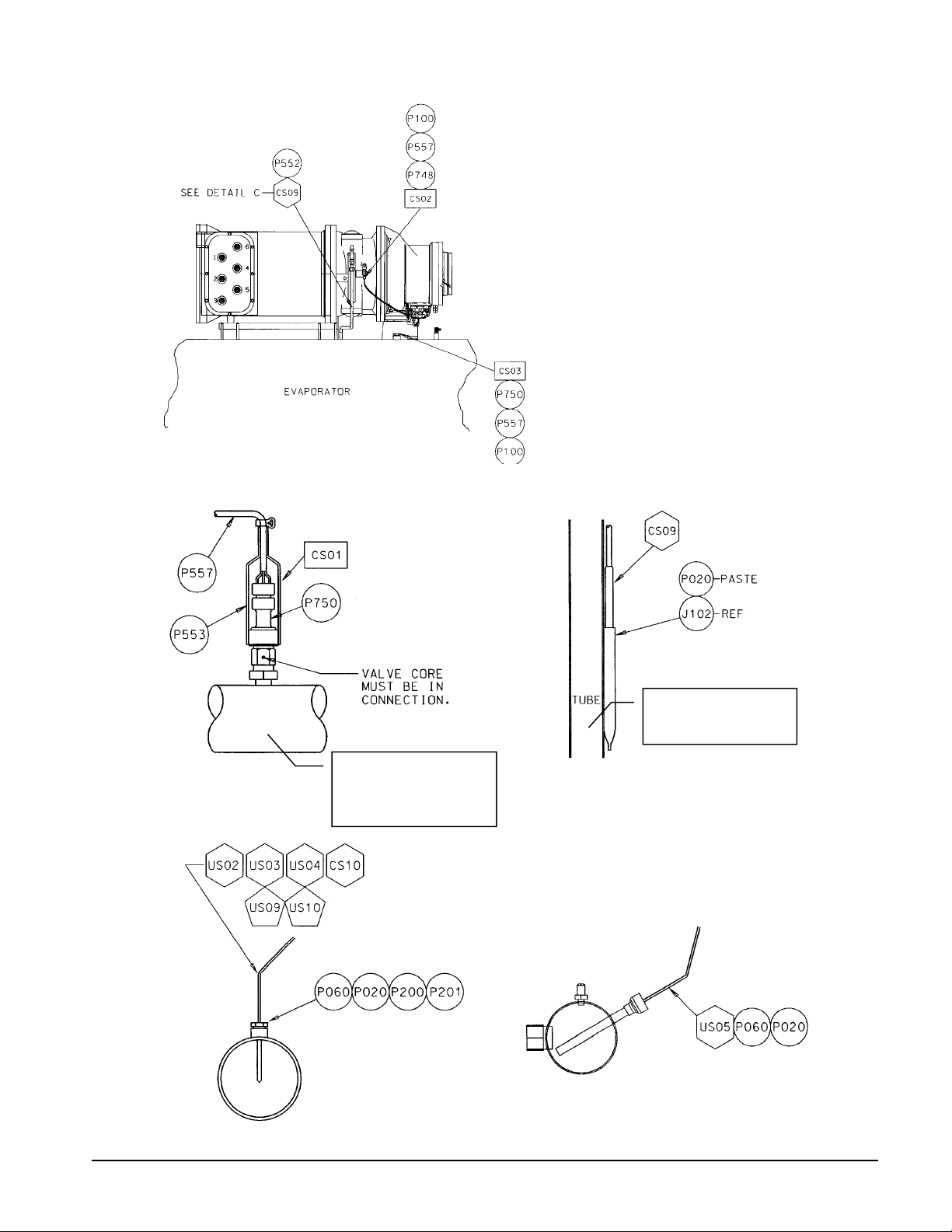
Figure 9, Partial front view of unit
Figure 10, Detail of sensor locations
Detail A
OIL PUMP VENT LINE,
CENTER-TOP OF SUMP
TO COMPRESSOR
Detail D
LINE FROM OIL COOLER
TO COMPRESSOR
FILTER
Detail C
Detail E
IM 786 Field Installation Procedure 23
Page 24
Detail of sensor locations, conti nued
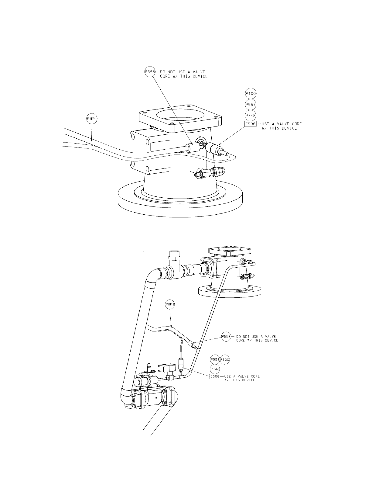
Detail B1 for MT 100/200 CS06, cond refrigerant pressure sensor & M HP l ocat i on
Detail B2 for MT 100/200 CS06, cond refrigerant pressure sensor location & MHP with
HGBP
24 Field Installation Procedure IM 786
Page 25
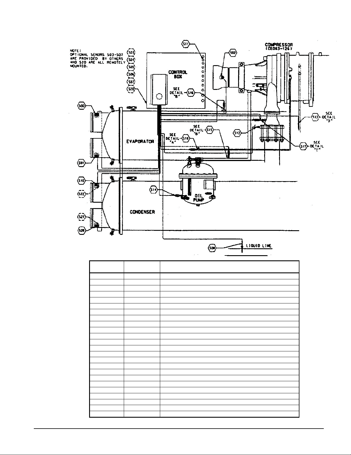
Figure 11, MT200 Sensor l ocat ions (Models PEH/PFH)
MT200
Sensor No.
S00 CS10 Evaporator Leaving W ater Temperature
S01 US02 Evaporator Entering Water Temperature
S02 CS05 Compressor Suct i on Temperature
S03 - External Chilled Water Reset (By Others)
S04 - External Motor Current Reset (By Others)
S05 - Refrigerant Leak Monitor Signal (By Ot hers)
S06 - Evaporator Water Flow Transm i tter Signal (By Others)
S07 - Condenser Water Flow Transm i t ter Signal (By Others)
S08 US05 Condenser Liquid Line Temperature
S09 US03 Condenser Entering Water Temperature
S10 US04 Condenser Leaving Wat er Temperature
S11 CS08 Percent Unit Amps
S12 CS07 Compressor Disc harge Temperature
S13 CS09 Oil Feed Temperature
S14 CS04 Oil Sump Temperat ure
S15 CS01 Oil Vent Pressure
S16 CS03 Evaporator Refrigerant Pres sure
S17 CS06 Condenser Refrigerant Press ure
S18 CS02 Oil Feed Gauge Pressure
S19 - Transducer Power Voltage Ratio
S20 - Outdoor Air Temperature
S21 US09 Not used (Heat Recovery Enteri ng Water Temperature)
S22 US10 Not used (Heat Recovery Leaving Water Temperature)
MT II Sensor
No
- Spare
Description
IM 786 Field Installation Procedure 25
Page 26

Control Panel Connections
The following figures give details of the control panels and how their input and output
connections are made.
Figure 12, Unit Control Panel detail
26 Field Installation Procedure IM 786
Page 27

Figure 13, Unit Control Panel connections
IM 786 Field Installation Procedure 27
Page 28

Figure 14, Compressor Control Panel detail
28 Field Installation Procedure IM 786
Page 29

Figure 15, Compressor Control Panel connections
IM 786 Field Installation Procedure 29
Page 30

High Pressure Switch Use
Included in the MicroTech II Retrofit Kit are two different model high pressure switches.
074796301 - SPST-NC switch that trips(opens) at 180psi +/-7psi and resets at 125psi +/- 10psi.
074796302 - SPST-NC switch that trips(opens) at 190psi +/-7psi and resets at 135psi +/- 10psi.
The use of either component should be determined by the rating of the relief valve on the condenser.
It is required that the pressure switch trips at a maximum pressure of 90% of the rated relief valve
setting that is installed on the chiller. It is desirable to select the lower rated pressure switch if it is
suitable to your application.
For the use of the 190psi pressure switch, the relief valve must be rated at 212psi or greater. For the
use of the 180psi pressure switch the relief valve must be rated at 200psi or greater relief pressure.
The 190psi pressure switch allows a little more operating room in the case of running higher saturated
condenser temperatures.
30 Field Installation Procedure IM 786
Page 31

Check Out and Startup
Disconnect motor leads from compressor before beginning check, test, and start to prevent
compressor from starting during start-up. Failure to do so can cause equipment damage.
1. Set dip switches on controllers.
CAUTION
Chiller Comp 1 Comp 2
A
Six Binary Switches: Up is ‘On’, indicated by ‘1’. Down is ‘Off’, indicated by ‘0’.
125678
100000 010000 101000 011000 111000 000100
Unit
Controller
Reserved
Operator
Interface
Reserved
2. Re-check all wire terminations to verify they are landed correctly.
3. Power up 115 volt circuit.
4. Check for proper voltages.
5. If the unit controller and compressor controller(s) have not been pre-loaded with software
contact Parts Tech Group @ 763-553-5403 for assistance in obtaining the necessary equipment
to load software into the controllers. This will also involve loading software into the optional
Touch Screen Panel. Input the specific chiller operating and equipment protection parameters
previously recorded from the old controller, after reviewing and checking against factory
defaults and current system design conditions.(See instructions in OM CentrifMicro II for
procedure).
CAUTION
Each of the MicroTech controllers must have compatible software versions(the latest version is
always recommended), including the Touch Screen software and UCM module. Controllers trying to
communicate with mixed software versions will result in corrupt data and may cause unexpected
events, such as random output energizing and possible compressor damage. Always follow proper
download procedures and check software versions on all controller devices and Touch Screen before
attempting to operate the chiller.
6. Check operation of all safety and operating controls.
7. Dry run starter.
8. Re-commission chiller.
The following are trademarks or registered trademarks of their respective companies: BACnet
from ASHRAE; L
ONMARK and LONWORKS from Echelon Corporation; Loctite from Loctite
Corporation, Sporlan from Sporlan Valve Company, Victaulic from Vitaulic Company, and
Guardistor, MicroTech, MicroTech II, Open Protocol, and Protocol Selectability from McQuay
International.
IM 786 Field Installation Procedure 31
Page 32

32 Field Installation Procedure IM 786
Page 33

Page 34

This document contains the most current product information as of this printing. For the most current product
information, please go to www.mcquay.com.
(800) 432-1342 • www.mcquay.com IM 786 (01/04)
 Loading...