

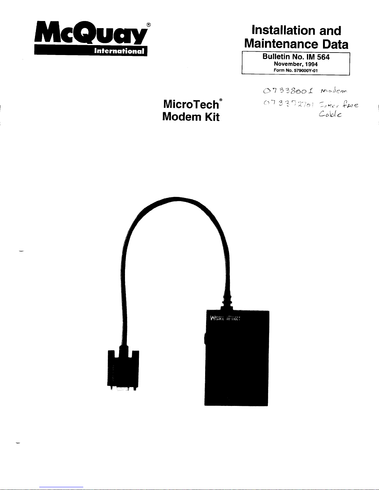
Page 1
Page 2
Page 3
This manual provides information on the components, installation, and service information for the
MicroTech”
Modem Kit. This new modem kit (part number 0072140601)
replaces part numbers 06680478-01 and 06702848-01
previously offered. The
MicroTech
Modem Kit, in conjunc-
tion with
MicroTech MonitorTM
software, allows the monitor-
ing of various
MicroTech
panels and controllers from a
remote or off-site location. See the list below for the
Micro-
Tech controllers that can accommodate a modem.
9
Network Master Panel (NMP)
l
Series 200 Application Specific Controller (ASC-200)
General Description
.
.
.
.
.
.
.
.
.
.
.
Loop Water Controller (LWC)
Application Specific Controller (ASC)
Remote Monitoring and Sequencing Panel (RMS)
Remote Monitoring and Control Panel (RMC)
Chiller System Controller (CSC)
Chiller Plant Controller (CPC)
Centrifugal Chiller Unit Controller
Reciprocating Chiller Unit Controller
Self-contained Air Conditioning Unit Controller
Screw Chiller Unit Controller
Applied Rooftop Unit Controller
Component Data
The main components of the
MicroTech
Modem Kit include
a modem, an interface cable, a U-shape and L-shape
bracket, and a ?&inch foam gasket.
Modem
The modem, shown in Figure 1, is a US Robotics”
World-
PortTM 14.4K
Fax/Data modem. A modem allows com-
munications between a
MicroTech
controller or a network of
controllers and a remote PC (not in the same location as
the controller). This is done by connecting the modem to a
phone line. The person wanting to monitor the controller(s)
then dials the phone number assigned to the modem.
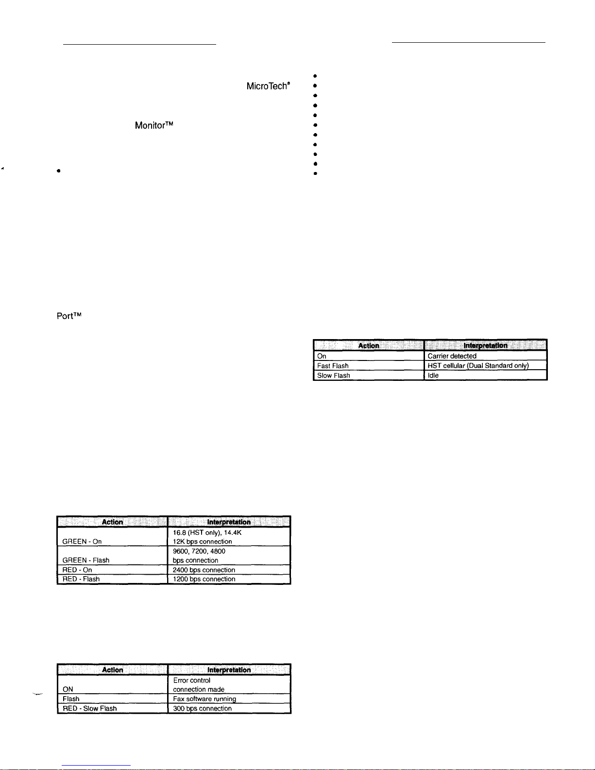
The modem has four feedback
LEDs,
a nine-pin female
extension cable, a phone jack, and an AC adapter jack.
Note: To monitor
MicroTech
controller(s) via the use of
a modem, your PC must be equipped with a modem and
the appropriate
MicroTech
Monitor software package.
Feedback
LEDs
The Feedback
LEDs
show the status of the modem.
The HS
LEDs
refer to the modem’s connection speed.
There are two HS
LEDs,
one green and one red. The
LEDs
are both located under the heading
“HS”
on the modem
(see Figure
1).The
LED will either stay on or flash (see
Table 1 for LED interpretation).’
Table 1. HS LED lnterpretation
The
ARQ/FAX
LED refers to error control or fax opera-
tions. The LED will either stay on or flash. ARQ stands for
Automatic Repeat Request. If an error occurs, the modem
will detect it and retransmit the data (see Table 2 for LED
interpretation).’
Table 2. ARQ/FAX LED Interpretation
The CD LED refers to carrier detect. The term “carrier” is
defined as the following according to the US Robotics
WorldPort
High Speed Modem User’s Guide: “A continuous
frequency that can either be modulated or impressed with
another information-carrying signal. These carriers are
generated and maintained by the modem via transmission
lines of the telephone company.” Table 3 shows the CD LED
interpretation.’
Table 3. CD LED lnterpretation
The LB LED refers to low battery. In all
MicroTech
applications, a battery is not used. The power plug provides
power to the modem. If the LED is on, the power supply has
a low voltage and needs to be checked.
Extension Cable
The extension cable is an external cable that is hard-wired
to the modem. The cable is 12-inches long and is termi-
nated with a nine-pin female connector. The extension
cable attaches to the interface cable (see Figure
2),
and the
two are secured together by screw connections.
Phone Jack
The phone jack connects to an existing telephone line and
allows data transmission to an external PC to take place.
The jack’s location is on the side of the modem. A
quickconnector on the end of the telephone line connects to the
phone jack. By calling the telephone number and having the
correct PC software and modem, you can initiate com-
munications between the
MicroTech
controller(s) and your
PC.
AC Adapter Jack
The AC adapter jack is an entry point for AC voltage. The
jack’s location is on the top of the modem. A power plug
from the interface cable (see Figure 2) connects to the jack
and sends the AC voltage to the modem.
Page 3 I IM 564
Page 4

Figure 1. US Robotics@
WorldPortTM
Modem (14.4K)
Top View
geedback LEd’s
Phone Jack
Side View
Figure 2. Interface Cable
Interface Cable
The interface cable connects to the modem’s extension
cable and the
MicroTech
controller. Figure 2 shows the
interface cable. The interface cable has a nine-pin male
connector terminated on one end. This male connector
attaches to the extension cable’s nine-pin female connector.
The connectors are held securely in place by screw
connections.
On the other end of the interface cable are a power wire,
an AMP connector, a power plug, and a 34-call initiate
connector.
Power Wire
The power wire is a red, 22 AWG wire. This wire delivers
DC voltage to the modem when connected to a 12-17 VDC
source in the
MicroTech
controller.
AMP Connector
The AMP connector attaches directly to a
MicroTech
controller’s communication port A. By connecting the AMP
connector, you allow communications from the controller to
flow through the cables and into the modem.
Note: The modem will not operate unless the AMP connector is connected. The modem signal and ground connections are made through the AMP connector.
Power Plug
The power plug connects directly to the modem’s AC
adapter jack. This plug delivers AC voltage to the modem
when the
MicroTech
controller is powered up.
Note: The modem must be powered up with the controller. The modem cannot use a separate power supply.
34-Pin Call Initiate Connector
The
34-pin
call initiate connector attaches to the Analog
Inputs socket in a
MicroTech
controller when the controller
initiates calls through the modem. This feature is used only
when the modem is connected to a Modem Alarm Unit
(MAU).
1
WorldPortTM
High Speed Modems User’s Guide:
(Skokie, IL: US Robotics@, Inc.
1993),
p. l-5
h
~
Power Plug (To AC Adapter Jack)
To Extension Cable---
(To MicroTech Controller
PoR
A)
Power Wire
To 12-l 7VDC Source
34-Pin Call
.-- -~
Initiate Connector
Pin 1
I
IM 564 / Page 4
Page 5

Installation
-
The installation procedure for the modem kit consists of the
interface cable to the controller, and connecting cables,
following: mounting the modem to a controller, wiring the
connectors, and the phone line to the modem.
Mounting the Modem
To mount the modem in a control panel, use the mounting
packet provided with the modem kit.
A U-shaped bracket or an L-shaped bracket included in
Figure 4. Modem Dimensions
the packet fits around the modem and holds it in place in
the panel. Because of the shape of the modem, a
X-inch
thick foam gasket is placed between the bracket and the
modem. Locate an area in the panel that will fit the
bracket’s screw holes. Refer to the product-specific installation manuals for details on where the modem should be
mounted. Place the modem and foam gasket inside and the
U-shaped or the L-shaped bracket. Secure the modem and
bracket to the panel or controller by using the screws
provided.
Note: Make sure that the
LEDs
on the modem are fac-
ing out.
Wiring the Interface Cable
Wiring the interface cable involves finding the power source
for the power wire. The red power wire must be connected
to a 12-l 7 VDC power supply inside the
MicroTech
Panel.
Can cause damage to the controller.
Voltage surge or short.
Power to the controller should be turned off when connecting the power wire to prevent shorting out the power
supply or having a sudden voltage surge.
On
NMP,
RMS, or RMC controllers, pin 8 on the
AUX/OUT
connector strip will provide approximately 13
VDC (see Figure 5). A factory wired pigtail on the
AUX/OUT
connector with a crimp-style socket is provided. The power
wire is then inserted into the pigtail socket and crimped.
If the
MicroTech
Panel has a field wiring terminal that is
connected to a 12-l 7 VDC power supply, the power wire is
connected to that terminal. Refer to Table 4 for power supply field wiring terminals in the various
MicroTech
control-
lers that supply
12-1
7 VDC.
1
3.8”
Table 4. Power Supply Terminals (12-l 7 VDC)
Applied Rooftop
Screw chiller
Reciprocating chiller
Centrifugal chiller
Application Specific Controller
(AX)
Self-contained Air Conditioning (SCAC)
Loop Water Controller (LWC)
Chiller Plant Controller
Series 200 Application Specific Controller
TB6-42
TB4-41
TB7-146
Terminal 67
TB3-25
or
TB3-26
12 VDC terminal
TS2-13
TS2-13
(ASC-200)
I
13 VDC teninal
Chiller System Controller
13 VDC terminal
Note: Measure the voltage at the field wiring terminal
.
before
connecting the power wire to ensure the proper
voltage is present.
Page 5
/
IM 564
Page 6

Connecting the Cables and Connectors
There are several connections that take place once the
interface cable wiring is complete. They are as follows:
interface and extension cables, AMP connector, power
plug, and the 34-pin call initiate connector (if necessary).
Interface Cable/Extension Cable
Both the interface cable and the extension cable have
9-pin
connectors. The interface cable has a nine-pin male con-
nector that fits into the extension cable’s female connector.
Place both cable connectors so that the pins on the male
connector align with the sockets on the female connector.
Slide the two connectors together and secure them by
tightening the screws on the extension cable connector.
Note: Be careful when tightening the screws on the
connector. Do not turn one screw more than two rotations
before turning the other screw. This will prevent damage to
the pins and the connectors.
AMP Connector
The AMP connector attaches to the communication port A
of a
MicroTech
controller (see Figure 4). Align the AMP
connector with the port A connector on the
MicroTech
con-
troller. Insert the AMP connector into port A. The AMP con-
nector included with the kit will connect with all modem
compatible
MicroTech
controllers except the Application
Specific Controller (ASC). The ASC has a Phoenix-type
connector. If the modem is connected to an ASC, an
adapter cable must be used to connect to port A. The
adapter cable is available by purchasing the
MicroTech
PC
Communications Cable Kit.
Note: The AMP connector must be connected to the
controller before the modem will operate. The modem signal and power ground connections are made through the
AMP connector.
34-Pin Call Initiate Connector
The 34-pin call initiate connector plugs into the Analog
Inputs port of a Modem Alarm Unit (MAU) controller. If the
modem is not connected to a MAU, coil the unused cable
and secure it to the interface cable housing.
Power Plug
The power plug connects to the AC adapter jack on the top
of the modem. Insert the male end of the power plug into
the AC adapter jack on the modem. This allows voltage to
get to the modem when all other conditions have been met.
Phone Jack
The phone jack is the modem’s outside communications
port. A telephone line connects to the jack so that outside
communications can take place. Align the telephone line
connector with the phone jack on the modem. Push the
telephone line connector into the jack until a clicking sound
is heard. This clicking sound ensures that the telephone
line connector is secured in place inside the phone jack.
Figure 4. MicroTech Controller (200 Series)
AUWOUT CONNECTOR STRIP
n
Modem Configuration
The modem configuration consists of the port speed, con-
nect speed, and configuration string. The modem configuration is set at the factory and should be ready for use.
Port/Connect Speed
Changing Con
troller
Port Configuration
The port speed is the speed at which the modem talks to
the
MicroTech
controller. The connect speed is the speed at
which the modem first communicates and then connects to
the
MicroTech
port. The port speed follows the connect
speed when flow control is off. For example, if you call into
the modem at 2400 bps, even though the modem is a
14.4K
bps, it will automatically switch the connect and port
speeds to 2400 bps.
MicroTech
controller’s port can be set to 300, 1200,
2400, 4800, and 9600 bps (bits per second). If you want to
leave the
MicroTech
controller port speed at the current
setting, you must know that setting when calling into the
modem.
The controller port configuration can be changed in three
different ways. The first is by direct changing on a controller’s keypad display. The second is from a Monitor package
“user screen.” The third way is by a detailed procedure
using the Monitor program.
When using a Remote Monitoring and Sequencing Panel
(RMS) or a Remote Monitoring Control Panel (RMC), the
keypad display can be used to change the port configu-
ration. Refer to Bulletin NO. OM 118 (RMS) or Bulletin NO.
OM 121 (RMC) for more information.
IM 564 I Page 6
Page 7

Also, some Monitor packages allow the changing of the
port configuration from a “user screen.” Consult your Monitor user’s manual or contact your McQuay Service representative for more details.
If you do not have the ability to change the port configuration by the use of a keypad or a “user screen,” perform
the following procedures.
Setting up Communications
Use a PC with the appropriate Monitor software.
1.
Directly connect an IBM compatible PC to port A of the
controller by using the PC cable from the PC Communications Cable Kit. The PC Communications Cable Kit
is available from McQuay International.
2.
3.
4.
Access the
MicroTech
Monitor software by typing run
at the
(C:\>)
prompt.
Press <Enter>.
Press <Enter> at the prompt, “Press
<Esc
to bypass
Communications Initiation,
<Enter>
to continue..:’
This will begin communications between the PC and
the controller.
Note: If communications does not begin, contact
your McQuay Service representative for more detailed
information.
Reading the Port A Speed
Once communications begin, the Main Menu appears on
the PC screen.
1.
2.
3.
4.
Press F7 Support Menu to access the Support Menu.
Press
F1
Read/Write Memory from the Support Menu.
This will bring up the Read/Write Memory screen.
Type “B” followed by the address of the controller you
are connected to. This sets up the box address. For
example: If you are connected to the level-l controller,
type in B0000. The address
“00.FF”
will also work for
direct connection.
Type in R8010 for a 100 series controller or
R0A10
for
a 200 series controller to find the controller port speed.
Refer to the lists below for more information on 100
and 200 series controllers.
.
.
.
.
.
.
.
.
.
.
.
.
.
100 Series Controller
Chiller Plant Controller (CPC)
Application Specific Controller (ASC)
Centrifugal Chiller Unit Controller
200 Series Controller
Network Master Panel (NMP)
Application Specific Controller 200 (ASC-200)
Loop Water Controller (LWC)
Remote Monitoring and Sequencing Panel (RMS)
Remote Monitoring and Control Panel (RMC)
Chiller System Controller Panel (CSC)
Self-contained Air Conditioning Unit Controller
Reciprocating Chiller Unit Controller
Screw Chiller Unit Controller
Applied Rooftop Unit Controller
Writing the new Port A Speed
The speed of the controller port will be shown in a hexadecimal form such as
9B.
The first digit (9) is the port B
speed and the second digit (B) is the port A speed. See
Table 5.
Type
W8010
for a 100 series controller or
W0A10
for a
200 series controller to change the controller port
speed.
A prompt on the screen will ask, “New Value for
00.00 (Box Address), 8010 or
[0A10]
(Memory Lo-
cations) or <ENTER> for no change.”
Select the speed needed using Table 5.
If the port speed was originally B6, the speed of
port A would be 1200. If the speed of port A should be
9600, you would type BB. This would set the port
speed to 9600 baud.
Type the new port speed (for example, BB).
Press <Enter>.
Never change the port B baud rate.
Will cause loss of communications with the network.
The users should not change the port B baud rate under
any circumstance or they will lose communications with
the rest of the network.
Table 5. Controller Communications Port Speeds.
I”~’
msi Rarte
I
I
,,,;.i--
~~
-1
300
I
4
I
1200
6
2400
8
4800
9
Resetting the Software
After entering the port speed, the controller needs to be
reset. The controller can be reset by performing a Software
Reset. Perform the execution of the Software Reset on the
Read/Write screen.
Type
W0204
(program code for Software Reset).
Press
<Enter>.
A prompt on the screen will ask, “New
Value for 00.00 0204 or <ENTER> for no change.”
Type an even number (0,2,4,6...) at the command. An
even number allows the program to reset and keep
running, an odd number (1,3,5...) stops the program
from running.
Press <Enter>. This stores the new port speed.
Correcting the Checksum
After the new port speed is stored, the Program Checksum
needs to be corrected. The Program Checksum must match
the EOS Checksum in order for the program to run. Perform
the following steps to change the Program Checksum.
These steps are also performed from the
Read/Write
screen.
1.
Type R8002 (100 series controller) or ROA02 (200
series controller) to read the EOS Checksum. The EOS
Checksum is shown in hexadecimal form. Write down
or remember the EOS Checksum.
Page 7
/
IM 564
Page 8

Type
W8001
(100 series controller) or
0A01
(200 se-
ries controller) to change the Program Checksum. A
command on the screen will ask, “New Value for
00.00
W8001
or
[0A01]
or <ENTER> for no change.”
Type the same hexadecimal value that was displayed
for the EOS Checksum.
Press <Enter>.
After entering the new Program Checksum, the
controller needs to reset. Follow the same Software
Reset procedure listed in steps 1-4 in the “Resetting
the Software” section above.
Press the F10 key to exit the Monitor program.
The modem configuration string is an AT command that
allows the modem to be compatible with
MicroTech
controllers. This configuration is set at the factory. If a problem with
configuration occurs, the configuration string may need to
be reset. To reset the string, a PC using the correct communications software is needed. Refer to the US Robotics,
WorldPort User’s Guide for more information on resetting
the string.
The following AT command is used to configure the
modem:
AT&FS0=1
B0Q1 E0&D0&W.
Table 6 explains
each command of the string.
Y
&IL
Table 6. AT Command Definitions
Note: For high speed modems, flow control must be
disabled to make the modems
MicroTech
compatible. In the
WorldPort 14.4K
modem, flow control is disabled as a factory default. No additional configuration is needed beyond
AT&F.
Remote Access
Using a PC and communications software, the modem can
be set up to be configured by a remote modem. This can be
helpful in troubleshooting modem operations. This enables
the user to call into the modem from a remote site and
change the configuration. For complete instructions on how
to perform Remote Access, refer to the US Robotics
WorldPort
High Speed Modems User’s Guide (Appendix E).
IM
564 / Page 8
Page 9

Page 10

Troubleshooting Power Problems
The modem interface cable receives 12-17 VDC from the
MicroTech
controller. A red power wire connects directly to
the
MicroTech
controller. A power plug on the interface
cable delivers AC voltage to the modem. If a problem with
powering up the modem occurs, the following troubleshooting items may help repair the problem.
The Modem Does Not Power Up.
Cause:
The red power wire is not connected to a 12-17
VDC supply in the
MicroTech
controller.
Solution: Refer to the product-specific installation manuals
to find a proper voltage supply in the
MicroTech
controller.
Cause:
The red power wire is improperly connected to
the
MicroTech
controller voltage supply.
Solution: Check the connection to the power supply.
Cause:
The power plug is not connected to the modem.
Solution: Connect the power plug to the AC adapter jack
on the modem.
Cause:
The interface cable internal wiring may be miswired or have a poor solder/connection point at
the power plug.
Solution: Measure the resistance (ohms) with a DVM
(Digital Voltmeter) to verify the correct wiring.
Cause:
The AMP connector is not plugged into the
MicroTech
controller’s port A.
Solution: Plug the AMP connector into port A of the
Micro-
Tech controller.
Cause:
The AMP connector is miswired or has a poor
connection.
Solution: Measure the resistance (ohms) using a DVM
(Digital Voltmeter) to verify the correct wiring.
Use the Wiring diagram in Figure 5.
Cause:
The interface cable is not properly connected to
the modem extension cable.
Solution: Reconnect the interface cable to the extension
cable.
Cause:
The interface cable may have a broken or
pushed in male connector pin.
Solution: Disconnect the interface cable and inspect for
broken or pushed in pins.
Troubleshooting Communications
Problems
If communications to the modem is unsuccessful or lost,
the following troubleshooting items may help in repairing
the problem.
The External Computer Cannot Communicate with the
MicroTech
Controller through the Modem.
Cause:
The phone line is not connected to the phone
jack on the modem.
Solution: Connect the phone line to the modem’s phone
jack.
Cause:
The AMP connector is not properly connected to
the
MicroTech
controller’s port A.
Solution: Reconnect the AMP connector to port A of the
controller.
Cause:
The AMP connector is miswired or has a poor
connection.
Solution: Measure the resistance (ohms) using a DVM
(Digital Voltmeter) to verify the correct wiring.
Use the wiring diagram in Figure 5.
Cause:
The connect/port speed does not match the
MicroTech
controller’s port speed.
Solution: Retry connect speeds until the proper speed is
found.
Cause:
The configuration string of the modem is
incorrect.
Solution: Re-enter the configuration string using a PC and
the correct communications software (see Table
5).
Cause:
The communications password is incorrect.
Solution: Enter the correct password in the Monitor pro-
gram and try again or contact McQuay Service.
If a problem still exists after performing the trouble-
shooting items, the modem may be defective.
IM 564
/
Page 10
 Loading...