

Page 1

Installation Manual
Digital Variable Multi Air Conditioner
MDS 30 – 70A(R)
MDS 80 – 320B(R)
5MDS 50 – 500B(R)
Page 2

Page 3

Installation Manual IM-MDS_(i) i
The data and suggestions in this document are believed current and accurate at the time of publication, but they
are not a substitute for trained, experienced and professional service. Individual applications and site variations
can significantly affect the results and effectiveness of any information, the reader must satisfy him/herself
regarding the applicability of any article and seek professional evaluation of all materials. McQuay disclaims any
responsibility for actions based on this document.
This installation manual is intended for and should only be used by qualified engineers/service
personnel. Installation and maintenance are to be performed only by qualified personnel who are familiar
with local codes and regulations, and experienced with this type of equipment.
Caution: Sharp edges and coil surfaces are a potential injury hazard. Avoid contact with them.
Warning: Moving machinery and electrical power hazard. May cause severe personnel injury
or death. Disconnect and lock off power before servicing equipment.
Page 4

ii Installation Manual IM-MDS_(i)
1.0 Safety Precautions...……………………………………………………………………………....1
1.1 Precautions before installation………………………………………………..………..1
1.2 Safety reminder on installation process...……………………………………………..1
1.3 Precautions on commissioning..………………………………………………………….1
1.4 Precautions for devices that use R410A refrigerant……………………………….....1
1.5 Other precautions……...…………………………………………………………………..2
2.0 Electrical Parameter……………………………………………………………………………..2
3.0 Installation Instruction……………………………………………………………….…………..4
4.0 Outdoor Unit Installation...………………………………………………………………………...4
4.1 Location and space of installation….…………………………………………………….4
4.2 Unit handling…………….………………………………………………………………….6
4.3 Unit installation…………..…………………………………………………………………6
4.4 Installation of master and slave unit……………………………………………………..6
5.0 Indoor Unit Installation…………………………………………………………………………7
5.1 Location and space of installation...……………………………………………………..7
5.2 Installation of MEX box………………………………….………………………………...7
5.3 Installation of MCCD series indoor unit………………………………………………….8
5.4 Installation of MCKD series indoor unit …………………………...…………………….8
5.5 Installation of MCMD series indoor unit ……………………………………………….10
5.6 Installation of MWMD series indoor unit ………………………………………………12
6.0 Piping Installation…………………………………………………………………………………13
6.1 Precautions for piping installation……………………………………………………....13
6.2 Refrigerant piping system………..………………………………………………..........14
6.3 Piping size, refnet and distributor selection….………………………………………15
6.4 Installation of refrigerant piping…………………………………………………...........18
6.5 Ball valve installation and operation.…………………………………………………19
7.0 Wiring Connection……………………………………………………………………………..…20
7.1 General wiring precautions……………………………………………………………20
7.2 Wire specification…………………………………………………………………………21
7.3 Electrical wiring connection……………………………………………………………21
7.4 Communication wiring connection……………………………………………………22
7.5 Dip switch setting……………………….………………………………………………..23
7.6 Auto restart setting……………………………………….............................................24
8.0 Air Leakage Test, Vacuum and Refrigerant Charge….…………………………………..….25
8.1 Air leakage test………………………...…………………………………………………25
8.2 Vacuum……………………………………………………………………………………25
8.3 Refrigerant charge…………..……………………………………………………………25
9.0 Commissioning………………………………………...….…………………………………..….25
9.1 Checking list before commissioning....…………………………………………………25
9.2 Commissioning record table.……………………………………………………………25
9.3 Common problems during commissioning.……………………………………………25
10.0 Unit Outlines and Dimensions….…………………………………..…………………………27
Table of Content
Page 5

Installation Manual IM-MDS_(i) 1
1.0 Safety Precautions
Please take note of the safety item stated below before and after the installation process:
1.1 Preparation before installation
Check the electrical power supply condition. Power supply shall meet the requirement of local rule and
regulation.
The tolerance of voltage shall be less than ±10% based on nominal voltage. It is not allowed to share the
same power cable through soldering as it will cause fluctuation of power supply.
Professional technician or engineer is needed to conduct the installation.
Follow the installation instruction in this manual. Improper installation may cause damage to the unit which
will then cause other accident to happen.
A solid base shall be built on the ground before installation of outdoor unit. The base shall be strong enough
to support the weight of the outdoor units. Counter measure should be taken against possible natural
disaster such as earthquake and typhoon.
Installation kits and protection kits shall be used to prevent injury.
1.2 Safety reminder on installation process
Do not touch the fins of heat exchanger. It may cause injury. Besides that, any damage on the heat
exchanger will reduce the heat exchange performance.
Secure the outdoor unit to avoid any vibration. The service panel and control box cover shall be closed
tightly to avoid any dirt and water from damaging the components.
Only air filter and heater provided/approved by factory shall be installed on the indoor units.
Action shall be taken to avoid refrigerant leakage during the installation process.
In case of any refrigerant leakage occur, open the window and door to improve ventilation and prevent fire
hazard.
Any electrical cable shall be kept away from water and humidity.
Do not change any settings of the protection devices unless instructed by factory.
Do not pull the electrical cable too tight, as it may cause the cable to break without notice.
Ensure the cable size is correct and sufficient to support the current and power consumption.
Unit must be earthed properly. Do not connect earth line with telephone line.
Indoor condensing water shall be drained away properly to avoid overflow. Insulation is needed for piping
connecting to the drain pan.
All units shall be handled and carried carefully during transportation.
After installation completed, the unit should undergo leakage test.
1.3 Precautions on commissioning
Power is to be supplied to the units for 12 hours before running them for the first time. This is to prevent any
damage of electrical components.
Avoid contact with power switch when hand is wet.
Do not remove the front panel or protection guard when the unit is in operation. The components running in
high speed may cause injury and damage.
Do not touch the refrigerant piping when the unit is running or just stop to avoid any injury.
Do not switch off the power supply immediately after the unit is off. Please wait for 5 minutes before shutting
down the power supply.
1.4 Precautions for devices that use R410A refrigerant
R410A is high pressure refrigerant. Do not use refrigerant piping of other type of refrigerant to prevent burst.
Do not use old refrigerator oil as it may contains large amount of chlorine that can cause the refrigerator oil in
R410A unit to deteriorate.
Use refrigerant piping that is made of phosphorus deoxidized copper and copper alloy seamless pipe.
Ensure the inner and outer surfaces of the pipes are clean and free of sulphur, oxide, dust, shaving particles,
oils, moisture and other contaminant.
Store the piping properly and keep both ends sealed until it is used to prevent dust and moisture.
Ensure that only liquid refrigerant is charged into the system as the composition of refrigerant is different in
gaseous phase.
Use ester oils, ether oil or small amount of alkylbenzene as the refrigerator oil to coat flares and flange
connection. Do not use mineral oil.
Use a vacuum pump with a reverse flow check valve. The vacuum pump oil may flow back into the
refrigerant cycle and cause the refrigerator oil to deteriorate.
Do not use refrigerant other than R410A.
Do not use tools such as gauge manifold, charge hose and etc which are not designed for R410A refrigerant.
Page 6
2 Installation Manual IM-MDS_(i)
1.5 Other precautions
Contact local distributor/manufacturer for assistance when there’s doubt on the installation process.
Do not charge in other type of refrigerant to the unit as this will damage the unit.
2.0 Electrical Parameter
All values given are for reference only. They shall be checked and selected to comply with local standards and
regulations.
MDS-A Series Outdoor
Model
MDS30-40A(R)
MDS50A(R)
MDS60A(R)
MDS50-60A(R)
MDS70A(R)
Power supply
(V/Ph/Hz)
220-240/1/50
380-415/3/50
Max. Breaker
Size (A)
25
30
40
15
20
Number of
Wires
3 3 3 5 5
Power Cable
Size (mm2)
6 6 6 4 4
MDS-B Series Outdoor
Model
MDS80B(R)
MDS100-
120B(R)
MDS150-
180B(R)
MDS200-
220B(R)
MDS240B(R)
Power supply
(V/Ph/Hz)
380-415/3/50
Max. Breaker
Size (A)
25
30
50
50
60
Number of
Wires
5 5 5 5 5
Power Cable
Size (mm2)
6 6 10
16
16
Model
MDS260B(R)
MDS280B(R)
MDS300B(R)
MDS320B(R)
Power supply
(V/Ph/Hz)
380-415/3/50
Max. Breaker
Size (A)
60
70
80
80
Number of
Wires
5 5 5
5
Power Cable
Size (mm2)
16 (Master) 10 (Slave)
Note: MDS 260-320B(R) is combined unit, consist of master unit and slave unit. There are two ways to connect the cable, either separate
connection or serial connection. For MDS 320, only separate connection can be used. For other combined units, it is recommended to use
serial connection.
5MDS-B Series Outdoor
Model
5MDS60B(R)
5MDS50B(R)
5MDS60-
70B(R)
5MDS80-
100B(R)
5MDS120B(R)
Power supply
(V/Ph/Hz)
220-240/1/50
380-415/3/50
Max. Breaker
Size (A)
40
15
20
25
30
Number of
Wires
3 5 5 5 5
Power Cable
Size (mm2)
6 4 4 6 6
Page 7
Installation Manual IM-MDS_(i) 3
Model
5MDS140-160B(R)
5MDS180-200B(R)
5MDS220B(R)
5MDS240B(R)
Power supply
(V/Ph/Hz)
380-415/3/50
Max. Breaker
Size (A)
40
50
60
60
Number of
Wires
5 5 5
5
Power Cable
Size (mm2)
10
10
10
16
Model
5MDS260-
280B(R)
5MDS300B(R)
5MDS320B(R)
5MDS340-360B(R)
Power supply (V/Ph/Hz)
380-415/3/50
Max. Breaker Size (A)
70
80
80
90
Number of Wires
5 5 5
5
Power Cable
Size (mm2)
Separate
6 (Master) 10 (Slave)
10 (Master) 10 (Slave)
Serial
16 (Master) 10 (Slave)
-
Model
5MDS380B(R)
5MDS400B(R)
5MDS420-
460B(R)
5MDS480-500B(R)
Power supply (V/Ph/Hz)
380-415/3/50
Max. Breaker Size (A)
100
100
125
125
Number of Wires
5 5 5
5
Power Cable
Size (mm2)
Separate
16 (Master) 10 (Slave)
16 (Master) 16 (Slave)
Serial
25 (Master) 10 (Slave)
25 (Master) 16 (Slave)
Note: 5MDS 260-500B(R) is combined unit, consist of master unit and slave unit. There are two ways to connect the cable, either separate
connection or serial connection. For 5MDS 320-360B(R), only separate connection can be used. For other combined units, it is
recommended to use serial connection.
MCCD/M5CCD Series Indoor
Model
10-15C
20-25C
28-30C
38-40C
50-60C
Power supply (V/Ph/Hz)
220-240/1/50
Number of Wires
3
Power Cable Size (mm2)
1.5
2.5
4.0
1.5
2.5
MCKD/M5CKD Series Indoor
Model
20-25A
30A
40A
50A
10-15C
20C
Power supply (V/Ph/Hz)
220-240/1/50
Number of Wires
3
Power Cable Size (mm2)
2.5
4.0
1.5
2.5
1.5
2.5
MCMD/M5CMD/MCMD/M5CMD Series Indoor
Model
15-25E
28E
40D
50D
62C
Power supply (V/Ph/Hz)
220-240/1/50
Number of Wires
3
Power Cable Size (mm2)
2.5
4.0
1.5
2.5
2.5
MWMD/M5WMD Series Indoor
Model
09-15G
20-25G
Power supply (V/Ph/Hz)
220-240/1/50
Number of Wires
3
Power Cable Size (mm2)
1.5
2.5
Page 8
4 Installation Manual IM-MDS_(i)
3.0 Installation Instruction
Kindly follow the installation steps shown below:
1. Choose the installation place
2. Install the outdoor and indoor unit
3. Install the piping and cable line
4. Perform leakage test
5. Vacuum the system and charge in refrigerant
6. Test run/commissioning
4.0 Outdoor Unit Installation
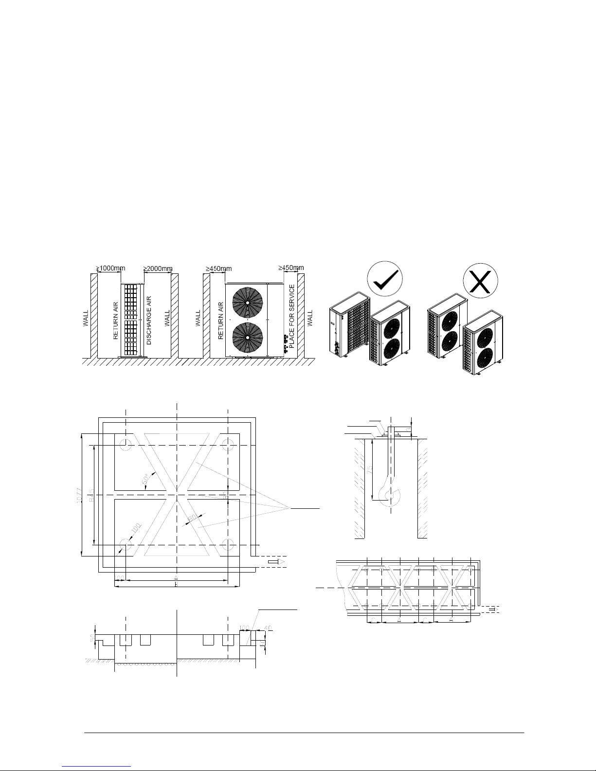
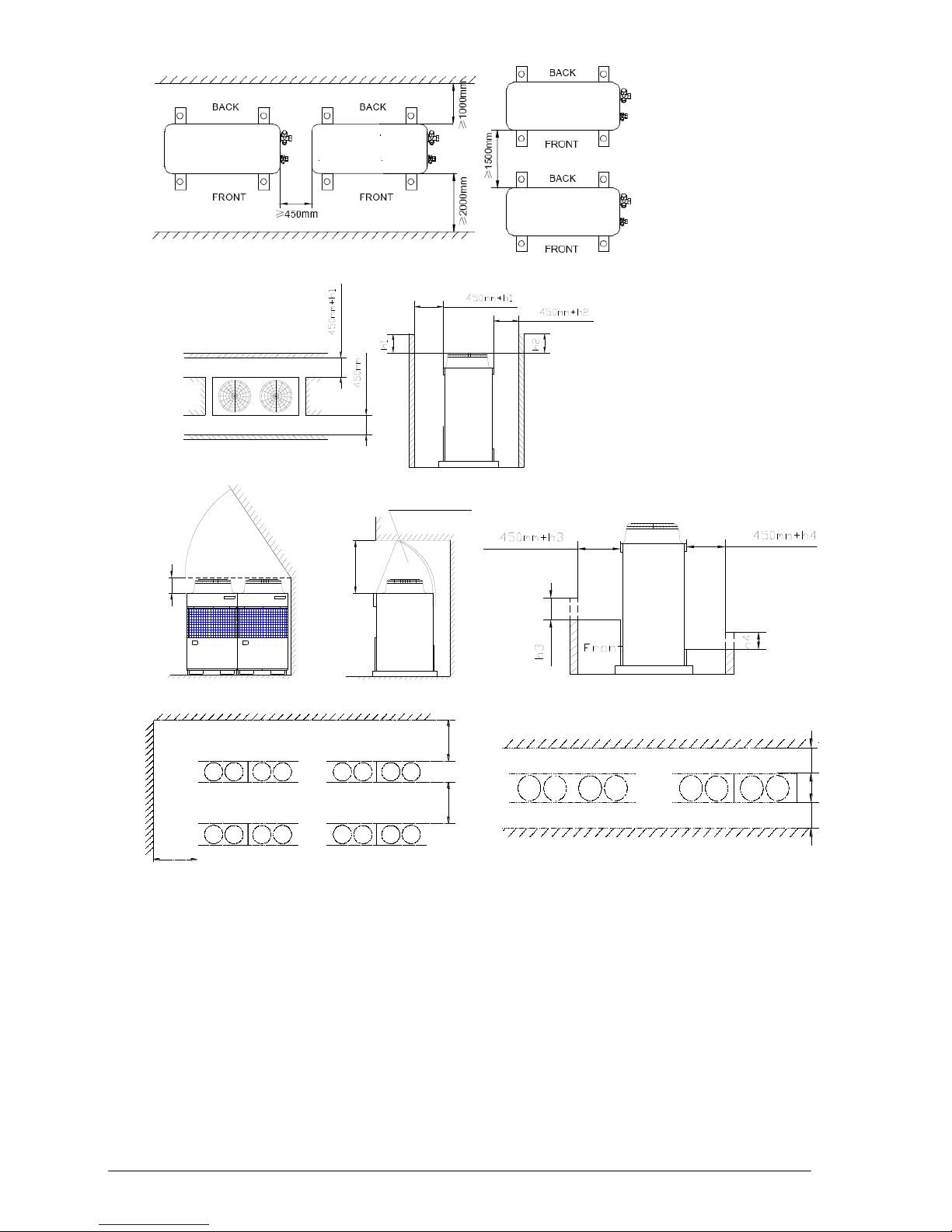
4.1 Location and space of installation
Avoid the discharge air from circulating back to air inlet.
Remove any barrier to improve the air ventilation.
Ensure enough space for maintenance.
Avoid installation of unit under corrosive environment.
Avoid installation of unit at places with flammable gas.
Follow the clearance when more than one outdoor unit is installed at the same location.
Constructing on the ground
x
Foundation nut installing
Many units concentrated installing
Constructing on the floor
AMDS200~240BR5
Mode
AMDS080~120BR5
AMDS140~180BR5
Drain ditch
Gradient is 1/40
x
Drain ditch
1900
2100
900
1200
A
1100
1400
B
Nut
Y Trough
Undercarriage
Spring washer
Bolt mode: JA
Dimension:M12
Quantity:4
MDS 30-70A(R)
5MDS 50-70B(R)
MDS 80-320B(R)
5MDS 80-500B(R)
Page 9
Installation Manual IM-MDS_(i) 5
≥
≥
≥
≥
≥
≥
≥ 45°
Front
Air Outlet Guide
≥
300mm
≥
1000mm
FRONT
BACK
FRONT
BACK
≥
450mm
≥
450mm
BACK
FRONT
FRONT
BACK BACK
FRONT
FRONT
BACK
≥600mm
≥
450mm
≥
900mm
MDS 30-70A(R)
5MDS 50-70B(R)
MDS 80-320B(R)
5MDS 80-500B(R)
Page 10

6 Installation Manual IM-MDS_(i)
4.2 Unit handling
Use 4 supporting points to move the units (refer to diagram).
Avoid unstable move to prevent unit drop off.
Do use special rope to tie the units for transportation.
Do not touch the fin to avoid injury.
Keep the plastic bag from reach of children.
4.3 Unit installation
Ensure the base is solid to support the unit.
Consider the location for drainage and piping installation.
Screw bolt to secure the 4 corners of the unit.
Use rubber absorber to prevent transfer of vibration.
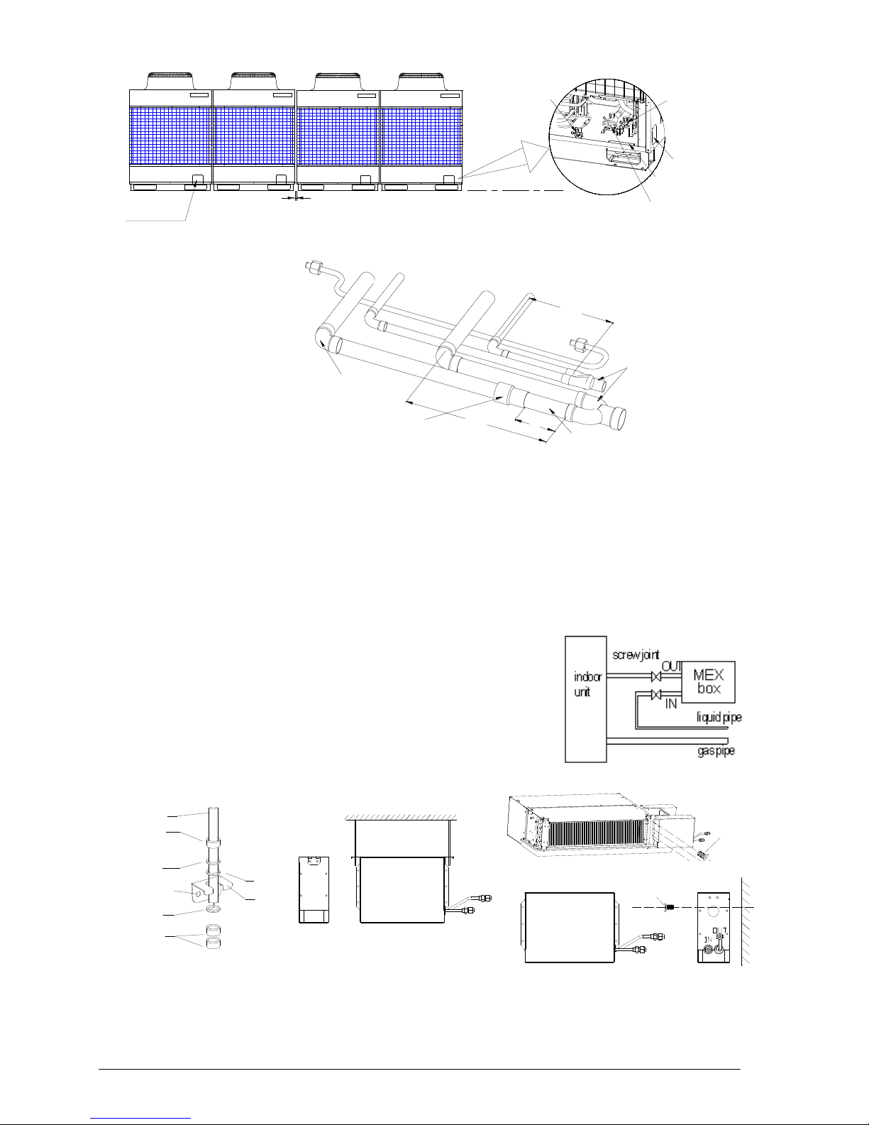
4.4 Installation of Master and Slave unit
Both master and slave unit must be positioned side by side and installed in the same level.
The distance between master and slave unit shall be more than 10mm.
Copper part accessories are packed with the outdoor units.
All piping should be insulated.
Gas and liquid piping should be connected paralleled to each other.
Balance piping must be installed. It should be connected through the hole of side panel, base panel or the
piping connection position with the other outdoor unit.
Balance piping shall be installed horizontally and it must be lower than the access valve of balance piping.
Balance piping shall not be touching any other parts.
Page 11
Installation Manual IM-MDS_(i) 7
5.0 Indoor Unit Installation
5.1 Location and space of installation
Ensure adequate air flow for the indoor unit and no obstacle around it.
Ensure enough space for maintenance and servicing.
Wall or ceiling shall be strong enough to support the indoor units.
Do not expose the unit under direct sunlight.
Do not install the indoor unit near to places with oil, steam or flammable gas.
Do not install the indoor unit at places with high frequency.
5.2 Installation of MEX Box
All indoor units need to connect to MEX Box.
It should be installed away from quiets such as bedroom.
Ensure the MEX box is vertical when installed. The distance between
MEX box and indoor unit could not exceed the maximum length limit
of the expansion valve cable. The cable needs to be plugged on the
control board of indoor unit.
MEX Box can be installed in any of the method shown below.
Remove the panel
C
For φ28.6mm gas pipe, directly
connect to Tri-joint; For φ34.9mm
gas pipe, add a reducer and a
transition pipe
Elbow
To units ball valve
Balance pipe
Liquid pipe
Gas pipe
A
Knock-out-hole
Piping connection position
To balance pipe
access valve
Tri-jiont
φ28.6mm a transiton pipe
(only for φ34.9mm gas pipe)
Connect pipe to
indoor units
D
A >10mm
B >200mm
C >500mm
D>100mm
B
To units ball valve
Ball valve (gas side)
Knock-out-hole
(for connecting balance pipe)
Access valve for
balance piping (φ9.52)
Knock-out-hole
Ball valve
(liquid side)
Master and slave must be
installed in the same level
steeve
nut
washer
hole for screw
washer
nut
washer
hook
SUSPENDING BY STEEVES
SCREW SETTING ON INDOOR UNIT
SCREW
SCREW SETTING ON WALL
SCREW
Page 12
8 Installation Manual IM-MDS_(i)
5.3 Installation of MCCD series indoor units
Use the hanger supplied with the unit.
Install the unit horizontally and ensure the slope for drainage is sufficient.
Ensure the distance between return air inlet and heat exchanger shall be at least 1m.
Do not open the valves, connector, copper cup and cover before installation.
Install the piping and drainage properly.
Use selected air distributor or diffuser to meet the design requirement.
Connect the return air inlet of indoor units with return air inlet on the ceiling.
Both air supply and return duct shall be insulated with aluminium foil.
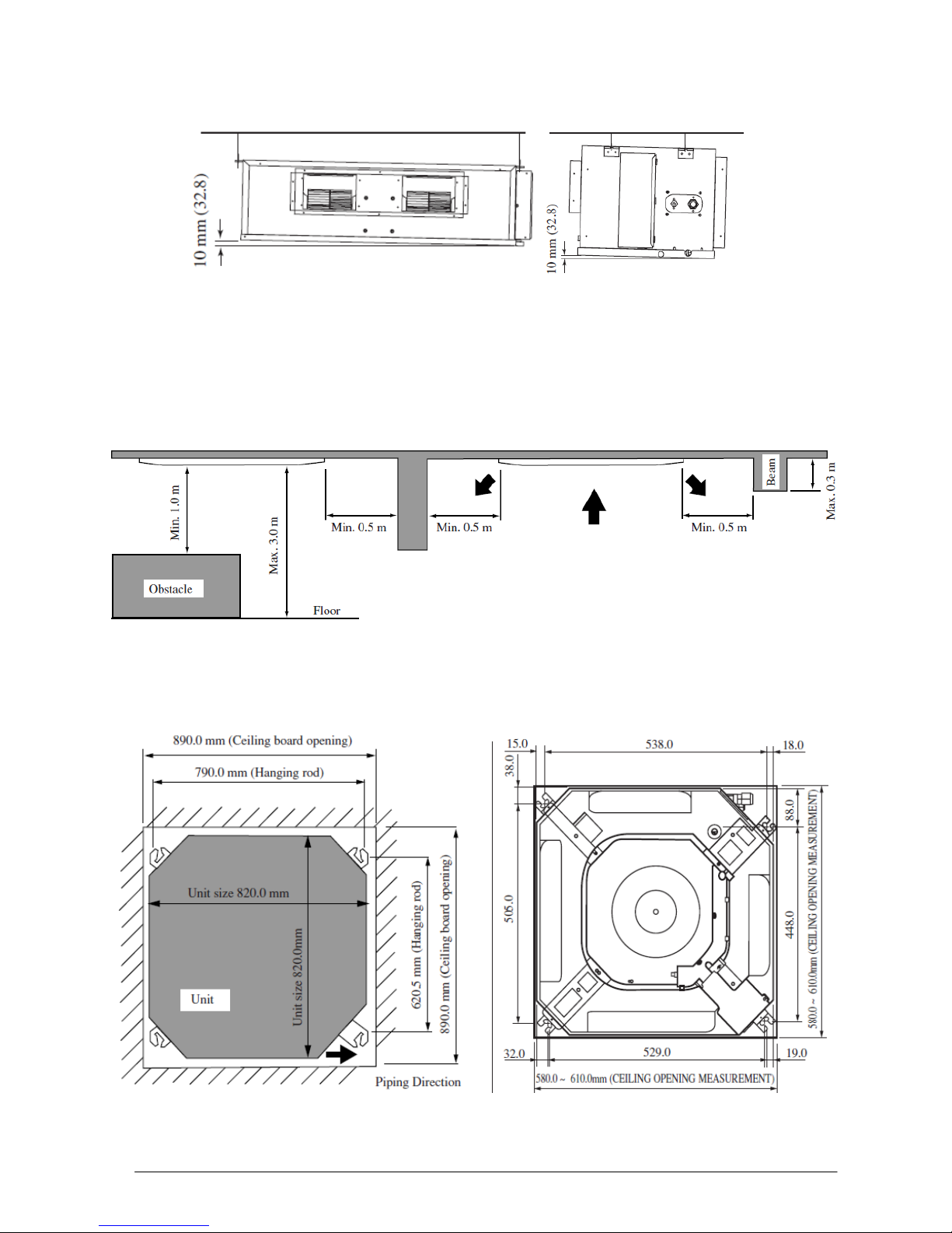
5.4 Installation of MCKD series indoor units
Ensure sufficient space for ventilation and no obstacle around the indoor unit.
The support shall carry weight 4 times larger than the indoor units to avoid unnecessary vibration and noise.
Keep the indoor units away from source of heat and vapour.
Use the installation template on the carton box to measure position for hanging rod. Drill the hole for the
angle nut on the ceiling and fix the hanging rod.
Confirm the pitch of the hanging rod as per figure below.
MCKD/M5CKD-A MCKD/M5CKD-C
Use nut and washer to fix the indoor units securely to prevent unit falling and vibration.
Page 13
Installation Manual IM-MDS_(i) 9
Adjust the unit height to 35mm (for MCKD-A) or 30mm (for MCKD-C) between the indoor unit bottom surface
and the ceiling surface.
Confirm with a level gauge that the unit is installed horizontally.
Open the ceiling board along the outer edge of the installation template.
Drain pipe must be in downward gradient for smooth drainage to
prevent reversed water flow.
When connecting the drain pipe, be careful not to exert extra force
on the drain connector at indoor unit.
The outer diameter of the drain connection at the flexible drain hose
is 20mm.
Ensure to apply insulation (polyethylene foam with thickness more
than 8mm) on the drain piping to avoid the condensed water dripping
inside the room.
Connect the main drain pipe to the flexible drain hose.
Feed water from flexible drain hose to check the piping for leakage.
When the test is completed, connect the flexible drain hose to the drain
connector on the indoor unit.
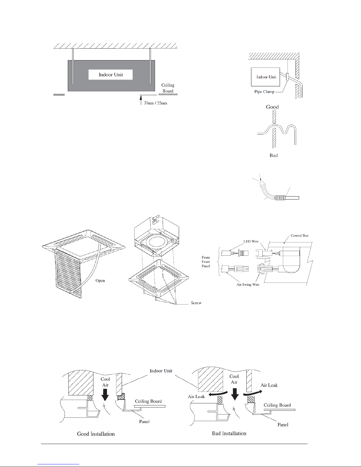
The front panel can only be fitted in one direction, following the piping direction. (Follow piping arrow sticker
on front panel).
Be sure to remove the installation template before installing the front panel.
Open the air intake grille by pulling back the catchers and removing it together with filter from panel.
Install the front frame panel onto the indoor unit by 4 screws and tighten it completely to prevent cool air
leakage.
Connect the LED wire and air swing wire to the indoor unit.
Install the front panel firmly to prevent cool air leakage which will cause condensation and water dripping.
drain pipe
drain & leakage test
fill water
flexible pipe
Drain pipe installation
Front panel installation
Wire connection between unit and panel
Drainage leak test
Page 14
10 Installation Manual IM-MDS_(i)
Install the air intake grille together with the air filter to the front panel.
The grille can be fit in any direction, when selecting direction, the ceiling
design and grille operability should be considered.
If the unit comes with ionizer filter (optional item), make sure to fix the
ionizer filter to the air filter before installing the air intake grille.
Fix the ionizer filter to the air filter with the black side on top and white
side at bottom. Carefully clip on the ionizer filter frame.
Note that water pump is installed in this type of indoor unit.
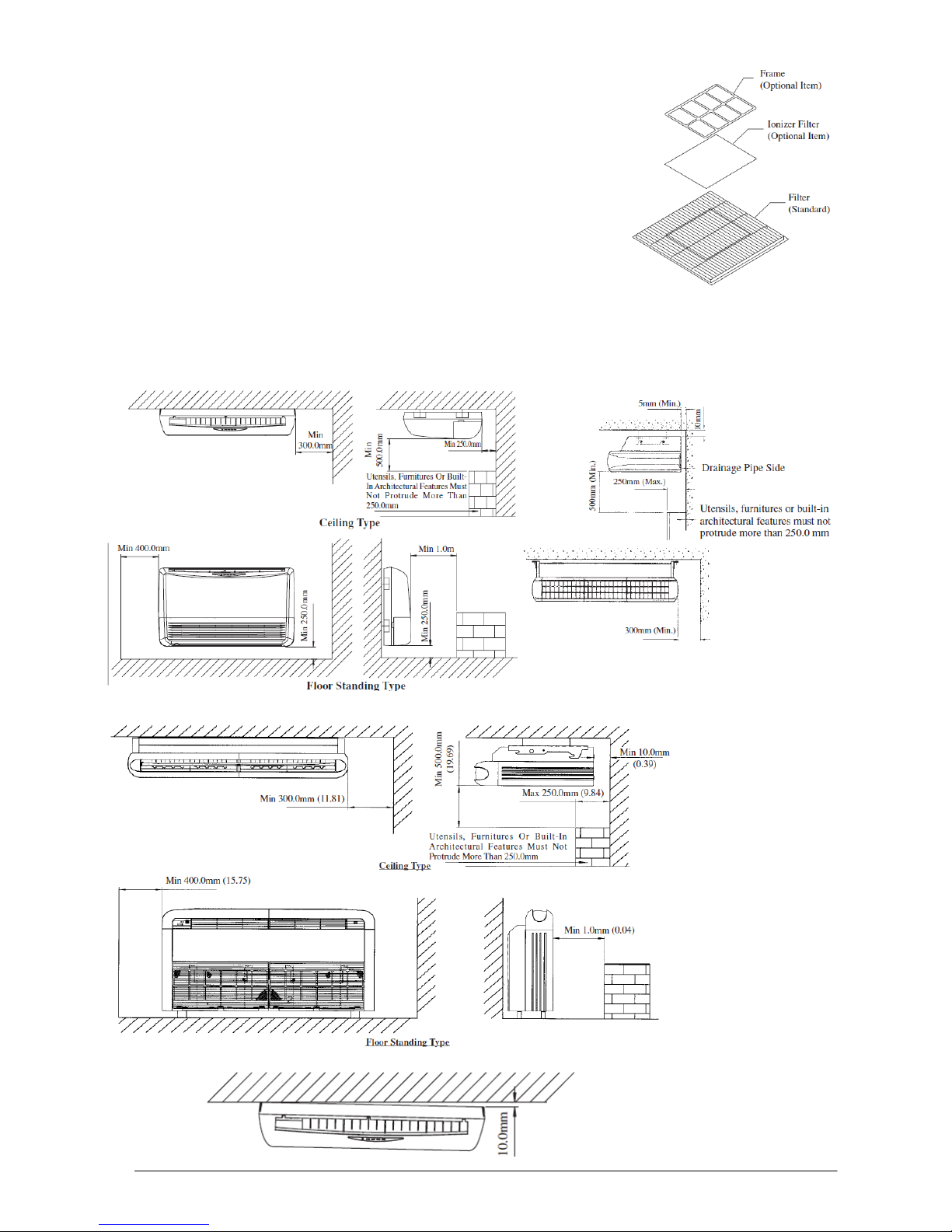
5.5 Installation of MCMD series indoor units
Ensure sufficient space for ventilation and no obstacle around the indoor unit.
Install the unit horizontally and ensure the slope for drainage is sufficient.
Note that MCMD/M5CMD62C is unable to be installed in floor standing position.
MCMD/M5CMD-E Series
MCMD/M5CMD-C Series
MCMD/M5CMD-D Series
Slope for drainage
Page 15

Installation Manual IM-MDS_(i) 11
Ensure the overhead supports are strong enough to hold the weight of the unit.
Position the hanger rods and check for its alignment with the unit. Also check that the hangers are secured
and the base of the indoor unit is levelled in both horizontal directions.
Provide clearance for easy serviceability and optimal air flow.
The unit must be installed a large distance away from the door to avoid direct sunlight.
The location of indoor unit should be suitable for piping and drainage installation.
The indoor unit must be installed such that there is no short circuit of cool discharge air with the warm return
air.
Air return grill
Frame
Suspending
panel
Panel side
Installation of MCMD/M5CMD-C/D Series
Installation of MCMD/M5CMD-E Series
Ceiling Type Installation
Page 16

12 Installation Manual IM-MDS_(i)
5.6 Installation of MWMD series indoor units
Ensure sufficient space for ventilation and no obstacle around the indoor unit.
The indoor unit must be installed in such a way so as to prevent short circuit of cool discharged air with the
hot return air. Please follow the installation clearance shown below.
Do not expose the indoor unit to direct sunlight and away from doors and windows.
Consider the location of piping and drainage when selecting the installation space.
The refrigerant piping can be routed to the unit in a number of ways by using the cut-out holes on the casing
of the unit.
Floor Type Installation
Page 17

Installation Manual IM-MDS_(i) 13
Ensure that the wall is strong enough to withstand the weight of the unit. Otherwise, it is necessary to
reinforce the wall with plates, beams or pillars.
Use the level gauge for horizontal mounting and fix it with 4 suitable screws.
In case the rear piping draws out, drill a hole 65mm in diameter with a cone drill, slightly lower on the outside
wall.
The indoor drain pipe must be in a downward gradient for smooth drainage. Avoid situations that are likely to
cause water to leak.
Hook the indoor unit onto the upper portion of the installation plate (engage the two hooks at the rear top of
the indoor unit with the upper edge of the installation plate).
Ensure that the hooks are properly seated on the installation plate by moving it to the left and right.
6.0 Piping Installation
MDS system is a “one outdoor unit coupled with many indoor units” system. For piping connection, there are gas
pipe and liquid pipe connection with flare joint.
6.1 Precautions for piping installation
Check and ensure the thickness, diameter and cleanliness of the copper tube is within specification.
It is not allowed to vacuum the system with refrigerant.
Do not use any detergent to clean the refrigerant piping.
Seal the outlet of the copper tube to avoid dust, dirt or water from entering.
Do not install the copper pipe during rainy day.
Avoid bending and turning of piping. Special tools must be used to bend the piping.
Use the right equipment for brazing the copper tube.
All copper tube must be insulated to ensure heat exchange efficiency and to avoid water from condensing.
The outdoor ball valve should remain closed until the completion of leakage test and vacuum process.
Ensure the unit is properly charged with the correct amount of refrigerant.
Page 18

14 Installation Manual IM-MDS_(i)
6.2 Refrigerant piping system
The below 3 piping structure designs are recommended.
It is not allowed to connect any refnet after the distributor.
balance pipe
Tee joint
Bifurcation
Indoor unit
Distributor
Indoor unit
Balance pipe
Tee joint
Distributor
Bifucation
Balance pipe
Tee joint
Indoor unit
Distributor
Distributor
balance pipe
Tee joint
Indoor uint
Wrong connection
Bifurcation
Wrong connection
Page 19
Installation Manual IM-MDS_(i) 15
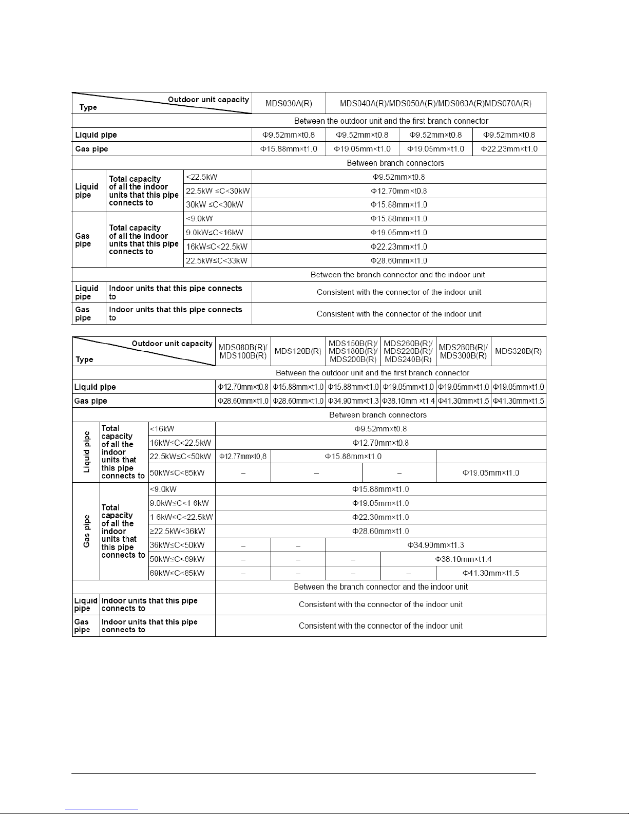
6.3 Piping size, refnet and distributor selection
Select the piping, refnet and distributor base on the tables and diagrams below.
Refrigerant piping
Page 20

16 Installation Manual IM-MDS_(i)
R410A Piping Materials/Radial Thickness
Type
TP2M
TP2Y2
Diameter (mm)
6.4
9.5
12.7
15.9
19.1
22.2
25.4
28.6
31.8
34.9
38.1
41.3
Diameter (inch)
1/4
3/8
1/2
5/8
3/4
7/8 1 1-1/8
1-1/4
1-3/8
1-1/2
1-5/8
Minimum
Thickness
(mm)
0.8
0.8
0.8
1.0
1.0
1.0
1.0
1.0
1.1
1.3
1.4
1.5
The minimum thickness of the pipe in the chart is based on the PRC Standard Specification for Drawn Tube
of Copper and Copper Alloys (GB/T1527-1997), TP2M and TP2Y2 are the marks of the material brand and
state. Using this table as reference, choose the pipe that meets the local standards and the maximum
operation pressure reaches 4.15MPa.
If the unit is used in the environment which is eroded seriously, it should be thickened by 0.2mm.
The table shows the minimum thickness. If the pipe needs to be bent or drawn, please add the extra
thickness appropriately.
Page 21

Installation Manual IM-MDS_(i) 17
Refnet
Page 22

18 Installation Manual IM-MDS_(i)
Horizontal
Vertical
installation
<30°
Direction A
view
Horizontal
installation
Direction A
Outdoor
Oil trap
(every 6~8m fall of the
gas pipe set a oil trap)
Indoor
Installation of refnet and distributor should be within the allowable tolerance as shown in diagrams below.
Installation of the system should within the piping length limitation as shown below.
MDS
5MDS
Length (m)
30-50
60-70
80-320
50
60-70
80-500
Piping
Total equivalent length
100
150
350
100
150
500
Maximum length of
longest branch
Actual piping length
50
70
125
50
70
150
Equivalent length
60
80
150
60
80
175
Maximum equivalent length from first
branch to furthest unit
25
30
40
25
30
65
Height
Between further
indoor and outdoor
outdoor above
20
30
50
20
30
50
indoor above
20
30
40
20
30
40
Maximum height between indoor unit
15
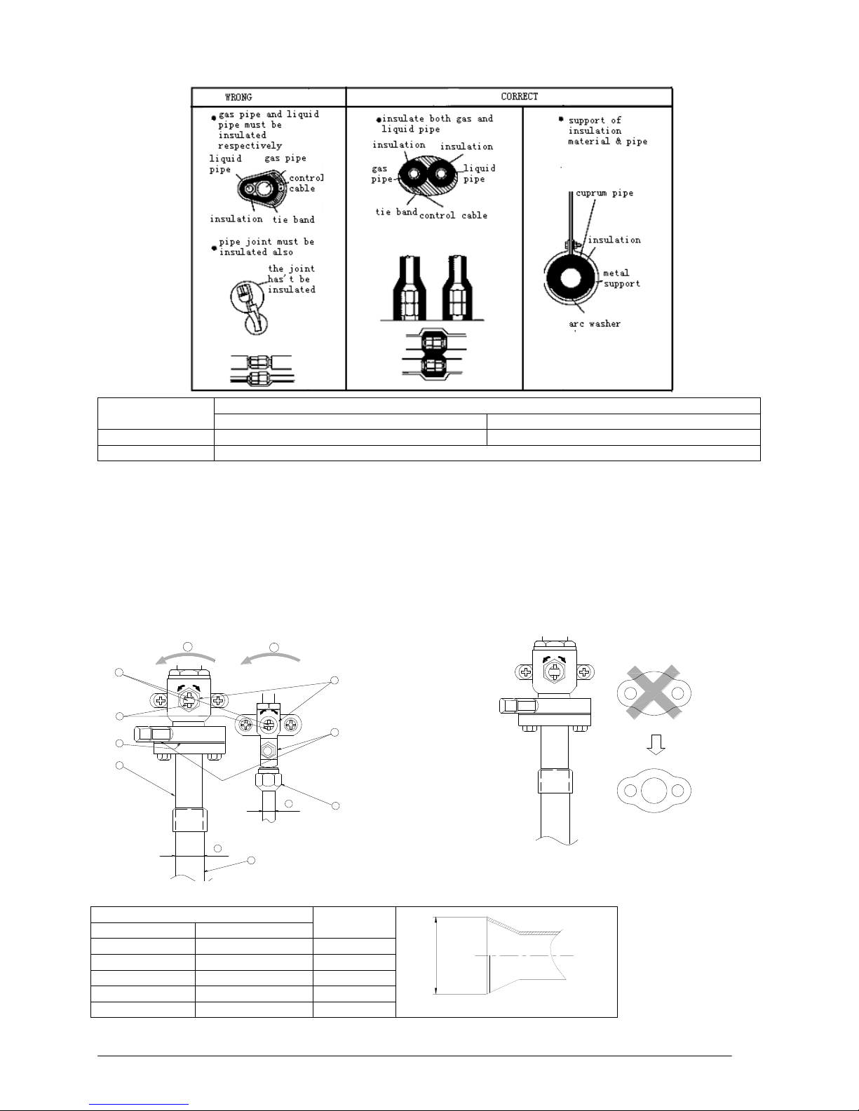
6.4 Insulation of refrigerant piping
All refrigerant piping must be insulated to ensure heat exchange efficiency and prevent water condensing.
Specification of insulation material is as below.
Insulation Material
Fiberglass+Steel
Adhering material+Chloroethylene foam+adhering strip
Layer
Indoor
Chloroethylene insulation strip
Bare floor
Water proof flax+Bronze Pitch
outdoor
Water proof flax+galvanized panel+painting
Maximum height
between indoor units
Height between further
indoor and outdoor
Maximum length of
longest branch
Page 23
Installation Manual IM-MDS_(i) 19
so
Close-packed
packing
Hollow
packing
ball valve
(gas side)
A Valve stem
B Stopper pin
C Packing(accessory)
D Connecting pipe(accessory)
E Open
F Cap, copper packing
G Service port
H Flare nut
I Liquid pipe diameter
J Gas pipe diameter
K Field piping
ball valve
(liquid side)
o s
o s
A
B
C
D
J
K
H
G
I
F
E
E
diameter
The proper steps to insulate the refrigerant piping are shown below.
Pipe Specification
Diameter 6.35 - 25.4mm
Diameter 28.58 - 41.3mm
Thickness
Min 10mm
Min 12mm
Heat resistance
Min100℃
6.5 Ball valve installation and operation
Operate the gas side ball valve
o Uninstall the flange connector: remove the flange connector from the piping
o Stick the seal material to cover the inlet of the ball valve flange to avoid the dirt entry
o Change the hollow seal pad
o Fix the flange connector and hollow seal pad and fixed ball valve of gas side with screw bolt.
Liquid side ball valve connecting: expand the copper tube outlet and connect the ball valve connector
Vacuum and charge in refrigerant, ensure to open the valve completely
Calculate the additional refrigerant and charge into units accordingly
Check the looseness to avoid leakage of refrigerant
Copper tube expanded connector dimension. (unit: mm)
External Diameter
Diameter
mm
inch
Ф6.35
1/4”
9.0
Ф9.52
3/8”
13.0
Ф12.7
1/2”
16.2
Ф15.88
5/8”
19.4
Ф19.05
3/4”
23.3
Page 24

20 Installation Manual IM-MDS_(i)
diameter
Matching screw specification. (unit: mm)
Diameter
Diameter
mm
inch
Ф6.35
1/4”
17.0
Ф9.52
3/8”
22.0
Ф12.7
1/2”
24.0
Ф15.88
5/8”
27.0
Ф19.05
3/4”
36.0
When connecting the liquid piping and liquid ball valve, use wrench to fix tightly and ensure they are in the
same axial.
Outside diameter(mm)
Moment(N.m)
angle (˚ ) Ф6.35
14~18
60~90
Ф9.52
35~42
60~90
Ф12.7
50~57.5
30~60
Ф15.88
75~80
30~60
Ф19.05
100~140
20~35
7.0 Wiring Connection
7.1 General wiring precautions
Power of indoor and outdoor units must be supplied simultaneously.
Cable for power and communication should be designed in parallel and maintain a distance of more than
20cm between them.
Communication cable should be screened to avoid interference of strong signal. Total wire length should be
less than 1000m.
Signal wire has two poles of A and B the same pole must be connected in one connection (A to A, B to B).
Screened layer of signal wires should be earthed.
Outdoor units use either 3 phase or single phase supply (depends on model) while indoor units use only
single phase power cable.
Wiring diagram can be obtained within the units.
7.2 Wire specification
For communication wire, please use below standard.
A: conducting wiring (copper, intersection surface is more than 0.5mm2 or 20AWG)
B: Insulation material
C: Screen layer (efficiency shall be higher than 95%)
D: outside layer protector (PVC)
For wiring cable, please refer to UL2547 and UL2791 standard
Wiring cable
Page 25

Installation Manual IM-MDS_(i) 21
7.3 Electrical wiring connection
For single unit connection.
For master and slave units connection.
Fuse
Switch
Two-core cable
(power circuit)
Two-core cable
(power circuit)
Switch
Fuse
Indoor unit
Fuse
Switch
L1
Switch
Fuse
L2L1
L3
N
Power
Outdoor unit
N
L2
L3
Indoor unit
Switch
Fuse
Fuse
Switch
Power
L1
L2
Fuse
Switch
L1
L2
L3L2N
Fuse
Switch
L1
L3
N
L3
N
Two-core cable
(power circuit)
Switch
Fuse
Outdoor unit
Master
Slave
Two-core cable
(power circuit)
Indoor unit
Master
Outdoor unit
Two-core cable
(power circuit)
Two-core cable
(power circuit)
Fuse
Switch
L1
N
Switch
Fuse
L1
N
Power
L3
L1 L2
N
Fuse
Switch
L2
L1
L3
N
Switch
Fuse
L1
N
Slave
Separate Connection
Serial Connection
Page 26

22 Installation Manual IM-MDS_(i)
Indoor unit 1
To network or central
control (optional)
Communication cable
Screen
layer
Detail for
Terminal
A
pc
Outdoor unit
Control box
Main PCB
Connection
port
B
pc
A
pc
A
in
B
in
B
pc
B
in
A
in
Control box
A B
PCB
Control box
Indoor unit 2
B
Communication cable
Control box
A
PCB
Communication cable
JP1 of last unit on
main bus should be on
Indoor unit i
A B
PCB
JP1
A
B
A
B
A
B
Connection port
com1
com2
com2
com1
Connection port
Connection port
com2
com1
Master unit
Outdoor unit
To network or central
control (optional)
A
in
B
in
B
pc
A
pc
Main PCB
Connection
port
Screen
layer
Communication cable
Connection
port
Slave unit
Main PCB
A
in
B
pc
A
pc
B
in
Indoor unit 2
Communication cable
Indoor unit 1
Control box
PCB
Connection port
A B
Control box
PCB
A B
JP1 of last unit on
main bus should be on
Indoor unit i
B
Communication cable
Control box
A
PCB
JP1
A
B
A
B
A
B
com2
Connection port
Connection port
com1
com2
com2
com1
com1
PCB
BA
A B
PCB
Connect A with B, wrong
A
B
A
B
com2
Connection port
Connection port
com2
com1
7.4 Communication wiring connection
For single unit connection.
For master and slave units connection.
Example of wrong connection.
not bus structrue,connection cable
should be layed as bus structure
Bpc
AinApc
Bin
Outdoor unit
Control box
Main PCB
Connection
port
Screen
layer
BA
A B
PCB
Control box
Indoor unit 1
Indoor unit 2
Communication cable
Communication cable
PCB
Control box
A
B
A
B
Connection port
Connection port
com1
com2
com2
com1
B
pc
A
in
A
pc
B
in
Screen layer must be
grounded with outdoor unit
Control box
Connection
port
Main PCB
PCB
A
B
Neglect to
connect
A
B
Connection port
com1
com2
Page 27

Installation Manual IM-MDS_(i) 23
7.5 Dip switch setting
Indoor unit address setting for all indoor (dip switch SW2).
S2.1 S2.2 S2.3 S2.4 S2.5 S2.6 Indoor Address S2.1 S2.2 S2.3 S2.4 S2.5 S2.6 Indoor Address
0 0 0 0 0 0 0 0 1 1 0 0 0 24
0 0 0 0 0 1 1 0 1 1 0 0 1 25
0 0 0 0 1 0 2 0 1 1 0 1 0 26
0 0 0 0 1 1 3 0 1 1 0 1 1 27
0 0 0 1 0 0 4 0 1 1 1 0 0 28
0 0 0 1 0 1 5 0 1 1 1 0 1 29
0 0 0 1 1 0 6 0 1 1 1 1 0 30
0 0 0 1 1 1 7 0 1 1 1 1 1 31
0 0 1 0 0 0 8 1 0 0 0 0 0 32
0 0 1 0 0 1 9 1 0 0 0 0 1 33
0 0 1 0 1 0 10 1 0 0 0 1 0 34
0 0 1 0 1 1 11 1 0 0 0 1 1 35
0 0 1 1 0 0 12 1 0 0 1 0 0 36
0 0 1 1 0 1 13 1 0 0 1 0 1 37
0 0 1 1 1 0 14 1 0 0 1 1 0 38
0 0 1 1 1 1 15 1 0 0 1 1 1 39
0 1 0 0 0 0 16 1 0 1 0 0 0 40
0 1 0 0 0 1 17 1 0 1 0 0 1 41
0 1 0 0 1 0 18 1 0 1 0 1 0 42
0 1 0 0 1 1 19 1 0 1 0 1 1 43
0 1 0 1 0 0 20 1 0 1 1 0 0 44
0 1 0 1 0 1 21 1 0 1 1 0 1 45
0 1 0 1 1 0 22 1 0 1 1 1 0 46
0 1 0 1 1 1 23 1 0 1 1 1 1 47
Indoor unit capacity setting for all indoor (dip switch SW3).
Outdoor unit address setting for MDS30-70A(R) and 5MDS50-70B(R) (dip switch J2).
J2.1 J2.2 J2.3 J2.4 J2.5 Outdoor Address
0 0 0 0 0 0
1 0 0 0 0 1
0 1 0 0 0 2
1 1 0 0 0 3
0 0 1 0 0 4
1 0 1 0 0 5
0 1 1 0 0 6
1 1 1 0 0 7
0 0 0 1 0 8
1 0 0 1 0 9
0 1 0 1 0 10
1 1 0 1 0 11
0 0 1 1 0 12
1 0 1 1 0 13
0 1 1 1 0 14
1 1 1 1 0 15
S3.1 S3.2 S3.3 S3.4 S3.5 Capacity (kW) Model Name
0 0 0 1 0 2.5 09
1 0 1 1 0 2.8 10
0 0 1 0 0 3.6 15
0 1 0 0 0 5.6 20
0 1 0 1 0 6.5 25
1 1 0 1 0 8.0 28
1 1 1 0 0 9.0 30
0 1 1 1 0 10.0 38
1 1 1 1 0 11.2 40
1 0 0 1 0 14.0 50
0 1 0 1 1 16.4 60/62
0 0 0 0 1 22.4 80
0 0 0 1 1 28.0 100
S3.6 S3.7 S3.8 Indoor Type
0 0 0 Ceiling Concealed
0 0 1 Ceiling Cassette
0 1 0 Ceiling Convertible
0 1 1 Wall Mounted
1 0 0 Ducted Blower
Page 28

24 Installation Manual IM-MDS_(i)
Outdoor unit address setting for MDS/5MDS80-500B(R) (dip switch S2).
S2.4 S2.5 S2.6 S2.7 S2.8 Outdoor Address S2.4 S2.5 S2.6 S2.7 S2.8 Outdoor Address
0 0 0 0 0 0 1 0 0 0 0 16
0 0 0 0 1 1 1 0 0 0 1 17
0 0 0 1 0 2 1 0 0 1 0 18
0 0 0 1 1 3 1 0 0 1 1 19
0 0 1 0 0 4 1 0 1 0 0 20
0 0 1 0 1 5 1 0 1 0 1 21
0 0 1 1 0 6 1 0 1 1 0 22
0 0 1 1 1 7 1 0 1 1 1 23
0 1 0 0 0 8 1 1 0 0 0 24
0 1 0 0 1 9 1 1 0 0 1 25
0 1 0 1 0 10 1 1 0 1 0 26
0 1 0 1 1 11 1 1 0 1 1 27
0 1 1 0 0 12 1 1 1 0 0 28
0 1 1 0 1 13 1 1 1 0 1 29
0 1 1 1 0 14 1 1 1 1 0 30
0 1 1 1 1 15 1 1 1 1 1 31
Outdoor unit indoor quantity setting for MDS/5MDS80-500B(R) (dip switch S1).
S1.3 S1.4 S1.5 S1.6 S1.7 S1.8 Indoor Quantity S1.3 S1.4 S1.5 S1.6 S1.7 S1.8 Indoor Quantity
0 0 0 0 0 0 1 0 1 1 0 0 0 25
0 0 0 0 0 1 2 0 1 1 0 0 1 26
0 0 0 0 1 0 3 0 1 1 0 1 0 27
0 0 0 0 1 1 4 0 1 1 0 1 1 28
0 0 0 1 0 0 5 0 1 1 1 0 0 29
0 0 0 1 0 1 6 0 1 1 1 0 1 30
0 0 0 1 1 0 7 0 1 1 1 1 0 31
0 0 0 1 1 1 8 0 1 1 1 1 1 32
0 0 1 0 0 0 9 1 0 0 0 0 0 33
0 0 1 0 0 1 10 1 0 0 0 0 1 34
0 0 1 0 1 0 11 1 0 0 0 1 0 35
0 0 1 0 1 1 12 1 0 0 0 1 1 36
0 0 1 1 0 0 13 1 0 0 1 0 0 37
0 0 1 1 0 1 14 1 0 0 1 0 1 38
0 0 1 1 1 0 15 1 0 0 1 1 0 39
0 0 1 1 1 1 16 1 0 0 1 1 1 40
0 1 0 0 0 0 17 1 0 1 0 0 0 41
0 1 0 0 0 1 18 1 0 1 0 0 1 42
0 1 0 0 1 0 19 1 0 1 0 1 0 43
0 1 0 0 1 1 20 1 0 1 0 1 1 44
0 1 0 1 0 0 21 1 0 1 1 0 0 45
0 1 0 1 0 1 22 1 0 1 1 0 1 46
0 1 0 1 1 0 23 1 0 1 1 1 0 47
0 1 0 1 1 1 24 1 0 1 1 1 1 48
For master and slave unit, set the master unit’s S2.1 as 1, and set the slave unit’s S2.1 as 0.
Address cannot be duplicated and must be continuous without skipping any address in between.
The address of first unit must be 0. Address and indoor quantity code of the slave unit need not to be set.
Start up the unit after the address setting has been completed.
1 stands for On while 0 stands for Off.
7.6 Auto restart setting
To allow indoor unit to auto restart once power resume from failure, apply the setting as below.
For wireless controller, to enable auto restart, the steps are as follow:
1. Press the indoor PCB emergency ON/OFF button for 5 seconds to go into setting mode. When the unit
are in setting mode, all the LED of the indoor will be light up.
2. Use the wireless handset, select “Fan” mode.
3. Select “High Fan” speed.
4. Press the “ON/OFF” button on the wireless handset to complete the setting. Once the setting is
complete, all the indoor LED will be turned off and the unit will remain in standby mode.
To disable auto restart, the steps are as follow:
1. Press the indoor PCB emergency ON/OFF button for 5 seconds to go into setting mode. When the unit
are in setting mode, all the LED of the indoor will be light up
2. Use the wireless handset, select “Fan” mode.
3. Select “Medium Fan” speed
4. Press the “ON/OFF” button on the wireless handset to complete the setting. Once the setting is
complete, all the indoor LED will be turned off and the unit will remain in standby mode.
For wired controller, turn On dip switch 2 at the back of the controller to enable auto restart function. To
disable it, turn Off dip switch 2.
Page 29

Installation Manual IM-MDS_(i) 25
LEAKAGE TEST SKETCH
to indoor unit
to indoor unit
nitrogen
LO
outdoor
unit
ball valve
ball valve
liquid pipe
gas pipe
HI
service port
pressure gauge
8.0 Air Leakage Test, Vacuum and Refrigerant Charge
8.1 Air leakage test
To conduct air leakage test, ensure the ball valve is off.
Refer to the procedure below to avoid polluting the lubricating
oil during the leakage test.
Air leakage testing procedure
Remark
Charging Nitrogen gas
Nitrogen gas (For R410A units: 4.15MPa, R22 units: 2.94MPa),
wait for 24 hours. If the pressure is not drop, the units pass the
air tightness testing; if pressure decrease, use soap water to
detect the leakage point.
After charging the nitrogen gas, use soap water on the part of
brazing, flange and connection position to see if there is any
bubble occurred.
After air leakage testing, wipe off the bubbling agent.
Do not use oxygen and other flammable
air to increase the pressure to avoid
explosion
8.2 Vacuum
Ensure the ball valve is off before conducting vacuum.
Vacuum pressure is 650Pa and the time of vacuum is
24 hours.
Do not use refrigerant to vacuum.
8.3 Charging the refrigerant
Charge in additional refrigerant based on the piping length connection.
Additional charge required can be obtained from selection report or calculated manually with the steps as
shown below.
Additional charge amount:
= ∑ Li* Gi
= (Piping Length for 15.88mm X Additional Charge Amount)
+ (Piping Length for 12.7mm X Additional Charge Amount)
+ (Piping Length for 9.52mm X Additional Charge Amount)
+ (Piping Length for 6.35mm X Additional Charge Amount)
Caution that the additional charge amount of different pipe diameter varies base on type of refrigerant.
Pipe Diamater (mm) 6.35 9.52 12.70 15.88 19.05
R22 Additional Charge (g/m) 50 80 120 180 290
Pipe Diamater (mm) 6.35 9.52 12.70 15.88 19.05
R41A additional Charge (g/m) 45 70 120 180 260
Before charging, open the all ball valve.
vacuum
pump
check valve
service port
ball valve
liquid pipe
gas pipe
ball valve
outdoor
unit
compound
pressure gauge
HI
LO
to indoor unit
to indoor unit
VACUUM SKETCH
Page 30

26 Installation Manual IM-MDS_(i)
REFRIGERANT CHARGING SKETCH
weighbridge
refrigerant
tank
compound
pressure gauge
HI
LO
to indoor unit
to indoor unit
service port
ball valve
liquid pipe
gas pipe
ball valve
outdoor
unit
refrigerant
tank
weighbridge
LO
HI
compound
pressure gauge
outdoor
unit
ball valve
gas pipe
liquid pipe
ball valve
service port
to indoor unit
to indoor unit
When charging R410A with cylinder which is without the siphon pipe, turn the cylinder upside down when
charging to ensure only liquid refrigerant is charged into the system.
9.0 Commissioning
9.1 Checking list before commissioning
Ampere of indoor & outdoor units is normal and under protection value?
Power supply for indoor and outdoor units is normal?
Dip switch address setting up for indoor units are ok?
Indoor unit is power on?
Communication wiring is ok?
Refnet is well installed?
Condensing water drainage system is ok?
Earthing is ok?
Insulation testing (10Mega Ω)
Power supply check (220-240V/380-415V)
System has been vacuumed and charged with additional refrigerant?
How many indoor units are controlled by outdoor unit controller?
Outdoor unit ball valve is opened?
9.2 Commissioning record table
Before commissioning, power on the system 24 hours in advance to preheat the crankcase heater.
No.
Suction
pressure(bar)
Discharge
pressure
(bar)
Voltage
(V)
Ampere
(A)
Suction
temperature
(℃ )
Ambient
Temp.(
℃ )
Checking person
/ Time
1 2 3 4 5 6
9.3 Common problems during commissioning
Symptoms
Wiring controller
Possible reason
No heating or cooling
Cannot select cooling or heating
When one indoors units in heating, all
indoors in heating mode
Fan stop when heating
Defrost
Fan stop running when defrosting
Pump keep running
No indication
Pump keep running to drain the water
The cylinder had Syphon pipe
Syphon pipe
Page 31

Installation Manual IM-MDS_(i) 27
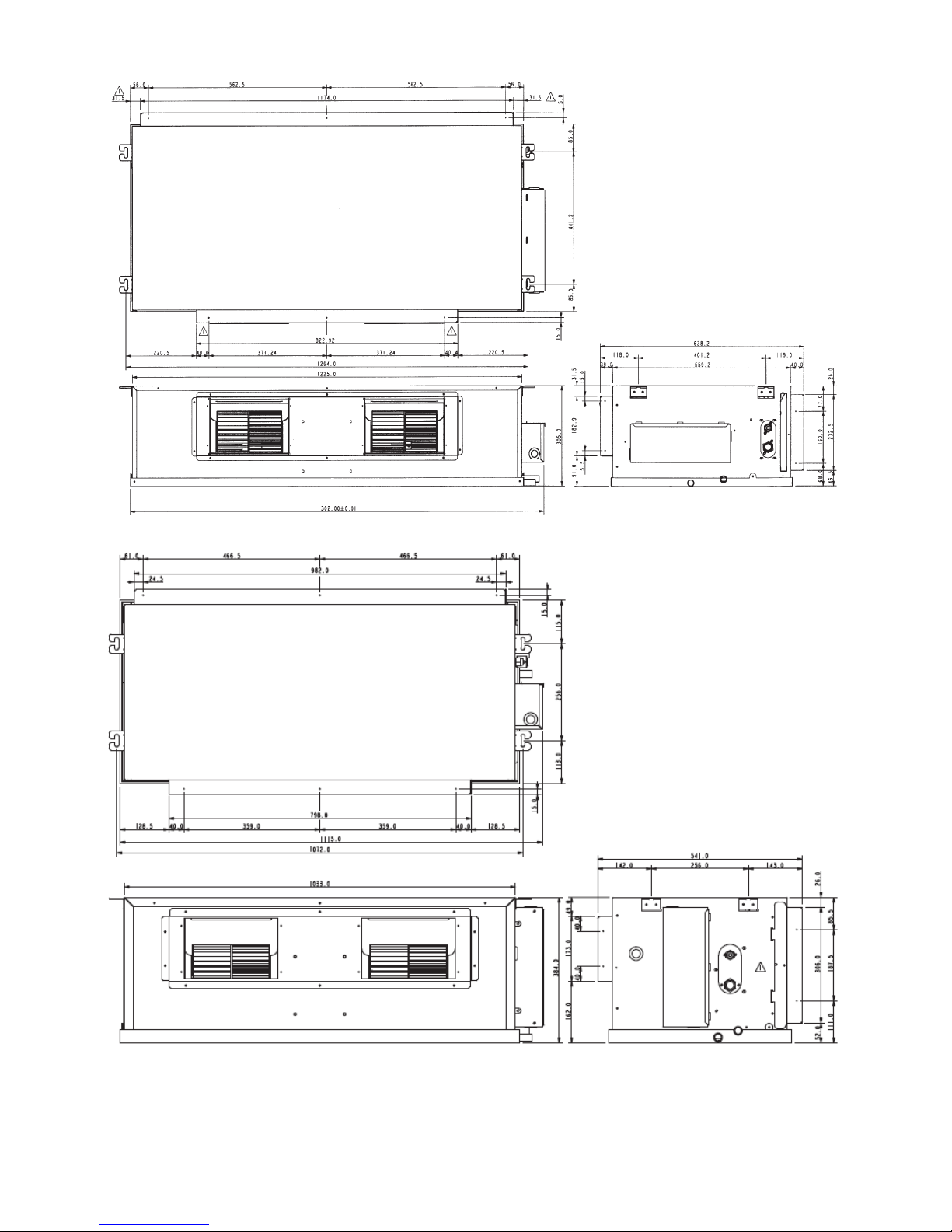
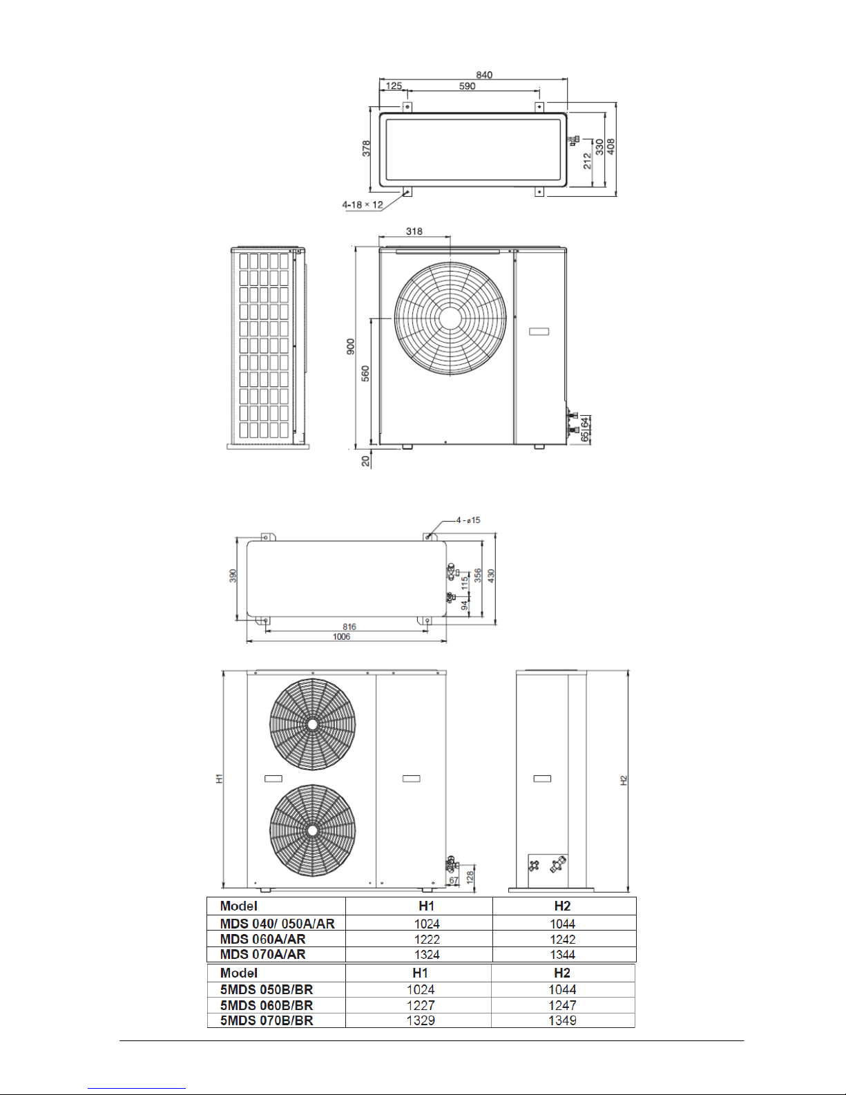
10.0 Unit Outlines and Dimensions
MWMD/M5WMD 009/010/015G
MWMD/M5WMD 020/025G
Page 32

28 Installation Manual IM-MDS_(i)
MCKD/M5CKD 020/025/030/040/050A
MCKD/M5CKD 010/015/020C
MCMD 020/025/028E
M5CMD 015/020/025/028E
Page 33

Installation Manual IM-MDS_(i) 29
MCMD/M5CMD 040/050D
MCMD/M5CMD 062C
Page 34

30 Installation Manual IM-MDS_(i)
MCCD/M5CCD 010C
MCCD/M5CCD 015/020/025C
Page 35

Installation Manual IM-MDS_(i) 31
MCCD/M5CCD 028C
MCCD/M5CCD 030C
Page 36
32 Installation Manual IM-MDS_(i)
MCCD/M5CCD 038C
MCCD/M5CCD 040C
Page 37

Installation Manual IM-MDS_(i) 33
MCCD/M5CCD 050C
MCCD/M5CCD 060C
Page 38
34 Installation Manual IM-MDS_(i)
MDS 030A(R)
MDS 040/050/060/070A(R)
5MDS 050/060/070B(R)
Page 39

Installation Manual IM-MDS_(i) 35
MDS 080/100/120/150B(R)
5MDS 080/100/120/140/160/180B(R)
MDS 180/200/220/240B(R)
5MDS 200/220/240B(R)
Page 40

36 Installation Manual IM-MDS_(i)
MDS 260/280/300/320B(R)
5MDS 260/280/300/320/340/360B(R)
5MDS 380/400/420B(R)
Page 41

Installation Manual IM-MDS_(i) 37
5MDS 440/460/480/500B(R)
Page 42

Page 43

Page 44

Products manufactured in an ISO certified facility.
This document contains the most current product information as of this printing. For the
most up-to-date product information, please go to www.mcquayup.com
www.mcquayup.com
 Loading...