

Page 1
Digital Variable Multi Air Conditioner
MDS080B((((R)
))
)
~
MDS320B((((R))))
Installation Manual
Page 2
©2005 McQuay International
1
MDS0904-B14
Part No: M08019460008
Content
1 Safety Precaution……………………………………………………………………………………………………………2
2 Electrical Parameter…………………………………………………………………………………………………………3
3 Installation Instruction………………………………………………………………………………………………………4
4 Outdoor unit Installation………………………………………………………………………………………………………4
5 Installation of the combined outdoor units……………………………………………………………………………6
6 Indoor unit Installation………………………………………………………………………………………………………7
7 Piping Installation……………………………………………………………………………………………………………14
8 Wiring Connection……………………………………………………………………………………………………………18
9 Air leakage test, Vacuum and Refrigerant charge………………………………………………………………………22
10 Testing Running……… ………………………………………………………………………………………………………23
Appendix A: Dimension of Indoor and outdoor units………………………………………………………………………24
Appendix B: R22 Piping Materials/Radial Thickness………………………………………………………………………29
“McQuay” is a registered trademark of McQuay International. All rights reserved throughout the world。
©1994 McQuay International
McQuay reserve the right to make changes in design and construction at anytime without prior notice.
Note: Installation and maintenance are to be performed only by qualified personnel who are
familiar with local codes and regulations, and experienced with this type of equipment
Caution: Sharp edges and coil surfaces are a potential injury hazard. Avoid contact with them
Warning: Moving machinery and electrical power hazards. May cause severe personal injury or
death. Disconnect and lock off power before servicing equipment
Page 3
©2005 McQuay International
2
1 Safety Precaution
Please take note of the safety item as followings before and after installation process:
1....1 Preparation before Installation
● To check the electrical power supply condition, electrical power supply shall meet the requirement of local concerned rule and regulation;
● The tolerance of voltage shall be less than ±10% based on the nominal voltage, It is not allowed to share the same power cable for
welding, which will cause the vibration of power supply;
● To install the equipment , it is a must to have professional technician or Engineer to conduct the installation, otherwise, If installation is
completely improperly, will cause units leakage of water, electric power and cause fire accident etc;
● Please follow up the installation instruction of this manual to avoid any leakage of water, electric power and cause fire
● To set up an independent electrical power supply cable and meet the local concerned rule and regulation;
● Before installation of outdoor units, it shall build a solid base in the ground, also to take some measure to prevent the typhoon, earthquake
etc;
● The floor or base for installation of units shall be strong enough to support the weight of outdoor units; If intensity is not enough will cause
unnecessary damage of units and loss;
● To prepare the installation kits and protection kits , such as glove, uniform to avoid any kind of injury;
1....2 Safety Notice on processing of installation
● Do not touch the fins of heat exchanger; Improper installation will cause body injury and fins damage to cause low heat exchange
efficiency;
● Do fix the outdoor unit tightly, to avoid any vibration; The cover panel of controller box shall be fixed tightly to avoid any dirt, water to enter
to cause some failure and damage;
● When installing the indoors units, please be sure the use the air filter and electrical heater provided by the supplier;
● When installing the units, in case the leakage of refrigerant, please open the window and door for good ventilation; to avoid any fire
because of the poisonous gas may occurred;
● If the indoor unit is installed in a confined limited space, it shall take prevent measure to avoid leakage of refrigerant;
● Cable of electrical power shall be far away from water, humidity, to avoid leakage of power and fire accidence;
● Do not change any protector setting, otherwise it will cause units failure , fire or explosion;
● Do not use the addition to check leakage of refrigerant;
● Please do not pull the cable of electrical power too tight, otherwise it will cause the breakage of cable;
● To ensure the cable can support sufficient ampere and power consumption;
● Units earthling is a must, to avoid any leakage of electrical power ; do not to connect earth line with telephone line;
● Indoor condensing water shall be drainage in proper way, to avoid dripping of condensing water, it shall have the insulation material to
wrap the outside layer of piping;
● Products shall be handled and carried very carefully, to find the profession people and right equipment for package and transportation of
units;
● After proper installation, it shall check the air tightness, to make sure no leakage of piping;
1....3 Notice of test operation
● Before running the units, it shall to start the main switch for 12 hours, if not do in this way, it will cause the damage of components; The
power shall be in standby condition if units are required to operation frequently;
● Do not to contact the main power switch if the hand is wet to avoid leakage of electrical power;
● Do not to remove the front panel or protection guard when units is on operation; the high speed running part of the operation units will
cause unnecessary damage and injury;
● Do not the touch the refrigerant piping when units is running or just stop running, to avoid unnecessary hurt for hand because the piping
maybe too hot or too cold;
● Do not switch off the power when units stop running, wait for 5 minutes to shut off the electrical power;
Warning
For safety and proper installation of the units, please read this manual carefully before installation
!
Page 4
©2005 McQuay International
3
1....4 Notice of moving position of unit
● To contact the local distributors, and ask for help from the local professional technician;
● Do not in charge other type of refrigerant to the units, will cause units failure ;
● Others issues refer to the “ safety notice on processing of installation”;
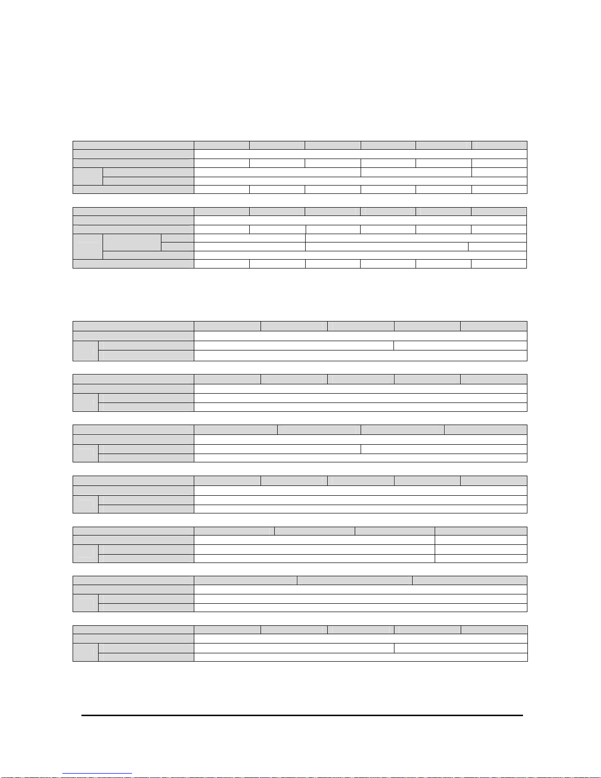
2 Electrical Parameter
Outdoor cable specifications:
Mode MDS080B(R) MDS100B(R) MDS120B(R) MDS150B(R) MDS180B(R) MDS200B(R)
Power Supply
380-415V/3N~/50Hz
Maximum Operating Current (A) 19.0 23.0 25.5 35.2 35.0 38.9
Intersection Surface(mm2)
6 10
16
Cable
Quantities 5
LRA (A) (Compressor) 61.8/64 65.5/64 74/74 65.5*2/64 74*2/74 65.5*3/64
Mode MDS220B(R) MDS240B(R) MDS260B(R) MDS280B(R) MDS300B(R) MDS320B(R)
Power Supply
380-415V/3N~/50Hz
Maximum Operating Current (A) 42.3 46.9 51.8 55.8 55.8 69.9
Separate
16 10(Master)10(Slave) Intersection
Surface(mm2) Series
/ 16(Master)10(Slave) /
Cable
Quantities 5
LRA (A) (Compressor) 65.5*3/74 74*3/74 65.5*3/74/74
65.5*5/64 65.5*5/64 65.5*4/74/74
Note: MDS260~320B(R) is combined unit, composed of master unit and slave unit; there are two ways to connect the cable that separate
connection and series connection. But you can use only the separate connection for each master and slave unit of MDS320B(R), other
combined units we recommend use the series connection. You can refer “ 8.3 electrical connection ” which show how to connect the cable.
MCC Series Indoor Units
Mode MCC008T MCC010T MCC015T MCC018T MCC020T
Power Supply
220-240V~/50Hz
Intersection Surface(mm
2
)
1.5 2.5
Cable
Quantities 3
Mode MCC025T MCC030T MCC040T MCC050T MCC060T
Power Supply
220-240V~/50Hz
Intersection Surface(mm
2
)
2.5
Cable
Quantities 3
MCK Series Indoor Units
Mode MCK010T MCK015T MCK018T MCK020T
Power Supply
220-240V~/50Hz
Intersection Surface(mm
2
)
1.5 2.5
Cable
Quantities 3
Mode MCK025T MCK030T MCK040T MCK050T MCK060T
Power Supply
220-240V~/50Hz
Intersection Surface(mm
2
)
2.5
Cable
Quantities 3
MDB Series Indoor Units
Mode MDB050T MDB060T MDB080T MDB100T
Power Supply
220-240V~/50Hz
380-415V/3N~/50Hz
Intersection Surface(mm
2
)
2.5 2.5
Cable
Quantities 3 5
MCM Series Indoor Units
Mode MCM020T MCM030T MCM050T
Power Supply
220-240V~/50Hz
Intersection Surface(mm
2
)
2.5
Cable
Quantities 3
MWM Series Indoor Units
Mode MWM008T MWM010T MWM015T MWM020T MWM025T
Power Supply
220-240V~/50Hz
Intersection Surface(mm
2
)
1.5 2.5
Cable
Quantities 3
Note:
● All cable shall be connected and fixed tightly;
● All cable can not contact any tubing of refrigerant or compressor or fan motor etc;
● All cable shall be with copper and rubber insulation material layer; intersection surface shall refer to the table as above;
Page 5
©2005 McQuay International
4
3 Installation Instruction
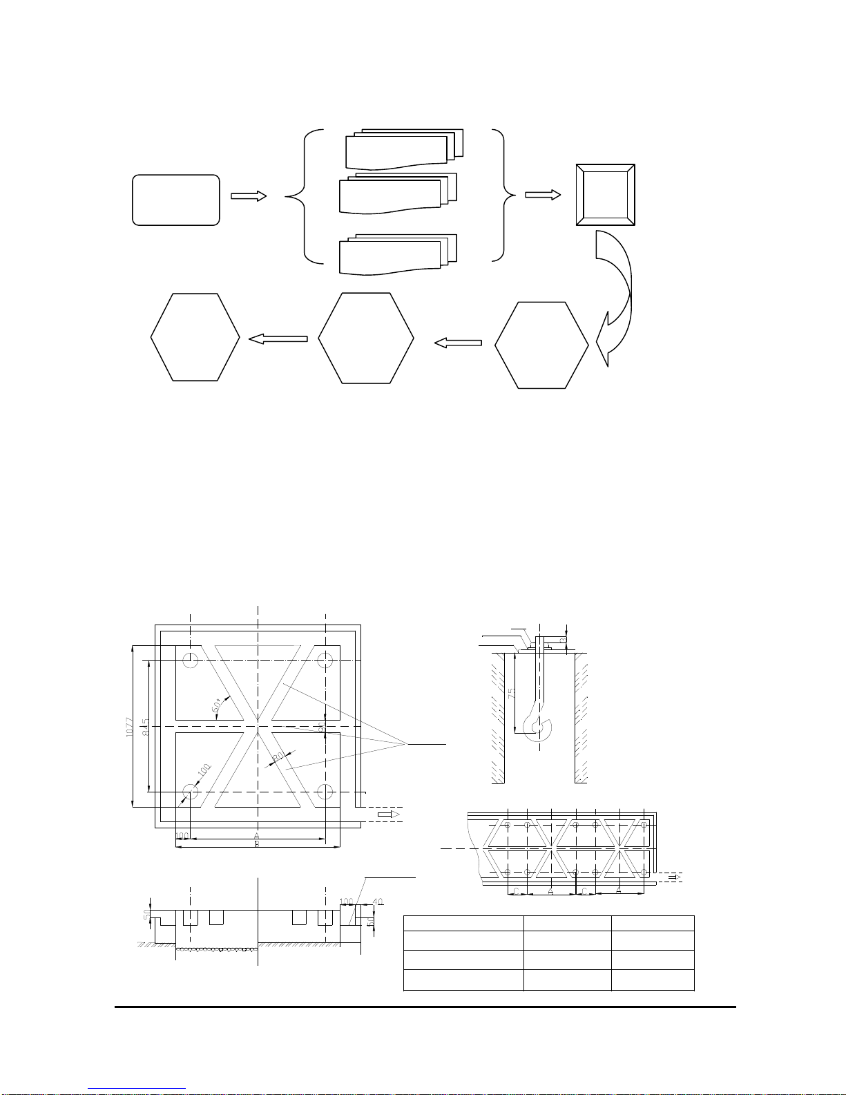
Follow up the following installation steps:
4 Outdoor unit installation
4.1 To choose location of installation
To ensure the units cooling and heating performance, follow up the below to pick up right place to install units:
● To avoid the discharge air return to air inlet, to avoid heated air discharged by other outdoor units; ensure enough space for maintenance
● To remove any barrier of air ventilation both air supply and air discharge;
● Maintain good ventilation for better heat exchange efficiency;
● Installation base shall be strong enough to support the units and prevent vibration;
● To avoid to install units at dirty and salty place;
● To avoid to install units at easy burning gas leakage place;
● Do not install units which is subject to impact by typhoon and strong wind, also to avoid the place of sunshine and snow & rain;
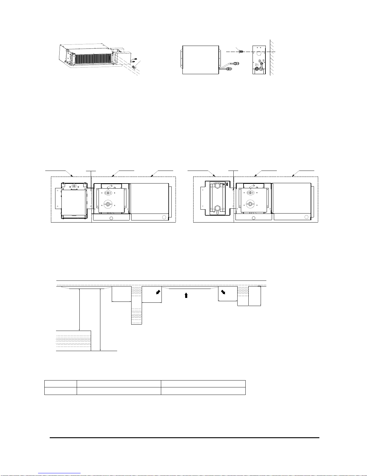
4.2 Foundation designed for installation of outdoor units
Choose the
place to install
Install the outdoor
Install the indoor
Install piping
Cable
line
Leakage
testing
Vacuum
and charge
refrigerant
Test
Running
Constructing on the ground
x
Foundation nut installing
Many units concentrated installing
Constructing on the floor
MDS200~240BR
Mode
MDS080
~
120BR
MDS140~180BR
Drain ditch
Gradient is 1/40
x
Drain ditch
1900
2100
900
1200
A
1100
1400
B
Nut
Y Trough
Undercarriage
Spring washer
Bolt mode:JA
Dimension:M12
Quantity:4
Page 6
©2005 McQuay International
5
Protective pads
>8m
>8m
Suspension ropes
(8m or longer × 2 ropes)
<40
°
<40
°
>8m
>8m
≥
≥
≥
≥
Note:1.The scale of concrete: cement : sand :macadam is 1:2:4, please put in ten φ10mm steel bar every 300mm spacing.
2.Must setting drain ditch around the foundation for drain all condensate that brought by outdoor unit.
3.The dimension C lie on installing location.
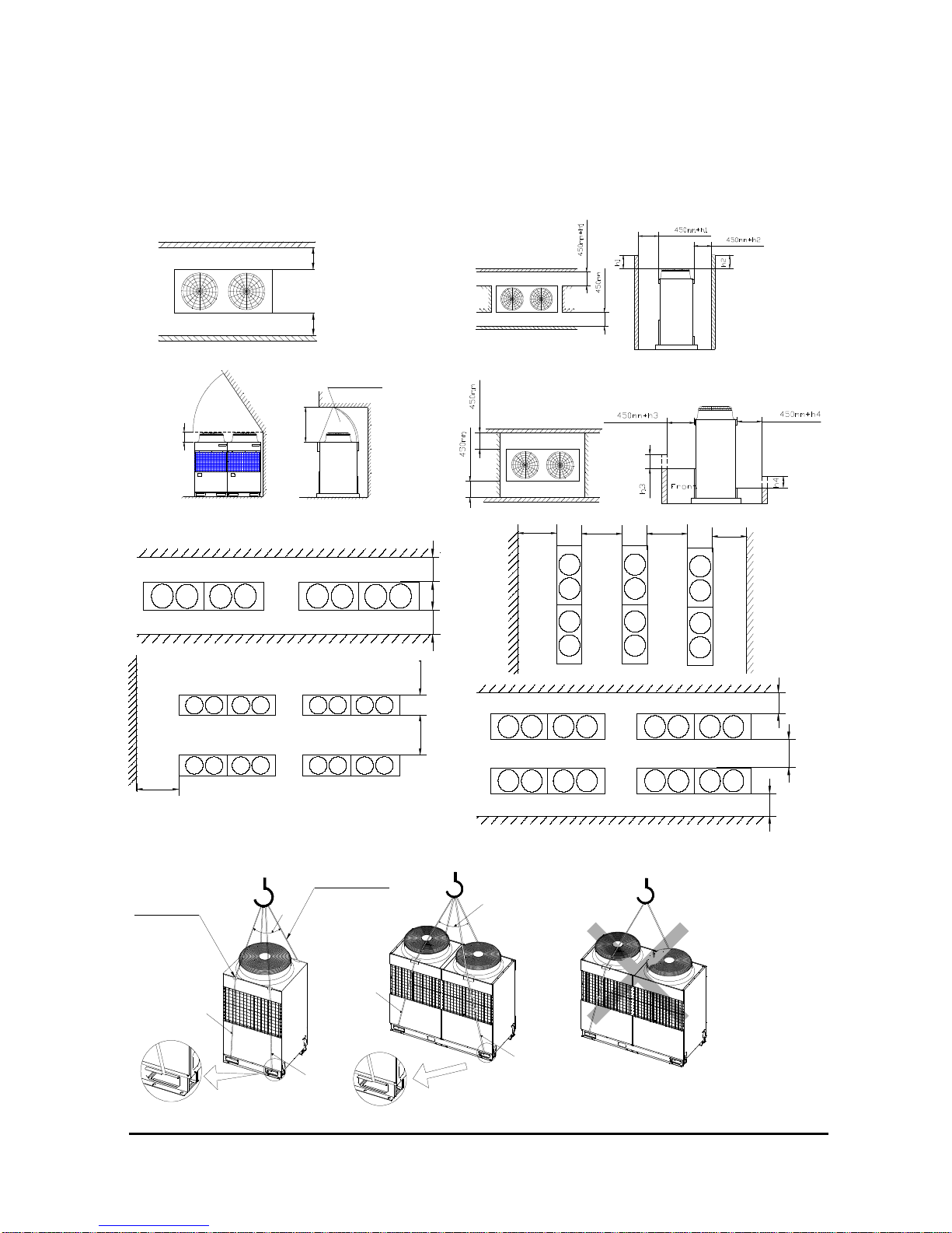
4.3 Space for installation of outdoor units
One single outdoor units can be installed in one place, many outdoors can be installed one big place, refer to the followings:
● Space for single unit
(1) Basic space required (2) When inlet air enters from right and left sides of unit
(3) When there is an obstruction above the unit (4) When unit is surrounded by walls
Space for more than one units:
4.4 Handling outdoor units
Please refer to the followings to conduct moving of units; To use 4 supporting point to move units instead of 3 points, to avoid unstable move
and units drop off;
BACK
FRONT
FRONT
BACK BACK
FRONT
FRONT
BACK
≥
600mm
≥
4
5
0
m
m
≥
9
0
0
m
m
≥
4
5
0
m
m
≥
9
0
0
m
m
≥
4
5
0
m
m
BACK
FRONT
FRONT
BACK
BACK
FRONT
FRONT
BACK
FRONT
BACK
FRONT
BACK
≥
4
5
0
m
m
≥
4
5
0
m
m
FRONT FRONT FRONT
≥
900mm
≥
450mm
≥
450mm
≥
900mm
≥
450mm
≥
450mm
≥45°
Front
Air Outlet Guide
≥
300mm
≥
1000mm
≥
≥
≥
≥
Page 7
©2005 McQuay International
6
Ball valve
(liquid side)
For φ28.6mm gas pipe, directly
connect to Tri-joint; For φ34.9mm
gas pipe, add a reducer and a
transition pipe
C
o
n
n
e
c
t
p
i
p
e
t
o
i
n
d
o
o
r
u
n
i
t
s
φ28.6mm a transiton pipe
(only for
φ
34.9mm gas pipe)
C
D
Tri-jiont
A >10mm
B >200mm
C >500mm
D>100mm
G
a
s
p
i
p
e
Elbow
L
i
q
u
i
d
p
i
p
e
B
a
l
a
n
c
e
p
i
p
e
B
To balance pipe
access valve
To units ball valve
To units ball valve
Main and slave units must be
installed in the same level
Access valve for
balance piping (φ9.52)
Ball valve (gas side)
R
e
m
o
v
e
t
h
e
p
a
n
e
l
Knock-out-hole
Knock-out-hole
Piping connection position
A
Knock-out-hole
(for connecting balance pipe)
Note:Outdoor unit transportation shall be very careful;
Do use special rope to tie the units for transportation;
Do not touch the fins of units to avoid hurt of hand;
Do keep the plastic bag from the child;
4.4 Outdoor unit Installation
● To use the solid base or supporter, considering the strength of the floor and drainage and piping layout;
● To screw bolt to fix the 4 corner of unit, to avoid the impact of strong wind and earthquake;
● To stop the vibration transfer, to take some measure to stop it , such as rubber and vibration absorber;
Warning::::
● Installation ground and base shall be strong enough;
5 Installation of the combined outdoor units
((((Suitable for Model of MDS260~320))))
Two outdoor units can be grouped as one outdoor unit, to couple with multi-indoor units; Grouped outdoor units installation is more
complicated than that of the single outdoor unit; please read the below notes carefully before installation;
5.1 Select the position of the installation for outdoor unit
Select one unit as the main unit, the other one as the slave unit; and two units shall be positioned in the same level side by side;
● Main unit and slave unit shall be installed in the same level;
● The distance between main and slave unit shall be more than 10mm ;
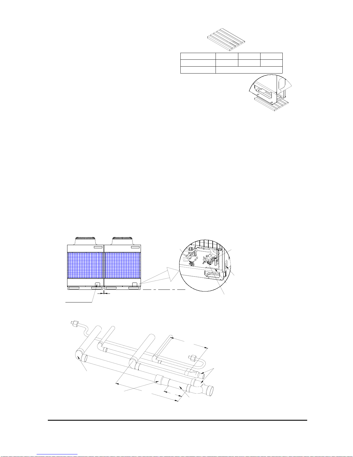
5.2 Piping connection of the outdoor units
Accessory copper parts are packed with the outdoor units; piping connection includes gas, liquid and balance piping connection between
the main and slave units; all piping shall be with insulation material and avoid any damage of this insulation material;
5.2.1 Gas and liquid piping connection
● Gas and liquid piping connection with the units, please refer to the concerned chapter of “ installation of refrigeration piping”;
Gas and liquid piping shall be connected paralleled, shown as below. The dimensions of the straight pipe connected to the Tri-joint must
meet the requirements below;
Unit model
Absorber quantity
Absorber SPEC
280×180×15mm
MDS080~150
4
Rubber absorber
6
MDS180~2408MDS260~320
Page 8
©2005 McQuay International
7
indoor
unit
MEX box
screw joint
liquid pipe
gas pipe
IN
OUT
10mm
drain direction
5.2.2 Balance piping connection
●
Balance piping must be installed; balance piping shall be connected through the hole of side panel or base panel or the piping connection
position with the other outdoor unit;
●
Balance piping shall be installed horizontally and orderly, and shall be lower than the access valve for balance piping;
●
Protect the balance piping carefully and avoid touching any other parts, especially need to keep the piping from touching the wall of hole;
●
Balance piping connection with the unit is shown in above drawing;
●
Balance pipe should be vacuumed before open the access valve;
5.2.3 Insulation and Protection for connection piping
●
All connection piping shall be well insulated;
All piping shall be well protected to avoid any bumping, trampling and rubbing with the surround when vibrating. Otherwise the piping may be
damaged, and affect the unit performance and safety, further more other safety problems may occur;
6 Indoor Unit Installation
6.1 To choose the position of installation
To follow up the below instructions:
●
Ensure air flow everywhere of room;
●
No barrier for air flow;
●
Enough maintaining space for installation;
●
Wall or ceiling shall be strong enough to support indoor units;
●
Do not expose to sunshine place;
●
Do not install units at oil and steam gas place;
●
Do not install leakage and easy burning gas place;
●
Do not install around the Hi frequency equipment place;
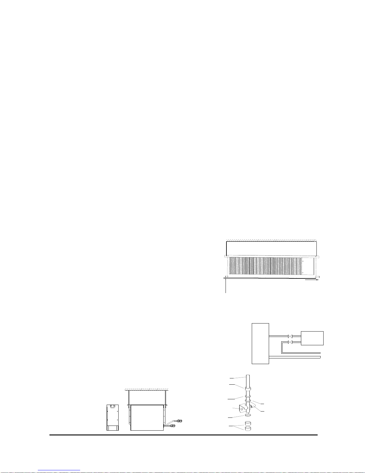
6.2 Installation of Indoor Unit
6.2.1 Installation of MCC-T series indoor units
This type indoor units shall couple with duct working of air supply and air return; also can add the heating coil and heater;
6.2.1.1 Indoor Unit
●
To check the accessories are ready;
●
To install the hooker and ensure it strong enough to support unit;
●
Install the unit and check it installed horizontally; ensure the slope of the drainage
piping , as shown in the Fig.
Note: a. Ensure piping and air duct working are most efficient length and units shall be
installed in the middle position of the room;
b. When installation of the indoor units, to ensure the distance shall be larger than 1 m between return air inlet and heat exchanger;
●
To install the piping and drainage piping;
●
Do not use the damaged copper tube or dirty copper tube; To avoid long time expose to the air ; Only get the concerned preparation ready,
to start the open valves, connector ,copper cup and cover etc;
●
This series product need connect a MEX box out of the machine ,as shown in the figure:
The MEX box contain an electric-expanding valve in it. If the indoor unit is installed in the bedroom,
setting the MEX box out of the bedroom can efficient lower the noise of refrigerant flowing and expanding.
When install the MEX box, make sure the box vertical and set it fast. The distance between the MEX
box and indoor unit could not exceed the length-limit of the expanding valve cable. The cable has a plug
to connect the control box of the indoor unit.
There are some manners to install the MEX box:
steeve
nut
washer
hole for screw
washer
nut
washer
hook
SUSPENDING BY STEEVES
Page 9
©2005 McQuay International
8
6.2.1.2 Duct Working Installation
●
Air Supply duct working installation
To pick up the selected air distributor or diffuser to meet the application requirements;
●
Air Return duct working installation
To connect with return air inlet of indoor units, the other end connecting with return air inlet of ceiling;
●
Insulation of duct working
Both air supply and return duct working shall be equipped insulation material with aluminum foil;
6.2.1.3 Electrical Heater and heating coil installation
The way to install electrical heater and heating coil is almost the same, both need to connect to air outlet of indoor units as shown as
followings:
6.2.2 Install MCK-T Series Indoor Unit
● Note :
a) Ensure the space for installation;
b) Ensure no barrier , and good ventilation is a must;
Please refer to the below figure;
≥
0.5m
≥
1.0m
H
≥
0.5m
≥
0.5m
≤
0.3m
obstacle
floor
indoor unit
girder
indoor unit
To refer to the above installation dimension to ensure the performance of units as much as possible;
H
means height from the MCK panel to the floor , it is different in indoor unit models , please refer to the below table;
MCK MODEL MCK010T~MCK020T MCK025T~MCK060T
H
≤
2.8m
≤
3.0m
The supports shall carry weight 4 times larger than the indoor units to avoid unnecessary vibration and reduce the noise;
●●●● Installation instruction
a) To keep indoor units from the source of heat and vapor;
b) To measure the position of fixing and drill hole in the ceiling and fix the units tightly;
SCREW SETTING ON INDOOR UNIT
SCREW
SCREW SETTING ON WALL
SCREW
jiont
jiontelectrical heater
indoor unit
heating coil
return air
indoor unit return air
WATER INLET
WATER OUTLET
Page 10
©2005 McQuay International
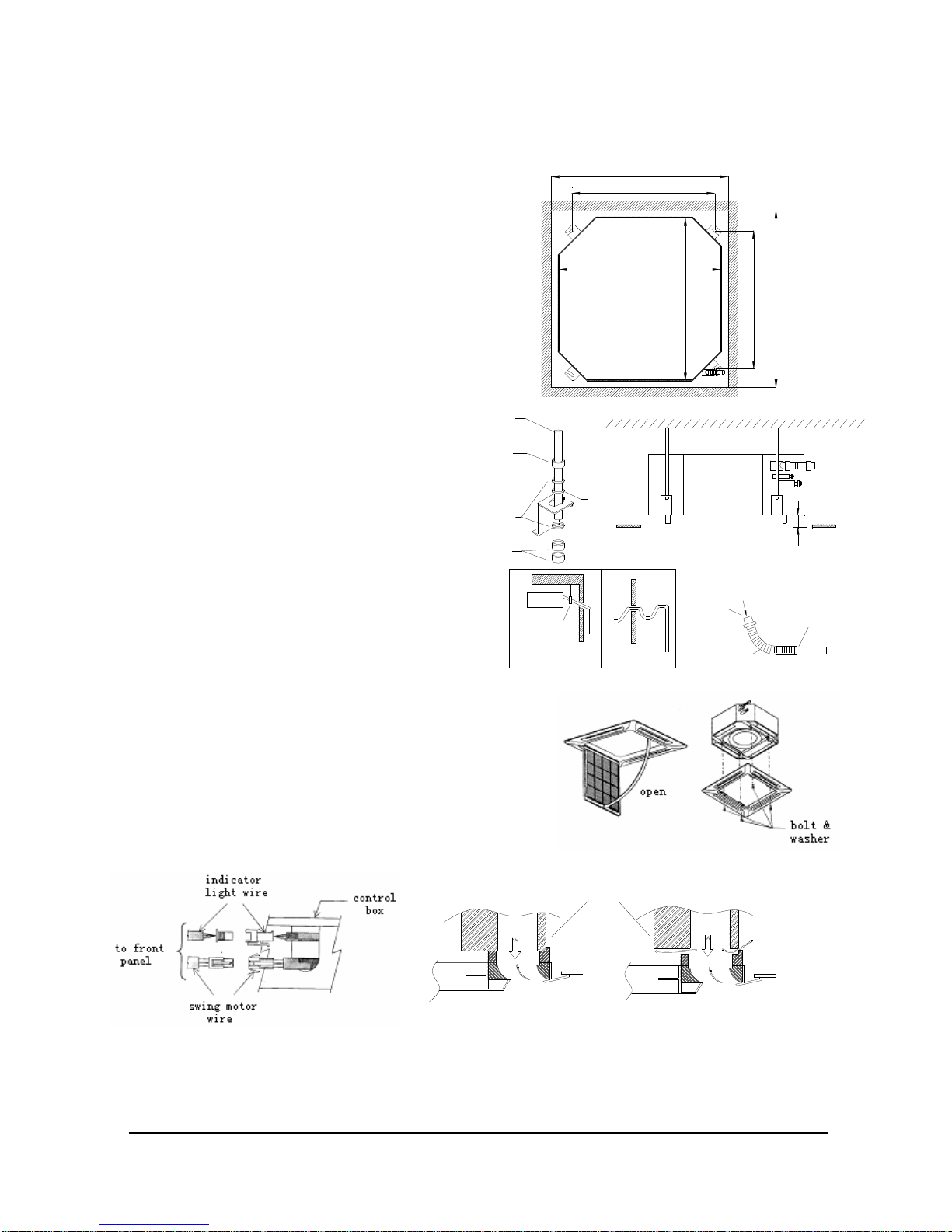
9
(machine dimension)820mm
(
m
a
c
h
i
n
e
d
i
m
e
n
s
i
o
n
)
8
2
0
m
m
790.0
(drill hole in ceiling) 890.0mm
6
2
0
.
4
(
d
r
i
l
l
h
o
l
e
i
n
c
e
i
l
i
n
g
)
8
9
0
.
0
m
m
indoor unit
ceiling
3
5
m
m
nut
washer
steeve
nut
washer
Right
flow
flow
Ceiling
Ceiling
Wrong
Cool air
Indoor unit
Cool air
Indoor
Pipe clamp
Right Wrong
c) The paper temperate shall be measure dimension before usage;
d) Ensure the paper temperate is the same dimension as hole dimension in the ceiling;
e) Before the completion of ceiling decoration, leave the paper temperate with the indoor unit;
f) Ensure the distance between the hang pole is 620.4mm×790.0mm。
g) To ensure use screw to fix the indoor units tightly;
h) To adjust distance between the bottom panel and ceiling is less than
35.0mm。
i) To check installation horizontally, and indoor units are fixed tightly without
dropping off and vibration;
j) To cut the same shape of paper temperate in ceiling;
k) Drainage shall be smooth piping and slope installed;
l) To avoid drainage piping bent , shall be straight;
m) To install the drainage piping, do not exert too strong force;
n) It shall be installed diameter 20 flexible host to connect
outside part of drainage piping, as shown as Figure;
o) Drainage piping shall be covered with insulation material
( thickness: 8.0mm polyphone plastic material ) , to avoid
the dropping off of the condensing water;
p) To connect the drainage host and flexible host;
q) To fill in some water to piping to test the leakage;
r)
After testing, to connect the other end of flexible host to
indoor units;
【
Note】 In this type of indoor units, a water pump is used to help to drain
the
condensing water, to install unit horizontally to avoid leakage of water and
condensing water dropping off;
【
Note】This series product need connect a MEX box out of the machine,
please refer to page 7 of this manual;
Installation of front Panel
●
To install the front panel , please check the piping connecting direction first;
Follow the direction of the piping connection direction;
●
To remove the paper temperate;
●
To remove the air filter and grill of front panel;
●
To use 4 screw bolt to fix the frame of front panel tightly;
●
To connect the indicator light with indoor unit and fan swing motor with indoor units respectively;
【
Note】 Ensure the frame of the front panel is fixed tightly to avoid the leakage of cool and dropping of condensing water;
There are also the hole for fresh air and exhaust air for connection with outside in indoor unit, but as for air piping, and only be the other
side of refrigerant piping connector;
drain pipe
drain & leakage test
fill water
flexible pipe
Page 11

©2005 McQuay International
10
Supply air Supply air
Supply airSupply air
Return air
9
0
1
1
9
10
7
0
2
0
1
1
9
20 115115
10
2
0
50 50 50 50 50
PCD φ140
Air outlet Fresh air inlet
φ
1
0
0
Return air and supply air direction:
Drawings for piping connector and its dimension ( unit: mm) :
【
Note】Do not close all air outlet of indoor unit when start to run the unit to avoid the frost of evaporator;
To ensure the thickness of insulation material and no leakage allowed; Fresh air shall be less than 20%;
Air tightness of outlet of supply air:
Total 4 air outlet can be sealed by insulation material but more than 2 air outlet closed will cause abnormal operation of units;
Open the front panel, to seal the air outlet in front panel;
To ensure the length of insulation material is the same length of the air outlet;
To extend the insulation material to cover the gas more than 10mm but not touch the air grill; there is no need to extend insulation material
more than 10 mm;
Installation of air inlet grill:
Before installation of air inlet grill, to install the air filter;
To ensure the right side to face the grill;
Be careful to install the air filter in the frame of air filter supporter;
To fix the filer with the front panel;
To fix the grill and consider the service friendly to open the grill;
Installation of drainage:
a) Drainage piping shall be with slope 1/100 ;
b) To fix the drainage piping with long screw bolt;
c) After installation, to test the leakage drain to make sure it work;
d) Only in cooling mode, there will be detect of drainage status;
6.2.3 Installation of MDB-T series indoor unit
MDB050~100T installation as shown as below:
Duct return air
Indoor unit
Ceiling
height
Static pressure
box
Duct
discharge air
Page 12

©2005 McQuay International
11
≥
300mm
≥
400mm
PULL P ULL PULL P ULL
≥
1000mm
≥
250mm
≥
5
0
0
m
m
Ceiling mounting
Floor standing mounting
1
0
m
m
1
6
6
m
m
10mm
1
0
m
m
10mm
1
0
3
0
0
3
0
0
6
2
1
1
0
Ceiling
Top panel
● To check the accessories are ready
●●●● To choose the location for installation
●●●● To install the hook
●●●● To install the indoor unit
●●●● To install the refrigerant piping
If units expose to air more than 15 s, units shall be vacuumed firstly;
●●●● Duct working design
Well designed duct working can reduce noise level and efficiency; when doing this, please consider the internal air pressure drop shall equal
to internal static pressure, otherwise air flow may be too big or too small, and cause the unit failure; It could adjust the fan speed to make them in
balance;
●●●● Installation of drainage piping
a) Slope is required as 1/100 ;
b) To use suspending bolt to fix the long drainage piping;
c) After installation, to run the leakage test is necessary;
d) Only in cooling mode, there is a need to detect the status of drainage;
6.2.4 Installation of MCM-T series indoor unit
● To check the accessories are ready
● To install the indoor unit
There are two type of installation : vertical floor standing or horizontal ceiling mounting:
If the indoor unit is installed as right below , ensure the space for service :
● Horizontal Ceiling mounted
(1)
To remove the air return grill , frame , side panel
and suspending panel as shown as below:
(2)
To fix the suspending panel with screw bolt as shown as right above figure;
(3)
To fix the panel and screw bolt and install the piping , install the air return grill and frame;
(4)
To install the MEX box, this series product need connect a MEX box out of the machine,
please refer to page 7 of this manual;
●●●● Vertical floor standing
(1)
Remove the air return grill , frame , side panel and suspending panel:
(2)
To install the unit supporter and wall suspending panel, as shown right:
1
0
m
m
Drainage direction
Air return grill
Frame
Suspending
panel
Panel side
Page 13

©2005 McQuay International
12
Refrigerant pipe & drain pipe
(come out from top panel)
Wall
Refrigerant pipe & drain pipe
(come out from bottom panel)
Wall
(3)
To install the refrigerant and drain piping as shown above;
(4)
To install the electrical expansion valve as same as the horizontal installation ;
●●●● Installation of drain piping
a) Slope is a must and shall be 1/100;
b) To fix the drain piping to use screw bolt;
c) After installation , to run the water leakage test is a must;
d) Only in cooling mode, there is a need to detect the status of drainage;
6.2.5 Installation of MWM-T series indoor unit
● To check the accessories are ready
● To choose the location for installation
The indoor unit must be installed in such a way so as to
prevent short circuit of the cool discharge air with the hot return air.
Please follow the installation clearance shown in the figure. Do not
place the indoor unit where there could be direct sunlight shining
on it. Also, the location must be suitable for piping and drainage,
and be away from doors or windows;
● Mounting installation plate
Ensure that the wall is strong enough to withstand the weight of the unit. Otherwise, it is necessary to reinforce the wall with plates,
beams or pillars;
Use the level gauge for horizontal mounting, and fix it with 4suitable screws;
In case the rear piping draws out, drill a hole 65mm in diameter with a cone drill, slightly lower on the outside wall;
● Mount the unit onto the installation plate
Hook the indoor unit onto the upper portion of the installation plate (Engage the two hooks at the rear top of the indoor unit with the
upper edge of the installation plate). Ensure that the hooks are property seated on the installation plate by moving it to the left and right.
● Water drainage piping
The indoor drain pipe must be in a downward gradient for smooth drainage. Avoid situations that are likely to cause water to leak.
Page 14

©2005 McQuay International
13
Alarm
Run
Stop
2
1
1
8
1
2
【
Note】This series product need connect a MEX box out of the machine, please refer to page 7 of this manual;
6.2.6 Installation of condensing water pump
● To check the accessories are ready
● Install the anti-vibrating mounting bracket and the pump
The bracket’ figure is as following:
Fix the bracket, there is a groove in the side of the pump, hitch the pump onto the bracket. Make sure the pump set steady and
vertical;
● Water level and the state of the pump
According the water level detected by the pump self, the pump determine its work state, as following:
When the detected level is higher then 18mm, the pump start run; When the detected level is higher then 21mm, the pump send an
alarm signal to the controller of the indoor unit, and the pump continue pumping; When the detected level is lower then 12mm, the pump
stop run;
To reduce the water amount in the water plate of the indoor unit, the pump’s inlet should be lower then the drainage of the indoor unit,
as following, recommend :2mm≤h≤6mm ;
● Wire connecting
a) Connect power supply cable to the pump;
b) Connect pump Live, Neutral and Earth terminals to the mains power supply;
c) The pump must be still powered when the indoor unit is off;
d) Connect the alarm wire to the indoor unit’s controller;
outdoor
side
indoor
side
Water
leakage
Water
leakage
Water
leakage
End
dipped
into water
Drain
Page 15

©2005 McQuay International
14
Bifurcation
Indoor
unit
Controller
Distributor
Indoor
unit
Controller
● Notice
The pump cannot be used in a vary polluted environment,
and the condensing water plate of the indoor unit should be
keep clean;
7 Piping installation
Multi digital scroll --- One outdoor unit couple with multi indoor units; only the professional staff can conduct the installation;
For piping connection, there will be gas pipe and liquid pipe connection, gas pipe with horn connection and connection between pipe and
pipe;
7....1 Notes for piping installation
(1)
Copper tube material: to check the thickness and diameter , ensure the clearness of the copper tube;
(2)
To machine to vacuum the unit, It is not allowed to use refrigerant to vacuum the units;
(3)
Do not use the 2nd refrigerant piping;
(4)
Do not use any detergent to clean the refrigerant piping;
(5)
To seal the outlet of the copper tube , to avoid any dust or dirt or water to enter inside;
(6)
When install the piping work, to ensure not do it in raining day;
(7)
To avoid the bending and turning of piping;
(8)
For welding requirement, to use the right welding material to ensure the quality;
(9)
Copper tube insulation is a must to ensure the heat exchange efficiency, to avoid the drop of condensing water;
(10)
When installing the refrigerant piping, all ball valve shall be in constant closed status, before completing the leakage test and vacuum
processing, it is not allowed to open the ball valve;
(11)
When move or relocate the units, in charge the right refrigerant and ensure the refrigerant weight is requested as shown in nameplate;
7....2 Refrigerant piping system:
The below 3 structure designs are recommended:
(1) Connecting by bifurcation
(2)
Use only one distributor
Page 16

©2005 McQuay International
15
Controller
Indoor
unit
Distributor
(3)
Multi bifurcation and distributors
●
It is not allowed to connect bifurcation with distributor, as shown as below:
7....3 Connecting of refrigerant piping
●
Copper tube selection: to select the main tube and branch tube and get them connected, the table is shown as below:
Outdoor model
MDS080B(R)/
MDS100B(R)
MDS120B(R)
B(R)
/MDS200B(R)
MDS220B(R)/
MDS240B(R)
MDS260B(R)/MDS280B(R)
/MDS300B(R)/ MDS320B(R)
Outdoor and the first bifurcation
Liquid
φ
12.7
φ
15.88
φ
15.88
φ
19.05
φ
19.05
Gas
φ
28.6
φ
28.6
φ
34.9
φ
38.1
φ
41.3
Between the gas distributors
<16kW
φ
9.52
16kW≤C<22.5kW
φ
12.7
22.5kW≤C<50kW
φ
12.7
φ
15.88
Liquid
Capacity
50kW≤C<85kW
—— —— ——
φ
19.05
<9kW
φ
15.88
9kW≤C<16kW
φ
19.05
16kW≤C<22.5kW
φ
22.23
22.5kW≤C<36kW
φ
28.6
46kW≤C<50kW
—— ——
φ
34.9
50kW≤C<69kW
—— —— ——
φ
38.1
Gas Capacity
69kW≤C<85kW
—— —— —— ——
φ
41.3
Branch tube connector and indoor units
Liquid Tube diameter of indoor unit
Same as the indoor connector
Gas Tube diameter of indoor unit
Same as the indoor connector
Note: For choosing the piping materials and radial thickness, please refer to
Appendix B: R22 Piping Materials/Radial Thickness
●
Selection of bifurcation
According to the diameter tube connected, to use the below table to select the right bifurcation;
Wrong connection
Indoor unit
Controller
Bifurcation
Distributer
Wrong connection
Wrong connection
Page 17

©2005 McQuay International
16
Horizontal
Vertical
installation
<30
°
Direction A
view
Horizontal
installation
Direction A
●
Distributor selection
As the same way to select the distributor, according to the connecting piping to select distributor:
●
Bifurcation installation: Horizontal and vertical type
●●●●
Distributor installation: only available for horizontal
80
550
211
510
C
D
E
I
A
B
7
5
F
H
G
1
4
8
19.3
B
250
E
D
C
A
12.9
16.1
80
9.7
80
6.5
80
19.319.05 16.1 12.9
80 80
A
(OD)
B C D
9.7 12.7 9.712.9
F
(OD)
E HG I
25.728.928.6
25.4 22.525.7
CB
2
0
4
19.3
22.5
16.1
19.3
E
D
DISTRIBUTOR
MODEL
MDS-C1
INNER DIAMETER
(mm)
INNER DIAMETER
(mm)
Position dot
4-Weld
MDS-C3
MDS-C2
DISTRIBUTOR
MODEL
INNER DIAMETER
(mm)
A(OD)
Page 18

©2005 McQuay International
17
Outdoor
Oil trap
(every 6~8m fall of the
gas pipe set a oil trap)
Indoor
●
Limitation of the refrigerant piping length:
MDS080~320 TUBE PIPING
Total length Actual Length
≤
350m
L1+L2+...+Li+a+b+…+i
Actual Length
≤
125m
Max length
Equivalent length
≤
150m
L1+L2+... +Li+i
Length
of
tube
Equivalent length from the 1st bifurcation
to longest piping
≤
40 m
L2+L3+...+Li+i
Outdoor is in high position
≤
50 m
-
Indoor and
outdoor
Indoor is in high position
≤
40 m
-
Height
difference
Between indoors
≤
15 m
-
Note:1) When outdoor units is above the indoors units, every 6~8m fall of the gas pipe shall set a oil trap;
2) Equivalent length is the length to consider and deduct the turning pressure drip and tube pressure drop ;
Equivalent length =Actual length + number of elbow╳ equivalent length for elbow + number of trap ╳equivalent length for trap
For bifurcation, the equivalent length is 0.5m, branch piping 1.0m, elbow and oil trap ‘s equivalent as following table:
Equivalent length Equivalent length
DIA.
Elbow (m)
Oil trap (m)
DIA.
elbow (m)
Oil trap (m)
φ
9.52
0.18 1.3
φ
28.6
0.50 3.7
φ
12.7
0.20 1.5
φ
31.8
0.55 4.0
φ
15.88
0.25 2.0
φ
34.9
0.60 4.4
φ
19.05
0.35 2.4
φ
38.1
0.65 4.7
φ
22.23
0.40 3.0
φ
41.3
0.70 5.0
φ
25.4
0.45 3.4
7....4 Insulation of refrigerant piping:
To apply the enough thickness of the insulation material to wrap the liquid and gas piping, no leakage of condensing water allowed;
●
Insulation material specification as following table:
Fiberglass+Steel
Insulation Material
Adhering material+Chloroethylene foam+adhering strip
Indoor Chloroethylene insulation strip
Bare floor
Water proof flax+Bronze Pitch
Layer
outdoor
Water proof flax+galvanized panel+painting
●
Gas and liquid insulation
installation as shown as right:
H
e
i
g
h
t
d
i
f
f
e
r
e
n
c
e
b
e
t
w
e
e
n
o
u
t
d
o
o
r
a
n
d
i
n
d
o
o
r
Bifurcation
L1
a
L2 L4
L3
b c d
L5
i
e
H
e
i
g
h
t
d
i
f
f
e
r
e
n
c
e
b
e
t
w
e
e
n
i
n
d
o
o
r
s
Li
Page 19

©2005 McQuay International
18
d
i
a
m
e
t
e
r
diameter
so
Close-packed
packing
Hollow
packing
ball valve
(gas side)
A Valve stem
B Stopper pin
C Packing(accessory)
D Connecting pipe(accessory)
E Open
F Cap, copper packing
G Service port
H Flare nut
I Liquid pipe diameter
J Gas pipe diameter
K Field piping
ball valve
(liquid side)
o s
o s
A
B
C
D
J
K
H
G
I
F
E
E
●
Insulation installation for
in-build through wall
Duct dimension
Diameter 6.35~25.4mm Diameter 28.58~41.3mm
Thickness Min 10mm Min 15mm
Heat resistance
Min100℃
7....5 Ball valve installation and operation
● Ball valve operation steps:
(1)
Operate the gas side ball valve:
①
Uninstall the flange connector: to remove the flange connector from the piping;
②
To stick the seal material to cover the inlet of the ball valve flange to avoid the dirt entry ;
③
To change the hallow seal pad;
④
To fix the flange connector and hallow sealed pad and fixed ball valve of gas side with screw bolt;
(2)
Liquid side ball valve connecting: to expand the copper tube outlet, and connect the ball valve connector;
(3)
Vacuum and in charge refrigerant, ensure to open the valve completely
(4)
To calculate the additional refrigerant, and in charge to units accordingly;
(5)
To check the looseness to avoid leakage of refrigerant;
●●●● Copper tube expanded connector dimension (
Unit: mm
)
External Diameter
mm inch
Diameter
Ф
6.35
1/4” 9.0
Ф
9.52
3/8” 13.0
Ф
12.7
1/2” 16.2
Ф
15.88
5/8” 19.4
Ф
19.05
3/4” 23.3
Matching screw specification (Unit: mm)
Diameter
mm inch
Diameter
Ф
6.35
1/4” 17.0
Ф
9.52
3/8” 22.0
Ф
12.7
1/2” 24.0
Ф
15.88
5/8” 27.0
Ф
19.05
3/4” 36.0
●
When connecting liquid piping and liquid ball valve, to ensure the same axial and use wrench to fix it tightly;
Outside
diameter(mm)
Moment(N · m) Angle (˚ )
Ф
6.35
14~18 60~90
Ф
9.52
35~42 60~90
Ф
12.7
50~57.5 30~60
Ф
15.88
75~80 30~60
Ф
19.05
100~140 20~35
Page 20

©2005 McQuay International
19
8 Wiring connection
8....1 Electrical wiring connection:
Digital scroll product electrical circuit have strong power circuit and weak power circuit;
Power of indoor and outdoor units must be supplied simultaneously;
Cable of power and cable of communication shall be designed in parallel, and maintain more than 20cm between the two cables;
Cable of communication shall be screened, to avoid the interference of strong signal;total length of signal wires should be less than 1000m;
Signal wires has 2 poles of A and B, the same pole must be in one connection (A can not be connected with B);
Screened layer of signal wires should be connected with master unit until it is earthed;
Each circuit shall has its own independent fuse or air switch;
Outdoor units use 3 phase power supply cable, indoor units use 1 phase power supply cable;
Wiring diagram is shown in units;
8....2 Wiring of communication specification:
As shown as below:
A:conducting wiring(copper, intersection surface is more than 0.5mm2 or 20AWG)
B:Insulation material
C:Screen layer(efficiency shall be higher than 95%)
D:outside layer protector(PVC)
Note:
For wiring cable, refer to UL2547 and UL2791 standard;
8. 3 Electrical connection
8.3.1 For single outdoor units
Wiring cable
Fuse
Switch
Electrical connection for single outdoor unit <1>(FOR MDS080~240BR)
Two-core cable
(power circuit)
Two-core cable
(power circuit)
Switch
Fuse
Fuse
Switch
L1
Switch
Fuse
L2L1
L3
N
Power
N
L2L3
Indoor unit
Outdoor unit
Page 21

©2005 McQuay International
20
Indoor unit 1
To network or central
control (optional)
Communication cable
Screen
layer
D
e
t
a
i
l
f
o
r
T
e
r
m
i
n
a
l
A
p
c
Outdoor unit
Control box
Main PCB
Connection
port
B
p
c
A
p
c
A
i
n
B
i
n
B
p
c
B
i
n
A
i
n
Control box
A B
PCB
Control box
Indoor unit 2
B
Communication cable
Control box
A
PCB
Communication cable
JP1 of last unit on
main bus should be on
Indoor unit i
A B
PCB
JP1
A
B
A
B
A
B
Connection port
com1
c
o
m
2
c
o
m
2
com1
Connection port
Connection port
c
o
m
2
com1
Master unit
Outdoor unit
To network or central
control (optional)
A
i
n
B
i
n
B
p
c
A
p
c
Main PCB
Connection
port
Screen
layer
Communication cable
Connection
port
Slave unit
Main PCB
A
i
n
B
p
c
A
p
c
B
i
n
Indoor unit 2
Communication cable
Indoor unit 1
Control box
PCB
Connection port
A B
Control box
PCB
A B
JP1 of last unit on
main bus should be on
Indoor unit i
B
Communication cable
Control box
A
PCB
JP1
A
B
A
B
A
B
c
o
m
2
Connection port
Connection port
com1
c
o
m
2
c
o
m
2
com1
com1
8.3.2 For combined outdoor units
Note: For MDS320B(R) you can use only the separate connection, other combined units we recommend use the series connection.
8. 4 Communication cable wiring for indoor and outdoor unit;
As shown as below:
For combined unit:
Indoor unit
Switch
Fuse
Fuse
Switch
Power
L1
L2
Fuse
Switch
L1
L2
L3L2N
Fuse
Switch
L1 L3
N
L3
N
Two-core cable
(power circuit)
Switch
Fuse
Outdoor unit
Master Slave
Two-core cable
(power circuit)
Separate electrical connection for
combined outdoor unit(FOR MDS260~320B(R))
Indoor unit
Master
Outdoor unit
Two-core cable
(power circuit)
Two-core cable
(power circuit)
Fuse
Switch
L1
N
Switch
Fuse
L1
N
Power
L3
L1 L2
N
Fuse
Switch
L2L1
L3
N
Switch
Fuse
L1
N
Slave
Series electrical connection for combined outdoor unit
Page 22

©2005 McQuay International
21
PCB
BA
A B
PCB
Connect A with B, wrong
A
B
A
B
com2
Connection port
Connection port
com2
com1
Typical wrong wiring connection as shown as below:
n ot b u s stru c tru e ,co n n e ctio n ca b le
sh o u ld b e la ye d a s b u s s tr uc tu re
B
p
c
A
i
n
A
p
c
B
i
n
O u td o o r u nit
C o n tro l b o x
M a in P C B
C o n n e c tio n
p or t
S c re en
la y e r
BA
A B
P C B
C o n tro l b o x
Ind o o r u n it 1
In d o o r u n it 2
C o m m u n ic a tio n c a ble
C o m m un ic a tio n c ab le
P C B
C o n tro l b o x
A
B
A
B
C o n n ec tio n p o r t
C o n n ec tio n p o r t
co m 1
com2
com2
co m 1
B
p
c
A
i
n
A
p
c
B
i
n
Screen layer must be
grounded with outdoor unit
Control box
Connection
port
Main PCB
PCB
A
B
Neglect to
connect
A
B
Connection port
com1
com2
Page 23

©2005 McQuay International
22
8....5 IP address setting:
With set each indoor unit address code, user can define each indoor unit connecting with a same outdoor unit as indoor unit NO.0,1,2,3….
User can set the indoor unit address code by setting the SW2 switch on the control module PCB board of the indoor unit. As following:
SW
2.1
SW
2.2
SW
2.3
SW
2.4
SW
2.5
SW
2.6
Code
SW
2.1
SW
2.2
SW
2.3
SW
2.4
SW
2.5
SW
2.6
Code
SW
2.1
SW
2.2
SW
2.3
SW
2.4
SW
2.5
SW
2.6
Code
SW
2.1
SW
2.2
SW
2.3
SW
2.4
SW
2.5
SW
2.6
0 0 0 0 0 0 0 12 0 0 1 1 0 0 24 0 1 1 0 0 0 36 1 0 0 1 0 0
1 0 0 0 0 0 1 13 0 0 1 1 0 1 25 0 1 1 0 0 1 37 1 0 0 1 0 1
2 0 0 0 0 1 0 14 0 0 1 1 1 0 26 0 1 1 0 1 0 38 1 0 0 1 1 0
3 0 0 0 0 1 1 15 0 0 1 1 1 1 27 0 1 1 0 1 1 39 1 0 0 1 1 1
4 0 0 0 1 0 0 16 0 1 0 0 0 0 28 0 1 1 1 0 0 40 1 0 1 0 0 0
5 0 0 0 1 0 1 17 0 1 0 0 0 1 29 0 1 1 1 0 1 41 1 0 1 0 0 1
6 0 0 0 1 1 0 18 0 1 0 0 1 0 30 0 1 1 1 1 0 42 1 0 1 0 1 0
7 0 0 0 1 1 1 19 0 1 0 0 1 1 31 0 1 1 1 1 1 43 1 0 1 0 1 1
8 0 0 1 0 0 0 20 0 1 0 1 0 0 32 1 0 0 0 0 0 44 1 0 1 1 0 0
9 0 0 1 0 0 1 21 0 1 0 1 0 1 33 1 0 0 0 0 1 45 1 0 1 1 0 1
10 0 0 1 0 1 0 22 0 1 0 1 1 0 34 1 0 0 0 1 0 46 1 0 1 1 1 0
11 0 0 1 0 1 1 23 0 1 0 1 1 1 35 1 0 0 0 1 1 47 1 0 1 1 1 1
User can set the outdoor address code by setting the S2 switch on the PCB board of outdoor unit. The code as following:
Code S2.4 S2.5 S2.6 S2.7 S2.8 Code S2.4 S2.5 S2.6 S2.7 S2.8 Code S2.4 S2.5 S2.6 S2.7 S2.8 Code S2.4 S2.5 S2.6 S2.7 S2.8
0 0 0 0 0 0 8 0 1 0 0 0 16 1 0 0 0 0 24 1 1 0 0 0
1 0 0 0 0 1 9 0 1 0 0 1 17 1 0 0 0 1 25 1 1 0 0 1
2 0 0 0 1 0 10 0 1 0 1 0 18 1 0 0 1 0 26 1 1 0 1 0
3 0 0 0 1 1 11 0 1 0 1 1 19 1 0 0 1 1 27 1 1 0 1 1
4 0 0 1 0 0 12 0 1 1 0 0 20 1 0 1 0 0 28 1 1 1 0 0
5 0 0 1 0 1 13 0 1 1 0 1 21 1 0 1 0 1 29 1 1 1 0 1
6 0 0 1 1 0 14 0 1 1 1 0 22 1 0 1 1 0 30 1 1 1 1 0
7 0 0 1 1 1 15 0 1 1 1 1 23 1 0 1 1 1 31 1 1 1 1 1
Indoors quantity connected (outdoor S1:3~8):
Qua
-
ntity
S1.3 S1.4 S1.5 S1.6 S1.7 S1.8
Qua
-
ntity
S1.3 S1.4 S1.5 S1.6 S1.7 S1.8
Qua
-
ntity
S1.3 S1.4
S1.5 S1.6 S1.7 S1.8
Qua
-
ntity
S1.3 S1.4 S1.5 S1.6 S1.7 S1.8
1 0 0 0 0 0 0 13 0 0 1 1 0 0 25 0 1 1 0 0 0 37 1 0 0 1 0 0
2 0 0 0 0 0 1 14 0 0 1 1 0 1 26 0 1 1 0 0 1 38 1 0 0 1 0 1
3 0 0 0 0 1 0 15 0 0 1 1 1 0 27 0 1 1 0 1 0 39 1 0 0 1 1 0
4 0 0 0 0 1 1 16 0 0 1 1 1 1 28 0 1 1 0 1 1 40 1 0 0 1 1 1
5 0 0 0 1 0 0 17 0 1 0 0 0 0 29 0 1 1 1 0 0 41 1 0 1 0 0 0
6 0 0 0 1 0 1 18 0 1 0 0 0 1 30 0 1 1 1 0 1 42 1 0 1 0 0 1
7 0 0 0 1 1 0 19 0 1 0 0 1 0 31 0 1 1 1 1 0 43 1 0 1 0 1 0
8 0 0 0 1 1 1 20 0 1 0 0 1 1 32 0 1 1 1 1 1 44 1 0 1 0 1 1
9 0 0 1 0 0 0 21 0 1 0 1 0 0 33 1 0 0 0 0 0 45 1 0 1 1 0 0
10 0 0 1 0 0 1 22 0 1 0 1 0 1 34 1 0 0 0 0 1 46 1 0 1 1 0 1
11 0 0 1 0 1 0 23 0 1 0 1 1 0 35 1 0 0 0 1 0 47 1 0 1 1 1 0
12 0 0 1 0 1 1 24 0 1 0 1 1 1 36 1 0 0 0 1 1 48 1 0 1 1 1 1
●
For combined unit, set the master unit’s S2.1 as 1, and set the slave unit’s S2.1 as 0 ;
●
One address code can not be used twice, and to set the first units as 0;address and indoors quantity code of the slave unit is no need to set ;
●
Only after setting up address code, to power on to start the units ; outdoor unit (single or master one) address code is used for monitoring
multi-set units simultaneously by software.
●
1 stand for ON, 0 stands for OFF;
8....6 Setting address code with remote controller :
For indoor unit with remote controller, users can set the indoor unit address code with the remote controller:
Press the “KEY1” on the indoor unit PCB (“ON/OFF” on MWM-T series) for 5s until the unit indicator lights up, meaning having entered the
set mode. Set the running mode of the unit as “COOL” with the remote controller, and then the user can set the unit address code by setting the
fan-mode and setting-temperature with the remote controller. Different fan-mode and setting-temperature means different indoor address code;
Addr. Code Fan Setting
Temp. Setting
Addr. Code Fan Setting
Temp. Setting
Addr. Code Fan Setting
Temp. Setting
0 Low Fan 16 16 Mid Fan 17 32 High Fan 18
1 Low Fan 17 17 Mid Fan 18 33 High Fan 19
2 Low Fan 18 18 Mid Fan 19 34 High Fan 20
3 Low Fan 19 19 Mid Fan 20 35 High Fan 21
4 Low Fan 20 20 Mid Fan 21 36 High Fan 22
5 Low Fan 21 21 Mid Fan 22 37 High Fan 23
6 Low Fan 22 22 Mid Fan 23 38 High Fan 24
7 Low Fan 23 23 Mid Fan 24 39 High Fan 25
8 Low Fan 24 24 Mid Fan 25 40 High Fan 26
9 Low Fan 25 25 Mid Fan 26 41 High Fan 27
10 Low Fan 26 26 Mid Fan 27 42 High Fan 28
11 Low Fan 27 27 Mid Fan 28 43 High Fan 29
12 Low Fan 28 28 Mid Fan 29 44 High Fan 30
13 Low Fan 29 29 Mid Fan 30 45 AUTO 16
14 Low Fan 30 30 High Fan 16 46 AUTO 17
15 Mid Fan 16 31 High Fan 17 47 AUTO 18
Page 24

©2005 McQuay International
23
LEAKAGE TEST SKETCH
to indoor unit
to indoor unit
nitrogen
LO
outdoor
unit
ball valve
ball valve
liquid pipe
gas pipe
HI
service port
pressure gauge
User can cancel the address code setting by remote controller: The same way to enter the set mode. Set the running mode of the indoor
unit as “FAN”, choose Low Fan mode, then press the “OPEN” button of the remote controller, the address code set by remoter controller be
canceled. After cancel the address code set by remote controller, the address code of the indoor unit depends on the SW2 switch setting on the
control module PCB board. When setting completed, the indicator light of unit will be OFF and the mode of indoor unit is OFF;
8....7 Setting automatic-start when power transmission
Press the “KEY1” on the indoor unit PCB (“ON/OFF” on MWM-T series) for 5s to enter the set mode. Set the running mode of the unit as
“FAN” with the remote controller and choose High Fan mode, then press the “OPEN” button of the remote controller. When setting completed, the
indicator light of unit will be OFF and the mode of indoor unit is OFF;
●
Cancel automatic-start function when power transmission
Enter the set mode, Set the running mode of the unit as “FAN” with the remote controller and choose mid Fan mode, then press the “OPEN”
button of the remote controller. When setting completed, the indicator light of unit will be OFF and the mode of indoor unit is OFF;
Note:
If entered the set mode but have no operation more than 60s, it will quit the set mode;
8....8 Setting address code with wired controller
Firstly, set the mode of the wired controller as “OFF”, then press the MODE key 5s to enter the address code-setting-mode, it will display
the address code setting in the wired controller and the address code of the indoor unit; Press the key ”
△”
or “▽” to set the code(00~47), press
the key “ON/OFF” to confirm the code set; Press each other key to quit the code-setting-mode;
a) In initial state the Indoor address code is according to the SW2 switch setting;
b) When entering the wired controller address code-setting-mode first time, the wired controller will read the SW2 switch setting code value
and get this value as its setting value, user can press the key ”
△”
or “▽” to change it; Simultaneous the SW2 switch setting is invalid;
c) Enter the wired controller address code-setting-mode, press the key ”
△”
or “▽”, when the displayed value is “– –“, then user can press the
key “ON/OFF” to cancel the address code set by the wired controller; After cancel the wired controller setting the SW2 switch take effect;
d) The setting address code value is stored in the register in the indoor controller, so change the wired controller or cut the power supply will
have no effect with the code value;
Setting automatic-start when power transmission:
Turn the switch OP2 of the wired controller PCB board to “ON” or “OFF”, the
auto-start function when power transmission is activated or inactivated;
9 Air leakage test, Vacuum and Refrigerant charge
9....1 Air leakage test
To conduct the air leakage test, to shut off the ball valve firstly,
and to increase the pressure of outdoor units as shown as right:
When conducting the air leakage testing, please follow up the
followings rule, to avoid the pollute the lubricating oil;
Air leakage testing procedure Remark
Charging Nitrogen gas
1)Nitrogen gas (For R22 units:2.94Mpa),waiting for 24 hours, and observe if the
pressure is not drop, the units pass the air tightness testing; if pressure decrease, to use
soap water to detect the leakage point;
2) After charging the nitrogen gas, to use soap water to the part of welding, flange and
connection position , to see if there is any bubble occurred;
3) After air leakage testing, clear the soap water;
Do not use oxygen to increase the pressure
to avoid explosion;
To use refrigerant and nitrogen gas
1)To increase the pressure to0.2MPa,to use nitrogen gas to reach the designed
pressure (for R22, 2.94Mpa); Do not increase the pressure in one step, do it slowly and
meanwhile to observe the if there is pressure drop;
2)To use electrical equipment to detect the leakage part, such as welding part, flange
etc;
3)To use leakage detector and bubble testing at the same time;
1)It is not allowed to use other refrigerant
2)Do not use halogen blow tube (leakage can
not be detected);
9....2 Vacuum
●
Before conducting vacuum, it shall shut off all ball valve ;
Time for vacuum shall last more than 25 hours at pressure 650Pa;
●
It is not allowed to use refrigerant to vacuum;
●
To only use the vacuum pump with the reserve valve;
9....3 Charging the refrigerant
●●●● When need to charge additional refrigerant
To charge additional refrigerant due to piping;
vacuum
pump
check valve
service port
ball valve
liquid pipe
gas pipe
ball valve
outdoor
unit
compound
pressure gauge
HI
LO
to indoor unit
to indoor unit
VACUUM SKETCH
Page 25

©2005 McQuay International
24
REFRIGERANT CHARGING SKETCH
weighbridge
refrigerant
tank
compound
pressure gauge
HI
LO
to indoor unit
to indoor unit
service port
ball valve
liquid pipe
gas pipe
ball valve
outdoor
unit
refrigerant
tank
weighbridge
LO
HI
compound
pressure gauge
outdoor
unit
ball valve
gas pipe
liquid pipe
ball valve
service port
to indoor unit
to indoor unit
● How to calculate the additional refrigerant weight:
a) Copper tube diameter and additional refrigerant charging:
Liquid specification
φ
19.05
φ
15.88
φ
12.7
φ
9. 52
φ
6.35
R22 additional charging 290g/m 200g/m 120g/m 80g/m 50g/m
b) The calculation format is:
Additional Refrigerant (g)=φ19.05length of copper tube(m)╳290g/m+φ15.88 total length of copper tube(m)╳200g/m+φ12.7 total
length of copper tube(m)╳120g/m +φ9.52 total length of copper tube(m)╳80g/m+φ6.35 total length of copper tube(m)╳50g/m
c) Accuracy by 0.1kg;
●●●● Charging refrigerant steps instructions:
a)Before charging, to open all gas and liquid
ball valves;
b)When charging, please turn the bottom up
of the R22 container; as shown as followings;
●●●●Case study of adding the additional refrigerant
Liquid outside diameter Additional charging(g/m) Liquid total length (m) Additional charging (g) Total charging (g)
φ
19.05
290g/m 15 4350
φ
15.88
200g/m 20 4000
φ
12.7
120g/m 40 4800
φ
9.52
80g/m 25 2000
φ
6.35
50g/m 20 1000
16150
Total to be charged R22 weight is 16.2kg;
10 Testing Operation
Before trial running, to ensure and check the safety and record the concerned data after units is in stable operation;
10.1 Checking list before trial running
(1) Ampere of indoor & outdoor units is normal and under protection value?
(2) Power supply for indoor and outdoor units?
(3) IP address setting up for indoor units are OK ?
(4) Indoor unit is power on?
(5) Communication wiring is ok?
(6) Bifurcation is well installed?
(7) Condensing water drainage system is OK?
(8) Earthing ?
(9) Insulation testing (10Mega Ω)
(10) Power supply check (220-240V/380-415V)
(11) Only after air leakage tested, vacuum can be conducted and refrigerant charged;
(12) How many indoor units are controlled by outdoor unit controller;
(13) Outdoor unit valve is opened not?
10.2 Testing running record table
For the 1st time running, shall power on 24 hours in advance, to preheat the crankcase; When shutting off the main electrical power, only
after 2.5 hours later, can restart to run the unit;
No.
Suction
pressure(bar)
Discharge
pressure (bar)
Voltage (V) Ampere (A)
Suction
temperature(℃)
Ambient
Temp.(℃)
Checking person /
Time
1
2
3
4
5
6
10.3 Testing running symptoms and analyses:
If the followings failure symptoms happen, please check accordingly
symptoms Wiring controller Possible reason
No heating or cooling Can not select cooling or heating When one indoors units in heating, all indoors in heating mode
Fan stop when heating Defrost Fan stop running when defrosting
Pump keep running No indication Pump keep running to drain the water
Page 26

©2005 McQuay International
25
Appendix A: Dimension
MDS080,100,120,150,180,200,220,240,260,280,300,320 B(R)
Unit: mm
Model A B Model A B Model C D
MDS080/100/120B(R)/
120B(R)M
900 990
MDS150B(R)/130B(R)S/
150B(R)M/150B(R)S/
160B(R)M/160B(R)S
1200 1290
MDS180/200/220/
240B(R)
950 1990
AMDS260/280/300B/320(R)are combined units, made up by a master unit and a slave unit
Combined unit MDS260B(R) MDS280B(R) MDS300B(R) MDS320B(R)
Master unit +
Slave unit
MDS120B(R)M+
MDS150B(R)S
MDS150B(R)M+
MDS130B(R)S
MDS150B(R)M+
MDS150B(R)S
MDS160B(R)M+
MDS160B(R)S
D 990+10+1290 1290+10+1290 1290+10+1290 1290+10+1290
MCC008,010,015,018,020,025,030,040,050,060T
Unit: mm
MODEL A B C D E F G H I J FAN AMOUNT
MCC008/010/015T 690 722 1054 751 39 210 469 118 9 220 2
MCC018/020/025/030T 950 981 1314 1005 32 248 490 81 14 251 2
MCC040/050T 1300 1331 1664 1355 32 248 490 81 14 251 3
MCC060T 1560 1591 1924 1615 32 248 490 81 14 251 4
D
Detail M
Screw Hole 1420
Detail M
8-14x20 Screw
hole (for setting)
14-14x20
Screw hole
Page 27

©2005 McQuay International
26
86
1690
1611
1510
912
1
6
350
4
2
0
8
1
5
50
1400
879
40
61 107 268
131153
3
8
8
2
6
4
4-Φ13
MCK010, 015, 018, 020, 025, 030, 040, 050, 060T
Unit: mm
MODEL A B C D E F G H I J K L M
MCK010/015/018/020T 820 875 548 820 278 250 28 930 930 642 622 555 555
MCK025/030/040/050/060T 820 875 548 820 363 335 28 930 930 642 622 555 555
MDB050, 060, 080, 100T
Unit: mm
MODEL A B C D E F
MDB050T 995 957 998 1032 1063 1230
MDB060T 1195 1157 1198 1232 1263 1430
MDB080T
Page 28

©2005 McQuay International
27
MDB100T
MCM020, 030, 050T
Unit: mm
MODEL A B C D E F G H J K L M N
MCM020T 1174 75 1082 68 58 156 1214 57 670 216 319 879 517
MCM030T 1174 75 1082 68 93 156 1214 57 670 216 319 879 517
MCM050T 1674 75 1582 68 93 156 1714 57 670 216 319 1379 517
1
8
9
4-Φ13
1580
749
1669
1402
1470
8
7
0
9
4
5
5
2
0
2
9
5
1
9
0
325
1
8
55
1020
163 224
62
4
7
1
26035
2
1
6
Page 29

©2005 McQuay International
28
MWM008, 010, 015T
Unit: mm
MODEL A B C D E F G H I J K L M N O
MWM008T 799 260 198 490 246 185 124 8 56 50 319 379 50 128 132
MWM010/015T 899 260 198 590 246 185 124 8 56 50 419 495 50 128 132
MWM020, 025T
Unit: mm
MODEL A B C D E F G H I J K L M N O
MWM020/025T 1060 310 220 912 294 99 51 8 48 43 354 403 160 138 160
Electrical heater::::
Unit:mm
MODEL A B C D
HDP1.2T08-15/HDP2.4T08-15 762 704 732 844
HDP2.4T18-32/HDP3.6T18-32 1022 964 992 1104
HDP2.4T35-45/HDP3.6T35-45/
HDP4.8T35-50/HDP7.2T35-50
1372 1314 1342 1454
HDP5.4T60/HDP7.2T60/HDP10.8T60 1632 1574 1602 1714
cable inlet
suspension hole
Page 30

©2005 McQuay International
29
Heating coil::::
Unit:mm
MODEL A B C D
HWT08-15 762 704 732 818
HWT18-32 1022 964 992 1078
HWT35-50 1372 1314 1342 1438
HWT60 1632 1574 1602 1688
Indoor units EXV BOX:
MODEL MEX-15-2SAP-C/D,MEX-18-2SAP-D MEX-18-3SAP-C/D,MEX-24-3SAP-C,MEX-30-3SAP-C
OD I(mm(inch)) 6.35(1/4) 9.52(3/8)
Condensing water pump (optional accessory) MDS-CP08/CP10/CP20::::
Unit:mm
water outlet
water inlet
Rc3/4 drain pipe
suspension hole
Page 31

©2005 McQuay International
30
Appendix B: R22 Piping Materials/Radial Thickness
Type TP2M TP2Y2
Size (mm)
φ6.4 φ9.5 φ12.7 φ15.9 φ19.1 φ22.2 φ25.4 φ28.6 φ31.8 φ34.9 φ38.1 φ41.3
Size(inch)
1/4 3/8 1/2 5/8 3/4 7/8 1 1-1/8 1-1/4 1-3/8 1-1/2 1-5/8
Minimum Thickness
(mm)
0.8 0.8 0.8 1.0 1.0 1.0 1.0 1.0 1.1 1.3 1.4 1.5
The minimum thickness of the pipe in the chart is based on the PRC Standard Specification for
Drawn Tube of Copper and Copper Alloys
(GB/T1527-1997), TP2M and TP2Y2 are the marks of the material brand and state. Using this table as reference, choose the pipe that
meets the local standards and the maximum operation pressure reaches 3.0MPa.
If the unit is used in the environment which is eroded seriously, it should be thickened by 0.2mm.
The table shows the minimum thickness. If the pipe is need to be bent or drawn, which causes the thickness to thin, please add the extra
thickness appropriately.
 Loading...