

Page 1
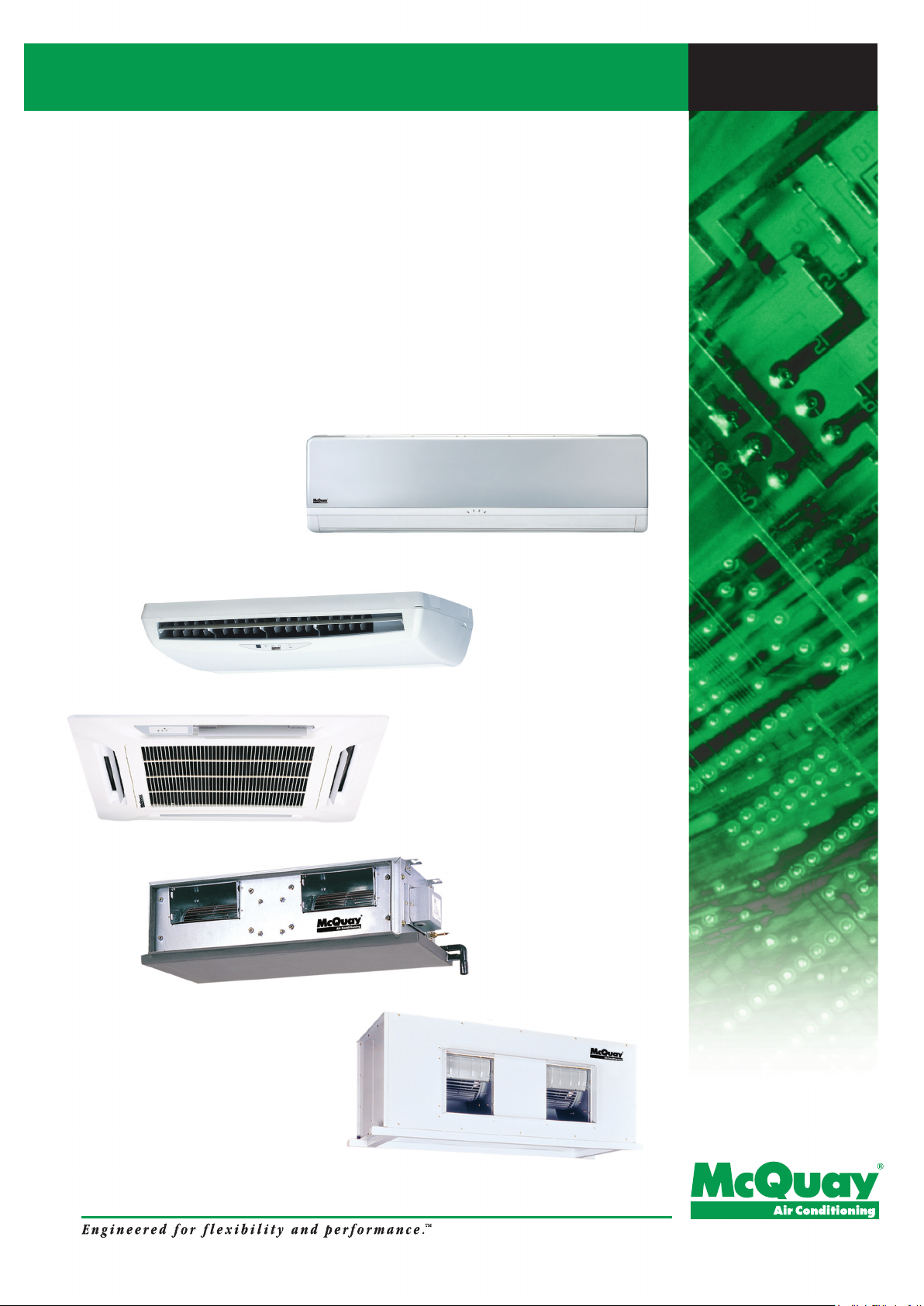
Fan Coil Units
Catalog
MFCU_(i)
Models:
MWM-G2W
MCM-DW/EW
MCK-AW/BW/CW
MCC-CW
MDB-BW
Page 2
TT
aa
bb
a
aa
b
bb
le ofle of
le of
le ofle of
T
TT
Nomenclature................................................................................................................. 1
Features ......................................................................................................................... 8
Application Information.................................................................................................. 10
Sound Data ................................................................................................................... 26
Selection Process ......................................................................................................... 29
Engineering and Physical Data ..................................................................................... 55
Performance Data ......................................................................................................... 96
Dimensional Data......................................................................................................... 148
Electrical Data .............................................................................................................. 166
Contents Contents
Contents
Contents Contents
Wiring Diagrams........................................................................................................... 171
Servicing and Maintenance .......................................................................................... 179
Troubleshooting............................................................................................................ 180
Eploded View and Parts List ........................................................................................ 181
This manual supercedes MFCU-2009
Note : Installation and maintenance are to be performed only by qualified personnel who are
familiar with local codes and regulations, and experienced with this type of equipment.
Caution: Sharp edges and coil surfaces are a potential injury hazard. Avoid contact with them.
Warning : Moving machinery and electrical power hazard. May cause severe personal
injury or death. Disconnect and lock off power before servicing equipment.
"McQuay" is a registered trademark of McQuay International. All rights reserved.
Bulletin illustrations cover the general appearance of McQuay International products at the time of publication.
We reserve the right to change design and construction specifications at any time without notice.
c 2010 McQuay International. All rights reserved throughout the world.
Page 3
NomencNomenc
Nomenc
NomencNomenc
Production spec variation
Type of ref. connection
X : Not applicable
Electrical
A : 220 - 240V/1Ph/50Hz
F : 380 - 415V/3Ph/50Hz
U : 220 - 240V/1Ph/50Hz/60Hz
lala
la
lala
turtur
tur
turtur
ee
e
ee
M
WM 025 G2
W AB
-
A
Piping
H : 4 pipes system
Model Type
W : Chilled water fan coil
Series
G2 : G+ series
Capacity
025 : 18,000 Btu/h (Cooling)
Model Name
X
WM : Wall mounted split type
CK : Ceiling cassette split type
CM : Ceiling exposed split type
CC : Ceiling concealed split type
DB : Ducted split type
Brand
M : McQuay
1
Page 4
Product Line-Up
MWM-G2W Product Line-Up
CLASSIFICATION
MWM
MODEL NAME
007G2W
010G2W
015G2W
020G2W
025G2W
301W
Control
NOMENCLATURE
PCB W2_L
Valve Application only
AXALxxxx xxxxx x x
AXAKxxxxx xxxx x x
AXALxxxx xxxxx x x
AXAKxxxxx xxxx x x
AXALxxxx xxxxx x x
AXAKxxxxx xxxx x x
AXALxxxx xxxxx x x
AXAKxxxxx xxxx x x
AXALxxxx xxxxx x x
AXAKxxxxx xxxx x x
AXAExxx x xxx x x
AXADxxx xxxx x x
Turbo
Auto Air Swing
G17 Cooling
HANDSET
G17 Heat Pump
CONNECTION
Left piping
1/2" BSP (female) brass adaptor
FILTER
Ionizer
Nanosilver + Nanovis filter
PANEL
+
Light Grey Chasis
Pure White Chasis
MARKING
Std Marking (CE)
G2 silver coated facelift
2
Page 5

Product Line-Up
MCM-DW/CBW/EW Product Line-Up
CLASSIFICATION
MCM
MODEL NAME
020DW
025DW
030DW
040DW
050DW
007CBW
010CBW
015CBW
015EW
020EW
025EW
CONTROL
NOMENCLATURE
UCW - W2.0
Valve / Valveless Application
AXCExx x xxx
AXCFxx xxxxx
AXCG xx xxx
AXCHxx x xxx
AXCIxx x xxx
AXCExx x xxx
AXCFxx xxxxx
AXCG xx xxx
AXCHxx x xxx
AXCIxx x xxx
AXCExx x xxx
AXCFxx xxxxx
AXCG xx xxx
AXCHxx x xxx
AXCIxx x xxx
AXCExx x xxx
AXCFxx xxxxx
AXCG xx xxx
AXCHxx x xxx
AXCIxx x xxx
AXCExx x xxx
AXCFxx xxxxx
AXCG xx xxx
AXCHxx x xxx
AXCIxx x xxx
UXBFxxx xxx
UXBGxx x xxx
UXBHxx x xxx
UXBFxxx xxx
UXBGxx x xxx
UXBHxx x xxx
UXBFxxx xxx
UXBGxx x xxx
UXBHxx x xxx
AXAC x x
AXADxx x xxx
AXAC x x
AXADxx x xxx
AXAC x x
AXADxx x xxx
G17 Cooling
Without Controller
x
x
x
HANDSET
G17 Heat Pump
SLM 3 Cooling
Netware 3 (Cool/Heat)
SLM 3 Heat Pump
FILTER
CONNECTION
3/4" BSP (female) union
xxx
xxx
xxx
MARKING
Saranet filter
Std Marking (CE)
3
Page 6
Product Line-Up
AXBA
AXBA
AXBA
MCK-AW/AWH/CW Product Line-Up
MCK
CLASSIFICATION
CONTROL
MODELNAME
020AWAXBExxxx xxxxxx
025AWAXBExxxx xxxxxx
030AWAXBExxxx xxxxxx
040AWAXBExxxx xxxxxx
050AWAXBExxxx xxxxxx
020AWH AXAA xxxxxxx x
025AWH AXAA xxxxxxx x
030AWH AXAA xxxxxxx x
040AWH AXAA xxxxxxx x
050AWH AXAA xxxxxxx x
010CW AXAB xxxx xx xxx
015CW AXAB xxxx xx xxx
020CW AXAB xxxx xx xxx
NOMENCLATURE
UCW‐W2.0
Control(dependonpanel)
Autoairswing
Valve/ValvelessApplication
CONNECTION
4pipesystems
MARKING
PLCKAW‐NNET3
StdMarking(CE)
3/4"BSP(female)brassunion
MCK‐AW
PLCKAW‐NSLM3HP
PANEL
PLCKCW‐NSLM3HP
MCK‐CW
PLCKCW‐NG17Cooling
MCK‐AWH
PLCKAW‐NG17Cooling
PLCKAW‐NG17HeatPump
PLCKAWH‐NG17HeatPump
PLCKCW‐NG17HeatPump
4
Page 7
Product Line-Up
MCC-CW Product Line-Up
CLASSIFICATION
MCC
MODEL NAME
010CW
015CW
020CW
025CW
028CW
CONTROL
NOMENCLATURE
Cool/ Heat
UCW - W2.0
Without Controller
Valve / Valveless Application
AXAKx x xx xxxx
AXBCxxx xxx xxx
AXAJxxx x xxxx
AXACx xx xxxx
AXBAxxxx x xxx
AXAKx x xx xxxx
AXBCxxx xxx xxx
AXAJxxx x xxxx
AXACx xx xxxx
AXBAxxxx x xxx
AXAKx x xx xxxx
AXBCxxx xxx xxx
AXAJxxx x xxxx
AXACx xx xxxx
AXBAxxxx x xxx
AXAKx x xx xxxx
AXBCxxx xxx xxx
AXAJxxx x xxxx
AXACx xx xxxx
AXBAxxxx x xxx
AXAKx x xx xxxx
AXBCxxx xxx xxx
AXAJxxx x xxxx
AXAAx xx xxxx
AXBAxxxx x xxx
HANDSET
SLM 3 Cooling
Netware 3 (Coll/Heat)
SLM 3 Heat Pump
Left piping
CONNECTION
Right piping
FILTER
MARKING
Saranet Filter
Std Marking (CE)
3/4" BSP (female) adaptor
5
Page 8

Product Line-Up
MCC-CW Product Line-Up
CLASSIFICATION
MCC
MODEL NAME
030CW
038CW
040CW
050CW
060CW
CONTROL
NOMENCLATURE
Cool/ Heat
UCW - W2.0
Without Controller
Valve / Valveless Application
AXAKx x xx xxxx
AXBCxxx xxx xxx
AXAJxxx x xxxx
AXAAx xx xxxx
AXBAxxxx x xxx
AXAKx x xx xxxx
AXBCxxx xxx xxx
AXAJxxx x xxxx
AXAAx xx xxxx
AXBAxxxx x xxx
AXAKx x xx xxxx
AXBCxxx xxx xxx
AXAJxxx x xxxx
AXAAx xx xxxx
AXBAxxxx x xxx
AXAKx x xx xxxx
AXBCxxx xxx xxx
AXAJxxx x xxxx
AXAAx xx xxxx
AXBAxxxx x xxx
AXAKx x xx xxxx
AXBCxxx xxx xxx
AXAJxxx x xxxx
AXAAx xx xxxx
AXBAxxxx x xxx
HANDSET
SLM 3 Cooling
Netware 3 (Coll/Heat)
SLM 3 Heat Pump
Left piping
CONNECTION
Right piping
FILTER
MARKING
Saranet Filter
Std Marking (CE)
3/4" BSP (female) adaptor
6
Page 9
Product Line-Up
MDB-BW Product Line-Up
CLASSIFICATION
MDB
MODEL NAME
075BW
100BW
125BW
150BW
CONTROL
NOMENCLATURE
UCW - W2.0
Without Controller
Valveless Application
AXAA x x x x x x x x
AXABxxxx xx x x
AXAA x x x x x x x x
AXABxxxx xx x x
FXAA x x x x x x x x
FXABxxxx x x xx
FXACxxxxx x xx
FXADxxxxx x xx
FXAA x x x x x x x x
FXABxxxx x x xx
FXACxxxxx x xx
Brazing (OD 28.6mm, 1 1/8")
CONNECTION
Left piping
Right piping
Horizontal flow
DISCHARGE
Vertical flow
FILTER
Saranet Filter
MARKING
R15/R29 Filter
Std Marking (CE)
7
Page 10
FF
eaea
ea
eaea
turtur
tur
turtur
F
FF
Space Saving
Different types of fan coil units are designed to be both versatile and space saving to suit every interior design. Ceiling
concealed type for the sophisticated, luxurious floor space saving, all kind of interior decoration; ceiling exposed type for
economical and space saving installation; etc.
Zone Control
These fan coil units can be installed in different zones as each unit operates independently. Zone control on energy
saving, different comfort requirement; better air distribution needs can therefore be easily achieved.
Standardisation Of Fan Coil Unit Control
The fan coil unit controller is standardized using W2 I.C, which enables the selection of valve / valveless and cooling /
heating applications. This allows the user to choose the desired application by just plugging in or removing the jumpers
at certain connectors on the PCB. The advantages of these units are lesser inventory for finished goods stock and spare
parts. For more details, please refer to General Installation guide.
Unique Features For MWM Series
Easy Installation
The wall mounted fan coil unit is easily installed because of its compact size, slimness and light weight. Slim and short
outdoor unit can be easily installed even in a narrow balcony and passageway and yet have a stable profile.
Space Saving
No space is required on either floor or ceiling. This newly developed super slim design for wall mounting maximises floor
space usage and enhance ceiling appearance where ceilings are low.
eses
es
eses
Quiet Operation
Cooling comfort is improved by whisper-quiet operation which is achieved by a tangential fan.
Excellent Air Distribution
Air discharge direction can be adjusted in four directions, manually or automatically by using LCD remote control, coupled
with good air flow, the unit provides excellent air distribution.
Facilitated Maintenance Ensured
The new design cassette filter is slide-out type which can be easily removed at the air inlet grille for cleaning. Maintenance
is easy for electrical components, piping and wiring as these are all easily accessible by merely removing front plastic
panel.
Wireless Remote Control
The compact LCD transmitter is able to operate the air conditioner unit within the distance of 9 meters. Fan motor speed
can be set at low/medium/high or automatic. Sleep mode automatically increase set temperature since room temperature
is lower at night thus achieving comfort surrounding. Air flow direction can be controlled automatically. Room temperature
is controlled by electronic thermostat. The unit can be preset to on and off automatically for maximum of 15 hours by using
timer on/off.
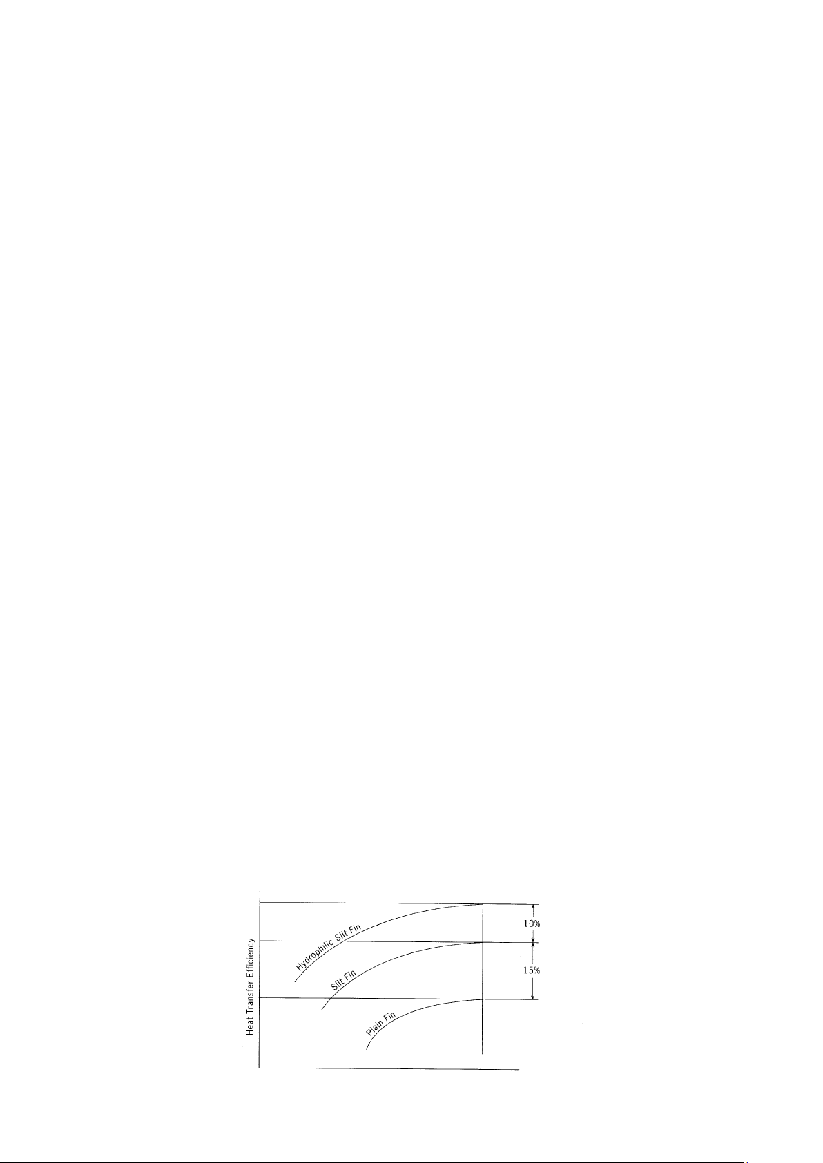
Slit Fin
The unique Hydrophilic slit fin has greatly improved the air flow and the contact surfaces with the air thus to boost the
cooling capacity.
8
Page 11

Unique Features For MCK Series
Built In High Head Drain Pump
The unit comes with a built in high head drain pump. Condensate water can be pumped up to 700mm and drain out
smoothly.
4-way Air Discharge And Air Swing
These features greatly improve the air distribution in the conditioned space.
Wireless And Wired Controller Option
Wireless Handset is the standard controller. However if wired controller required, Netware3 & SLM3 wired controller is a
wise choice(optional).
Unique Features For MCM-DW/EW Series
2-way Air Discharge And Air Swing
The 2-way air discharge couple with the air swing function, provide better air distribution in the conditioned space.
Easy Maintenance
The air filter and components can be easily accessed from the bottom of the unit. This make servicing and maintenance
become a simple task.
Wireless And Wired Controller Option
Wireless Handset is the standard controller. However if wired controller required, Netware3 & SLM3 wired controller is a
wise choice(optional).
Unique Features For MCC Series
Elegance And Prestige
As the unit is installed above the ceiling with only the supply and return air grille exposed to view, the air conditioned space
will appear as elegant and prestigious as a centralized air conditioned area.
Evergreen Design
This unit will never become obsolete as the unit is completely concealed away. Interior decoration for maximum aesthetic
beauty as well as interior design is easily achieved.
Superior Air Distribution
As the conditioned air can be distributed to every corner of the area by air duct, this will ensure more pleasant living
environment, thus provide extra comfort to the occupants.
Optional Duct Accessories
The optional duct accessories makes the ducting and installation work so easy.
Wired Controller
Netware3 & SLM3 wired controller offers simple and flexibility in controlling the unit.
Unique Features For MDB-BW Series
Superb Air Distribution
These units are designed with high air flow and static, enables adequate distribution of air to the desired space. Providing
comfort to every corner of the room.
Reliability
The structures are strong and robust to ensure the product operation life.
Versatile
Multiple rooms can be cooled together by just using one unit of MDB.
9
Page 12
√
AA
pplicapplica
A
pplica
AA
pplicapplica
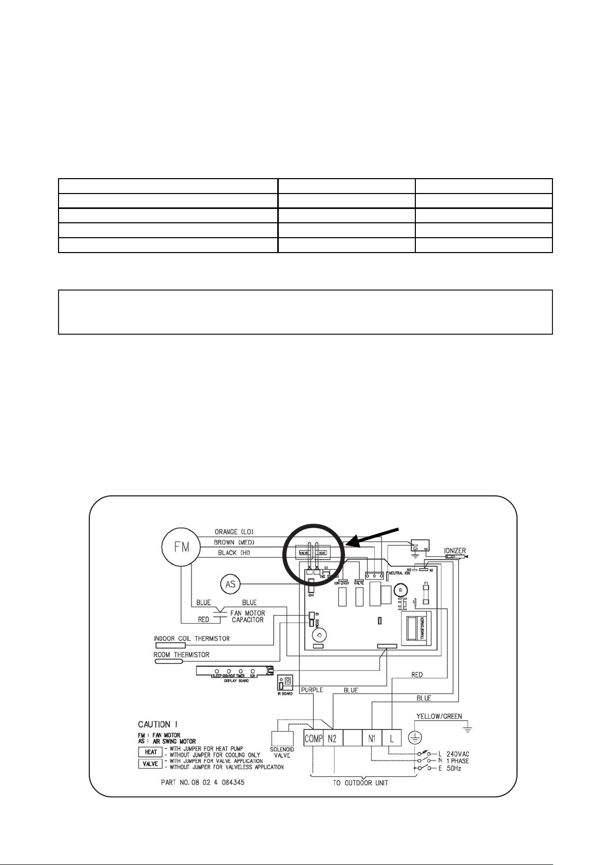
General Installation Guide
System Configuration
The standard controller board (W2) comes with a VALVE jumper and a HEAT jumper. The system can be
configured as the jumper selection listed below:
Heatpump Mode & Valve Application
Heatpump Mode & Valveless Application
Cooling Mode & Valve Application
Cooling Mode & Valveless Application
Jumper Remained X Jumper Removed
VALVE & HEAT Jumper Location
tion Inftion Inf
tion Inf
tion Inftion Inf
Disconnect the power supply to the unit before attempting to connect the wiring
oror
or
oror
mama
ma
mama
CACA
CA
CACA
tiontion
tion
tiontion
HEAT Jumper VALVE Jumper
UTION !UTION !
UTION !
UTION !UTION !
√√
√ X
X √
XX
Model: MWM - G2W / 301W
1. VALVE jumper is plugged into JVLV connector on the emergency switch board.
2. HEAT jumper is plugged into JMODE connector on the emergency switch board.
Model: MCK-AW/AWH/CW, MCM-DW/CBW/EW and MCC-CW
1. VALVE jumper is plugged into JVLV connector on the main board.
2. HEAT jumper is plugged into OD connector on the main board.
Model : MWM 007 / 010 / 015G2W (IONIZER)
10
Page 13
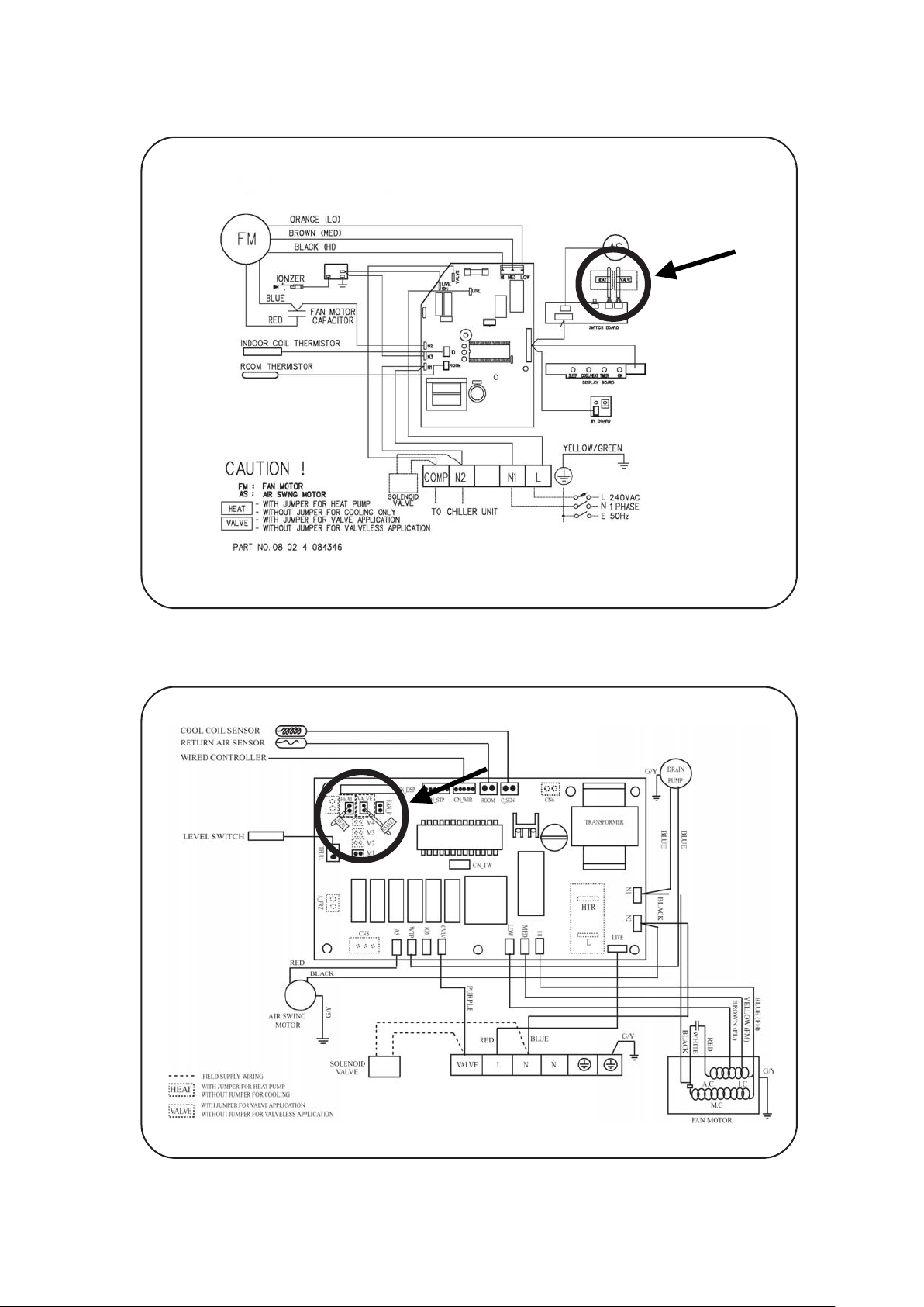
Model : MWM 020 / 025G2W (IONIZER)
Model : MCM Series / MCC Series / MCK-AW/CW
11
Page 14
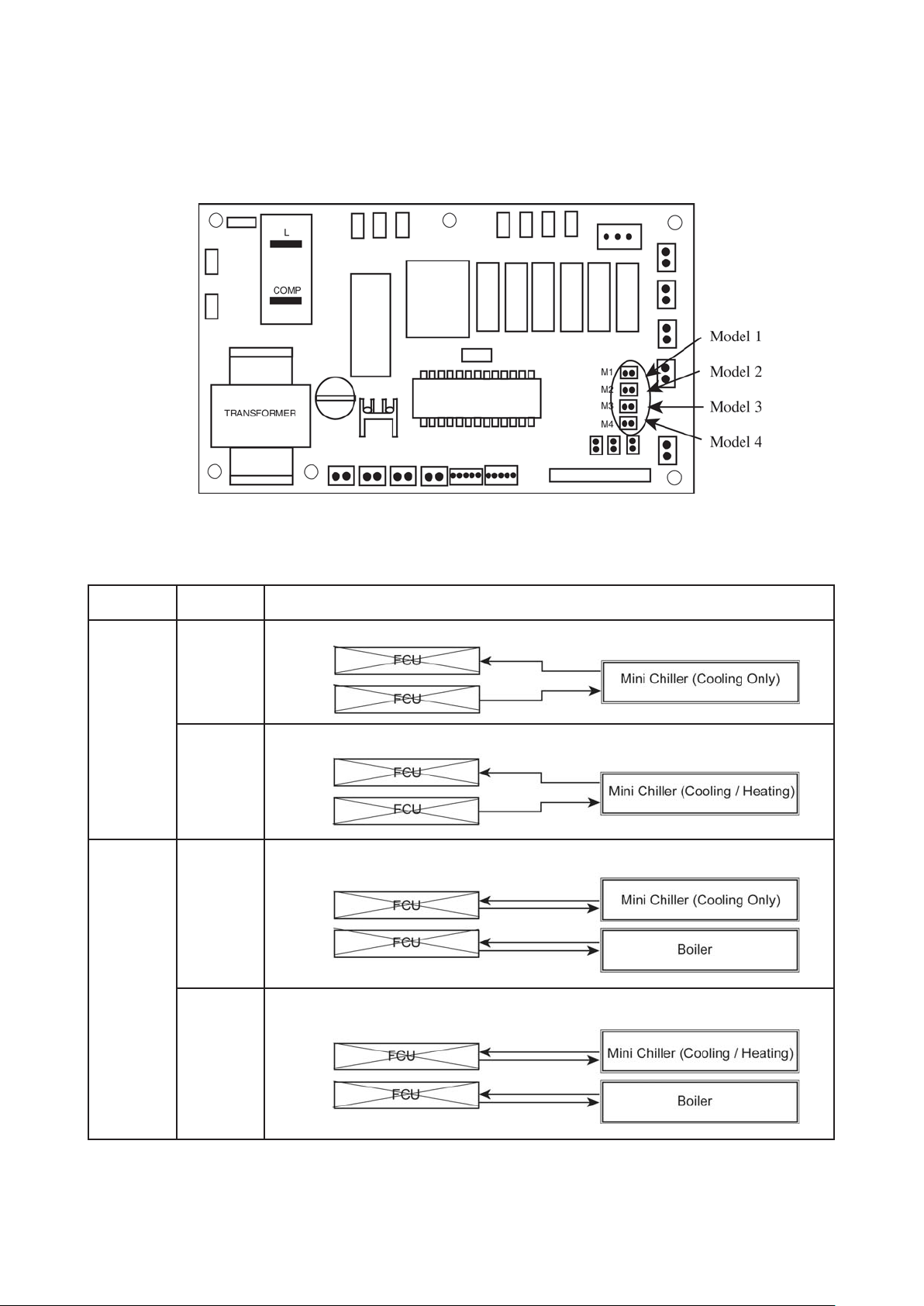
MCK-AWH 4 pipes system controller board setting
A) Model selection
The standard controller board (W2.0) comes with a default setting for model selection. Please select the model
accordingly by using jumper.
System Model Function
2 Pipe
System
4 Pipe
System
M1 Model 1
M2 Model 2
M2 Model 2
M4 Model 4
Cooling or Heating
Cooling or Heating with Auxiliary Heater
Cooling Only with Boiler
Cooling or Heating with Boiler
12
Page 15
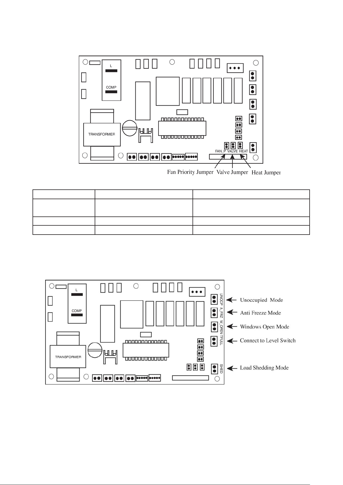
B) Valve, Heat and Fan priority selection
Jumper With Jumper (Default) Without Jumper
Fan Priority Jumper User set speed or lower fan if auto Fan stop when thermostat cut off
mode is selected
Heat Jumper For Heat pump For cooling only
Valve Jumper For Valve control (Model 1,2,3 & 4) For valveless control (Model 1 & 2)
C) Others
The controller board comes with other option.
i) Unoccupied Mode
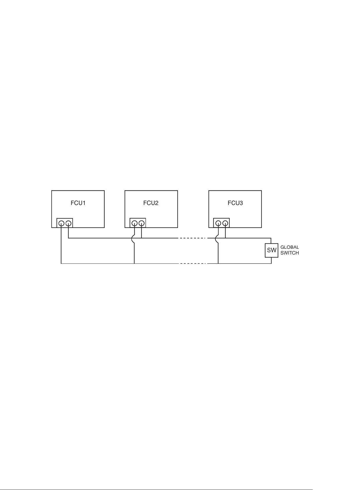
If the dry contact is closed, the Unoccupied mode is activated and vice versa. When Timer On is active, system
goes back to Occupied mode.
The dry contact connection points can be connected parallel with other fan coil unit (FCU) boards. If the dry
contact is closed, Unoccupied mode will be activated on all fan coil units that are connected parallel as shown in
figure below.
13
Page 16
ii) Anti Freeze Mode
Anti Freeze operation has the highest priority among all unit operation. Anti Freeze operation will be activated
only if dry contact is closed and vice versa.
iii) Window Open Mode
The dry contact connection points can be connected in parallel with other fan coil unit (FCU) boards. If the dry
contact is closed, Window open mode will be activated on all the fan coil units which are connected in parallel as
shown in figure below.
iv) Load Shedding
The dry contact connection points can be connected in parallel with other fan coil unit (FCU) boards. If the dry
contact is closed, Load shedding mode will be activated on all the fan coil units which are connected in parallel
as shown in figure below.
Global Unoccupied, Global Window Open and Global Load Shedding operation could also be activated via the
network communication bus line by master controller with or without the above connection.
NOTE :
i) Auto Fan Mode is only applicable in Model 3 only. ( Cooling only with Boiler)
ii) Fan mode is not available in valveless control.
iii) Wired handset (Netware and SLM) has an indoor room sensor. Avoid locating the wired handset at isolated
places where room temperature reading will be inaccurate.
14
Page 17
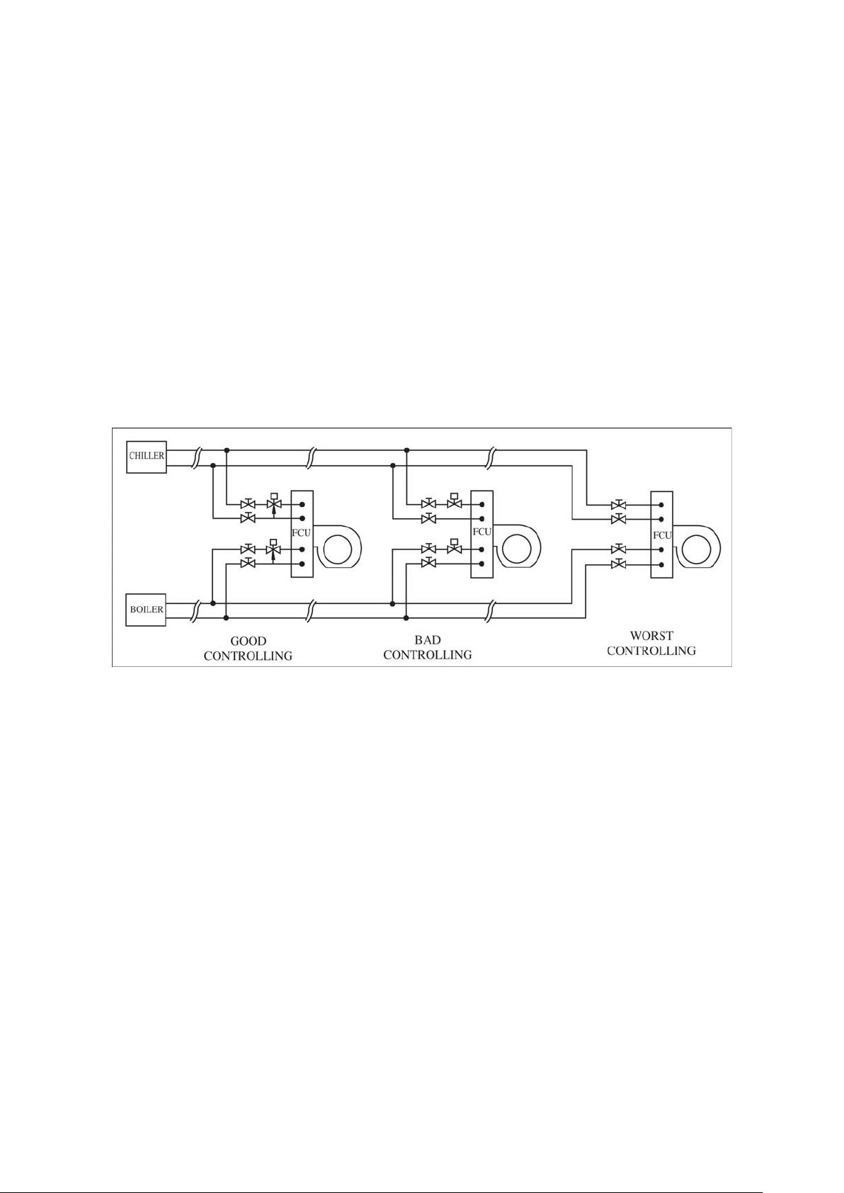
Water Piping Connection
The indoor unit is equipped with water outlet and inlet bare connection. There is an air-vent for air purging that is
fitted at the outlet water header.
3 ways solenoid valve is required for cycling off or bypass the chilled water.
Black steel pipe, polyethrene pipe, PVC pipe and copper tube recommended in field installation.
All types of piping and connection must be insulated by polyurethane (ARMAFLEX type or equivalent) to avoid
condensation.
Do not use contaminated or damaged pipe and fitting for installation.
Some main fitting components are needed in the system to enhance the capacity and ease of service, such as
gate valve, balancing valve, 2 ways or 3 ways solenoid valve, filter, strainer etc.
15
Page 18

Preliminary Site Survey
Electrical supply and installation is to conform to LOCAL AUTHORITY's (e.g. National Electricity Board) CODES
and REGULATIONS.
Voltage supply fluctuation must not exceed ± 10% of rated voltage. Electricity supply lines must be independent
of welding transformers which can cause supply fluctuation.
Ensure that the location is convenient for wiring and piping.
Mounting
For ceiling mounted models, locate a position where piping and ducting work can be kept to a minimum.
Ensure that overhead supports are strong enough to hold the unit's weight. Position hanger rods and check for
alignment with the unit. Check that hangers are secure and that the base of fan coil unit is level in two horizontal
positions.
Piping
Drain and water piping must be accurately connected.
Please refer to "Specification Sheet" for piping sizes.
Piping Support
All water mains must be adequately supported to carry the necessary weight involved, provisions must be
made by the installing contractor to allow for adequate free movement of all vertical and horizontal risers and
run outs. Due to the fact that cold water will be circulated through the water mains, a sizeable movement of the
water mains can be expected due to contraction. If for example, the piping is rigidly supported with no provision
for movement, it is very possible that the tubing of fitting may be broken causing water leakage in the conditioned spaces throughout the building.
Coil Venting
Each standard basic unit coil is equipped with a manually operated air vent which is installed at the end of a
small copper line leading into the highest point of the coil. By means of this valve, air may be vented manually,
from the coil to keep it operating at full capacity. When water is first introduced into a coil, air is sometimes
trapped in the coil tubing. This trapped air will reduce cooling capacity and create "Bubbling" or "Clanking"
noise within the units. To release air trapped in the coil, press the air vent head to allow air to flow out of the air
vent opening. Release when a steady stream of water appear.
Electrical Connection
As wiring regulations differ from country to country, please refer to your LOCAL ELECTRICAL CODES for field
wiring regulations and ensure that they are complied with. Besides, take note of the following general precaution:
1) Ensure that the rated voltage of the unit corresponds to the name plate before commencing wiring work.
2) Provide a power outlet to be used exclusively for each unit and a power supply disconnect and a circuitbreaker for over-current protection should be provided in the exclusive line.
3) The unit must be EARTH to prevent possible hazards due to insulation failure.
4) All wiring must be firmly connected.
16
Page 19

General Operation Guide
Start-Up
The following procedure must be completed before any attempts is made to put the entire system Into operation:
1) Piping connections completed.
2) Electrical connections completed.
3) Duct connections completed.
4) Auxiliary drain pans in position where required.
5) Drain line draining into drain pans.
6) Filters correctly installed and free of construction debris.
7) Motor-blower assembly rotates freely.
8) Unit Hydro-statically tested and air vented.
Starting The Fan Coil Unit
1) Turn on the switch of water pump.
2) Start water chiller.
3) Operate the fan coil unit by turning on the fan and set the control switch to get the desired speed.
4) Inspect the duct and piping condition and rectify problem (e.g. vibration, noise, etc.) if exist.
Servicing And Maintenance
Fan coil units are designed to operate continuously with minor routine maintenance. Since fan coil units cool
the discharging forced air, the efficiency with which the units operate is directly related to the amount of air
passing through the coil.
Air Filters
The function of the air filters is to remove foreign matter such as dirt, soot, pollen and certain other impurities
from the air passing through it. A clogged or dirty filter not only fails to do the job for which it is designed, but
restricts the flow of air over the coil.
The importance of cleaning the filter before it becomes clogged must be greatly stressed. The frequency with
which a filter should be cleaned will depend upon the amount of dust and foreign material that enters a unit, and
this depends upon location and situation.
The washable viledon or saranet filter may be cleaned by tapping the filter on a solid surface to dislodge heavy
particles. Wash under stream of warm water, with detergent if necessary. Dry it thoroughly before replacing.
Fan Motor
The fan motor is pre-lubricated and sealed at the factory. Therefore, no lubricating maintenance is required.
Coils
Clean coil unit by brushing between fins with a nylon brush. Brushing should be followed by cleaning with a
vacuum cleaner. The coil may also be cleaned by using a high pressure air hose and nozzle if a compressed air
source is available. It should be pointed out that if suitable air filter is used and taken care of properly, the coils
need no cleaning.
Drain Pipe
The drain pipe should be checked before operation of unit is begun. If it is clogged, steps should be taken to
clean the debris so that condensate will flow out easily.
Replacement Of Parts
Replacement of parts are available through your local dealers. When ordering parts, you must supply
1) Model name of the unit.
2) Serial number of the unit.
3) Part name and number.
17
Page 20
Controller
Type Of Controller Vs Type Of Fan Coil
MODELS STANDARD CONTROLLER OPTIONAL CONTROLLER
MWM - G2W G11 (Wireless) NETWARE3 / SLM3 (Wired)
MWM 301W G7 (Wireless) NETWARE3 / SLM3 (Wired)
MCK - AW / AWH / CW G7 (Wireless) NETWARE3 / SLM3 (Wired)
MCM - DW / CBW / EW G7 (Wireless) NETWARE3 / SLM3 (Wired)
MCC - CW NETW ARE3 / SLM3 (W ired) -
MDB - BW
Self Diagnosis Table
Error Indication Cool LED 7 Segment Display
Room Sensor error (short/open) Blinks 1 times E1
Pipe Water Sensor Error (short/open) Blinks 2 times E2
Water Pump Error Blinks 6 times E6
Pipe Water Temperature Fault Blinks 5 times E5
* Window Open Activated Blinks 3 times -
* Antifreeze Mode Activated Blinks 7 times -
* Load Shedding Activated Blinks 8 times -
Without Controller
* Only applicable for 4-pipe system
18
Page 21
Operation Guide For G17
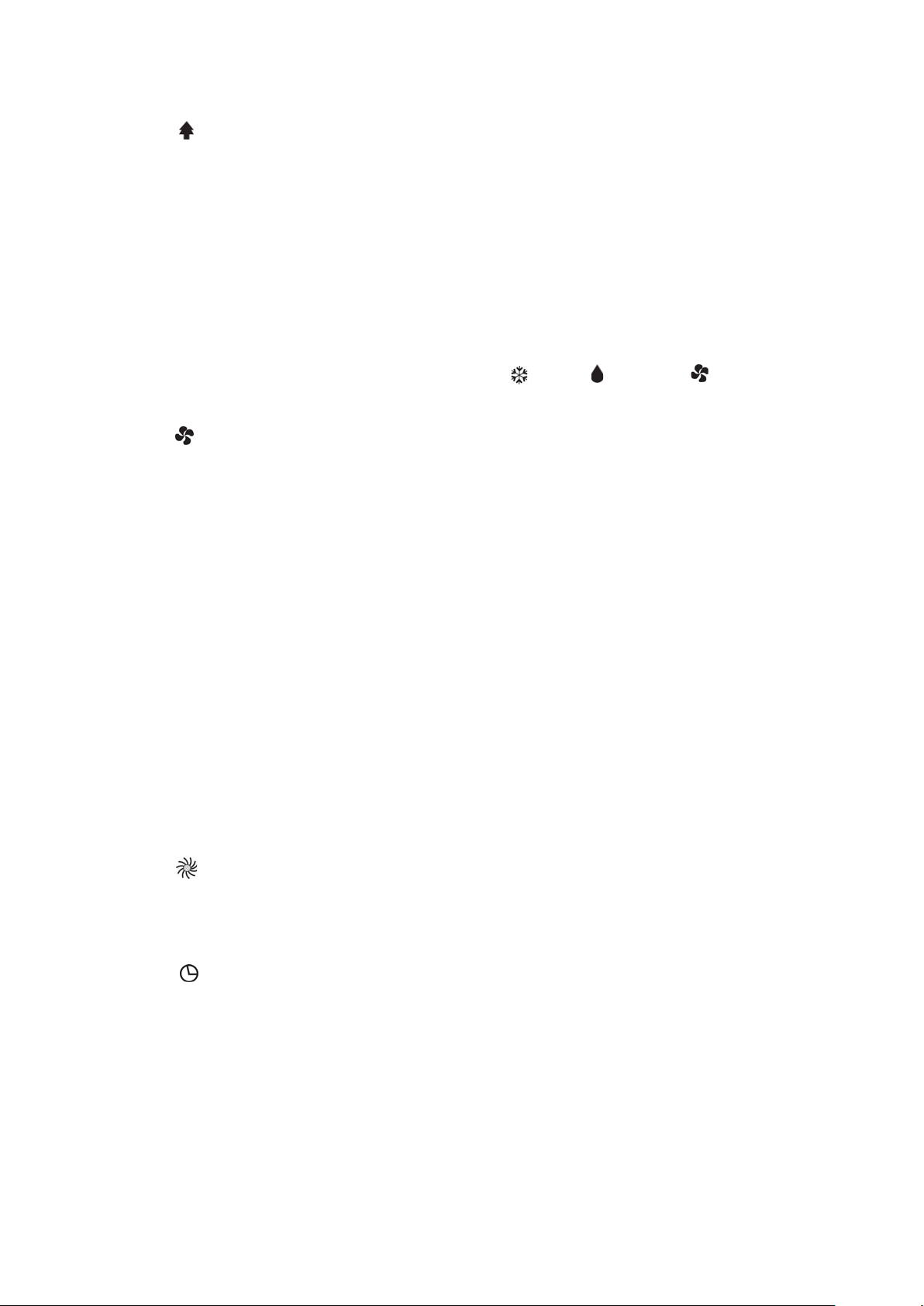
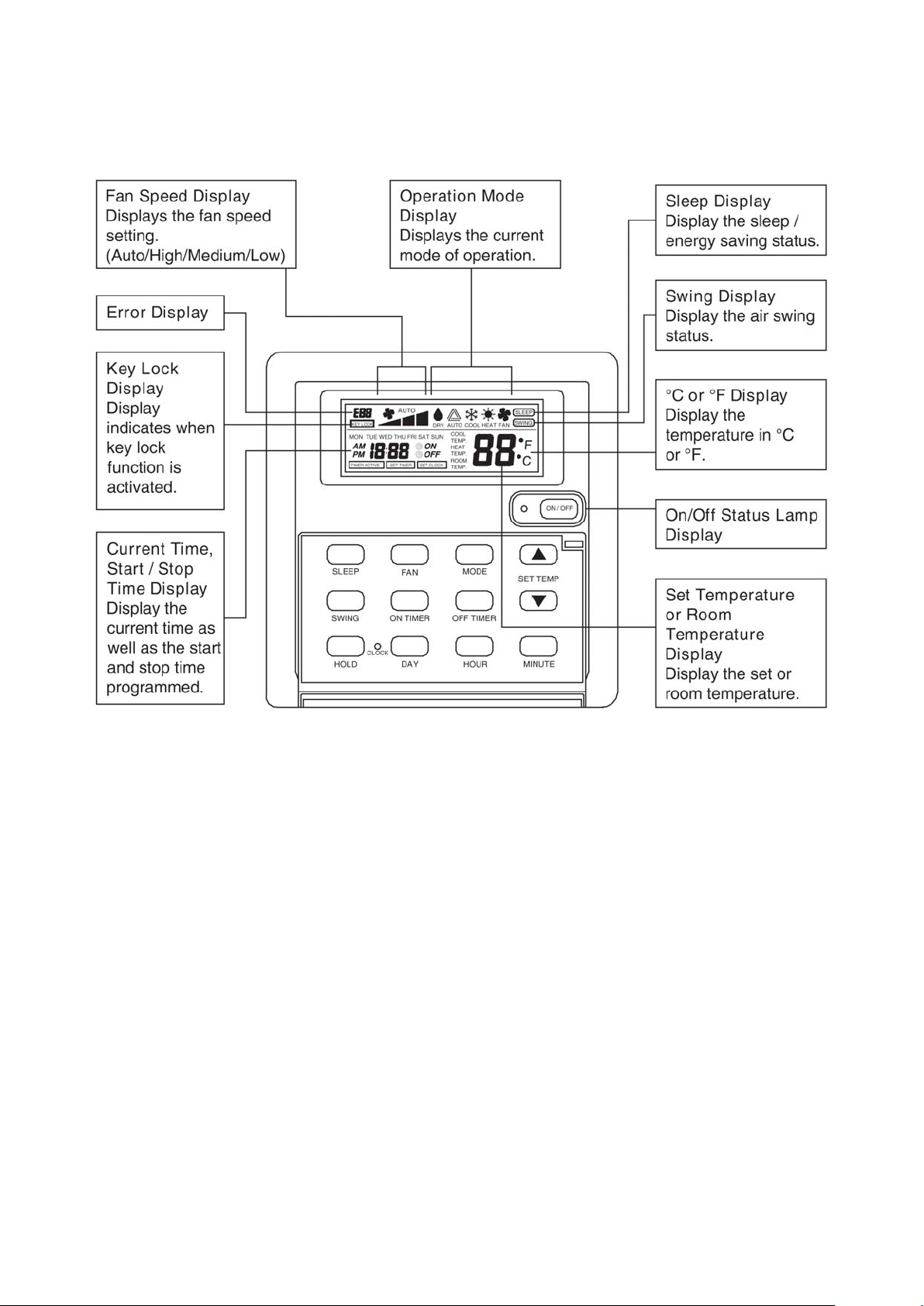
1. Transmission Source
• The source where the signal will be transmitted.
2. Signal Transmission Indication
• Blink to confirm that the last setting has been transmitted to the unit.
3. Temperature Setting
• To set the desired room temperature, press the S or T button to increase or decrease the set temperature.
• The temperature setting range is from 16°C to 30°C (optional setting 20°C to 30°C).
4. Personalize Setting
• Press and hold for 3s, then will blink. Press again to cycle between and .
• Set the desire setting, then leave the handset for 4s without pressing any key and it will save the setting
into the programme.
• Press once to activate the P1 setting, press again to cycle between P1 and P2.
• Press any key to deactivate the personalize setting.
5. Automatic Air Swing (optional)
• Press the SWING button to activate the automatic air swing function.
• To distribute the air to a specific direction, press the SWING button and wait until the louver move to
the desired direction and press the button once again.
6a. Silent Function
• Press for quiet operation.
• Fan speed turn to minimum speed.
• Press again to deactivate the function.
19
Page 22
6b. Ionizer Function
• Press button to activate the negative ion function, which will refresh the indoor air effectively.
7. Sleep Mode Setting
• Press the SLEEP button will activate the sleep mode function. This function is available under COOL,
HEAT and AUTO mode.
• When the unit is operating under cooling mode, the set temperature is increased by 0.5°C after 30
minutes, 1°C after an hour, and 2°C after 2 hours.
• When the unit is operating under heating mode, the set temperature is decreased by 1°C after 30
minutes, 2°C after an hour, and 3°C after 2 hours.
8. Operating Mode
• Press the MODE button to select the type of operating mode.
• For cooling only unit, the available modes are: COOL ( ), DRY ( ) and FAN ( ).
9. Fan Speed Selection
• Press the button continuously will toggle the fan speed in the following order:
Low → Med → High → Auto
• Stop pressing when the desired fan speed appears on the display screen.
10. “ON/OFF” Button
• Press one to start the air conditioner unit.
• Press again to stop the unit.
11. Timer Cancel
• Press the TIMER CANCEL button to cancel the on timer setting.
12. OFF Timer Setting
• Press the OFF TIMER button will activate the off timer function.
• Set the desired off time by pressing the OFF TIMER button continuously.
13. ON Timer Setting
• Press the ON TIMER button will activate the on timer function.
• Set the desired on time by pressing the ON TIMER button continuously. If the timer is set to 7.30am,
the air conditioner will turn on at 7.30am sharp.
14. Turbo Function
• Press for fast cooling.
• Fan speed turn to maximum speed.
• Press again to deactivate the function.
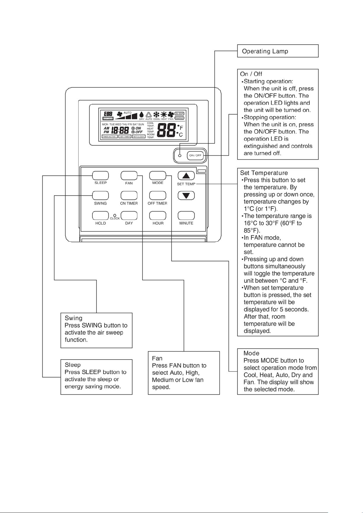
15. Clock Time Setting
• Press and hold to set the clock time.
20
Page 23
Netware3 Wired Controller
21
Page 24
222324
Page 25
Page 26
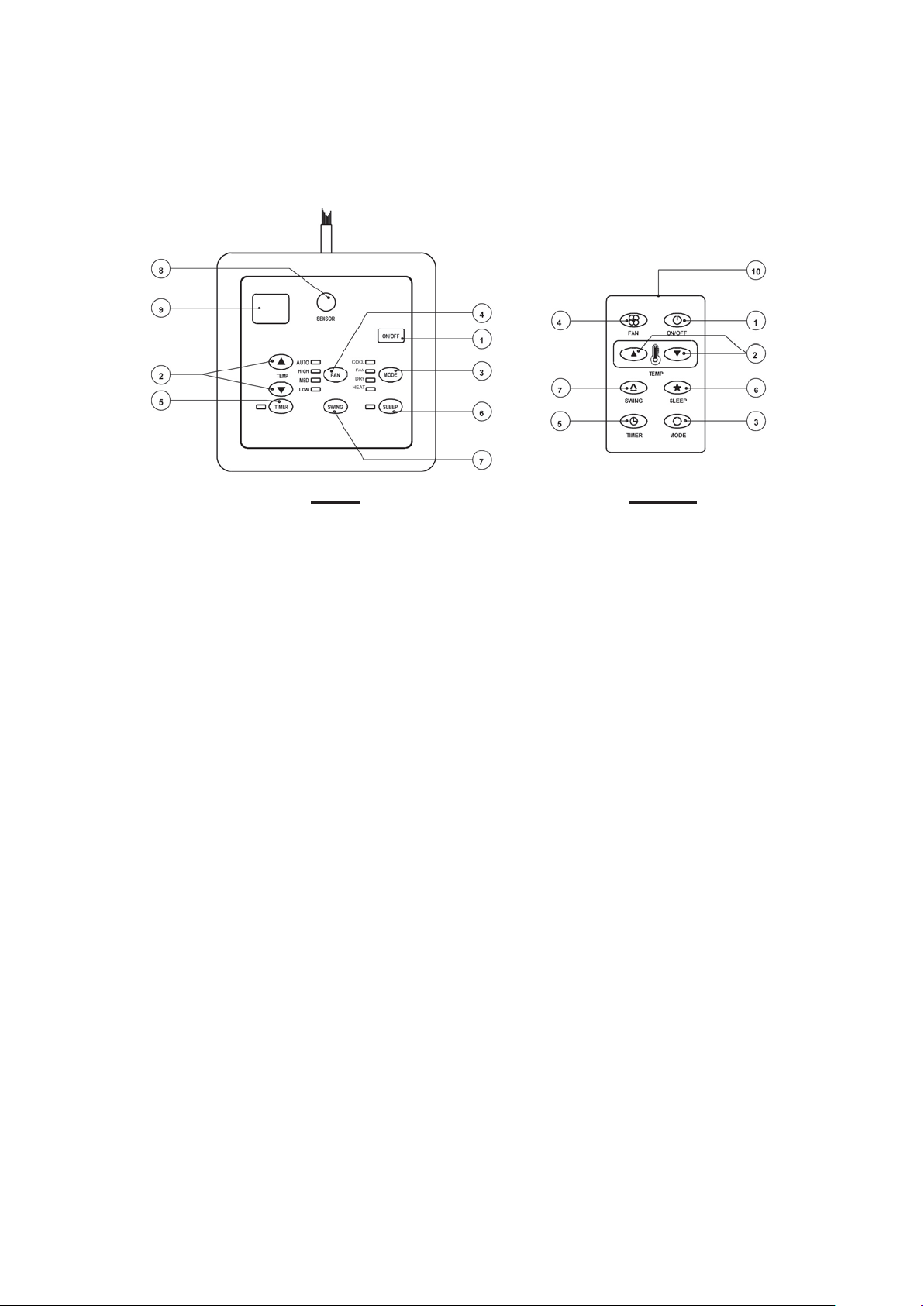
SLM3 WIRED CONTROLLER
SLM3 AC5300
1. "ON/OFF" switch
• Press to start the air conditioner unit.
• Press again to stop the unit.
2. Temperature setting
• Set the desired room temperature.
• Press button to increase or decrease the set tem-
perature. Setting range are between 16°C to 30°C
(60°F to 80°F).
3. Operation Modes
• Press the "mode" button for select the type of operating mode.
- Cooling Only :
COOL, FAN, DRY
- Heat Pump :
COOL, FAN, DRY, HEAT
4. Fan Speed selection
• Press the button until the desired fan speed is
achieved.
5. Timer
• Press the set button to select the switch timer of the
air conditioner unit (the setting range is between 1
to 15 hours).
6. "Sleep" mode
• Press button to activate the sleep function. This
function can only be activated under "cool" or
heating mode operation. When it is activated
under "cool" mode operation, the set temperature will increase 0.5°C after 30 minutes, 1°C
after 1 hour and 2°C after 2 hours. If it is activated under "HEAT" mode operation, the set
temperature will be decreased 0.5° C after 30
minutes, 1° C after 1 hour and 2° C after 2 hours.
7. Air Swing
• Press button to activate the automatic air swing
function.
8. Sensor
• Infra red sensor to receive signals from wireless
controller.
9. LED display
• To display the set temperature (in º C) and timer
delay setting (in hours).
10. Transmission source
• To transmit signals to the air conditioner.
Page 27
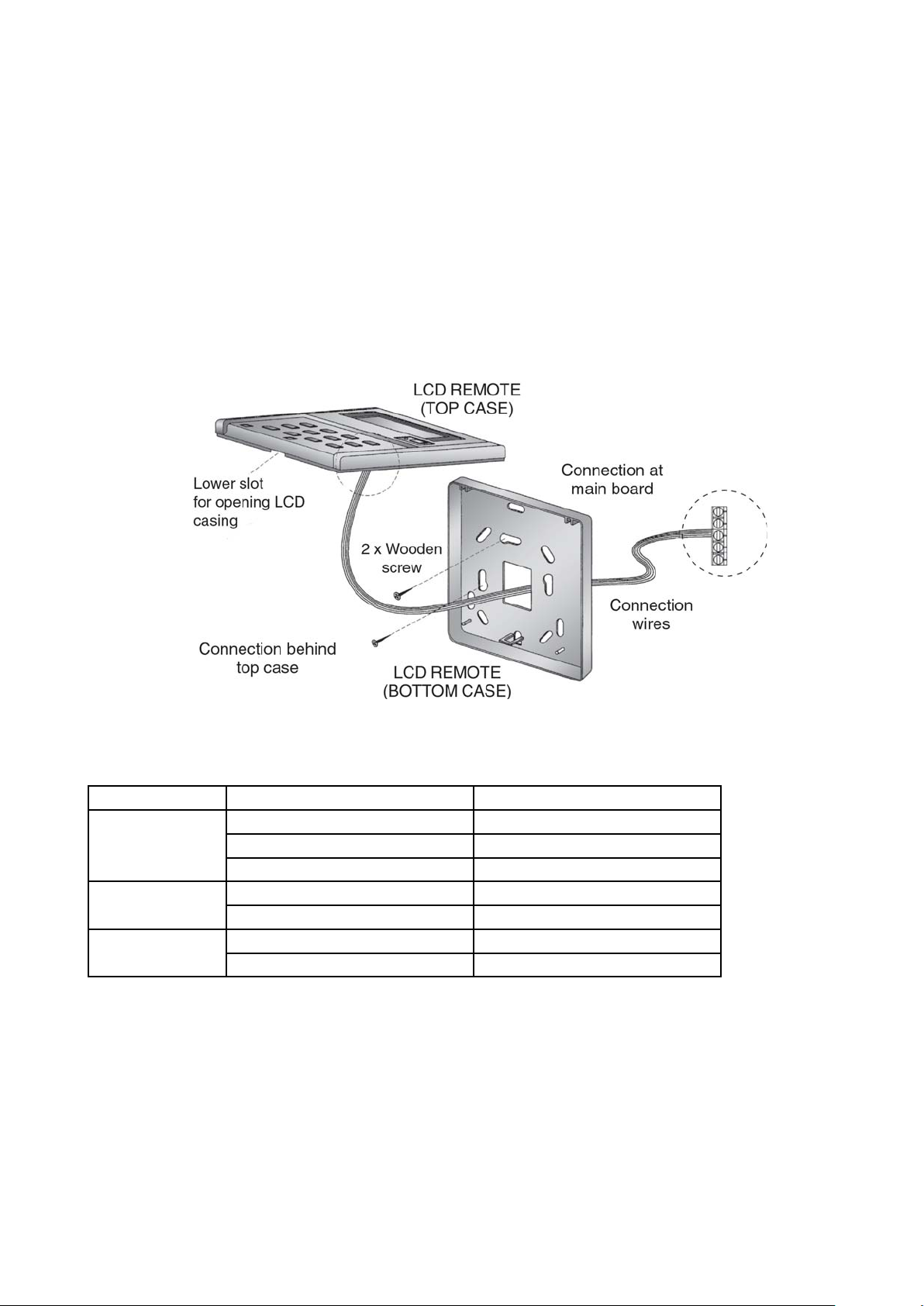
INSTALLATION OF LCD REMOTE CONTROLLER
STEP-BY-STEP GUIDE
i) First, open up the casing of the LCD remote controller into its top and bottom case using a screwdriver.
To do this, insert the screwdriver into the lower slot and slide it in the outward direction.
ii) Fix the bottom case onto the wall with the 2 wooden screws provided. Then, insert the 4 connecting
wires (from the main board) through the slot on the lower center of the case as shown below.
iii) Connect one end in each of the 3 wires to the terminal block behind the top case as illustrated.
iv) To select cooling only model or heatpump model, some adjustment required in the dip switch setting.
v) Fasten back the top and bottom case into place. Hook the two upper claws into their respective slots and
snap the lower part shut.
Dip switch setting for model selection
Pin Function Remarks
JH & JD RESERVE JH-OFF, JD-OFF
COOL, DRY, FAN JH-OFF, JD-ON
COOL, DRY, FAN, HEAT JH-ON, JD-OFF
RTC NO REAL TIME CLOCK RTC-OFF
REAL TIME CLOCK RTC-ON
NO DRY WITHOUT DRY FUNCTION NO DRY-ON
DRY FUNCTION NO DRY-OFF
25
Page 28
Sound DaSound Da
33
31
26
33
29
25
36
32
27
34
29
23
28
23
17
19
13
8
7
5
5
38
33
33
28
28
41
39
37
48
44
41
47
43
40
43
39
36
40
35
32
28
25
23
20
19
49
44
42
35
38
43
40
38
36
48
46
42
48
45
44
35
27
50
45
47
44
423942
38
33
29
25
23
48
45
43
Sound Da
Sound DaSound Da
tata
ta
tata
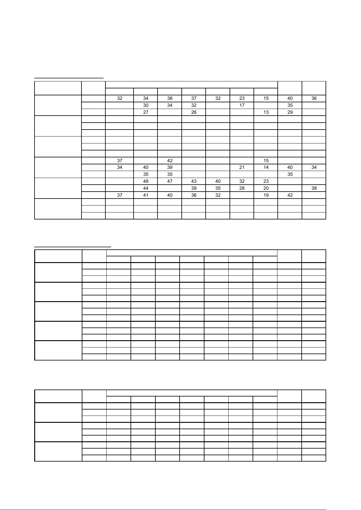
Sound Pressure Level
Wall Mounted Split Type
Model Speed
HIGH 32 34 38 37 32 23 15 40 36
MWM007G2W
MWM010G2W
MWM015G2W
MWM020G2W
MWM025G2W
MWM301W
Microphone position : MWM-G2W -- 1 m in front of the unit and 0.8 m below the vertical centre line of the unit. (JIS C 9612)
MEDIUM 27 30 34 32 26 17 14 35 31
LOW 24 27 29 26 20 13 13 29 24
HIGH 28 34 37 36 31 22 13 39 35
MEDIUM 27 30 33 31 25 17 12 34 30
LOW 24 26 28 25 19 12 11 28 23
HIGH 30 35 39 38 33 25 15 42 37
MEDIUM 28 31 34 33 26 18 13 36 32
LOW 24 26 28 26 20 13 12 29 24
HIGH 37 44 42 37 34 25 15 43 37
MEDIUM 34 40 39 34 30 21 14 40 34
LOW 30 35 35 30 26 18 13 35 30
HIGH 41 48 47 43 40 32 23 49 43
MEDIUM 39 44 43 39 35 28 20 44 38
LOW 37 41 40 36 32 25 19 42 35
HIGH 42 46 45 44 41 35 28 49 43
MEDIUM 40 45 44 43 35 33 27 47 42
LOW 37 43 43 40 35 30 26 45 39
MWM301W -- 1 m in front and 1 m below the air discharge opening of the unit (JIS B 8615)
125 Hz 250 Hz 500 Hz 1k Hz 2k Hz 4k Hz 8k Hz
1/1 Octave Sound Pressure Level (dB, ref 20μPa)
Overall
(dBA)
Noise
Criteria
Ceiling Exposed Split Type
Model
MCM020DW
MCM025DW
MCM030DW
MCM040DW
MCM050DW
Microphone position : MCM 20/25DW -- 1 m in front of the unit and 0.8 m below the air discharge opening. (JIS C 9612)
Model Speed
MCM007CBW
MCM010CBW
MCM015CBW
Microphone position : 1m in front and 0.8m below the vertical centre line of the unit.
Speed
High 45 46 47 46 41 38 29 50 45
Medium 42 43 45 42 38 34 24 47 41
Low 36 37 39 35 31 24 15 40 34
High 48 51 51 50 45 41 33 54 49
Medium 47 50 50 49 44 40 32 53 48
Low 45 47 48 47 41 36 27 50 46
High 45 48 48 47 43 33 24 51 46
Medium 44 47 47 46 42 32 23 50 45
Low 43 45 45 44 39 29 20 48 43
High 51 53 51 50 47 37 30 54 49
Medium 48 51 50 49 46 36 28 53 48
Low 46 50 49 48 44 35 27 52 47
High 51 53 51 50 47 37 30 54 49
Medium 48 51 50 49 46 36 28 53 48
Low 46 50 49 48 44 35 27 52 47
MCM 30/40/50DW -- 1 m in front of the unit and 1 m below the air discharge opening. (JIS B 8615)
High 26 34 38 42 38 35 23 45 41
Medium 23 29 36 39 34 31 18 42 38
Low 19 26 33 34 31 23 12 37 33
High 27 35 39 43 39 36 24 46 42
Medium 24 30 37 40 35 32 19 43 39
Low 20 27 34 35 32 24 13 38 34
High 28 36 40 44 40 37 25 47 43
Medium 25 31 38 41 36 33 20 44 40
Low 21 28 35 36 33 25 13 39 35
125Hz 250Hz 500Hz 1kHz 2kHz 4kHz 8kHz (dBA) Criteria
125Hz 250Hz 500Hz 1kHz 2kHz 4kHz 8kHz A (dBA) Criteria
1/1 Octave Sound pressure level (dB, ref 20μPa)
1/1 Octave Sound pressure level (dB, ref 20μPa)
Overall Noise
Overall Noise
26
Page 29
27
Ceiling Cassette Split Types
Microphone position: MCK020/025AW/AWH – 1.4m below the facia (JIS C 9612)
MCK030/040/050AW/AWH – 1.5m below the facia (JIS B 8615
Microphone position: 1.4m below the facia. (JIS C 9612)
Sound Power Level
125Hz 250Hz 500Hz 1kHz 2kHz 4kHz 8kHz
High
46 45 40 38 32 21 14 42 37
MCK020AW / AWH
Medium
44 43 37 33 28 18 12 39 32
Low
43 42 35 31 26 17 11 37 31
High
48 46 43 39 33 27 19 45 38
MCK025AW / AWH
Medium
45 43 40 35 29 21 15 42 35
Low
43 42 38 32 27 19 14 40 33
High
50 48 47 43 37 35 28 49 42
Medium
48 45 43 38 32 31 27 45 38
Low
46 43 41 35 30 30 26 43 36
High
50 49 49 46 39 38 31 51 45
MCK040AW / AWH
Medium
48 47 47 43 36 34 25 48 42
Low
46 45 46 41 34 30 23 46 41
High
54 52 51 48 43 42 34 53 47
MCK050AW / AWH
Medium
52 50 50 46 41 40 32 52 46
Low
51 49 49 45 39 39 31 50 45
Overall
(dBA)
Noise
Criteria
MCK030AW / AWH
Model
Speed
1/ 1 O cta ve So und p ressu re le ve l (dB , ref 20μP a)
125Hz 250Hz 500Hz 1kHz 2kHz 4kHz 8kHz
High
44 45 40 36 26 19 10 42 35
MCK010CW
Medium
40 38 34 28 19 9 7 35 29
Low
37 32 27 20 14 6 7 29 21
High
48 48 44 39 31 27 15 45 39
MCK015CW
Medium
42 42 36 30 22 13 7 38 31
Low
39 36 28 20 15 6 6 30 23
High
52 51 46 41 34 31 19 48 41
Medium
44 43 39 33 26 18 8 40 33
Low
41 39 35 28 22 11 7 36 30
MCK020CW
1/1 O cta ve So und p ressu re level (dB, ref 20μ Pa)
Model
Speed
Overall
(dBA)
Noise
Criteria
125Hz 250Hz 500Hz 1kHz 2kHz 4kHz 8kHz
High
53 56 49 43 35 28 21 52
MCK010CW
Medium
47 49 42 35 26 20 19 45
Low
43 44 36 27 19 14 19 39
High
52 55 53 46 41 33 24 54
MCK015CW
Medium
46 50 46 38 30 21 20 47
Low
46 48 40 30 22 12 19 41
High
56 58 55 50 42 38 29 56
Medium
50 51 48 41 32 26 20 49
Low
47 49 45 37 27 20 19 45
Model
Speed
1/1 Octave Sound Power level (dB, ref 1pW)
Overall
(dBA)
MCK020CW
Page 30

Ceiling Concealed Fan Coil Unit
Model
MCC010CW
MCC015CW
MCC020CW
MCC025CW
MCC028CW
MCC030CW
MCC038CW
MCC040CW
MCC050CW
MCC060CW
Ext. Static Overall Noise
(mmAq) 125Hz 250Hz 500Hz 1kHz 2kHz 4kHz 8kHz (dBA) Criteria
5 High333030292216103327
4 Medium 31 28 28 26 20 13 8 30 24
3 Low 28 25 24 22 16 10 7 26 20
5 High393634322718113731
4 Medium 35 34 32 29 23 14 9 34 27
3 Low 32 29 28 25 17 11 8 29 23
5 High423936342822173833
4 Medium 41 37 34 31 26 20 15 36 30
3 Low 40 36 32 29 23 18 13 34 27
5 High424137343129234033
4 Medium 41 40 36 33 29 28 22 39 32
3 Low 36 35 33 31 26 27 21 36 30
10 Super High 48 45 42 38 34 29 26 44 37
8 High454239353126224134
7 Medium 42 38 37 32 28 22 17 38 32
6 Low 36 33 33 27 23 16 11 34 27
21 Super High 54 50 46 45 40 34 30 49 44
17 High 50 45 43 42 37 31 26 46 41
13 Medium 45 40 40 38 32 26 20 42 37
9 Low 42 36 37 33 28 22 15 38 32
14 Super High 56 57 53 50 46 41 36 55 49
12 High 54 51 48 46 41 36 31 51 45
11 Medium 51 48 46 45 37 32 26 48 44
9 Low 47 45 44 41 34 28 22 45 40
21 Super High 56 49 49 46 41 37 32 51 45
18 High 54 47 47 45 39 35 29 49 44
13 Medium 49 42 43 41 35 31 24 45 40
9 Low 45 39 41 37 30 26 18 41 36
18 Super High 56 50 50 49 44 38 33 53 48
16 High 54 49 49 48 43 37 32 52 47
14 Medium 53 47 46 47 40 35 29 50 46
11 Low 51 45 44 44 36 32 26 47 43
18 Super High 57 50 51 51 46 39 35 55 50
16 High 55 49 49 50 44 37 33 53 49
14 Medium 53 46 47 47 39 34 28 50 46
10 Low 51 43 44 43 35 30 24 47 42
Speed
Microphone position : 1.4 m below the centre of the unit. (GB standard - GB/D17758 )
Tested with 2m length duct at the air discharge outlet and air return inlet.
1/1 Octave Sound pressure level (dB, ref 20μPa)
Ducted Split Fan Coil Unit
Model
125 Hz 250 Hz 500 Hz 1k Hz 2k Hz 4k Hz 8k Hz
1/1 Octave Sound Pressure Level (dB, ref 20μPa)
MDB075BW 54504644413626 49 43
MDB100BW 53544848443931 52 47
MDB125BW 53515045443829 52 46
MDB150BW 58565754524739 59 54
Microphone Position: MDB075/100/125/150BW, 1.4m below the unit (free return and the discharge air was ducted to adjacent room )
Overall
(dBA)
Noise
Criteria
28
Page 31

Selection PrSelection Pr
Selection Pr
Selection PrSelection Pr
Fan Performance Curves
ocessocess
ocess
ocessocess
FAN PERFORMANCE CURVE
MCC 010CW
29
Page 32

FAN PERFORMANCE CURVE
MCC 015CW
30
Page 33

FAN PERFORMANCE CURVE
MCC 020CW
31
Page 34

FAN PERFORMANCE CURVE
MCC 025CW
32
Page 35

FAN PERFORMANCE CURVE
MCC 028CW
33
Page 36

FAN PERFORMANCE CURVE
MCC 030CW
34
Page 37

MCC038CW Blower Performance Curve
H
M
L
Page 38

FAN PERFORMANCE CURVE
MCC 040CW
36
Page 39

FAN PERFORMANCE CURVE
MCC 050CW
37
Page 40

FAN PERFORMANCE CURVE
MCC 060CW
38
Page 41

FAN PERFORMANCE CURVE
MDB 075BW
39
Page 42

FAN PERFORMANCE CURVE
MDB 100BW
40
Page 43

FAN PERFORMANCE CURVE
MDB 125BW
41
Page 44

FAN PERFORMANCE CURVE
MDB 150BW
42
Page 45

Water Flow Vs Pressure Drop
Wall Mounted Split Type
MODELS
MWM007G2W
MWM010G2W
MWM015G2W
MWM020G2W
MWM025G2W
MWM301W
Note :
a. PRESSURE DROP CORRECTION FACTOR = 1.2947 - 0.0021 * ( EWT°C * 1.8 + 32 )
b. PRESSURE DROP CORRECTION FACTOR = 1.2947 - 0.0021 * EWT°F
LITRES/M USGPM kPa PSI
FLOW RATE WATER PRESSURE DROP
4.00 1.06 20.23 2.93
5.33 1.41 27.04 3.92
6.66 1.76 33.88 4.91
7.99 2.11 40.75 5.91
9.32 2.46 47.65 6.91
4.79 1.27 26.96 3.91
6.39 1.69 36.00 5.22
7.99 2.11 45.06 6.54
9.59 2.53 54.15 7.85
11.19 2.96 63.26 9.18
5.50 1.45 33.20 4.82
7.33 1.94 44.27 6.42
9.16 2.42 55.34 8.03
10.99 2.90 66.41 9.63
12.82 3.39 77.47 11.24
7.79 2.06 17.71 2.57
10.38 2.74 24.09 3.49
12.98 3.43 30.71 4.45
15.58 4.11 37.56 5.45
18.17 4.80 44.65 6.48
9.08 2.40 19.88 2.88
12.11 3.20 26.91 3.90
15.14 4.00 34.13 4.95
18.17 4.80 41.56 6.03
21.20 5.60 49.20 7.14
11.13 2.94 26.21 3.80
14.84 3.92 34.90 5.06
18.55 4.90 43.66 6.33
22.26 5.88 52.51 7.62
25.97 6.86 61.44 8.91
43
Page 46

Water Flow Vs Pressure Drop
Ceiling Exposed Split Type
MODELS
MCM020DW
MCM025DW
MCM030DW
MCM040DW
MCM050DW
Note :
a. PRESSURE DROP CORRECTION FACTOR = 1.2947 - 0.0021 * ( EWT°C * 1.8 + 32 )
b. PRESSURE DROP CORRECTION FACTOR = 1.2947 - 0.0021 * EWT°F
LITRES/M USGPM kPa PSI
FLOW RATE WATER PRESSURE DROP
8.90 2.35 23.37 3.39
11.87 3.14 30.36 4.40
14.84 3.92 37.73 5.47
17.81 4.70 45.48 6.60
20.78 5.49 53.62 7.78
10.49 2.77 26.38 3.83
13.99 3.70 36.14 5.24
17.49 4.62 46.37 6.73
20.99 5.54 57.08 8.28
24.49 6.47 68.27 9.90
12.40 3.28 22.04 3.20
16.54 4.37 31.14 4.52
20.67 5.46 41.12 5.96
24.80 6.55 51.97 7.54
28.94 7.64 63.69 9.24
15.70 4.15 11.21 1.63
20.93 5.53 15.45 2.24
26.16 6.91 19.94 2.89
31.39 8.29 24.68 3.58
36.62 9.68 29.67 4.30
22.69 5.99 17.70 2.57
30.26 7.99 24.35 3.53
37.82 9.99 31.38 4.55
45.38 11.99 38.79 5.63
52.95 13.99 46.58 6.76
44
Page 47

Water Flow Vs Pressure Drop
Ceiling Exposed Split Type
MODELS
MCM007CBW
MCM010CBW
MCM015CBW
MCM015EW
MCM020EW
MCM025EW
LITRES/M USGPM kPa PSI
FLOW RATE WATER PRESSURE DROP
3.29 0.87 4.21 0.61
4.39 1.16 5.94 0.86
5.49 1.45 7.84 1.14
6.59 1.74 9.90 1.44
7.69 2.03 12.12 1.76
4.29 1.13 6.84 0.99
5.72 1.51 10.20 1.48
7.15 1.89 13.71 1.99
8.58 2.27 17.38 2.52
10.01 2.64 21.21 3.08
5.29 1.40 1.77 0.26
7.06 1.86 2.84 0.41
8.82 2.33 4.08 0.59
10.58 2.80 5.48 0.80
12.35 3.26 7.06 1.02
7.79 2.06 11.73 1.70
10.38 2.74 16.90 2.45
12.98 3.43 22.70 3.29
15.58 4.11 29.13 4.22
18.17 4.80 36.19 5.25
10.20 2.69 23.78 3.45
13.60 3.59 31.82 4.62
17.00 4.49 39.92 5.79
20.40 5.39 48.09 6.97
23.80 6.29 56.31 8.17
10.61 2.80 27.78 4.03
14.14 3.74 37.56 5.45
17.68 4.67 47.59 6.90
21.22 5.60 57.87 8.39
24.75 6.54 68.41 9.92
Note :
a. PRESSURE DROP CORRECTION FACTOR = 1.2947 - 0.0021 * ( EWT°C * 1.8 + 32 )
b. PRESSURE DROP CORRECTION FACTOR = 1.2947 - 0.0021 * EWT°F
45
Page 48

Water Flow Vs Pressure Drop
Ceiling Cassette Split Type
MODELS
MCK020AW
MCK025AW
MCK030AW
MCK040AW
MCK050AW
Note :
a. PRESSURE DROP CORRECTION FACTOR = 1.2947 - 0.0021 * ( EWT°C * 1.8 + 32 )
b. PRESSURE DROP CORRECTION FACTOR = 1.2947 - 0.0021 * EWT°F
LITRES/M USGPM kPa PSI
FLOW RATE WATER PRESSURE DROP
11.40 3.01 8.80 1.28
15.20 4.02 14.19 2.06
19.00 5.02 20.60 2.99
22.80 6.02 27.99 4.06
26.60 7.03 36.30 5.26
12.90 3.41 10.91 1.58
17.20 4.54 17.61 2.55
21.50 5.68 25.60 3.71
25.80 6.82 34.81 5.05
30.10 7.95 45.15 6.55
15.14 4.00 18.53 2.69
20.18 5.33 28.86 4.19
25.23 6.67 39.90 5.79
30.28 8.00 51.65 7.49
35.32 9.33 64.11 9.30
17.11 4.52 22.97 3.33
22.82 6.03 35.27 5.11
28.52 7.53 48.49 7.03
34.22 9.04 62.63 9.08
39.93 10.55 77.70 11.27
18.58 4.91 30.11 4.37
24.78 6.55 45.92 6.66
30.97 8.18 63.00 9.14
37.16 9.82 81.35 11.80
43.36 11.45 100.98 14.65
46
Page 49

Water Flow Vs Pressure Drop
Ceiling Cassette Split Type
LITRES/M USGPM kPa PSI
5.83 1.54
11.61 1.68
6.67 1.76
14.86 2.15
7.67 2.03
19.28 2.80
8.33 2.20
22.54 3.27
9.17 2.42
26.98 3.91
10.00 2.64 16.38
2.38
10.83 2.86 19.03
2.76
11.67 3.08 21.89
3.18
13.00 3.43 26.88
3.90
14.17 3.74 31.66
4.59
10.83 2.86
19.01
2.76
12.50 3.30
24.91
3.61
13.33 3.52
28.17
4.09
13.50 3.57
28.84
4.18
14.67 3.87
33.78
4.90
9.07 2.40
2.08 0.30
12.10 3.20
2.61 0.52
15.12 3.99
5.55 0.80
18.14 4.79
7.88 1.14
21.17 5.59
10.60 1.54
9.45 2.50 2.22
0.32
12.60 3.33 3.85
0.56
15.75 4.16 5.91
0.86
18.90 4.99 8.40
1.22
22.05 5.82 5.91
1.64
10.76 2.84
2.99
0.43
14.34 3.79
5.25
0.76
17.93 4.74
7.96
1.15
21.52 5.68
11.12
1.61
25.10 6.63
14.75
2.14
11.59 3.06
3.47 0.50
15.46 4.08
6.04 0.88
19.32 5.10
9.13 1.32
23.18 6.12
12.75 1.85
27.05 7.15
16.90 2.45
11.84 3.13
3.60 0.52
15.78 4.17
6.21 0.90
19.73 5.21
9.35 1.36
23.68 6.25
13.03 1.89
27.62 7.30
17.25 2.50
MCK050AWH
MCK020AWH
MCK025AWH
MCK030AWH
MCK040AWH
MODELS
FLOW RATE
WATER PRESSURE DROP
MCK010CW
MCK015CW
MCK020CW
Revised Table
Page 50

Water Flow Vs Pressure Drop
Ceiling Concealed Split Type
MODELS
MCC010CW
MCC015CW
MCC020CW
MCC025CW
MCC028CW
MCC030CW
MCC038CW
MCC040CW
MCC050CW
MCC060CW
LITRES/M USGPM kPa PSI
Note :
a. PRESSURE DROP CORRECTION FACTOR = 1.2947 - 0.0021 * ( EWT°C * 1.8 + 32 )
b. PRESSURE DROP CORRECTION FACTOR = 1.2947 - 0.0021 * EWT°F
FLOW RATE WATER PRESSURE DROP
5.00 1.32 5.23 0.76
6.66 1.76 7.00 1.02
8.33 2.20 8.79 1.28
10.00 2.64 10.60 1.54
11.66 3.08 12.42 1.80
5.79 1.53 11.82 1.71
7.72 2.04 15.79 2.29
9.65 2.55 19.76 2.87
11.58 3.06 23.75 3.44
13.51 3.57 27.74 4.02
9.08 2.40 9.50 1.38
12.11 3.20 13.04 1.89
15.14 4.00 16.78 2.43
18.17 4.80 20.71 3.00
21.20 5.60 24.83 3.60
11.31 2.99 15.62 2.26
15.08 3.98 21.17 3.07
18.85 4.98 26.89 3.90
22.62 5.98 32.78 4.75
26.39 6.97 38.85 5.63
13.10 3.46 11.94 1.73
17.47 4.62 15.99 2.32
21.84 5.77 20.09 2.91
26.21 6.92 24.22 3.51
30.58 8.08 28.39 4.12
17.81 4.70 23.26 3.37
23.74 6.27 31.87 4.62
29.68 7.84 40.91 5.93
35.62 9.41 50.37 7.31
41.55 10.98 60.27 8.74
14.11 3.73 6.71 0.97
18.81 4.97 9.31 1.35
23.51 6.21 12.10 1.76
28.21 7.45 15.08 2.19
32.91 8.69 18.23 2.64
19.19 5.07 11.16 1.62
25.59 6.76 14.04 2.04
31.99 8.45 17.23 2.50
38.39 10.14 20.71 3.00
44.79 11.83 24.49 3.55
23.62 6.24 19.53 2.83
31.50 8.32 26.56 3.85
39.37 10.40 33.85 4.91
47.24 12.48 41.41 6.01
55.12 14.56 49.23 7.14
27.21 7.19 3.54 0.51
36.28 9.58 4.88 0.71
45.35 11.98 6.32 0.92
54.42 14.38 7.83 1.14
63.49 16.77 9.43 1.37
48
Page 51

Water Flow Vs Pressure Drop
Ducted Split Type
MODELS
MDB075BW
MDB100BW
MDB125BW
MDB150BW
LITRES/M USGPM kPa PSI
FLOW RATE WATER PRESSURE DROP
38.11 10.07 22.00 3.19
50.82 13.42 27.65 4.01
63.52 16.78 33.37 4.84
76.22 20.14 39.16 5.68
88.93 23.49 45.01 6.53
47.90 12.65 24.69 3.58
63.86 16.87 29.58 4.29
79.83 21.09 34.87 5.06
95.80 25.31 40.56 5.88
111.76 29.52 46.64 6.76
63.01 16.64 28.03 4.07
84.01 22.19 34.14 4.95
105.01 27.74 40.69 5.90
126.01 33.29 47.67 6.91
147.01 38.84 55.09 7.99
75.61 19.97 31.97 4.64
100.82 26.63 38.04 5.52
126.02 33.29 44.59 6.47
151.22 39.95 51.62 7.49
176.43 46.61 59.12 8.58
Note :
a. PRESSURE DROP CORRECTION FACTOR = 1.2947 - 0.0021 * ( EWT°C * 1.8 + 32 )
b. PRESSURE DROP CORRECTION FACTOR = 1.2947 - 0.0021 * EWT°F
49
Page 52

Correction Factors
Air Flow Correction Factors
MWM007G2W Low 0.74 0.90
MWM007G2W Medium 0.87 0.95
MWM007G2W High 1.00 1.00
MWM010G2W Low 0.79 0.92
MWM010G2W Medium 0.90 0.96
MWM010G2W High 1.00 1.00
MWM015G2W Low 0.74 0.78
MWM015G2W Medium 0.87 0.85
MWM015G2W High 1.00 1.00
MWM020G2W Low 0.82 0.92
MWM020G2W Medium 0.93 0.97
MWM020G2W High 1.00 1.00
MWM025G2W Low 0.79 0.87
MWM025G2W Medium 0.91 0.95
MWM025G2W High 1.00 1.00
MCM007CBW Low 0.85 0.85
MCM007CBW Medium 0.94 0.94
MCM007CBW High 1.00 1.00
MCM010CBW Low 0.85 0.85
MCM010CBW Medium 0.94 0.93
MCM010CBW High 1.00 1.00
MCM015CBW Low 0.77 0.77
MCM015CBW Medium 0.82 0.82
MCM015CBW High 1.00 1.00
MCM020DW Low 0.80 0.85
MCM020DW Medium 0.95 0.98
MCM020DW High 1.00 1.00
MCM025DW Low 0.80 0.85
MCM025DW Medium 0.95 0.98
MCM025DW High 1.00 1.00
MCM030DW Low 0.94 0.94
MCM030DW Medium 0.96 0.97
MCM030DW High 1.00 1.00
MCM040DW Low 0.93 0.95
MCM040DW Medium 0.96 0.96
MCM040DW High 1.00 1.00
MCM050DW Low 0.93 0.94
MCM050DW Medium 0.98 0.98
MCM050DW High 1.00 1.00
50
Page 53

Model Speed Air Flow Ratio (Sensible Capacity) Air Flow Ratio (Total Capacity)
0.75
0.88
0.64
0.83
0.72
0.83
0.74
0.84
0.68
0.86
0.76
0.88
MCM015EW Low 0.78 0.87
MCM015EW Medium 0.85 0.92
MCM015EW High 1.00 1.00
MCM020EW Low 0.85 0.90
MCM020EW Medium 0.89 0.94
MCM020EW High 1.00 1.00
MCM025EW Low 0.83 0.89
MCM025EW Medium 0.90 0.95
MCM025EW High 1.00 1.00
MCK020AW Low 0.74 0.77
MCK020AW Medium 0.90 0.91
MCK020AW High 1.00 1.00
MCK025AW Low 0.74 0.75
MCK025AW Medium 0.91 0.90
MCK025AW High 1.00 1.00
MCK030AW Low 0.72 0.75
MCK030AW Medium 0.88 0.89
MCK030AW High 1.00 1.00
MCK040AW Low 0.72 0.75
MCK040AW Medium 0.93 0.92
MCK040AW High 1.00 1.00
MCK050AW Low 0.78 0.80
MCK050AW Medium 0.95 0.94
MCK050AW High 1.00 1.00
MCK020WH Low 0.91 0.95
MCK020WH Medium 0.93 0.97
MCK020WH High 1.00 1.00
MCK025WH Low 0.89 0.94
MCK025WH Medium 0.93 0.96
MCK025WH High 1.00 1.00
MCK030WH Low 0.88 0.93
MCK030WH Medium 0.92 0.95
MCK030WH High 1.00 1.00
MCK040WH Low 0.88 0.92
MCK040WH Medium 0.93 0.96
MCK040WH High 1.00 1.00
MCK050WH Low 0.81 0.92
MCK050WH Medium 0.93 0.96
MCK050WH High 1.00 1.00
MCK010CW Low 0.89 0.87
MCK010CW Medium 0.95 0.93
MCK010CW High 1.00 1.00
MCK015CW Low 0.88 0.89
MCK015CW Medium 0.94 0.93
MCK015CW High 1.00 1.00
MCK020CW Low 0.90 0.93
MCK020CW Medium 0.96 0.96
MCK020CW High 1.00 1.00
51
Page 54

Model Speed Air Flow Ratio (Sensible Capacity) Air Flow Ratio (Total Capacity)
MCC010CW Low 0.82 0.82
MCC010CW Medium 0.92 0.92
MCC010CW High 1.00 1.00
MCC015CW Low 0.75 0.75
MCC015CW Medium 0.91 0.91
MCC015CW High 1.00 1.00
MCC020CW Low 0.93 0.93
MCC020CW Medium 0.98 0.98
MCC020CW High 1.00 1.00
MCC025CW Low 0.88 0.80
MCC025CW Medium 0.98 0.91
MCC025CW High 1.00 1.00
MCC028CW Low 0.86 0.86
MCC028CW Medium 0.94 0.95
MCC028CW High 1.00 1.00
MCC030CW Low 0.86 0.86
MCC030CW Medium 0.94 0.95
MCC030CW High 1.00 1.00
MCC038CW Low 0.74 0.74
MCC038CW Medium 0.98 0.79
MCC038CW High 1.00 1.00
MCC040CW Low 0.74 0.74
MCC040CW Medium 0.98 0.79
MCC040CW High 1.00 1.00
MCC050CW Low 0.88 0.88
MCC050CW Medium 0.95 0.95
MCC050CW High 1.00 1.00
MCC060CW Low 0.84 0.84
MCC060CW Medium 0.95 0.95
MCC060CW High 1.00 1.00
MDB075BW High 1.00 1.00
MDB100BW High 1.00 1.00
MDB125BW High 1.00 1.00
MDB150BW High 1.00 1.00
52
Page 55

Altitude Correction Factors
Elevation, m Total Capacity Sensible Capacity
0 1.00 1.00
300 0.99 0.96
600 0.98 0.93
900 0.97 0.90
1200 0.96 0.86
1500 0.94 0.83
1800 0.93 0.80
Heating Capacity Correction Factors
MCK020AWH - MCK050AWH
EAT
°C 37.8 43.3 45 48.8 50 54.4 60 65.5 70
4.4
7.2
10
12.7
15.5
18.3
20
21.1
22
23.9
26.7
1.112 1.143 1.153 1.175 1.182 1.207 1.239 1.271 1.296
1.044 1.078 1.088 1.112 1.119 1.146 1.181 1.214 1.244
0.977 1.014 1.026 1.051 1.060 1.089 1.127 1.164 1.191
0.908 0.947 0.959 0.986 0.995 1.026 1.066 1.106 1.138
0.839 0.882 0.895 0.924 0.934 0.968 1.011 1.053 1.085
0.796 0.830 0.841 0.868 0.876 0.910 0.955 0.996 1.032
0.729 0.775 0.790 0.822 0.831 0.869 0.917 0.963 1.000
0.685 0.740 0.756 0.792 0.802 0.843 0.892 0.942 0.979
0.680 0.729 0.743 0.777 0.786 0.826 0.876 0.924 0.962
0.630 0.681 0.697 0.732 0.743 0.783 0.835 0.886 0.927
0.562 0.616 0.632 0.669 0.681 0.724 0.778 0.832 0.874
ENT TEMP, °C
MCK020AW
EAT
°C 37.8 43.3 45 48.8 50 54.4 60 65.5 70
4.4
7.2
10
12.7
15.5
18.3
20
21.1
22
23.9
26.7
1.256 1.343 1.370 1.431 1.450 1.520 1.609 1.696 1.770
1.175 1.265 1.293 1.355 1.374 1.446 1.537 1.627 1.699
1.087 1.179 1.207 1.271 1.291 1.364 1.458 1.550 1.627
1.004 1.142 1.127 1.192 1.213 1.288 1.384 1.478 1.555
0.917 1.014 1.044 1.110 1.132 1.209 1.308 1.404 1.483
0.849 0.939 0.968 1.033 1.054 1.131 1.232 1.328 1.410
0.777 0.877 0.909 0.978 1.000 1.081 1.183 1.284 1.366
0.730 0.837 0.870 0.943 0.965 1.048 1.151 1.255 1.338
0.716 0.822 0.850 0.920 0.943 1.024 1.129 1.231 1.314
0.657 0.761 0.793 0.865 0.887 0.970 1.076 1.180 1.266
0.572 0.678 0.711 0.784 0.807 0.892 1.000 1.106 1.194
ENT TEMP, °C
MCK025AW
EAT
°C 37.8 43.3 45 48.8 50 54.4 60 65.5 70
4.4
7.2
10
12.7
15.5
18.3
20
21.1
22
23.9
26.7
1.311 1.366 1.383 1.421 1.433 1.477 1.533 1.588 1.633
1.231 1.289 1.307 1.347 1.359 1.406 1.464 1.522 1.567
1.145 1.205 1.224 1.266 1.279 1.327 1.389 1.449 1.501
1.062 1.126 1.145 1.189 1.203 1.253 1.318 1.381 1.434
0.977 1.044 1.064 1.110 1.125 1.178 1.246 1.312 1.368
0.920 0.977 0.997 1.040 1.054 1.107 1.177 1.243 1.300
0.842 0.913 0.935 0.985 1.000 1.057 1.130 1.202 1.2599
0.791 0.871 0.895 0.949 0.965 1.025 1.100 1.175 1.234
0.782 0.855 0.878 0.929 0.944 1.003 1.078 1.152 1.212
0.725 0.801 0.824 0.877 0.893 0.954 1.031 1.107 1.167
0.641 0.720 0.744 0.798 0.816 0.878 0.959 1.037 1.101
ENT TEMP, °C
53
Page 56

MCK030AW
EAT
°C 37.8 43.3 45 48.8 50 54.4 60 65.5 70
4.4
7.2
10
12.7
15.5
18.3
20
21.1
22
23.9
26.7
1.344 1.380 1.390 1.415 1.422 1.451 1.486 1.522 1.550
1.263 1.301 1.312 1.339 1.347 1.377 1.416 1.454 1.488
1.182 1.224 1.237 1.266 1.275 1.308 1.351 1.393 1.424
1.098 1.143 1.156 1.187 1.197 1.233 1.278 1.322 1.361
1.015 1.064 1.079 1.112 1.123 1.161 1.211 1.259 1.298
0.962 1.000 1.014 1.044 1.054 1.092 1.143 1.191 1.234
0.880 0.934 0.951 0.988 1.000 1.043 1.098 1.152 1.196
0.828 0.892 0.911 0.952 0.965 1.012 1.069 1.126 1.171
0.822 0.878 0.895 0.934 0.946 0.991 1.048 1.104 1.151
0.766 0.825 0.843 0.884 0.897 0.944 1.004 1.063 1.108
0.685 0.747 0.766 0.809 0.823 0.872 0.936 0.998 1.045
ENT TEMP, °C
MCK040AW
EAT
°C 37.8 43.3 45 48.8 50 54.4 60 65.5 70
4.4
7.2
10
12.7
15.5
18.3
20
21.1
22
23.9
26.7
1.330 1.373 1.386 1.416 1.425 1.459 1.503 1.546 1.580
1.249 1.295 1.309 1.340 1.350 1.387 1.433 1.479 1.517
1.165 1.214 1.229 1.263 1.274 1.313 1.363 1.412 1.452
1.086 1.138 1.154 1.190 1.202 1.244 1.297 1.349 1.388
1.000 1.055 1.073 1.111 1.123 1.168 1.224 1.280 1.324
0.948 0.993 1.008 1.043 1.054 1.099 1.157 1.212 1.258
0.867 0.928 0.946 0.988 1.000 1.050 1.111 1.172 1.2195
0.815 0.885 0.906 0.952 0.965 1.018 1.081 1.146 1.194
0.809 0.871 0.890 0.934 0.946 0.997 1.061 1.124 1.173
0.749 0.815 0.835 0.880 0.894 0.947 1.013 1.079 1.130
0.668 0.737 0.758 0.806 0.821 0.876 0.946 1.014 1.066
ENT TEMP, °C
MCK050AW
EAT
°C 37.8 43.3 45 48.8 50 54.4 60 65.5 70
4.4
7.2
10
12.7
15.5
18.3
20
21.1
22
23.9
26.7
1.321 1.370 1.385 1.419 1.430 1.469 1.519 1.568 1.607
1.241 1.293 1.309 1.344 1.356 1.397 1.450 1.501 1.542
1.158 1.213 1.230 1.268 1.280 1.324 1.380 1.435 1.477
1.075 1.132 1.150 1.190 1.203 1.249 1.308 1.366 1.411
0.989 1.050 1.069 1.111 1.125 1.173 1.236 1.297 1.346
0.933 0.985 1.002 1.041 1.054 1.103 1.167 1.227 1.279
0.854 0.920 0.941 0.986 1.000 1.053 1.121 1.187 1.2398
0.803 0.878 0.900 0.950 0.965 1.021 1.091 1.160 1.214
0.795 0.863 0.884 0.931 0.945 1.000 1.070 1.138 1.193
0.736 0.806 0.828 0.877 0.892 0.948 1.020 1.090 1.149
0.655 0.729 0.752 0.803 0.819 0.878 0.953 1.026 1.084
ENT TEMP, °C
All other models
EAT
°C 37.8 43.3 45 48.8 50 54.4 60 65.5 70
4.4
7.2
10
12.7
15.5
18.3
20
21.1
22
23.9
26.7
1.338 1.376 1.388 1.414 1.422 1.452 1.491 1.529 1.559
1.257 1.297 1.310 1.338 1.347 1.379 1.421 1.462 1.497
1.176 1.221 1.235 1.265 1.275 1.311 1.356 1.401 1.433
1.093 1.140 1.155 1.187 1.198 1.235 1.284 1.331 1.370
1.010 1.061 1.077 1.113 1.124 1.165 1.217 1.268 1.306
0.958 0.999 1.013 1.044 1.054 1.095 1.149 1.199 1.242
0.877 0.933 0.950 0.989 1.000 1.046 1.103 1.159 1.2035
0.824 0.890 0.910 0.953 0.965 1.014 1.074 1.134 1.179
0.819 0.877 0.895 0.935 0.947 0.994 1.054 1.112 1.158
0.758 0.819 0.838 0.880 0.894 0.943 1.005 1.066 1.115
0.677 0.741 0.761 0.806 0.820 0.871 0.937 1.001 1.052
ENT TEMP, °C
54
Page 57

Engineering and PhEngineering and Ph
Engineering and Ph
Engineering and PhEngineering and Ph
ysical Daysical Da
ysical Da
ysical Daysical Da
tata
ta
tata
General Data - MWM-G2W
MODEL
NOMINAL TOTAL COOLING CAPACITY
NOMINAL SENSIBLE COOLING CAPACITY
NOMINAL TOTAL HEATING CAPACITY (ENTERING
WATER TEMP. = 50°C)
HIGH l/s / CFM 130 / 275 142 / 300
NOMINAL AIR FLOW
UNIT DIMENSION
PACKING DIMENSION
UNIT WEIGHT
SOUND PRESSURE LEVEL ( H/M/L )
NOMINAL WATER FLOW RATE
HEAD LOSS (COOLING)
HEAD LOSS (HEATING) : 50°C
MAX. WORKING PRESSURE
SURFACE AIR VELOCITY
CONNECTION
CONTROL
CONDENSATE DRAIN SIZE
1) ALL SPECIFICATIONS ARE SUBJECTED TO CHANGE BY THE MANUFACTURER WITHOUT PRIOR NOTICE.
2) ALL UNITS ARE BEING TESTED AND COMPLY TO ISO 5151 & ISO13253.
3) NOMINAL COOLING AND HEATING CAPACITY ARE BASED ON THE CONDITIONS BELOW :
a) COOLING - ENTERING AIR TEMP. : 27°C (80.6°F) DB / 19°C (66.2°F) WB, ENTERING WATER TEMP. : 7°C (44.6°F), LEAVING WATER TEMP. : 12°C (53.6°F)
b) HEATING - ENTERING AIR TEMP.: 20°C (68°F) DB, ENTERING WATER TEMP. : 50°C (122°F), WATER FLOW RATE BASED ON COOLING CYCLE.
4) SOUND PRESSURE LEVEL ARE ACCORDING TO JIS C 9612 STANDARD. POSITION OF THE MEASUREMENT POINT IS 1m IN FRONT AND
0.8m BELOW THE VERTICAL CENTRE LINE OF THE UNIT.
MEDIUM l/s / CFM
LOW l/s / CFM 83 / 17 5 94 / 200
HEIGHT mm/in 260 / 10.2 260 / 10.2
WIDTH mm/in
DEPTH mm/in 198 / 7.8 198 / 7.8
HEIGHT mm/in 330 / 13.0 330 / 13.0
WIDTH mm/in
DEPTH mm/in 265 / 10.4 265 / 10.4
ROOM TEMPERATURE
AIR DISCHARGE
OPERATION
Btu/h 8000 9500
W 2340 2780
Btu/h 5900 6900
W 1730 2030
Btu/h 10300 12800
W 3020 3750
kg/lb 10 / 22.1 12 / 26.5
dBA
USGPM 1.76 2.11
LITRES/M
kPa / psi 48 / 7 65 / 9.4
kPa / psi 42 / 6.1 59 / 8.5
kPa / psi
m/s 0.65 0.61
ft/min 127.8 121.0
mm/in
MWM07G2W MWM10G2W
106 / 225 118 / 250
799 / 31.5 899 / 35.4
827 / 32.6 827 / 32.6
38 / 33 / 28 39 / 34 / 28
6.66 7.99
1608 / 233
1/2" BSP FEMALE ADAPTOR
MICRO-COMPUTER CONTROLLED THERMOSTAT
AUTOMATIC LOUVER (UP& DOWN)
LCD WIRELESS MICRO-COMPUTER REMOTE CONTROL
12.7 / 0.5
55
Page 58

General Data - MWM-G2W
MODEL
NOMINAL TOTAL COOLING CAPACITY
NOMINAL SENSIBLE COOLING CAPACITY
NOMINAL TOTAL HEATING CAPACITY (ENTERING
WATER TEMP. = 50°C)
Btu/h 11000 15500
W 3220 4540
Btu/h 8010 12480
W 2350 3650
Btu/h 14000 20500
W 4100 6010
HIGH l/s / CFM 163 / 345 297 / 630
NOMINAL AIR FLOW
MEDIUM l/s / CFM
LOW l/s / CFM 104 / 220 208 / 440
HEIGHT mm/in 260 / 10.2 304 / 12.0
UNIT DIMENSION
WIDTH mm/in
DEPTH mm/in 198 / 7.8 222 / 8.7
HEIGHT mm/in 330 / 13.0 378 / 14.9
PACKING DIMENSION
WIDTH mm/in
DEPTH mm/in 265 / 10.4 292 / 11.5
UNIT WEIGHT
SOUND PRESSURE LEVEL ( H/M/L )
NOMINAL WATER FLOW RATE
HEAD LOSS (COOLING)
HEAD LOSS (HEATING) : 50°C
MAX. WORKING PRESSURE
SURFACE AIR VELOCITY
kg/lb 12 / 26.5 16 / 35.3
dBA
USGPM 2.42 3.43
LITRES/M
kPa / psi 77 / 11.1 50 / 7.3
kPa / psi 64 / 9.2 51 / 7.3
kPa / psi
m/s 0.71 0.90
ft/min 139.1 177.4
CONNECTION
ROOM TEMPERATURE
CONTROL
AIR DISCHARGE
OPERATION
CONDENSATE DRAIN SIZE
1) ALL SPECIFICATIONS ARE SUBJECTED TO CHANGE BY THE MANUFACTURER WITHOUT PRIOR NOTICE.
2) ALL UNITS ARE BEING TESTED AND COMPLY TO ISO 5151 & ISO13253.
3) NOMINAL COOLING AND HEATING CAPACITY ARE BASED ON THE CONDITIONS BELOW :
a) COOLING - ENTERING AIR TEMP. : 27°C (80.6°F) DB / 19°C (66.2°F) WB, ENTERING WATER TEMP. : 7°C (44.6°F), LEAVING WATER TEMP. : 12°C (53.6°F)
b) HEATING - ENTERING AIR TEMP.: 20°C (68°F) DB, ENTERING WATER TEMP. : 50°C (122°F), WATER FLOW RATE BASED ON COOLING CYCLE.
4) SOUND PRESSURE LEVEL ARE ACCORDING TO JIS C 9612 STANDARD. POSITION OF THE MEASUREMENT POINT IS 1m IN FRONT AND
0.8m BELOW THE VERTICAL CENTRE LINE OF THE UNIT.
mm/in 12.7 / 0.5 19.05 / 0.75
MWM15G2W MWM20G2W
134 / 285 231 / 490
899 / 35.4 1062 / 41.8
827 / 32.6 1100 / 43.3
42 / 36 / 29 49 / 44 / 42
9.16 12.98
1608 / 233
1/2" BSP FEMALE ADAPTOR
MICRO-COMPUTER CONTROLLED THERMOSTAT
AUTOMATIC LOUVER (UP& DOWN)
LCD WIRELESS MICRO-COMPUTER REMOTE CONTROL
56
Page 59

General Data - MWM301W
360 / 14.2
1200 / 47.2
200 / 7.9
MODEL
NOMINAL TOTAL COOLING CAPACITY
NOMINAL SENSIBLE COOLING CAPACITY
NOMINAL TOTAL HEATING CAPACITY (ENTERING
WATER TEMP. = 50°C)
Btu/h
W 5280 6450
Btu/h 14750 16720
W
Btu/h 23000 23000
W 6740 6740
HIGH l/s / CFM
NOMINAL AIR FLOW
MEDIUM l/s / CFM 274 / 580 297 / 630
LOW l/s / CFM 222 / 470 236 / 500
HEIGHT mm/in
UNIT DIMENSION
WIDTH mm/in 1062 / 41.8 815 / 32.1
DEPTH mm/in 222 / 8.7 181 / 7.1
HEIGHT mm/in
PACKING DIMENSION
WIDTH mm/in 1100 / 43.3 1100 / 43.3
DEPTH mm/in 292 / 11.5 301 / 11.9
UNIT WEIGHT
SOUND PRESSURE LEVEL ( H/M/L )
NOMINAL WATER FLOW RATE
HEAD LOSS (COOLING)
HEAD LOSS (HEATING) : 50°C
MAX. WORKING PRESSURE
SURFACE AIR VELOCITY
kg/lb
dBA 50 / 48 / 45 49 / 47 / 45
USGPM 4.00 4.90
LITRES/M
kPa / psi 69 / 10 52 / 7.6
kPa / psi 71 / 10.2 19 / 2.7
kPa / psi
m/s 0.94 1.09
ft/min
CONNECTION 1/2" BSP FEMALE ADAPTOR
ROOM TEMPERATURE
CONTROL
AIR DISCHARGE
OPERATION
CONDENSATE DRAIN SIZE 19.05 / 0.75
1) ALL SPECIFICATIONS ARE SUBJECTED TO CHANGE BY THE MANUFACTURER WITHOUT PRIOR NOTICE.
2) ALL UNITS ARE BEING TESTED AND COMPLY TO ISO 5151 & ISO13253.
3) NOMINAL COOLING AND HEATING CAPACITY ARE BASED ON THE CONDITIONS BELOW :
a) COOLING - ENTERING AIR TEMP. : 27°C (80.6°F) DB / 19°C (66.2°F) WB, ENTERING WATER TEMP. : 7°C (44.6°F), LEAVING WATER TEMP. : 12°C (53.6°F)
b) HEATING - ENTERING AIR TEMP.: 20°C (68°F) DB, ENTERING WATER TEMP. : 50°C (122°F), WATER FLOW RATE BASED ON COOLING CYCLE.
4) SOUND PRESSURE LEVEL ARE ACCORDING TO JIS C 9612 STANDARD. POSITION OF THE MEASUREMENT POINT IS 1m IN FRONT AND
0.8m BELOW THE VERTICAL CENTRE LINE OF THE UNIT.
mm/in
MWM25G2W MWM301W
18000 22000
4320 4900
311 / 660 316 / 670
304 / 12.0 291 / 11.4
378 / 14.9 760 / 30.0
16 / 35.3 20 / 44.2
15.14 18.55
1608 / 233
185.9 214.7
MICRO-COMPUTER CONTROLLED THERMOSTAT
AUTOMATIC LOUVER (UP& DOWN)
LCD WIRELESS MICRO-COMPUTER REMOTE CONTROL
57
Page 60

General Data - MCK-AW
MODEL
NOMINAL TOTAL COOLING CAPACITY
NOMINAL SENSIBLE COOLING CAPACITY
NOMINAL TOTAL HEATING CAPACITY (ENTERING
WATER TEMP. = 50°C)
Btu/h 22500 25500
W 6590 7470
Btu/h 16700 18400
W 4890 5390
Btu/h
W 8350 9380
HIGH l/s / CFM 364 / 771 383 / 812
NOMINAL AIR FLOW
MEDIUM l/s / CFM
LOW l/s / CFM 297 / 630 297 / 630
HEIGHT mm/in
UNIT DIMENSION - ( ) WITH PANEL
WIDTH mm/in
DEPTH mm/in
PMCK0ING DIMENSION
( ) - PANEL
HEIGHT mm/in
WIDTH mm/in
DEPTH mm/in
UNIT WEIGHT ( UNIT + PANEL )
SOUND PRESSURE LEVEL ( H/M/L )
NOMINAL WATER FLOW RATE
HEAD LOSS (COOLING)
HEAD LOSS (HEATING) : 50°C
MAX. WORKING PRESSURE
SURFACE AIR VELOCITY
FAN COIL WATER VOLUME & MASS
kg/lb ( 31+4 ) / ( 68.3+8.8 ) ( 32+4 ) / ( 70.5+8.8 )
dBA
USGPM 5.00 5.68
LITRES/M 19.00 21.50
kPa / psi
kPa / psi 21 / 3.1 27 / 3.9
kPa / psi
m/s
ft/min 153.6 161.8
kg 2.7 2.7
CONNECTION
ROOM TEMPERATURE
CONTROL
AIR DISCHARGE
OPERATION
CONDENSATE DRAIN SIZE
1) ALL SPECIFICATIONS ARE SUBJECTED TO CHANGE BY THE MANUFACTURER WITHOUT PRIOR NOTICE.
2) ALL UNITS ARE BEING TESTED AND COMPLY TO ISO 5151 & ISO13253.
3) NOMINAL COOLING AND HEATING CAPACITY ARE BASED ON THE CONDITIONS BELOW :
a) COOLING - ENTERING AIR TEMP. : 27°C (80.6°F) DB / 19°C (66.2°F) WB, ENTERING WATER TEMP. : 7°C (44.6°F), LEAVING WATER TEMP. : 12°C (53.6°F)
b) HEATING - ENTERING AIR TEMP.: 20°C (68°F) DB, ENTERING WATER TEMP. : 50°C (122°F), WATER FLOW RATE BASED ON COOLING CYCLE.
4) SOUND PRESSURE LEVEL ARE ACCORDING TO JIS C 9612 STANDARD. MCK020/025AW : POSITION OF THE MEASUREMENT POINT IS 1.4m
BELOW THE FACIA. MCK030/040/050AW : 1.5m BELOW THE FACIA (JIS B 8615).
mm/in
MCK020AW MCK025AW
28500 32000
314 / 665 328 / 695
305 / 12 ( 355 / 14 )
824 / 32.4 ( 930 / 36.6 )
824 / 32.4 ( 930 / 36.6 )
371 /14.6 ( 121 / 4.8 )
916 / 36.1 (1000 / 39.4 )
916 / 36.1 (1016 / 40.0 )
42 / 39 / 37 45 / 42 / 40
25 / 3.6 31 / 4.5
1608 / 233
0.78 0.82
3/4" BSP FEMALE UNION
MICRO-COMPUTER CONTROLLED THERMOSTAT
AUTOMATIC LOUVER (UP& DOWN)
LCD WIRELESS MICRO-COMPUTER REMOTE CONTROL
19.05 / 3/4
58
Page 61

General Data - MCK-AW
MODEL
NOMINAL TOTAL COOLING CAPACITY
NOMINAL SENSIBLE COOLING CAPACITY
NOMINAL TOTAL HEATING CAPACITY (ENTERING
WATER TEMP. = 50°C)
Btu/h 30000 33500
W 8790 9820
Btu/h 21800 24200
W
Btu/h 37500 40500
W
HIGH l/s / CFM 433 / 918 483 / 1024
NOMINAL AIR FLOW
MEDIUM l/s / CFM
LOW l/s / CFM 336 / 712 372 / 789
HEIGHT mm/in
UNIT DIMENSION - ( ) WITH PANEL
WIDTH mm/in
DEPTH mm/in
PMCK0ING DIMENSION
( ) - PANEL
HEIGHT mm/in
WIDTH mm/in
DEPTH mm/in
UNIT WEIGHT ( UNIT + PANEL )
SOUND PRESSURE LEVEL ( H/M/L )
NOMINAL WATER FLOW RATE
HEAD LOSS (COOLING)
HEAD LOSS (HEATING) : 50°C
MAX. WORKING PRESSURE
SURFACE AIR VELOCITY
FAN COIL WATER VOLUME & MASS
kg/lb ( 35+4 ) / (77.2+8.8 ) ( 38+4 ) / ( 83.8+8.8 )
dBA
USGPM 6.65 7.53
LITRES/M
kPa / psi 42 / 6 52 / 7.6
kPa / psi 35 / 5.1 45 / 6.6
kPa / psi
m/s 0.93 1.04
ft/min
kg 2.7 2.7
CONNECTION
ROOM TEMPERATURE
CONTROL
AIR DISCHARGE
OPERATION
CONDENSATE DRAIN SIZE
1) ALL SPECIFICATIONS ARE SUBJECTED TO CHANGE BY THE MANUFACTURER WITHOUT PRIOR NOTICE.
2) ALL UNITS ARE BEING TESTED AND COMPLY TO ISO 5151 & ISO13253.
3) NOMINAL COOLING AND HEATING CAPACITY ARE BASED ON THE CONDITIONS BELOW :
a) COOLING - ENTERING AIR TEMP. : 27°C (80.6°F) DB / 19°C (66.2°F) WB, ENTERING WATER TEMP. : 7°C (44.6°F), LEAVING WATER TEMP. : 12°C (53.6°F)
b) HEATING - ENTERING AIR TEMP.: 20°C (68°F) DB, ENTERING WATER TEMP. : 50°C (122°F), WATER FLOW RATE BASED ON COOLING CYCLE.
4) SOUND PRESSURE LEVEL ARE ACCORDING TO JIS C 9612 STANDARD. MCK020/025AW : POSITION OF THE MEASUREMENT POINT IS 1.4m
BELOW THE FACIA. MCK030/040/050AW : 1.5m BELOW THE FACIA (JIS B 8615).
mm/in
MCK030AW MCK040AW
6390 7100
11000 11870
367 / 777 425 / 900
305 / 12 ( 355 / 14 )
824 / 32.4 ( 930 / 36.6 )
824 / 32.4 ( 930 / 36.6 )
371 /14.6 ( 121 / 4.8 )
916 / 36.1 (1000 / 39.4 )
916 / 36.1 (1016 / 40.0 )
49 / 45 / 43 51 / 48 / 46
25.23 28.52
1608 / 233
182.9 204.0
3/4" BSP FEMALE UNION
MICRO-COMPUTER CONTROLLED THERMOSTAT
AUTOMATIC LOUVER (UP& DOWN)
LCD WIRELESS MICRO-COMPUTER REMOTE CONTROL
19.05 / 3/4
59
Page 62

General Data - MCK-AW
MODEL
NOMINAL TOTAL COOLING CAPACITY
NOMINAL SENSIBLE COOLING CAPACITY
NOMINAL TOTAL HEATING CAPACITY (ENTERING
WATER TEMP. = 50°C)
Btu/h
W
Btu/h
W
Btu/h
W
HIGH l/s / CFM
NOMINAL AIR FLOW
MEDIUM l/s / CFM
LOW l/s / CFM
HEIGHT mm/in
UNIT DIMENSION - ( ) WITH PANEL
WIDTH mm/in
DEPTH mm/in
PMCK0ING DIMENSION
( ) - PANEL
HEIGHT mm/in
WIDTH mm/in
DEPTH mm/in
UNIT WEIGHT ( UNIT + PANEL )
SOUND PRESSURE LEVEL ( H/M/L )
NOMINAL WATER FLOW RATE
HEAD LOSS (COOLING)
HEAD LOSS (HEATING) : 50°C
MAX. WORKING PRESSURE
SURFACE AIR VELOCITY
FAN COIL WATER VOLUME & MASS
kg/lb
dBA
USGPM
LITRES/M
kPa / psi
kPa / psi
kPa / psi
m/s
ft/min
kg
CONNECTION
ROOM TEMPERATURE
CONTROL
AIR DISCHARGE
OPERATION
CONDENSATE DRAIN SIZE
1) ALL SPECIFICATIONS ARE SUBJECTED TO CHANGE BY THE MANUFACTURER WITHOUT PRIOR NOTICE.
2) ALL UNITS ARE BEING TESTED AND COMPLY TO ISO 5151 & ISO13253.
3) NOMINAL COOLING AND HEATING CAPACITY ARE BASED ON THE CONDITIONS BELOW :
a) COOLING - ENTERING AIR TEMP. : 27°C (80.6°F) DB / 19°C (66.2°F) WB, ENTERING WATER TEMP. : 7°C (44.6°F), LEAVING WATER TEMP. : 12°C (53.6°F)
b) HEATING - ENTERING AIR TEMP.: 20°C (68°F) DB, ENTERING WATER TEMP. : 50°C (122°F), WATER FLOW RATE BASED ON COOLING CYCLE.
4) SOUND PRESSURE LEVEL ARE ACCORDING TO JIS C 9612 STANDARD. MCK020/025AW : POSITION OF THE MEASUREMENT POINT IS 1.4m
BELOW THE FACIA. MCK030/040/050AW : 1.5m BELOW THE FACIA (JIS B 8615).
mm/in
MICRO-COMPUTER CONTROLLED THERMOSTAT
AUTOMATIC LOUVER (UP& DOWN)
LCD WIRELESS MICRO-COMPUTER REMOTE CONTROL
MCK050AW
36500
10700
26280
7690
44000
12900
511 / 1083
467 / 989
428 / 906
305 / 12 ( 355 / 14 )
824 / 32.4 ( 930 / 36.6 )
824 / 32.4 ( 930 / 36.6 )
371 /14.6 ( 121 / 4.8 )
916 / 36.1 (1000 / 39.4 )
916 / 36.1 (1016 / 40.0 )
( 40+4 ) / ( 88.2+8.8 )
53 / 52 / 50
8.19
30.97
69 / 10
64 / 9.3
1608 / 233
1.10
215.7
2.7
3/4" BSP FEMALE UNION
19.05 / 3/4
60
Page 63

General Data - MCK-AWH
MODEL
NOMINAL TOTAL COOLING CAPACITY
NOMINAL SENSIBLE COOLING CAPACITY
NOMINAL TOTAL HEATING CAPACITY (ENTERING
WATER TEMP. = 70°C)
Btu/h 13000 13500
W 3810 3960
Btu/h 11600 12100
W 3400 3520
Btu/h
W 10550 10990
HIGH l/s / CFM 364 / 771 383 / 812
NOMINAL AIR FLOW
MEDIUM l/s / CFM 314 / 665 328 / 695
LOW l/s / CFM 297 / 630 297 / 630
HEIGHT mm/in
UNIT DIMENSION - ( ) WITH PANEL
WIDTH mm/in
DEPTH mm/in
PMCK0ING DIMENSION
( ) - PANEL
HEIGHT mm/in
WIDTH mm/in
DEPTH mm/in
UNIT WEIGHT ( UNIT + PANEL )
SOUND PRESSURE LEVEL ( H/M/L )
NOMINAL WATER FLOW RATE (COOLING)
NOMINAL WATER FLOW RATE (HEATING) : 70°C
HEAD LOSS (COOLING)
HEAD LOSS (HEATING) : 70°C
MAX. WORKING PRESSURE
SURFACE AIR VELOCITY
FAN COIL WATER VOLUME & MASS
kg/lb
dBA 42 / 39 / 37 45 / 42 / 40
USGPM 2.90 3.00
LITRES/M
USGPM 4.00 4.18
LITRES/M 15.12 15.75
kPa / psi
kPa / psi 5 / 0.7 6 / 0.8
kPa / psi
m/s
ft/min 153.6 161.8
kg 1.3 1.3
CONNECTION
ROOM TEMPERATURE
CONTROL
AIR DISCHARGE
OPERATION
CONDENSATE DRAIN SIZE
1) ALL SPECIFICATIONS ARE SUBJECTED TO CHANGE BY THE MANUFACTURER WITHOUT PRIOR NOTICE.
2) ALL UNITS ARE BEING TESTED AND COMPLY TO ISO 5151 & ISO13253.
3) NOMINAL COOLING AND HEATING CAPACITY ARE BASED ON THE CONDITIONS BELOW :
a) COOLING - ENTERING AIR TEMP. : 27°C (80.6°F) DB / 19°C (66.2°F) WB, ENTERING WATER TEMP. : 7°C (44.6°F), LEAVING WATER TEMP. : 12°C (53.6°F)
b) HEATING - ENTERING AIR TEMP.: 20°C (68°F) DB, ENTERING WATER TEMP. : 70°C (158°F), WATER FLOW RATE BASED ON COOLING CYCLE.
4) SOUND PRESSURE LEVEL ARE ACCORDING TO JIS C 9612 STANDARD. MCK020/025AWH : POSITION OF THE MEASUREMENT POINT IS 1.4m
BELOW THE FACIA. MCK030/040/050AWH : 1.5m BELOW THE FACIA (JIS B 8615).
mm/in
MCK020AWH MCK025AWH
36000 37500
305 / 12 ( 355 / 14 )
824 / 32.4 ( 930 / 36.6 )
824 / 32.4 ( 930 / 36.6 )
371 /14.6 ( 121 / 4.8 )
916 / 36.1 (1000 / 39.4 )
916 / 36.1 (1016 / 40.0 )
( 31+4 ) / ( 68.3+8.8 ) ( 32+4 ) / ( 70.5+8.8 )
10.92 11.35
4 / 0.5 4 / 0.5
1608 / 233
0.78 0.82
3/4" BSP FEMALE UNION
MICRO-COMPUTER CONTROLLED THERMOSTAT
AUTOMATIC LOUVER (UP& DOWN)
LCD WIRELESS MICRO-COMPUTER REMOTE CONTROL
19.05 / 3/4
61
Page 64

General Data - MCK-AWH
MODEL
NOMINAL TOTAL COOLING CAPACITY
NOMINAL SENSIBLE COOLING CAPACITY
NOMINAL TOTAL HEATING CAPACITY (ENTERING
WATER TEMP. = 70°C)
Btu/h 15500 17000
W 4540 4980
Btu/h 13850 15000
W 4070 4400
Btu/h
W 12460 13480
HIGH l/s / CFM 433 / 918 483 / 1024
NOMINAL AIR FLOW
MEDIUM l/s / CFM 367 / 777 425 / 900
LOW l/s / CFM 336 / 712 372 / 789
HEIGHT mm/in
UNIT DIMENSION - ( ) WITH PANEL
WIDTH mm/in
DEPTH mm/in
PMCK0ING DIMENSION
( ) - PANEL
HEIGHT mm/in
WIDTH mm/in
DEPTH mm/in
UNIT WEIGHT ( UNIT + PANEL )
SOUND PRESSURE LEVEL ( H/M/L )
NOMINAL WATER FLOW RATE (COOLING)
NOMINAL WATER FLOW RATE (HEATING) : 70°C
HEAD LOSS (COOLING)
HEAD LOSS (HEATING) : 70°C
MAX. WORKING PRESSURE
SURFACE AIR VELOCITY
FAN COIL WATER VOLUME & MASS
kg/lb
dBA 49 / 45 / 43 51 / 48 / 46
USGPM 3.52 3.80
LITRES/M
USGPM 4.76 5.10
LITRES/M 17.93 19.32
kPa / psi
kPa / psi 7 / 1.0 9 / 1.2
kPa / psi
m/s
ft/min 182.9 204.0
kg 1.3 1.3
CONNECTION
ROOM TEMPERATURE
CONTROL
AIR DISCHARGE
OPERATION
CONDENSATE DRAIN SIZE
1) ALL SPECIFICATIONS ARE SUBJECTED TO CHANGE BY THE MANUFACTURER WITHOUT PRIOR NOTICE.
2) ALL UNITS ARE BEING TESTED AND COMPLY TO ISO 5151 & ISO13253.
3) NOMINAL COOLING AND HEATING CAPACITY ARE BASED ON THE CONDITIONS BELOW :
a) COOLING - ENTERING AIR TEMP. : 27°C (80.6°F) DB / 19°C (66.2°F) WB, ENTERING WATER TEMP. : 7°C (44.6°F), LEAVING WATER TEMP. : 12°C (53.6°F)
b) HEATING - ENTERING AIR TEMP.: 20°C (68°F) DB, ENTERING WATER TEMP. : 70°C (158°F), WATER FLOW RATE BASED ON COOLING CYCLE.
4) SOUND PRESSURE LEVEL ARE ACCORDING TO JIS C 9612 STANDARD. MCK020/025AWH : POSITION OF THE MEASUREMENT POINT IS 1.4m
BELOW THE FACIA. MCK030/040/050AWH : 1.5m BELOW THE FACIA (JIS B 8615).
mm/in
MCK030AWH MCK040AWH
42500 45500
305 / 12 ( 355 / 14 )
824 / 32.4 ( 930 / 36.6 )
824 / 32.4 ( 930 / 36.6 )
371 /14.6 ( 121 / 4.8 )
916 / 36.1 (1000 / 39.4 )
916 / 36.1 (1016 / 40.0 )
( 35+4 ) / (77.2+8.8 ) ( 38+4 ) / ( 83.8+8.8 )
13.27 14.37
5 / 0.7 6 / 0.8
1608 / 233
0.93 1.04
3/4" BSP FEMALE UNION
MICRO-COMPUTER CONTROLLED THERMOSTAT
AUTOMATIC LOUVER (UP& DOWN)
LCD WIRELESS MICRO-COMPUTER REMOTE CONTROL
19.05 / 3/4
62
Page 65

General Data - MCK-AWH
MODEL
NOMINAL TOTAL COOLING CAPACITY
NOMINAL SENSIBLE COOLING CAPACITY
NOMINAL TOTAL HEATING CAPACITY (ENTERING
WATER TEMP. = 70°C)
Btu/h
W
Btu/h
W
Btu/h
W
HIGH l/s / CFM
NOMINAL AIR FLOW
MEDIUM l/s / CFM
LOW l/s / CFM
HEIGHT mm/in
UNIT DIMENSION - ( ) WITH PANEL
WIDTH mm/in
DEPTH mm/in
PMCK0ING DIMENSION
( ) - PANEL
HEIGHT mm/in
WIDTH mm/in
DEPTH mm/in
UNIT WEIGHT ( UNIT + PANEL )
SOUND PRESSURE LEVEL ( H/M/L )
NOMINAL WATER FLOW RATE (COOLING)
NOMINAL WATER FLOW RATE (HEATING) : 70°C
HEAD LOSS (COOLING)
HEAD LOSS (HEATING) : 70°C
MAX. WORKING PRESSURE
SURFACE AIR VELOCITY
FAN COIL WATER VOLUME & MASS
kg/lb
dBA
USGPM
LITRES/M
USGPM
LITRES/M
kPa / psi
kPa / psi
kPa / psi
m/s
ft/min
kg
CONNECTION
ROOM TEMPERATURE
CONTROL
AIR DISCHARGE
OPERATION
CONDENSATE DRAIN SIZE
1) ALL SPECIFICATIONS ARE SUBJECTED TO CHANGE BY THE MANUFACTURER WITHOUT PRIOR NOTICE.
2) ALL UNITS ARE BEING TESTED AND COMPLY TO ISO 5151 & ISO13253.
3) NOMINAL COOLING AND HEATING CAPACITY ARE BASED ON THE CONDITIONS BELOW :
a) COOLING - ENTERING AIR TEMP. : 27°C (80.6°F) DB / 19°C (66.2°F) WB, ENTERING WATER TEMP. : 7°C (44.6°F), LEAVING WATER TEMP. : 12°C (53.6°F)
b) HEATING - ENTERING AIR TEMP.: 20°C (68°F) DB, ENTERING WATER TEMP. : 70°C (158°F), WATER FLOW RATE BASED ON COOLING CYCLE.
4) SOUND PRESSURE LEVEL ARE ACCORDING TO JIS C 9612 STANDARD. MCK020/025AWH : POSITION OF THE MEASUREMENT POINT IS 1.4m
BELOW THE FACIA. MCK030/040/050AWH : 1.5m BELOW THE FACIA (JIS B 8615).
mm/in
MICRO-COMPUTER CONTROLLED THERMOSTAT
AUTOMATIC LOUVER (UP& DOWN)
LCD WIRELESS MICRO-COMPUTER REMOTE CONTROL
MCK050AWH
17500
5130
15490
4540
46500
13630
511 / 1083
467 / 989
428 / 906
305 / 12 ( 355 / 14 )
824 / 32.4 ( 930 / 36.6 )
824 / 32.4 ( 930 / 36.6 )
371 /14.6 ( 121 / 4.8 )
916 / 36.1 (1000 / 39.4 )
916 / 36.1 (1016 / 40.0 )
( 40+4 ) / ( 88.2+8.8 )
53 / 52 / 50
3.92
14.80
5.20
19.73
6 / 0.9
9 / 1.3
1608 / 233
1.10
215.7
1.3
3/4" BSP FEMALE UNION
19.05 / 3/4
63
Page 66

General Data - MCK-CW
8500
2490
6500
1910
12000
3520
137 / 290
109 / 230
10000
2930
16000
4690
189 / 400
146 / 310
104 / 220
2.03
7.67
45/38/30
3.43
24/3.5
MODEL
NOMINAL TOTAL COOLING CAPACITY
NOMINAL SENSIBLE COOLING CAPACITY
NOMINAL TOTAL HEATING CAPACITY (ENTERING
WATER TEMP. = 50°C)
Btu/h 8000 14000
W 2340 4100
Btu/h 6700 10400
W 1970 3060
Btu/h
W 3220 5120
HIGH l/s / CFM 184 / 390 184 / 390
NOMINAL AIR FLOW
MEDIUM l/s / CFM
LOW l/s / CFM 165 / 350 165 / 350
HEIGHT mm/in
UNIT DIMENSION - ( ) WITH PANEL
WIDTH mm/in
DEPTH mm/in
PMCK0ING DIMENSION
( ) - PANEL
HEIGHT mm/in
WIDTH mm/in
DEPTH mm/in
UNIT WEIGHT ( UNIT + PANEL )
SOUND PRESSURE LEVEL ( H/M/L )
NOMINAL WATER FLOW RATE
HEAD LOSS (COOLING)
HEAD LOSS (HEATING) : 50°C
MAX. WORKING PRESSURE
SURFACE AIR VELOCITY
FAN COIL WATER VOLUME & MASS
kg/lb ( 22+2 ) / ( 48.5+4.4 ) ( 23+2 ) / ( 50.7+4.4 )
dBA
USGPM 1.76 3.13
LITRES/M 6.70 11.75
kPa / psi
kPa / psi 62 / 9 71 / 10.2
kPa / psi
m/s
ft/min 151.0 118.1
kg 0.6 1.2
CONNECTION
ROOM TEMPERATURE
CONTROL
AIR DISCHARGE
OPERATION
CONDENSATE DRAIN SIZE 19.05 / 3/4
1) ALL SPECIFICATIONS ARE SUBJECTED TO CHANGE BY THE MANUFACTURER WITHOUT PRIOR NOTICE.
2) ALL UNITS ARE BEING TESTED AND COMPLY TO ISO 5151 & ISO13253.
3) NOMINAL COOLING AND HEATING CAPACITY ARE BASED ON THE CONDITIONS BELOW :
a) COOLING - ENTERING AIR TEMP. : 27°C (80.6°F) DB / 19°C (66.2°F) WB, ENTERING WATER TEMP. : 7°C (44.6°F), LEAVING WATER TEMP. : 12°C (53.6°F)
b) HEATING - ENTERING AIR TEMP.: 20°C (68°F) DB, ENTERING WATER TEMP. : 50°C (122°F), WATER FLOW RATE BASED ON COOLING CYCLE.
4) SOUND PRESSURE LEVEL ARE ACCORDING TO JIS C 9612 STANDARD. POSITION OF THE MEASUREMENT POINT IS 1.4m BELOW THE FACIA.
mm/in
MCK010CW MCK015CW
11000 17500
175 / 371 175 / 371
250 / 9.8 ( 295 / 11.6 )
570 / 22.4 ( 640 / 25.2 )
570 / 22.4 ( 640 / 25.2 )
317 / 12.5 ( 127 / 5.0 )
630 / 24.8 ( 700 / 27.6 )
630 / 24.8 ( 700 / 27.6 )
44 / 43 / 42 44 / 42 / 41
67 / 9.8 69 / 9.9
1608 / 233
0.77 0.60
3/4" BSP FEMALE UNION
MICRO-COMPUTER CONTROLLED THERMOSTAT
AUTOMATIC LOUVER (UP& DOWN)
LCD WIRELESS MICRO-COMPUTER REMOTE CONTROL
64
Page 67

General Data - MCK-CW
15500
4540
11500
3370
18000
5280
208 / 440
156 / 330
132 / 280
48/40/36
3.57
13.50
29/4.3
27/4.0
MODEL
NOMINAL TOTAL COOLING CAPACITY
NOMINAL SENSIBLE COOLING CAPACITY
NOMINAL TOTAL HEATING CAPACITY (ENTERING
WATER TEMP. = 50°C)
Btu/h
W
Btu/h
W
Btu/h
W
HIGH l/s / CFM
NOMINAL AIR FLOW
MEDIUM l/s / CFM
LOW l/s / CFM
HEIGHT mm/in
UNIT DIMENSION - ( ) WITH PANEL
WIDTH mm/in
DEPTH mm/in
PMCK0ING DIMENSION
( ) - PANEL
HEIGHT mm/in
WIDTH mm/in
DEPTH mm/in
UNIT WEIGHT ( UNIT + PANEL )
SOUND PRESSURE LEVEL ( H/M/L )
NOMINAL WATER FLOW RATE
HEAD LOSS (COOLING) 69 / 10
HEAD LOSS (HEATING) : 50°C
MAX. WORKING PRESSURE
SURFACE AIR VELOCITY
FAN COIL WATER VOLUME & MASS
kg/lb
dBA
USGPM
LITRES/M
kPa / psi
kPa / psi
kPa / psi
m/s
ft/min
kg
CONNECTION
ROOM TEMPERATURE
CONTROL
AIR DISCHARGE
OPERATION
CONDENSATE DRAIN SIZE
1) ALL SPECIFICATIONS ARE SUBJECTED TO CHANGE BY THE MANUFACTURER WITHOUT PRIOR NOTICE.
2) ALL UNITS ARE BEING TESTED AND COMPLY TO ISO 5151 & ISO13253.
3) NOMINAL COOLING AND HEATING CAPACITY ARE BASED ON THE CONDITIONS BELOW :
a) COOLING - ENTERING AIR TEMP. : 27°C (80.6°F) DB / 19°C (66.2°F) WB, ENTERING WATER TEMP. : 7°C (44.6°F), LEAVING WATER TEMP. : 12°C (53.6°F)
b) HEATING - ENTERING AIR TEMP.: 20°C (68°F) DB, ENTERING WATER TEMP. : 50°C (122°F), WATER FLOW RATE BASED ON COOLING CYCLE.
4) SOUND PRESSURE LEVEL ARE ACCORDING TO JIS C 9612 STANDARD. POSITION OF THE MEASUREMENT POINT IS 1.4m BELOW THE FACIA.
mm/in
MICRO-COMPUTER CONTROLLED THERMOSTAT
AUTOMATIC LOUVER (UP& DOWN)
LCD WIRELESS MICRO-COMPUTER REMOTE CONTROL
MCK020CW
14500
4100
10400
3050
17500
5130
203 / 430
193 / 409
184 / 390
250 / 9.8 ( 295 / 11.6 )
570 / 22.4 ( 640 / 25.2 )
570 / 22.4 ( 640 / 25.2 )
317 / 12.5 ( 127 / 5.0 )
630 / 24.8 ( 700 / 27.6 )
630 / 24.8 ( 700 / 27.6 )
( 23+2 ) / ( 50.7+4.4 )
47 / 46 / 44
3.21
12.18
71 / 10.3
1608 / 233
0.66
130.2
1.2
3/4" BSP FEMALE UNION
19.05 / 3/4
65
Page 68

General Data - MCM-DW
MODEL
NOMINAL TOTAL COOLING CAPACITY
NOMINAL SENSIBLE COOLING CAPACITY
NOMINAL TOTAL HEATING CAPACITY (ENTERING
WATER TEMP. = 50°C)
Btu/h 17700 20800
W 5190 6100
Btu/h 13650 15000
W 4000 4400
Btu/h 22000 25900
W 6450 7590
HIGH l/s / CFM 264 / 560 297 / 630
NOMINAL AIR FLOW
MEDIUM l/s / CFM
LOW l/s / CFM 189 / 400 262 / 555
HEIGHT mm/in
UNIT DIMENSION
WIDTH mm/in
DEPTH mm/in
HEIGHT mm/in
PACKING DIMENSION
WIDTH mm/in
DEPTH mm/in
UNIT WEIGHT
SOUND PRESSURE LEVEL ( H/M/L )
NOMINAL WATER FLOW RATE
HEAD LOSS (COOLING)
HEAD LOSS (HEATING) : 50°C
MAX. WORKING PRESSURE
SURFACE AIR VELOCITY
kg/lb
dBA
USGPM 3.92 4.62
LITRES/M
kPa / psi 46 / 6.6 56 / 8.1
kPa / psi 39 / 5.7 48 / 7
kPa / psi
m/s 1.39 1.56
ft/min 273.0 307.2
CONNECTION
ROOM TEMPERATURE
CONTROL
AIR DISCHARGE
OPERATION
CONDENSATE DRAIN SIZE
1) ALL SPECIFICATIONS ARE SUBJECTED TO CHANGE BY THE MANUFACTURER WITHOUT PRIOR NOTICE.
2) ALL UNITS ARE BEING TESTED AND COMPLY TO ISO 5151 & ISO13253.
3) NOMINAL COOLING AND HEATING CAPACITY ARE BASED ON THE CONDITIONS BELOW :
a) COOLING - ENTERING AIR TEMP. : 27°C (80.6°F) DB / 19°C (66.2°F) WB, ENTERING WATER TEMP. : 7°C (44.6°F), LEAVING WATER TEMP. : 12°C (53.6°F)
b) HEATING - ENTERING AIR TEMP.: 20°C (68°F) DB, ENTERING WATER TEMP. : 50°C (122°F), WATER FLOW RATE BASED ON COOLING CYCLE.
4) SOUND PRESSURE LEVEL ARE ACCORDING TO JIS C 9612 STANDARD. MCM020/025DW : POSITION OF THE MEASUREMENT POINT IS 1m IN FRONT
AND 0.8m BELOW THE VERTICAL CENTRE LINE OF THE UNIT. MCM030/040/050DW : POSITION OF THE MEASUREMENT POINT IS 1m IN FRONT
AND 1m BELOW THE VERTICAL CENTRE LINE OF THE UNIT (JIS B 8615)
mm/in
MCM020DW MCM025DW
238 / 505 293 / 620
214 / 8.4
1214 / 47.8
670 / 26.4
301 / 11.9
1311 / 51.6
760 / 29.9
43 / 94.8
50 / 47 / 40 54 / 53 / 50
14.84 17.49
1608 / 233
3/4" BSP FEMALE ADAPTOR
MICRO-COMPUTER CONTROLLED THERMOSTAT
AUTOMATIC LOUVER (UP& DOWN)
LCD WIRELESS MICRO-COMPUTER REMOTE CONTROL
19.05 / 3/4"
66
Page 69

General Data - MCM-DW
MODEL
NOMINAL TOTAL COOLING CAPACITY
NOMINAL SENSIBLE COOLING CAPACITY
NOMINAL TOTAL HEATING CAPACITY (ENTERING
WATER TEMP. = 50°C)
Btu/h
W
Btu/h
W
Btu/h
W
HIGH l/s / CFM
NOMINAL AIR FLOW
MEDIUM l/s / CFM
LOW l/s / CFM
HEIGHT mm/in
UNIT DIMENSION
WIDTH mm/in
DEPTH mm/in
HEIGHT mm/in
PACKING DIMENSION
WIDTH mm/in
DEPTH mm/in
UNIT WEIGHT
SOUND PRESSURE LEVEL ( H/M/L )
NOMINAL WATER FLOW RATE
HEAD LOSS (COOLING)
HEAD LOSS (HEATING) : 50°C
MAX. WORKING PRESSURE
SURFACE AIR VELOCITY
kg/lb
dBA
USGPM
LITRES/M
kPa / psi
kPa / psi
kPa / psi
m/s
ft/min
CONNECTION
ROOM TEMPERATURE
CONTROL
AIR DISCHARGE
OPERATION
CONDENSATE DRAIN SIZE
1) ALL SPECIFICATIONS ARE SUBJECTED TO CHANGE BY THE MANUFACTURER WITHOUT PRIOR NOTICE.
2) ALL UNITS ARE BEING TESTED AND COMPLY TO ISO 5151 & ISO13253.
3) NOMINAL COOLING AND HEATING CAPACITY ARE BASED ON THE CONDITIONS BELOW :
a) COOLING - ENTERING AIR TEMP. : 27°C (80.6°F) DB / 19°C (66.2°F) WB, ENTERING WATER TEMP. : 7°C (44.6°F), LEAVING WATER TEMP. : 12°C (53.6°F)
b) HEATING - ENTERING AIR TEMP.: 20°C (68°F) DB, ENTERING WATER TEMP. : 50°C (122°F), WATER FLOW RATE BASED ON COOLING CYCLE.
4) SOUND PRESSURE LEVEL ARE ACCORDING TO JIS C 9612 STANDARD. MCM020/025DW : POSITION OF THE MEASUREMENT POINT IS 1m IN FRONT
AND 0.8m BELOW THE VERTICAL CENTRE LINE OF THE UNIT. MCM030/040/050DW : POSITION OF THE MEASUREMENT POINT IS 1m IN FRONT
AND 1m BELOW THE VERTICAL CENTRE LINE OF THE UNIT (JIS B 8615)
mm/in
MICRO-COMPUTER CONTROLLED THERMOSTAT
AUTOMATIC LOUVER (UP& DOWN)
LCD WIRELESS MICRO-COMPUTER REMOTE CONTROL
MCM030DW
24600
7210
17700
5190
28000
8210
329 / 698
324 / 688
307 / 650
249 / 9.8
1214 / 47.8
670 / 26.4
354 / 13.9
1376 / 54.2
766 / 30.2
45 / 99.2
51 / 50 / 48
5.46
20.67
49 / 7.2
43 / 6.2
1608 / 233
1.37
270.3
3/4" BSP FEMALE ADAPTOR
19.05 / 3/4"
67
Page 70

General Data - MCM-DW
MODEL
NOMINAL TOTAL COOLING CAPACITY
NOMINAL SENSIBLE COOLING CAPACITY
NOMINAL TOTAL HEATING CAPACITY (ENTERING
WATER TEMP. = 50°C)
Btu/h
W 9140 13190
Btu/h 25600 31400
W
Btu/h 42300 51500
W 12400 15090
HIGH l/s / CFM
NOMINAL AIR FLOW
MEDIUM l/s / CFM 428 / 908 483 / 1023
LOW l/s / CFM 419 / 889 451 / 956
HEIGHT mm/in
WIDTH mm/in
DEPTH mm/in
HEIGHT mm/in
PACKING DIMENSION
WIDTH mm/in
DEPTH mm/in
kg/lb
SOUND PRESSURE LEVEL ( H/M/L )
NOMINAL WATER FLOW RATE
HEAD LOSS (COOLING)
HEAD LOSS (HEATING) : 50°C
MAX. WORKING PRESSURE 1608 / 233
SURFACE AIR VELOCITY
dBA 54 / 53 / 52 54 / 53 / 52
USGPM 6.91 9.99
LITRES/M
kPa / psi 24 / 3.5 38 / 5.5
kPa / psi 22 / 3.1 32 / 4.6
kPa / psi
m/s 1.22 1.35
ft/min
CONNECTION 3/4" BSP FEMALE ADAPTOR
ROOM TEMPERATURE
CONTROL
AIR DISCHARGE
OPERATION
CONDENSATE DRAIN SIZE 19.05 / 3/4"
1) ALL SPECIFICATIONS ARE SUBJECTED TO CHANGE BY THE MANUFACTURER WITHOUT PRIOR NOTICE.
2) ALL UNITS ARE BEING TESTED AND COMPLY TO ISO 5151 & ISO13253.
3) NOMINAL COOLING AND HEATING CAPACITY ARE BASED ON THE CONDITIONS BELOW :
a) COOLING - ENTERING AIR TEMP. : 27°C (80.6°F) DB / 19°C (66.2°F) WB, ENTERING WATER TEMP. : 7°C (44.6°F), LEAVING WATER TEMP. : 12°C (53.6°F)
b) HEATING - ENTERING AIR TEMP.: 20°C (68°F) DB, ENTERING WATER TEMP. : 50°C (122°F), WATER FLOW RATE BASED ON COOLING CYCLE.
4) SOUND PRESSURE LEVEL ARE ACCORDING TO JIS C 9612 STANDARD. MCM020/025DW : POSITION OF THE MEASUREMENT POINT IS 1m IN FRONT
AND 0.8m BELOW THE VERTICAL CENTRE LINE OF THE UNIT. MCM030/040/050DW : POSITION OF THE MEASUREMENT POINT IS 1m IN FRONT
AND 1m BELOW THE VERTICAL CENTRE LINE OF THE UNIT (JIS B 8615)
mm/in
MCM040DW MCM050DW
31200 45000
7500 9200
451 / 956 500 / 1059
249 / 9.8
1714 / 67.5UNIT DIMENSION
670 / 26.4
354 / 13.9
1876 / 73.9
766 / 30.2
70 / 154.3UNIT WEIGHT
26.16 37.82
240.2 266.2
MICRO-COMPUTER CONTROLLED THERMOSTAT
AUTOMATIC LOUVER (UP& DOWN)
LCD WIRELESS MICRO-COMPUTER REMOTE CONTROL
68
Page 71

General Data - MCM-CBW
MODEL
NOMINAL TOTAL COOLING CAPACITY
NOMINAL SENSIBLE COOLING CAPACITY
NOMINAL TOTAL HEATING CAPACITY (ENTERING
WATER TEMP. = 50°C)
Btu/h 6500 8500
W 1910 2490
Btu/h 4780 6650
W 1460 1950
Btu/h 7500 10500
W 2200 3220
HIGH l/s / CFM 94 / 200 142 / 300
NOMINAL AIR FLOW
MEDIUM l/s / CFM
LOW l/s / CFM 71 / 150 119 / 250
HEIGHT mm/in
UNIT DIMENSION
WIDTH mm/in
DEPTH mm/in
HEIGHT mm/in
PACKING DIMENSION
WIDTH mm/in
DEPTH mm/in
UNIT WEIGHT
SOUND PRESSURE LEVEL ( H/M/L )
NOMINAL WATER FLOW RATE
HEAD LOSS (COOLING)
HEAD LOSS (HEATING) : 50°C
MAX. WORKING PRESSURE
SURFACE AIR VELOCITY
kg/lb
dBA
USGPM 1.45 1.89
LITRES/M
kPa / psi 9 / 1.4 15 / 2.2
kPa / psi 7 / 1 13 / 1.8
kPa / psi
m/s 0.79 1.18
ft/min 155.1 232.7
CONNECTION
ROOM TEMPERATURE
CONTROL
AIR DISCHARGE
OPERATION
CONDENSATE DRAIN SIZE
1) ALL SPECIFICATIONS ARE SUBJECTED TO CHANGE BY THE MANUFACTURER WITHOUT PRIOR NOTICE.
2) ALL UNITS ARE BEING TESTED AND COMPLY TO ISO 5151 & ISO13253.
3) NOMINAL COOLING AND HEATING CAPACITY ARE BASED ON THE CONDITIONS BELOW :
a) COOLING - ENTERING AIR TEMP. : 27°C (80.6°F) DB / 19°C (66.2°F) WB, ENTERING WATER TEMP. : 7°C (44.6°F), LEAVING WATER TEMP. : 12°C (53.6°F)
b) HEATING - ENTERING AIR TEMP.: 20°C (68°F) DB, ENTERING WATER TEMP. : 50°C (122°F), WATER FLOW RATE BASED ON COOLING CYCLE.
4) SOUND PRESSURE LEVEL ARE TESTED AT 1m IN FRONT AND 0.8m BELOW THE VERTICAL CENTRE LINE OF THE UNIT.
mm/in
MCM007CBW MCM010CBW
82 / 170 134 / 280
235 / 9.3
666 / 26.2
824 / 32.4
301 / 11.9
757 / 29.8
936 / 36.9
33 / 72.8
45 / 42 / 37 46 / 43 / 38
5.49 7.15
1608 / 233
3/4" BSP FEMALE ADAPTOR
MICRO-COMPUTER CONTROLLED THERMOSTAT
AUTOMATIC LOUVER (UP& DOWN)
LCD WIRELESS MICRO-COMPUTER REMOTE CONTROL
19.05 / 3/4"
69
Page 72

General Data - MCM-CBW
MODEL
NOMINAL TOTAL COOLING CAPACITY
NOMINAL SENSIBLE COOLING CAPACITY
NOMINAL TOTAL HEATING CAPACITY (ENTERING
WATER TEMP. = 50°C)
Btu/h
W
Btu/h
W
Btu/h
W
HIGH l/s / CFM
NOMINAL AIR FLOW
MEDIUM l/s / CFM
LOW l/s / CFM
HEIGHT mm/in
UNIT DIMENSION
WIDTH mm/in
DEPTH mm/in
HEIGHT mm/in
PACKING DIMENSION
WIDTH mm/in
DEPTH mm/in
UNIT WEIGHT
SOUND PRESSURE LEVEL ( H/M/L )
NOMINAL WATER FLOW RATE
HEAD LOSS (COOLING)
HEAD LOSS (HEATING) : 50°C
MAX. WORKING PRESSURE
SURFACE AIR VELOCITY
kg/lb
dBA
USGPM
LITRES/M
kPa / psi
kPa / psi
kPa / psi
m/s
ft/min
CONNECTION
ROOM TEMPERATURE
CONTROL
AIR DISCHARGE
OPERATION
CONDENSATE DRAIN SIZE
1) ALL SPECIFICATIONS ARE SUBJECTED TO CHANGE BY THE MANUFACTURER WITHOUT PRIOR NOTICE.
2) ALL UNITS ARE BEING TESTED AND COMPLY TO ISO 5151 & ISO13253.
3) NOMINAL COOLING AND HEATING CAPACITY ARE BASED ON THE CONDITIONS BELOW :
a) COOLING - ENTERING AIR TEMP. : 27°C (80.6°F) DB / 19°C (66.2°F) WB, ENTERING WATER TEMP. : 7°C (44.6°F), LEAVING WATER TEMP. : 12°C (53.6°F)
b) HEATING - ENTERING AIR TEMP.: 20°C (68°F) DB, ENTERING WATER TEMP. : 50°C (122°F), WATER FLOW RATE BASED ON COOLING CYCLE.
4) SOUND PRESSURE LEVEL ARE TESTED AT 1m IN FRONT AND 0.8m BELOW THE VERTICAL CENTRE LINE OF THE UNIT.
mm/in
MICRO-COMPUTER CONTROLLED THERMOSTAT
AUTOMATIC LOUVER (UP& DOWN)
LCD WIRELESS MICRO-COMPUTER REMOTE CONTROL
MCM015CBW
10500
3080
8560
2510
14200
4160
189 / 400
156 / 330
139 / 292
235 / 9.3
666 / 26.2
1174 / 46.2
301 / 11.9
757 / 29.8
1286 / 50.6
35 / 77.2
47 / 44 / 39
2.33
8.82
5 / 0.7
4 / 0.5
1608 / 233
0.99
195.2
3/4" BSP FEMALE ADAPTOR
19.05 / 3/4"
70
Page 73

General Data - MCM-EW
1) ALL SPECIFICATIONS ARE SUBJECTED TO CHANGE BY THE MANUFACTURER WITHOUT PRIOR NOTICE.
2) ALL UNITS ARE BEING TESTED AND COMPLY TO ISO 5151 & ISO13253.
3) NOMINAL COOLING AND HEATING CAPACITY ARE BASED ON THE CONDITIONS BELOW :
a) COOLING - ENTERING AIR TEMP. : 27°C (80.6°F) DB / 19°C (66.2°F) WB, ENTERING WATER TEMP. : 7°C (44.6°F), LEAVING WATER TEMP. : 12°C (53.6°F)
b) HEATING - ENTERING AIR TEMP.: 20°C (68°F) DB, ENTERING WATER TEMP. : 50°C (122°F), WATER FLOW RATE BASED ON COOLING CYCLE.
4) SOUND PRESSURE LEVEL ARE TESTED AT 1m IN FRONT AND 0.8m BELOW THE VERTICAL CENTRE LINE OF THE UNIT.
71
Page 74

General Data - MCM-EW
MODEL
NOMINAL TOTAL COOLING CAPACITY
NOMINAL SENSIBLE COOLING CAPACITY
NOMINAL TOTAL HEATING CAPACITY (ENTERING
WATER TEMP. = 50°C)
Btu/h
W
Btu/h
W
Btu/h
W
HIGH l/s / CFM
NOMINAL AIR FLOW
MEDIUM l/s / CFM
LOW l/s / CFM
HEIGHT mm/in
UNIT DIMENSION
WIDTH mm/in
DEPTH mm/in
HEIGHT mm/in
PACKING DIMENSION
WIDTH mm/in
DEPTH mm/in
UNIT WEIGHT
SOUND PRESSURE LEVEL ( H/M/L )
NOMINAL WATER FLOW RATE
HEAD LOSS (COOLING)
HEAD LOSS (HEATING) : 50°C
MAX. WORKING PRESSURE
SURFACE AIR VELOCITY
kg/lb
dBA
USGPM
LITRES/M
kPa / psi
kPa / psi
kPa / psi
m/s
ft/min
CONNECTION
CONTROL
CONDENSATE DRAIN SIZE
1) ALL SPECIFICATIONS ARE SUBJECTED TO CHANGE BY THE MANUFACTURER WITHOUT PRIOR NOTICE.
2) ALL UNITS ARE BEING TESTED AND COMPLY TO ISO 5151 & ISO13253.
3) NOMINAL COOLING AND HEATING CAPACITY ARE BASED ON THE CONDITIONS BELOW :
a) COOLING - ENTERING AIR TEMP. : 27°C (80.6°F) DB / 19°C (66.2°F) WB, ENTERING WATER TEMP. : 7°C (44.6°F), LEAVING WATER TEMP. : 12°C (53.6°F)
b) HEATING - ENTERING AIR TEMP.: 20°C (68°F) DB, ENTERING WATER TEMP. : 50°C (122°F), WATER FLOW RATE BASED ON COOLING CYCLE.
4) SOUND PRESSURE LEVEL ARE TESTED AT 1m IN FRONT AND 0.8m BELOW THE VERTICAL CENTRE LINE OF THE UNIT.
ROOM TEMPERATURE
AIR DISCHARGE
mm/in
MICRO-COMPUTER CONTROLLED THERMOSTAT
AUTOMATIC LOUVER (UP& DOWN)
MCM025EW
21000
6150
16150
4730
28000
8210
293 / 620
269 / 570
245 / 520
212 / 8.3
1090 / 42.9
630 / 24.8
297 / 11.7
1197 / 47.1
740 / 29.1
27 / 59.5
56 / 51 / 44
4.67
17.68
57 / 8.3
50 / 7.3
1608 / 233
1.54
302.3
1/2" BSP FEMALE ADAPTOR
19.05 / 3/4"
72
Page 75

General Data - MCC-CW
MODEL
NOMINAL TOTAL COOLING CAPACITY
NOMINAL SENSIBLE COOLING CAPACITY
NOMINAL TOTAL HEATING CAPACITY (ENTERING
WATER TEMP. = 50°C)
Btu/h 9900 11600
W 2900 3400
Btu/h 7000 8120
W 2050 2380
Btu/h 11500 15000
W 3370 4400
HIGH l/s / CFM 142 / 300 241 / 510
NOMINAL AIR FLOW
MEDIUM l/s / CFM
LOW l/s / CFM 104 / 220 170 / 360
EXTERNAL STATIC (H/M/L)
mmAq 5 / 4 / 3 5 / 4 / 2
HEIGHT mm/in
UNIT DIMENSION
WIDTH mm/in 765 / 30.1 905 / 35.6
DEPTH mm/in 411 / 16.2 411 / 16.2
HEIGHT mm/in
PACKING DIMENSION
WIDTH mm/in 951 / 37.4 1090 / 42.9
DEPTH mm/in 541 / 21.3 541 / 21.3
UNIT WEIGHT
SOUND PRESSURE LEVEL ( H/M/L )
NOMINAL WATER FLOW RATE
HEAD LOSS (COOLING)
HEAD LOSS (HEATING) : 50°C
MAX. WORKING PRESSURE
SURFACE AIR VELOCITY
CONTROL
AIR DISCHARGE
CONDENSATE DRAIN SIZE
1) ALL SPECIFICATIONS ARE SUBJECTED TO CHANGE BY THE MANUFACTURER WITHOUT PRIOR NOTICE.
2) ALL UNITS ARE BEING TESTED AND COMPLY TO ISO 5151 & ISO13253.
3) NOMINAL COOLING AND HEATING CAPACITY ARE BASED ON THE CONDITIONS BELOW :
a) COOLING - ENTERING AIR TEMP. : 27°C (80.6°F) DB / 19°C (66.2°F) WB, ENTERING WATER TEMP. : 7°C (44.6°F), LEAVING WATER TEMP. : 12°C (53.6°F)
b) HEATING - ENTERING AIR TEMP.: 20°C (68°F) DB, ENTERING WATER TEMP. : 50°C (122°F), WATER FLOW RATE BASED ON COOLING CYCLE.
4) SOUND PRESSURE LEVEL ARE ACCORDING TO GB STD - GB/D17758. POSITION OF THE MEASUREMENT POINT IS 1.4m BELOW THE CENTRE OF THE UNIT.
TESTED WITH 2m LENGTH DUCT AT THE AIR DISCHARGE OUTLET ANS AIR RETURN INLET.
kg/lb
dBA 33 / 30 / 26 37 / 34 / 29
USGPM
LITRES/M 8.33 9.65
kPa / psi 10.5 / 1.5 24 / 3.5
kPa / psi
kPa / psi
m/s 1.29 1.73
ft/min
mm/in
MCC010CW MCC015CW
123 / 260 208 / 440
261 / 10.3 261 / 10.3
376 / 14.8 376 / 14.8
17 / 37.5 21 / 46.3
2.20 2.55
8.8 / 1.3 20 / 2.9
1608 / 233
254.4 339.8
3/4" BSP FEMALE ADAPTORCONNECTION
DUCTED
SLM WIRED HANDSETOPERATION
19.05 / 3/4
73
Page 76

General Data - MCC-CW
MODEL
NOMINAL TOTAL COOLING CAPACITY
NOMINAL SENSIBLE COOLING CAPACITY
NOMINAL TOTAL HEATING CAPACITY (ENTERING
WATER TEMP. = 50°C)
Btu/h 18000 22500
W 5280 6590
Btu/h 12600 15750
W 3690 4620
Btu/h 23000 29000
W 6740 8500
HIGH l/s / CFM 330 / 700 344 / 730
NOMINAL AIR FLOW
MEDIUM l/s / CFM
LOW l/s / CFM 293 / 620 274 / 580
EXTERNAL STATIC (H/M/L)
mmAq 7 / 6 / 3 6 / 4 / 3
HEIGHT mm/in
UNIT DIMENSION
WIDTH mm/in 1065 / 41.9 1200 / 47.2
DEPTH mm/in 411 / 16.2 411 / 16.2
HEIGHT mm/in
PACKING DIMENSION
WIDTH mm/in 1251 / 49.3 1386 / 54.6
DEPTH mm/in 541 / 21.3 541 / 21.3
UNIT WEIGHT
SOUND PRESSURE LEVEL ( H/M/L )
NOMINAL WATER FLOW RATE
HEAD LOSS (COOLING)
HEAD LOSS (HEATING) : 50°C
MAX. WORKING PRESSURE
SURFACE AIR VELOCITY
CONTROL
AIR DISCHARGE
OPERATION
CONDENSATE DRAIN SIZE
1) ALL SPECIFICATIONS ARE SUBJECTED TO CHANGE BY THE MANUFACTURER WITHOUT PRIOR NOTICE.
2) ALL UNITS ARE BEING TESTED AND COMPLY TO ISO 5151 & ISO13253.
3) NOMINAL COOLING AND HEATING CAPACITY ARE BASED ON THE CONDITIONS BELOW :
a) COOLING - ENTERING AIR TEMP. : 27°C (80.6°F) DB / 19°C (66.2°F) WB, ENTERING WATER TEMP. : 7°C (44.6°F), LEAVING WATER TEMP. : 12°C (53.6°F)
b) HEATING - ENTERING AIR TEMP.: 20°C (68°F) DB, ENTERING WATER TEMP. : 50°C (122°F), WATER FLOW RATE BASED ON COOLING CYCLE.
4) SOUND PRESSURE LEVEL ARE ACCORDING TO GB STD - GB/D17758. POSITION OF THE MEASUREMENT POINT IS 1.4m BELOW THE CENTRE OF THE UNIT.
TESTED WITH 2m LENGTH DUCT AT THE AIR DISCHARGE OUTLET ANS AIR RETURN INLET.
kg/lb
dBA 38 / 36 / 34 40 / 39 / 36
USGPM
LITRES/M 15.14 18.85
kPa / psi 20 / 2.9 32 / 4.7
kPa / psi
kPa / psi
m/s 1.83 1.72
ft/min
mm/in
MCC020CW MCC025CW
321 / 680 340 / 720
261 / 10.3 261 / 10.3
376 / 14.8 376 / 14.8
22 / 48.5 25 / 55.1
4.00 4.98
17 / 2.5 28 / 4
1608 / 233
360.7 339.5
3/4" BSP FEMALE ADAPTORCONNECTION
DUCTED
SLM WIRED HANDSET
19.05 / 3/4
74
Page 77

General Data - MCC-CW
24600
7210
17090
30900
382 / 810
363 / 770
335 / 710
638 / 25.2
1297 / 51.5
315 / 12.5
435 / 920
487 / 1030
548 / 1160
42600
7010
23900
9440
MODEL
NOMINAL TOTAL COOLING CAPACITY
NOMINAL SENSIBLE COOLING CAPACITY
NOMINAL TOTAL HEATING CAPACITY (ENTERING
WATER TEMP. = 50°C)
HIGH l/s / CFM 320 / 680 655 / 1388
NOMINAL AIR FLOW
EXTERNAL STATIC (H/M/L)
UNIT DIMENSION
PACKING DIMENSION
UNIT WEIGHT
SOUND PRESSURE LEVEL ( H/M/L )
NOMINAL WATER FLOW RATE
HEAD LOSS (COOLING)
HEAD LOSS (HEATING) : 50°C
MAX. WORKING PRESSURE
SURFACE AIR VELOCITY
CONTROL
CONDENSATE DRAIN SIZE
1) ALL SPECIFICATIONS ARE SUBJECTED TO CHANGE BY THE MANUFACTURER WITHOUT PRIOR NOTICE.
2) ALL UNITS ARE BEING TESTED AND COMPLY TO ISO 5151 & ISO13253.
3) NOMINAL COOLING AND HEATING CAPACITY ARE BASED ON THE CONDITIONS BELOW :
a) COOLING - ENTERING AIR TEMP. : 27°C (80.6°F) DB / 19°C (66.2°F) WB, ENTERING WATER TEMP. : 7°C (44.6°F), LEAVING WATER TEMP. : 12°C (53.6°F)
b) HEATING - ENTERING AIR TEMP.: 20°C (68°F) DB, ENTERING WATER TEMP. : 70°C (158°F), LEAVING WATER TEMP. : 65°C (149°F)
4) SOUND PRESSURE LEVEL ARE ACCORDING TO GB STD - GB/D17758. POSITION OF THE MEASUREMENT POINT IS 1.4m BELOW THE CENTRE OF THE UNIT.
TESTED WITH 2m LENGTH DUCT AT THE AIR DISCHARGE OUTLET ANS AIR RETURN INLET.
MEDIUM l/s / CFM
LOW l/s / CFM 227 / 480 481 / 1020
HEIGHT mm/in
WIDTH mm/in 997 / 39.3 942 / 37.1
DEPTH mm/in 600 / 23.6 600 / 23.6
HEIGHT mm/in
WIDTH mm/in 1138 / 44.8 1461 / 57.5
DEPTH mm/in 690 / 27.2 727 / 28.6
AIR DISCHARGE
Btu/h 26000 35200
W 7620 10320
Btu/h 18200 24640
W 5330 7220
Btu/h 33000 43000
W 9670 12600
mmAq 8 / 7 / 6 12 / 11 / 9
kg/lb
dBA 41 / 38 / 34 51 / 48 / 45
USGPM
LITRES/M 21.84 29.68
kPa / psi 24 / 3.5 49 / 7.1
kPa / psi
kPa / psi
m/s 1.59 2.04
ft/min
mm/in
MCC028CW MCC038CW
264 / 560 569 / 1205
285 / 11.2 290 / 11.4
343 / 13.5 355 / 14.0
38 / 83.8 41 / 90.4
5.77 7.84
22 / 3.2 44 / 6.3
1608 / 233
313.9 401.7
3/4" BSP FEMALE ADAPTORCONNECTION
DUCTED
SLM WIRED HANDSETOPERATION
19.05 / 3/4
75
Page 78

General Data - MCC-CW
MODEL
NOMINAL TOTAL COOLING CAPACITY
NOMINAL SENSIBLE COOLING CAPACITY
NOMINAL TOTAL HEATING CAPACITY (ENTERING
WATER TEMP. = 50°C)
Btu/h 28000 38000
W 8210 11140
Btu/h 19880 26600
W 5830 7600
Btu/h 36000 46000
W 10550 13480
HIGH l/s / CFM 392 / 830 500 / 1060
NOMINAL AIR FLOW
MEDIUM l/s / CFM
LOW l/s / CFM 335 / 710 425 / 900
EXTERNAL STATIC (H/M/L)
mmAq 17 / 13 / 9 18 / 13 / 10
HEIGHT mm/in
UNIT DIMENSION
WIDTH mm/in 1004 / 35.1 1111 / 43.7
DEPTH mm/in 541 / 21.3 541 / 21.3
HEIGHT mm/in
PACKING DIMENSION
WIDTH mm/in 1126 / 44.3 1245 / 49.0
DEPTH mm/in 631 / 24.8 631 / 24.8
UNIT WEIGHT
SOUND PRESSURE LEVEL ( H/M/L )
NOMINAL WATER FLOW RATE
HEAD LOSS (COOLING)
HEAD LOSS (HEATING) : 50°C
MAX. WORKING PRESSURE
SURFACE AIR VELOCITY
CONTROL
AIR DISCHARGE
OPERATION
CONDENSATE DRAIN SIZE
1) ALL SPECIFICATIONS ARE SUBJECTED TO CHANGE BY THE MANUFACTURER WITHOUT PRIOR NOTICE.
2) ALL UNITS ARE BEING TESTED AND COMPLY TO ISO 5151 & ISO13253.
3) NOMINAL COOLING AND HEATING CAPACITY ARE BASED ON THE CONDITIONS BELOW :
a) COOLING - ENTERING AIR TEMP. : 27°C (80.6°F) DB / 19°C (66.2°F) WB, ENTERING WATER TEMP. : 7°C (44.6°F), LEAVING WATER TEMP. : 12°C (53.6°F)
b) HEATING - ENTERING AIR TEMP.: 20°C (68°F) DB, ENTERING WATER TEMP. : 70°C (158°F), LEAVING WATER TEMP. : 65°C (149°F)
4) SOUND PRESSURE LEVEL ARE ACCORDING TO GB STD - GB/D17758. POSITION OF THE MEASUREMENT POINT IS 1.4m BELOW THE CENTRE OF THE UNIT.
TESTED WITH 2m LENGTH DUCT AT THE AIR DISCHARGE OUTLET ANS AIR RETURN INLET.
kg/lb
dBA 46 / 42 / 38 49 / 45 / 41
USGPM
LITRES/M 23.51 31.99
kPa / psi 15 / 2.1 21 / 3
kPa / psi
kPa / psi
m/s 1.40 1.57
ft/min
mm/in
MCC030CW MCC040CW
359 / 760 467 / 990
384 / 15.1 380 / 15.0
415 / 16.3 415 / 16.3
39 / 86.0 42 / 92.6
6.21 8.45
12 / 1.8 18 / 2.6
1608 / 233
275.7 308.1
3/4" BSP FEMALE ADAPTORCONNECTION
DUCTED
SLM WIRED HANDSET
19.05 / 3/4
76
Page 79

General Data - MCC-CW
MODEL
NOMINAL TOTAL COOLING CAPACITY
NOMINAL SENSIBLE COOLING CAPACITY
NOMINAL TOTAL HEATING CAPACITY (ENTERING
WATER TEMP. = 50°C)
Btu/h 47000 54000
W 13770 15830
Btu/h 32900 37800
W 9640 11080
Btu/h 57000 67000
W 16710 19640
HIGH l/s / CFM 651 / 1380 722 / 1530
NOMINAL AIR FLOW
MEDIUM l/s / CFM
LOW l/s / CFM 571 / 1210 609 / 1290
EXTERNAL STATIC (H/M/L)
mmAq 16 / 14 / 11 16 / 14 / 10
HEIGHT mm/in
UNIT DIMENSION
WIDTH mm/in 1374 / 54.1 1574 / 62.0
DEPTH mm/in 541 / 21.3 541 / 21.3
HEIGHT mm/in
PACKING DIMENSION
WIDTH mm/in 1297 / 51.1 1701 / 67.0
DEPTH mm/in 631 / 24.8 631 / 24.8
UNIT WEIGHT
SOUND PRESSURE LEVEL ( H/M/L )
NOMINAL WATER FLOW RATE
HEAD LOSS (COOLING)
HEAD LOSS (HEATING) : 50°C
MAX. WORKING PRESSURE
SURFACE AIR VELOCITY
CONTROL
AIR DISCHARGE
CONDENSATE DRAIN SIZE
1) ALL SPECIFICATIONS ARE SUBJECTED TO CHANGE BY THE MANUFACTURER WITHOUT PRIOR NOTICE.
2) ALL UNITS ARE BEING TESTED AND COMPLY TO ISO 5151 & ISO13253.
3) NOMINAL COOLING AND HEATING CAPACITY ARE BASED ON THE CONDITIONS BELOW :
a) COOLING - ENTERING AIR TEMP. : 27°C (80.6°F) DB / 19°C (66.2°F) WB, ENTERING WATER TEMP. : 7°C (44.6°F), LEAVING WATER TEMP. : 12°C (53.6°F)
b) HEATING - ENTERING AIR TEMP.: 20°C (68°F) DB, ENTERING WATER TEMP. : 70°C (158°F), LEAVING WATER TEMP. : 65°C (149°F)
4) SOUND PRESSURE LEVEL ARE ACCORDING TO GB STD - GB/D17758. POSITION OF THE MEASUREMENT POINT IS 1.4m BELOW THE CENTRE OF THE UNIT.
TESTED WITH 2m LENGTH DUCT AT THE AIR DISCHARGE OUTLET ANS AIR RETURN INLET.
kg/lb
dBA 52 / 50 / 47 53 / 50 / 47
USGPM
LITRES/M 39.37 45.35
kPa / psi 41 / 5.9 8 / 1.1
kPa / psi
kPa / psi
m/s 1.59 1.51
ft/min
mm/in
MCC050CW MCC060CW
604 / 1280 675 / 1430
384 / 15.1 384 / 15.1
415 / 16.3 415 / 16.3
54 / 119.0 62 / 136.7
10.40 11.98
36 / 5.2 7 / 1.0
1608 / 233
313.0 296.5
3/4" BSP FEMALE ADAPTORCONNECTION
DUCTED
SLM WIRED HANDSETOPERATION
19.05 / 3/4
77
Page 80

General Data - MDB-BW
MODEL
NOMINAL TOTAL COOLING CAPACITY
NOMINAL SENSIBLE COOLING CAPACITY
NOMINAL TOTAL HEATING CAPACITY (ENTERING
WATER TEMP. = 50°C)
NOMINAL AIR FLOW
EXTERNAL STATIC
Btu/h
W 22160 27840
Btu/h 56670 69350
W
Btu/h 78000 97500
W 22860 28580
l/s / CFM
mmAq 10.2 10.2
HEIGHT mm/in
UNIT DIMENSION
WIDTH mm/in
DEPTH mm/in
HEIGHT mm/in
PACKING DIMENSION
WIDTH mm/in
DEPTH mm/in
UNIT WEIGHT
SOUND PRESSURE LEVEL
NOMINAL WATER FLOW RATE
HEAD LOSS (COOLING)
HEAD LOSS (HEATING) : 50°C
MAX. WORKING PRESSURE
SURFACE AIR VELOCITY
CONTROL
AIR DISCHARGE
OPERATION
CONDENSATE DRAIN SIZE
1) ALL SPECIFICATIONS ARE SUBJECTED TO CHANGE BY THE MANUFACTURER WITHOUT PRIOR NOTICE.
2) ALL UNITS ARE BEING TESTED AND COMPLY TO ISO 5151 & ISO13253.
3) NOMINAL COOLING AND HEATING CAPACITY ARE BASED ON THE CONDITIONS BELOW :
a) COOLING - ENTERING AIR TEMP. : 27°C (80.6°F) DB / 19°C (66.2°F) WB, ENTERING WATER TEMP. : 7°C (44.6°F), LEAVING WATER TEMP. : 12°C (53.6°F)
b) HEATING - ENTERING AIR TEMP.: 20°C (68°F) DB, ENTERING WATER TEMP. : 50°C (122°F), WATER FLOW RATE BASED ON COOLING CYCLE.
4) SOUND PRESSURE LEVEL ARE TESTED AT 1.4m BELOW THE UNIT (FREE RETURN AND THE DISCHARGE AIR WAS DUCTED TO ADJACENT ROOM).
kg/lb 96 / 211.6 100 / 220.5
dBA 56 57
USGPM 16.78 21.09
LITRES/M 63.52 79.83
kPa / psi 35 / 5 42 / 6.1
kPa / psi
kPa / psi
m/s 3.02 2.80
ft/min
mm/in
MDB075BW MDB0100BW
75600 95000
15730 20330
1180 / 2500 1510 / 3200
572 / 22.5
1502 / 59.1
761 / 30.0
762 / 30.0
1605 / 63.2
880 / 34.6
33 / 4.8 27 / 4
1608 / 233
595.3 550.8
1 1/8" BRAZINGCONNECTION
DUCTED
WITHOUT CONTROLLER
19.05 / 0.75
78
Page 81

General Data - MDB-BW
MODEL
NOMINAL TOTAL COOLING CAPACITY
NOMINAL SENSIBLE COOLING CAPACITY
NOMINAL TOTAL HEATING CAPACITY (ENTERING
WATER TEMP. = 50°C)
NOMINAL AIR FLOW
EXTERNAL STATIC
Btu/h
W 36640 43960
Btu/h 90000 106500
W
Btu/h 138000 170000
W 40450 49820
l/s / CFM
mmAq 15.2 15.2
HEIGHT mm/in
UNIT DIMENSION
WIDTH mm/in
DEPTH mm/in
HEIGHT mm/in
PACKING DIMENSION
WIDTH mm/in
DEPTH mm/in
UNIT WEIGHT
SOUND PRESSURE LEVEL
NOMINAL WATER FLOW RATE
HEAD LOSS (COOLING)
HEAD LOSS (HEATING) : 50°C
MAX. WORKING PRESSURE
SURFACE AIR VELOCITY
CONTROL
AIR DISCHARGE
OPERATION
CONDENSATE DRAIN SIZE
1) ALL SPECIFICATIONS ARE SUBJECTED TO CHANGE BY THE MANUFACTURER WITHOUT PRIOR NOTICE.
2) ALL UNITS ARE BEING TESTED AND COMPLY TO ISO 5151 & ISO13253.
3) NOMINAL COOLING AND HEATING CAPACITY ARE BASED ON THE CONDITIONS BELOW :
a) COOLING - ENTERING AIR TEMP. : 27°C (80.6°F) DB / 19°C (66.2°F) WB, ENTERING WATER TEMP. : 7°C (44.6°F), LEAVING WATER TEMP. : 12°C (53.6°F)
b) HEATING - ENTERING AIR TEMP.: 20°C (68°F) DB, ENTERING WATER TEMP. : 50°C (122°F), WATER FLOW RATE BASED ON COOLING CYCLE.
4) SOUND PRESSURE LEVEL ARE TESTED AT 1.4m BELOW THE UNIT (FREE RETURN AND THE DISCHARGE AIR WAS DUCTED TO ADJACENT ROOM).
kg/lb 140 / 308.6 145 / 319.7
dBA 58 59
USGPM 27.74 33.29
LITRES/M 105.01 126.02
kPa / psi 49 / 7.1 53 / 7.7
kPa / psi
kPa / psi
m/s 3.30 2.09
ft/min
mm/in
MDB0125BW MDB0150BW
125000 150000
26380 31210
1982 / 4200 2171 / 4600
885 / 34.8
1640 / 64.6
1040 / 40.9
1154 / 45.4
1787 / 70.4
1188 / 46.8
32 / 4.6 63 / 9.2
1608 / 233
650.2 411.1
1 1/8" BRAZINGCONNECTION
DUCTED
WITHOUT CONTROLLER
19.05 / 0.75
79
Page 82

Components Data - MWM-G2W
MODEL
TYPE
QUANTITY
FAN MATERIAL
DRIVE
LENGTH x DIAMETER
TYPE
QUANTITYFAN MOTOR
INDEX OF PROTECTION (IP)
TYPE
MATERIAL
COIL
AIR FILTER
CASING
TUBE
FIN
WATER VOLUME
MATERIAL
SIZE
MATERIAL
COLOUR
DIAMETER mm/in
THICKNESS mm/in
MATERIAL
THICKNESS mm/in
FACE AREA
ROW
FIN PER INCH
LENGTH mm/in
WIDTH mm/in
THICKNESS mm/in 1.5 / 0.06 1.5 / 0.06
mm/in
2
m
/ ft
litre
MWM07G2W MWM10G2W
CROSS FLOW FAN
11
ASG20
DIRECT
617 x 97 / 24.3 x 3.8 716 x 97 / 28.2 x 3.8
INDUCTION
11
-CROSS FINNED TUBE S
PLAIN COPPER
6.35 / 0.25
0.35 / 0.014
ALUMINIUM
0.11 / 0.004
2
0.17 / 1.78 0.19 / 2.07
2
18
0.49
2
18
0.57
WASHABLE SARANNET (NANO FILTER)
304 / 11.9 304 / 11.9
298 / 11.7 348 / 13.7
HIGH IMPACT POLYSTYRENE
WHITE (BODY), SILVER (PANEL)
MODEL
MWM015G2W MWM020G2W
TYPE
FAN
QUANTITY
MATERIAL
11
DRIVE
LENGTH x DIAMETER
mm/in
716 x 97 / 28.2 x 3.8 810 x 108 / 31.9 x 4.3
TYPE
FAN MOTOR
QUANTITY
INDEX OF PROTECTION (IP)
11
--
TYPE
MATERIAL
TUBE
DIAMETER mm/in
THICKNESS mm/in
COIL
FIN
MATERIAL
THICKNESS mm/in
FACE AREA
2
m
/ ft
2
ROW
FIN PER INCH
WATER VOLUME
litre
MATERIAL
AIR FILTER
SIZE
LENGTH mm/in
WIDTH mm/in
THICKNESS mm/in
CASING
1) ALL SPECIFICATIONS ARE SUBJECTED TO CHANGE BY THE MANUFACTURER WITHOUT PRIOR NOTICE.
MATERIAL
COLOUR
ALUMINIUM ALUMINIUM
0.11 / 0.004 0.11 / 0.004
0.19 / 2.17 0.27 / 2.90
22
18 18
0.57 0.85
WASHABLE SARANNET (NANO FILTER)
304 / 11.9 351 / 13.8
348 / 13.7 386 / 15.2
1.5 / 0.06 1.5 / 0.06
HIGH IMPACT POLYSTYRENE
WHITE (BODY), SILVER (PANEL)
CROSS FLOW FAN
ASG20
DIRECT
INDUCTION
CROSS FINNED TUBE S
PLAIN COPPER
6.35 / 0.25
0.35 / 0.014
80
Page 83

Components Data - MWM301W
MODEL
TYPE
QUANTITY
FAN
FAN MOTOR
COIL
AIR FILTER
CASING
MATERIAL
DRIVE
LENGTH x DIAMETER
TYPE
QUANTITY
INDEX OF PROTECTION (IP)
TYPE
MATERIAL
TUBE
FIN
WATER VOLUME
MATERIAL
SIZE
MATERIAL
COLOUR
DIAMETER mm/in
THICKNESS mm/in
MATERIAL
THICKNESS mm/in
FACE AREA
ROW
FIN PER INCH
LENGTH mm/in
WIDTH mm/in
THICKNESS mm/in
mm/in
2
m
/ ft
litre
MWM25G2W MWM301W
CROSS FLOW FAN
11
ASG20
DIRECT
810 x 109 / 31.9 x 4.3 953 x 106 / 37.5 x 4.2
INDUCTION
11
-CROSS FINNED TUBE S
PLAIN COPPER PLAIN COPPER
6.35 / 0.25 9.53 / 0.38
0.35 / 0.014 0.35 / 0.014
ALUMINIUM ALUMINIUM
2
WHITE (BODY), SILVER (PANEL) LIGHT GREY
0.11 / 0.004 0.11 / 0.004
0.27 / 2.90 0.29 / 3.12
22
18 16
0.85 1.43
WASHABLE SARANNET (NANO FILTER)
351 / 13.8 317 / 12.5
386 / 15.2 330 / 13.0
1.5 / 0.06 1.5 / 0.06
HIGH IMPACT POLYSTYRENE
1) ALL SPECIFICATIONS ARE SUBJECTED TO CHANGE BY THE MANUFACTURER WITHOUT PRIOR NOTICE.
81
Page 84

Components Data - MCK-AW
MODEL
TYPE
QUANTITY
FAN MATERIAL
DRIVE
DIAMETER
TYPE
QUANTITYFAN MOTOR
INDEX OF PROTECTION (IP)
TYPE
MATERIAL
COIL
AIR FILTER
CASING
TUBE
FIN
WATER VOLUME
MATERIAL
SIZE
PANEL COLOUR
DIAMETER mm/in
THICKNESS mm/in
MATERIAL
THICKNESS mm/in
FACE AREA
ROW
FIN PER INCH
LENGTH mm/in
WIDTH mm/in
THICKNESS mm/in
MCK020AW MCK025AW
TURBO FAN
1
ASG20
DIRECT
mm/in
450 / 17.7
INDUCTION
1
IP22
CROSS FINNED TUBES
PLAIN TUBE
9.53 / 3/8
0.3 / 0.013
ALUMINIUM SLIT FIN
0.11 / 0.004
2
2
/ ft
m
0.47 / 5.04 0.47 / 5.02
22
16 16
litre 2.69 2.69
WASHABLE SARANNET
576 / 22.7
556 / 21.9
22 / 0.9
GALVANIZED IRONMATERIAL (PANEL)
LIGHT GREY
MODEL
FAN
FAN MOTOR
COIL
AIR FILTER
CASING
MCK030AW MCK040AW
TYPE
QUANTITY
MATERIAL
DRIVE
DIAMETER
mm/in
TYPE
QUANTITY
INDEX OF PROTECTION (IP)
TYPE
MATERIAL
TUBE
DIAMETER mm/in
THICKNESS mm/in
MATERIAL
THICKNESS mm/in
2
FIN
FACE AREA
ROW
FIN PER INCH
WATER VOLUME
2
/ ft
m
22
16 16
litre 2.69 2.69
MATERIAL
LENGTH mm/in
SIZE 556 / 21.9
WIDTH mm/in
THICKNESS mm/in
TURBO FAN
1
ASG20
DIRECT
450 / 17.7
INDUCTION
1
IP22
CROSS FINNED TUBES
PLAIN TUBE
9.53 / 3/8
0.3 / 0.013
ALUMINIUM SLIT FIN
0.11 / 0.004
0.47 / 5.04
WASHABLE SARANNET
576 / 22.7
22 / 0.9
GALVANIZED IRONMATERIAL (PANEL)
LIGHT GREYPANEL COLOUR
1) ALL SPECIFICATIONS ARE SUBJECTED TO CHANGE BY THE MANUFACTURER WITHOUT PRIOR NOTICE.
82
Page 85

Components Data - MCK-AW
MODEL
TYPE
QUANTITY
FAN
FAN MOTOR
COIL
AIR FILTER
CASING
1) ALL SPECIFICATIONS ARE SUBJECTED TO CHANGE BY THE MANUFACTURER WITHOUT PRIOR NOTICE.
MATERIAL
DRIVE
DIAMETER
TYPE
QUANTITY
TYPE
MATERIAL
TUBE
FIN
WATER VOLUME
MATERIAL
SIZE 556 / 21.9
MATERIAL (PANEL)
PANEL COLOUR
DIAMETER mm/in
THICKNESS mm/in
MATERIAL
THICKNESS mm/in
FACE AREA
ROW
FIN PER INCH
LENGTH mm/in
WIDTH mm/in
THICKNESS mm/in
mm/in
2
m
/ ft
litre
2
MCK050AW
TURBO FAN
1
ASG20
DIRECT
450 / 17.7
INDUCTION
1
IP22INDEX OF PROTECTION (IP)
CROSS FINNED TUBES
PLAIN TUBE
9.53 / 3/8
0.3 / 0.013
ALUMINIUM SLIT FIN
0.11 / 0.004
0.47 / 5.04
2
16
2.69
WASHABLE SARANNET
576 / 22.7
22 / 0.9
GALVANIZED IRON
LIGHT GREY
83
Page 86

Components Data - MCK-AWH
MODEL
TYPE
QUANTITY
FAN MATERIAL
DRIVE
DIAMETER
TYPE
QUANTITYFAN MOTOR
INDEX OF PROTECTION (IP)
TYPE
MATERIAL
COIL
AIR FILTER
CASING
TUBE
FIN
WATER VOLUME
MATERIAL
SIZE
MATERIAL (PANEL)
PANEL COLOUR
DIAMETER mm/in
THICKNESS mm/in
MATERIAL
THICKNESS mm/in
FACE AREA
ROW
FIN PER INCH
LENGTH mm/in
WIDTH mm/in
THICKNESS mm/in
mm/in
2
/ ft
m
litre
MCK020AWH MCK025AWH
TURBO FAN
1
ASG20
DIRECT
450 / 17.7
INDUCTION
1
IP22
CROSS FINNED TUBES
PLAIN TUBE
9.53 / 3/8
0.3 / 0.013
ALUMINIUM SLIT FIN
0.11 / 0.004
2
0.47 / 5.04 0.47 / 5.04
22
16 16
1.34 1.34
WASHABLE SARANNET
576 / 22.7
556 / 21.9
22 / 0.9
GALVANIZED IRON
LIGHT GREY
MODEL
FAN
FAN MOTOR
COIL
AIR FILTER
CASING
MCK030AWH MCK040AWH
TYPE
QUANTITY
MATERIAL
DRIVE
DIAMETER
mm/in
TYPE
QUANTITY
INDEX OF PROTECTION (IP)
TYPE
MATERIAL
TUBE
DIAMETER mm/in
THICKNESS mm/in
MATERIAL
THICKNESS mm/in
2
FIN
FACE AREA
ROW
FIN PER INCH
WATER VOLUME
m
litre
/ ft
2
22
16 16
1.34 1.34
MATERIAL
LENGTH mm/in
SIZE 556 / 21.9
WIDTH mm/in
THICKNESS mm/in
MATERIAL (PANEL)
PANEL COLOUR
TURBO FAN
1
ASG20
DIRECT
450 / 17.7
INDUCTION
1
IP22
CROSS FINNED TUBES
PLAIN TUBE
9.53 / 3/8
0.3 / 0.013
ALUMINIUM SLIT FIN
0.11 / 0.004
0.47 / 5.04
WASHABLE SARANNET
576 / 22.7
22 / 0.9
GALVANIZED IRON
LIGHT GREY
1) ALL SPECIFICATIONS ARE SUBJECTED TO CHANGE BY THE MANUFACTURER WITHOUT PRIOR NOTICE.
84
Page 87

Components Data - MCK-AWH
MODEL
TYPE
QUANTITY
FAN
FAN MOTOR
COIL
AIR FILTER
CASING
MATERIAL
DRIVE
DIAMETER
TYPE
QUANTITY
INDEX OF PROTECTION (IP)
TYPE
MATERIAL
TUBE
FIN
WATER VOLUME
MATERIAL
SIZE 556 / 21.9
MATERIAL (PANEL)
PANEL COLOUR
DIAMETER mm/in
THICKNESS mm/in
MATERIAL
THICKNESS mm/in
FACE AREA
ROW
FIN PER INCH
LENGTH mm/in
WIDTH mm/in
THICKNESS mm/in
mm/in
2
m
/ ft
litre
MCK050AWH
TURBO FAN
1
ASG20
DIRECT
450 / 17.7
INDUCTION
1
IP22
CROSS FINNED TUBES
PLAIN TUBE
9.53 / 3/8
0.3 / 0.013
ALUMINIUM SLIT FIN
2
0.11 / 0.004
0.47 / 5.04
2
16
1.34
WASHABLE SARANNET
576 / 22.7
22 / 0.9
GALVANIZED IRON
LIGHT GREY
1) ALL SPECIFICATIONS ARE SUBJECTED TO CHANGE BY THE MANUFACTURER WITHOUT PRIOR NOTICE.
85
Page 88

Components Data - MCK-CW
ABS
20
20
ABS
322/12.67
20
MODEL
TYPE
QUANTITY
FAN MATERIAL
DRIVE
DIAMETER
TYPE
QUANTITYFAN MOTOR
INDEX OF PROTECTION (IP)
TYPE
MATERIAL
COIL
AIR FILTER
CASING
TUBE
FIN
WATER VOLUME
MATERIAL
SIZE
MATERIAL (PANEL)
PANEL COLOUR
DIAMETER mm/in
THICKNESS mm/in
MATERIAL
THICKNESS mm/in
FACE AREA
ROW
FIN PER INCH
LENGTH mm/in
WIDTH mm/in
THICKNESS mm/in
mm/in
2
m
/ ft
litre
MCK010CW MCK015CW
TURBO FAN
11
ASG20
DIRECT
330 / 13.0
INDUCTION
11
NA NA
CROSS FINNED TUBES
PLAIN TUBE
6.35 / 0.25
0.35 / 0.014
ALUMINIUM SLIT FIN
0.11 / 0.004
2
0.29 / 3.14 0.30 / 3.22
12
16 20
0.56 1.15
WASHABLE SARANNET
388 / 15.3
381 / 15
21 / 0.8
GALVANIZED IRON
LIGHT GREY
MODEL
FAN
FAN MOTOR
COIL
AIR FILTER
CASING
TYPE
QUANTITY
MATERIAL
DRIVE
DIAMETER
TYPE
QUANTITY
INDEX OF PROTECTION (IP)
TYPE
MATERIAL
TUBE
DIAMETER mm/in
THICKNESS mm/in
MATERIAL
THICKNESS mm/in
FIN
FACE AREA
ROW
FIN PER INCH
WATER VOLUME
MATERIAL
LENGTH mm/in
SIZE
WIDTH mm/in
THICKNESS mm/in
MATERIAL (PANEL)
PANEL COLOUR
mm/in
2
m
/ ft
litre
MCK020CW
TURBO FAN
1
ASG20
DIRECT
330 / 13.0
INDUCTION
1
NA
CROSS FINNED TUBES
PLAIN TUBE
6.35 / 0.25
0.35 / 0.014
ALUMINIUM SLIT FIN
0.11 / 0.004
2
0.30 / 3.22
2
20
1.15
WASHABLE SARANNET
388 / 15.3
381 / 15
21 / 0.8
GALVANIZED IRON
LIGHT GREY
1) ALL SPECIFICATIONS ARE SUBJECTED TO CHANGE BY THE MANUFACTURER WITHOUT PRIOR NOTICE.
86
Page 89

Components Data - MCM-DW
MODEL
TYPE
QUANTITY
FAN MATERIAL
DRIVE
LENGTH x DIAMETER
TYPE
QUANTITYFAN MOTOR
INDEX OF PROTECTION (IP)
TYPE
MATERIAL
COIL
AIR FILTER
CASING
TUBE
FIN
WATER VOLUME
MATERIAL
QUANTITY
SIZE
MATERIAL
COLOUR
DIAMETER mm/in
THICKNESS mm/in
MATERIAL
THICKNESS mm/in
FACE AREA
ROW
FIN PER INCH
LENGTH mm/in
WIDTH mm/in
THICKNESS mm/in
mm/in
2
m
/ ft
litre
PC/S
MCM020DW MCM025DW
CROSS FLOW FAN
2
ABS
DIRECT
147 x 201 / 5.8 x 7.9
INDUCTION
1
IP22
CROSS FINNED TUBES
PLAIN COPPER TUBE
9.53 / 3/8
0.33 / 0.013
ALUMINIUM
0.11 / 0.004
2
0.19 / 2.06 0.19 / 2.05
33
12 12
1.68 1.68
WASHABLE SARANNET
2
544 / 21.4
270 / 10.6
3 / 0.1
ELECTRO-GALVANIZED MILD STEEL
LIGHT GREY
MODEL
FAN
FAN MOTOR
COIL
AIR FILTER
CASING
TYPE
QUANTITY
MATERIAL
DRIVE
LENGTH x DIAMETER
TYPE
QUANTITY
INDEX OF PROTECTION (IP)
TYPE
MATERIAL
TUBE
DIAMETER mm/in
THICKNESS mm/in
MATERIAL
THICKNESS mm/in
FIN
FACE AREA
ROW
FIN PER INCH
WATER VOLUME
MATERIAL
QUANTITY
LENGTH mm/in
SIZE
WIDTH mm/in
THICKNESS mm/in
MATERIAL
COLOUR
mm/in
2
m
/ ft
litre
PC/S
MCM030DW
CROSS FLOW FAN
3
ABS
DIRECT
147 x 201 / 5.8 x 7.9
INDUCTION
1
IP22
CROSS FINNED TUBES
PLAIN COPPER TUBE
9.53 / 3/8
0.33 / 0.013
ALUMINIUM
0.11 / 0.004
2
0.24 / 2.57
3
12
2.09
WASHABLE SARANET
2
544 / 21.4
270 / 10.6
3 / 0.1
ELECTRO-GALVANIZED MILD STEEL
LIGHT GREY
1) ALL SPECIFICATIONS ARE SUBJECTED TO CHANGE BY THE MANUFACTURER WITHOUT PRIOR NOTICE.
87
Page 90

Components Data - MCM-DW
MODEL
TYPE
QUANTITY
FAN
FAN MOTOR
COIL
AIR FILTER
CASING
1) ALL SPECIFICATIONS ARE SUBJECTED TO CHANGE BY THE MANUFACTURER WITHOUT PRIOR NOTICE.
MATERIAL
DRIVE
LENGTH x DIAMETER
TYPE
QUANTITY
INDEX OF PROTECTION (IP)
TYPE
MATERIAL
DIAMETER mm/in
THICKNESS mm/in
MATERIAL
THICKNESS mm/in
FIN
WATER VOLUME
MATERIAL
QUANTITY
SIZE ( L x W x t )
MATERIAL
COLOUR
FACE AREA
ROW
FIN PER INCH
mm/in
2
m
/ ft
litre
PC/S
mm
mm
in
in
2
MCM040DW MCM050DW
4
12
4.25
2 + 1 2 + 3
514 x 270 x 3 (2 pcs) 500 x 285 x 3 (2 pcs)
494 x 270 x 3 (1 pc) 400 x 285 x 3 (3 pc)
21.4 x 10.6 x 0.1 (2 pcs) 19.7 x 11.2 x 0.1 (2 pcs)
19.4 x 10.6 x 0.1 (1 pc) 15.7 x 10.6 x 0.1 (3 pcs)
ELECTRO-GALVANIZED MILD STEEL
CROSS FLOW FAN
4
ABS
DIRECT
147 x 201 / 5.8 x 7.9
INDUCTION
1
IP22
CROSS FINNED TUBES
PLAIN COPPER TUBE
9.53 / 3/8TUBE
0.33 / 0.013
ALUMINIUM
0.11 / 0.004
0.37 / 3.96
4
14
2.03
WASHABLE SARANNET
LIGHT GREY
88
Page 91

Components Data - MCM-CBW
MODEL
TYPE
QUANTITY
FAN MATERIAL
DRIVE
LENGTH x DIAMETER
TYPE
QUANTITYFAN MOTOR
INDEX OF PROTECTION (IP)
TYPE
MATERIAL
COIL
AIR FILTER
CASING
TUBE
FIN
WATER VOLUME
MATERIAL
QUANTITY
SIZE
MATERIAL
COLOUR
DIAMETER mm/in
THICKNESS mm/in
MATERIAL
THICKNESS mm/in
FACE AREA
ROW
FIN PER INCH
LENGTH mm/in
WIDTH mm/in
THICKNESS mm/in
mm/in
2
m
/ ft
litre
PC/S
MCM007CBW MCM010CBW
CROSS FLOW FAN
11
ABS
DIRECT
147 x 201 / 5.8 x 7.9
INDUCTION
1
IP22
CROSS FINNED TUBES
PLAIN COPPER TUBE
9.53 / 3/8
0.33 / 0.013
ALUMINIUM
0.11 / 0.004
2
0.12 / 1.31
2
14
0.7
W
ASHABLE SARANNET
2
390 / 15.4
292 / 11.5
3 / 0.1
ELECTRO-GALVANIZED MILD STEEL
LIGHT GREY
MODEL
FAN
FAN MOTOR
COIL
AIR FILTER
CASING
MCM015CBW
TYPE
QUANTITY
CROSS FLOW FAN
2
MATERIAL ABS
DRIVE
LENGTH x DIAMETER
mm/in
DIRECT
147 x 201 / 5.8 x 7.9
TYPE INDUCTION
QUANTITY
INDEX OF PROTECTION (IP)
1
IP22
TYPE CROSS FINNED TUBES
MATERIAL
TUBE
DIAMETER mm/in
THICKNESS mm/in
MATERIAL
THICKNESS mm/in
FIN
FACE AREA
ROW
FIN PER INCH
WATER VOLUME
m
2
litre
/ ft
2
PLAIN COPPER TUBE
9.53 / 3/8
0.33 / 0.013
ALUMINIUM
0.11 / 0.004
0.19 / 2.08
3
12
2.09
MATERIAL WASHABLE SARANNET
QUANTITY
SIZE
MATERIAL
PC/S
LENGTH mm/in
WIDTH mm/in
THICKNESS mm/in
ELECTRO-GALVANIZED MILD STEEL
2
390 / 15.4
292 / 11.5
3 / 0.1
COLOUR LIGHT GREY
1) ALL SPECIFICATIONS ARE SUBJECTED TO CHANGE BY THE MANUFACTURER WITHOUT PRIOR NOTICE.
89
Page 92

Components Data - MCM-EW
MODEL
TYPE
QUANTITY
FAN MATERIAL
DRIVE
LENGTH x DIAMETER
TYPE
QUANTITYFAN MOTOR
INDEX OF PROTECTION (IP)
TYPE
MATERIAL
COIL
AIR FILTER
CASING
TUBE
FIN
WATER VOLUME
MATERIAL
QUANTITY
SIZE
MATERIAL
COLOUR
DIAMETER mm/in
THICKNESS mm/in
MATERIAL
THICKNESS mm/in
FACE AREA
ROW
IN PER INCH
F
LENGTH mm/in
WIDTH mm/in
THICKNESS mm/in
mm/in
2
/ ft
m
litre
PC/S
MCM015EW MCM020EW
CROSS FLOW FAN
22
ABS
DIRECT
147 x 201 / 5.8 x 7.9
INDUCTION
1
IP22
CROSS FINNED TUBES
PLAIN COPPER TUBE
6.53 / 1/4
0.35 / 0.014
ALUMINIUM
0.11 / 0.004
2
0.33 / 3.50
3
18
1.11
WASHABLE SARANNET
2
300 / 11.8
383 / 15.1
2 / 0.1
ELECTRO-GALVANIZED MILD STEEL
LIGHT GREY
MODEL
FAN
FAN MOTOR
COIL
AIR FILTER
CASING
MCM025EW
TYPE
QUANTITY
CROSS FLOW FAN
2
MATERIAL ABS
DRIVE DIRECT
LENGTH x DIAMETER
TYPE
QUANTITY
INDEX OF PROTECTION (IP)
TYPE
MATERIAL
TUBE
DIAMETER mm/in
THICKNESS mm/in
MATERIAL
THICKNESS mm/in
FIN
FACE AREA
mm/in
2
/ ft
m
2
147 x 201 / 5.8 x 7.9
INDUCTION
1
IP22
CROSS FINNED TUBES
PLAIN COPPER TUBE
6.53 / 1/4
0.35 / 0.014
ALUMINIUM
0.11 / 0.004
0.33 / 3.50
ROW 3
FIN PER INCH 18
WATER VOLUME 1.11
MATERIAL
QUANTITY
LENGTH mm/in
SIZE
WIDTH mm/in
THICKNESS mm/in
MATERIAL
COLOUR
litre
PC/S
WASHABLE SARANNET
2
300 / 11.8
383 / 15.1
2 / 0.1
ELECTRO-GALVANIZED MILD STEEL
LIGHT GREY
1) ALL SPECIFICATIONS ARE SUBJECTED TO CHANGE BY THE MANUFACTURER WITHOUT PRIOR NOTICE.
90
Page 93

Components Data - MCC-CW
MODEL
TYPE
QUANTITY
FAN MATERIAL
DRIVE
LENGTH x DIAMETER
TYPE
QUANTITYFAN MOTOR
INDEX OF PROTECTION (IP)
TYPE
MATERIAL
COIL
AIR FILTER
CASING
TUBE
FIN
WATER VOLUME
MATERIAL
QUANTITY
SIZE
MATERIAL
COLOUR
DIAMETER mm/in
THICKNESS mm/in
MATERIAL
THICKNESS mm/in
FACE AREA
ROW
FIN PER INCH
LENGTH mm/in
WIDTH mm/in
THICKNESS mm/in 5 / 0.2 5 / 0.2
mm/in
2
m
/ ft
litre
PC/S
MCC010CW MCC015CW
CENTRIFUGAL
12
METAL
DIRECT
160 x 203 / 6.3 x 8.0
INDUCTION
11
IP22 IP22
CROSS FINNED TUBES
PLAIN COPPER TUBE
9.53 / 3/8
0.33 / 0.013
ALUMINIUM
0.11 / 0.004
2
0.11 / 1.24 0.14 / 1.54
3
12
1.03
3
14
1.27
WASHABLE SARANNET
11
560 / 22.1 700 / 27.6
195 / 7.7 195 / 7.7
ELECTRO-GALVANIZED MILD STEEL
LIGHT GREY
MODEL
FAN
FAN MOTOR
COIL
AIR FILTER
CASING
TYPE
QUANTITY
MATERIAL
DRIVE
LENGTH x DIAMETER
TYPE
QUANTITY
INDEX OF PROTECTION (IP)
TYPE
MATERIAL
TUBE
DIAMETER mm/in
THICKNESS mm/in
MATERIAL
THICKNESS mm/in
FIN
FACE AREA
ROW
FIN PER INCH
WATER VOLUME
MATERIAL
QUANTITY
LENGTH mm/in
SIZE
WIDTH mm/in
THICKNESS mm/in
MATERIAL
COLOUR
MCC020CW MCC025CW
CENTRIFUGAL
2
METAL
DIRECT
mm/in
160 x 203 / 6.3 x 8.0
INDUCTION
11
IP22 IP22
CROSS FINNED TUBES
PLAIN COPPER TUBE
9.53 / 3/8
0.33 / 0.013
ALUMINIUM
0.11 / 0.004
2
m
litre
/ ft
2
0.18 / 1.89 0.20 / 2.19
3
12
1.55
3
12
1.78
WASHABLE SARANNET
PC/S 11
860 / 33.9 995 / 39.2
195 / 7.7 195 / 7.7
5 / 0.2 5 / 0.2
ELECTRO-GALVANIZED MILD STEEL
LIGHT GREY
1) ALL SPECIFICATIONS ARE SUBJECTED TO CHANGE BY THE MANUFACTURER WITHOUT PRIOR NOTICE.
91
Page 94

Components Data - MCC-CW
MODEL
TYPE
QUANTITY
FAN MATERIAL
DRIVE
LENGTH x DIAMETER
TYPE
QUANTITYFAN MOTOR
INDEX OF PROTECTION (IP)
TYPE
MATERIAL
COIL
AIR FILTER
CASING
TUBE
FIN
WATER VOLUME
MATERIAL
QUANTITY
SIZE
MATERIAL
COLOUR
DIAMETER mm/in
THICKNESS mm/in
MATERIAL
THICKNESS mm/in
FACE AREA
ROW
FIN PER INCH
LENGTH mm/in
WIDTH mm/in
THICKNESS mm/in 5 / 0.2 5 / 0.2
mm/in
2
m
/ ft
litre
PC/S
MCC028CW MCC038CW
CENTRIFUGAL
22
METAL
DIRECT
185 x 203 / 7.3 x 8.0 213 x 203 / 8.4 x 8.0
INDUCTION
11
IP22 IP22
CROSS FINNED TUBES
PLAIN COPPER TUBE
9.53 / 3/8
0.33 / 0.013
ALUMINIUM
0.11 / 0.004
2
0.24 / 2.62 0.34 / 3.63
3
12
2.03
3
14
2.94
WASHABLE SARANNET
22
456 / 18.0 608 / 23.9
210 / 8.3 230 / 9.1
ELECTRO-GALVANIZED MILD STEEL
LIGHT GREY
MODEL
FAN
FAN MOTOR
COIL
AIR FILTER
CASING
TYPE
QUANTITY
MATERIAL
DRIVE
LENGTH x DIAMETER
TYPE
QUANTITY
INDEX OF PROTECTION (IP)
MATERIAL
TUBE
DIAMETER mm/in
THICKNESS mm/in
MATERIAL
THICKNESS mm/in
FIN
FACE AREA
ROW
FIN PER INCH
WATER VOLUME
MATERIAL
QUANTITY
LENGTH mm/in
SIZE
WIDTH mm/in
THICKNESS mm/in
MATERIAL
COLOUR
MCC030CW MCC040CW
CENTRIFUGAL
22
METAL
DIRECT
mm/in
213 x 203 / 8.4 x 8.0
INDUCTION
11
IP22 IP22
CROSS FINNED TUBESTYPE
PLAIN COPPER TUBE
9.53 / 3/8
0.33 / 0.013
ALUMINIUM
0.11 / 0.004
2
m
litre
/ ft
2
0.28 / 3.00 0.32 / 3.44
3
12
2.45
3
12
2.8
WASHABLE SARANNET
PC/S 22
449 / 17.7 507 / 20.0
305 / 12.0 305 / 12.0
5 / 0.2 5 / 0.2
ELECTRO-GALVANIZED MILD STEEL
LIGHT GREY
1) ALL SPECIFICATIONS ARE SUBJECTED TO CHANGE BY THE MANUFACTURER WITHOUT PRIOR NOTICE.
92
Page 95

Components Data - MCC-CW
MODEL
TYPE
QUANTITY
FAN
FAN MOTOR
COIL
AIR FILTER
CASING
MATERIAL
DRIVE
LENGTH x DIAMETER
TYPE
QUANTITY
INDEX OF PROTECTION (IP)
TYPE
MATERIAL
TUBE
FIN
WATER VOLUME
MATERIAL
QUANTITY
SIZE
MATERIAL ELECTRO-GALVANIZED MILD STEEL
COLOUR
DIAMETER mm/in
THICKNESS mm/in
MATERIAL
THICKNESS mm/in
FACE AREA
ROW
FIN PER INCH
LENGTH mm/in
WIDTH mm/in
THICKNESS mm/in 5 / 0.2 5 / 0.2
mm/in
2
m
/ ft
litre
PC/S
MCC050CW MCC060CW
CENTRIFUGAL
22
METAL
DIRECT
213 x 203 / 8.4 x 8.0
INDUCTION
11
IP22 IP22
CROSS FINNED TUBES
PLAIN COPPER TUBE
9.53 / 3/8
0.33 / 0.013
ALUMINIUM
2
0.41 / 4.41 0.48 / 5.17
3
12
3.56
22
634 / 25.0 734 / 29.0
305 / 12.0 305 / 12.0
0.11 / 0.004
3
14
4.16
WASHABLE SARANNET
LIGHT GREY
1) ALL SPECIFICATIONS ARE SUBJECTED TO CHANGE BY THE MANUFACTURER WITHOUT PRIOR NOTICE.
93
Page 96

Components Data - MDB-BW
MODEL
TYPE
QUANTITY
FAN MATERIAL
DRIVE
DIAMETER
TYPE
QUANTITYFAN MOTOR
INDEX OF PROTECTION (IP)
TYPE
MATERIAL
TUBE
COIL
FIN
WATER VOLUME
MATERIAL
QUANTITY
AIR FILTER
SIZE
CASING
1) ALL SPECIFICATIONS ARE SUBJECTED TO CHANGE BY THE MANUFACTURER WITHOUT PRIOR NOTICE.
MATERIAL
COLOUR
DIAMETER mm/in
THICKNESS mm/in
MATERIAL
THICKNESS mm/in
FACE AREA
ROW
FIN PER INCH
LENGTH mm/in
WIDTH mm/in
THICKNESS mm/in
mm/in
2
m
/ ft
litre
PC/S
2
MDB075BW MDB100BW
22
0.39 / 4.20 0.54 / 5.81
44
14 12
4.53 6.27
ELECTRO-GALVANIZED MILD STEEL
CENTRIFUGAL
METAL
DIRECT
203 / 8.0
INDUCTION
2
IP22
CROSS FINNED TUBES
PLAIN COPPER TUBE
9.52 / 3/8
0.33 / 0.013
ALUMINIUM
0.11 / 0.004
WASHABLE SARANNET
2
622 / 24.5
433 / 17.0
5 / 0.2
LIGHT GREY
94
Page 97

Components Data - MDB-BW
MODEL
TYPE
QUANTITY
FAN
FAN MOTOR
COIL
AIR FILTER
CASING
MOTOR in
PULLEY, DM mm 80 80
BLOWER in
PULLEY, DB mm
PULLEY CENTRE HORIZONTAL mm 319 319
DISTANCE, C mm
V-BELT SIZE
MOTOR
1) ALL SPECIFICATIONS ARE SUBJECTED TO CHANGE BY THE MANUFACTURER WITHOUT PRIOR NOTICE.
MATERIAL
DRIVE
LENGTH x DIAMETER
TYPE
QUANTITY
INDEX OF PROTECTION (IP)
TYPE
MATERIAL
TUBE
FIN
WATER VOLUME
MATERIAL
QUANTITY
SIZE
MATERIAL
COLOUR
V-PULLEY
TAPER #
V-PULLEY
TAPER #
VERTICAL
HORIZONTAL mm
VERTICAL
DIAMETER mm/in
THICKNESS mm/in
MATERIAL
THICKNESS mm/in
FACE AREA
ROW
FIN PER INCH
LENGTH mm/in
WIDTH mm/in
THICKNESS mm/in
mm/in
2
m
litre
PC/S
mm SPZ 1080 SPZ 1080
kW
RPM
/ ft
2
MDB125BW MDB150BW
CENTRIFUGAL
11
METAL
BELT-DRIVEN
381 / 15.0
INDUCTION
2
IP22
CROSS FINNED TUBES
PLAIN COPPER TUBE
9.53 / 3/8
0.33 / 0.013
ALUMINIUM
0.11 / 0.004
1.01 / 10.83
34
14 12
8.14 6.27
WASHABLE SARANNET
3
459 / 18.1
738 / 29.1
46 / 1.8
ELECTRO-GALVANIZED MILD STEEL
LIGHT GREY
SPZ 80 / 1210 SPZ 80 / 1210
SPZ 160 / 1610 160
SPZ 160 / 1610 160
340 340
SPZ 1060 SPZ 1060
1.5 1.5
707 707
95
Page 98

PP
erferf
P
erf
PP
erferf
Unit Selection Procedure
The cooling and heating capacities of the fan coil units can be determined by the Cooling Capacity Performance Chart and Heating Capacity Performance Chart in the following pages based on nominal air flow at
standard water temperature. The total and sensible capacities must be adjusted as variables come in. A sample
of selection procedure is given as below:
Step 1
Determine type of fan coil units to be used, i.e. ceiling cassette (MCK-AW Series); ceiling exposed (MCM-DW
Series); etc.
Step 2
Select a tentative unit size based on cooling capacities at nominal air flow. Design entering air temperatures
and required water flows from cooling capacities chart (Page 93 - 136) or the nominal capacities ratings (Page
50 - 74) from standard specification.
Step 3
Determine the nominal unit cooling capacities for the unit selected. If the cooling capacities chart must be used,
the following information must be known :-
a) Design water temperature rise
b) Design entering water temperature
c) Design entering air dry bulb temperature
d) Design entering air wet bulb temperature
oror
mance Damance Da
or
mance Da
oror
mance Damance Da
tata
ta
tata
Example of how to read the cooling performance chart.
MCK050AW (ISO)
96
Page 99

Step 4
If air flow value is different from the nominal value(high speed), then refer to specification from Page 50 to 74 for
the air flow required (medium or low speed). Determine the total and sensible correction factor from Air Flow
Capacity Correction Factor (Page 49).
Step 5
If the unit is to operate at an altitude above sea level, multiply the capacity correction factors by an Altitude
Correction Factors. Refer to Page 49.
Step 6
Calculate the actual cooling capacity by multiply the nominal capacity (from Step 3) with Air Flow Capacity
Correction Factor from Step 4 and the Altitude Correction Factor from Step 5.
Actual Capacity, W = Nominal capacity (Step 3) x Air Flow Capacity Correction Factor (Step 4)
x Altitude Correction Factor (Step 5)
Step 7
Water flow rate can be determined by:
Litres/Min =
70 x Water Temperature Rise °C
USGPM =
500 x Water Temperature Rise °F
Step 8
Heating Capacities at nominal air flow (Page 137 to 141 - Heating Performance Chart) are based on standard
condition of 60°C EWT and 21°C EAT. The actual heating capacity can be obtained by using the Heating
Capacity Correction Factor (Page 49) and Altitude Correction Factor as per Step 5.
Hence Actual Heating Capacity, W = Nominal Capacity (Page 137 to 141) x
Step 9
Water Pressure Drop Tables are on Page 43 to 48.
EXAMPLE
Select a ceiling cassette type fan coil unit at the following design specification:
Room design condition : 27°C DB / 19°C WB
Room Cooling Load : 8 kW sensible capacity / 11 kW total capacity
Room Heating Load : 22 kW
Entering water temperature : 7°C cooling / 70°C heating
Water temperature rise : 5°C
Air Volume : 1000 CFM
Altitude : 600 m
Total Cooling Capacity, W
Total Cooling Capacity, Btu/H
Heating Capacity Correction Factor (Page 49) x
Air Flow Capacity Correction Factor (Step 4) x
Altitude Correction Factor (Step 5)
SOLUTION
Step 1
Based on the type of fan coil required and the design conditions, tentatively select MCK050AW. From the
cooling capacity performance chart (Page 114), at 26.7°C DB / 19°C WB air temperature, 7°C entering water
temperature and with 5°C water temperature rise, the cooling capacity for this unit is 11.7 kW total capacity and
8.5 kW sensible capacity.
97
Page 100

Step 2
From page 49, the air flow correction factor table, at high speed, the air volume is 1040 CFM and medium speed
is 950 CFM, hence high speed is selected. And the correction factor is hence 1.0.
If lower air flow required, then use the medium and low fan speed. The correction factor can be determined by
getting the ratio of air flow (i.e. medium or low speed / high speed).
Step 3
As the unit is operating at 600m above sea level, the Altitude correction factor is 0.98 total and 0.93 sensible.
Step 4
Multiply the cooling capacities obtained from step 1 (as per specification and design condition) by correction
factors from (2) and (3)
Actual total cooling capacity = 11.7 x 1.0 x 0.98 kW = 11.47 kW
Actual sensible cooling capacity = 8.5 x 1.0 x 0.93 kW = 7.91 kW
Step 5
Water flow rate = Litres/M =
11470 W
= 32.8
70 x 5
Step 6
From Heating Capacity Performance Chart (Page 138), determine the heating capacity at the nominal air
volume by using the flow rate calculated in step 5. The heating capacity is at 20.6 kW.
MCK-AW
21.00
19.00
17.00
MCK025A W
Heating Capacity (kW)
15.00
13.00
12.00 14.00 16.00 18.00 20.00 22.00 24.00 26.00 28.00 30.00 32.00 34.00 36.00 38.00 40.00
Water Flowrate - L/min
MCK020A W
MCK050A W
MCK040A W
MCK030A W
Step 7
From Heating Capacity Correction Factor Tables at 70°C water entering temperature and 26.7°C entering air
temperature, the correction factor is 1.1261,
Actual Heating Capacity = 20.6 x 0.98 x 1.1261 = 22.7 kW
Step 8
Water Pressure Drop can be estimated from water Pressure Drop Table (Page 43 to 48) using interpolate
method:
At flow rate of 32.8 Litres/Min, the nominal pressure drop is 39.14 kPa
Pressure drop correction factor = 1.2947 - 0.0021 x (EWT°C x 1.8 + 32) = 0.9629
Hence the actual pressure drop = nominal pressure drop x correction factor = 37.69 kPa.
98
 Loading...