

Page 1
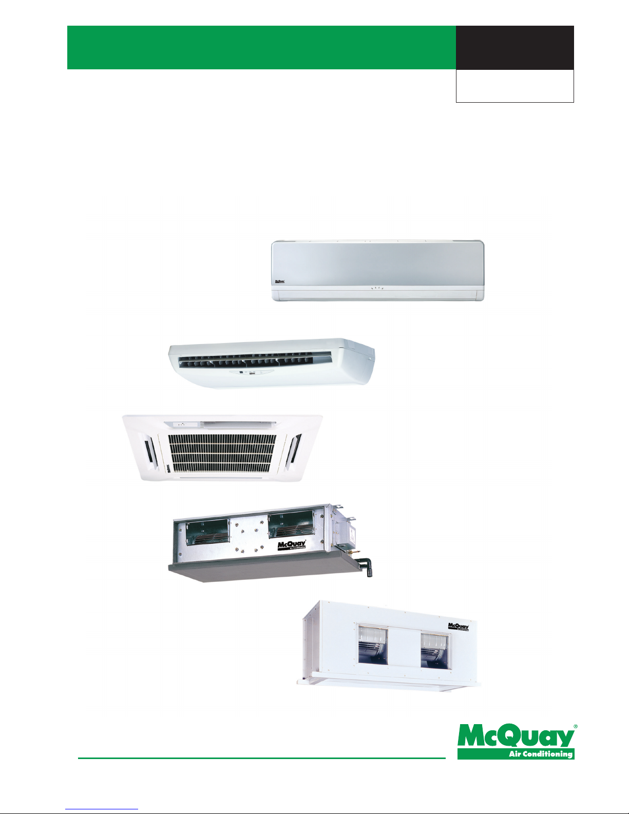
Fan Coil Units
Models:
MWM-G2W MCM-DW MCM-CW/EW
MCK-AW/CW MCC-CW MDB-BW
Technical Manual
Engineered for exibility and performance.™
MFCU_(ii)
Supercedes: MFCU_(i)
Page 2

Page 3

MFCU_(ii)
Table of Contents
Nomenclature...................................................................................................................... 1
Indoor
Product Line-Up
Application Information ..................................................................................................... 8
Operating Range
Installation Guideline
Sound data ........................................................................................................................ 16
Sound Pressure Level
Fan Performance Chart .................................................................................................... 19
Engineering and Physical Data
....................................................................................... 45
Performance Data
............................................................................................................. 56
Unit Selection Procedure
Performance Chart
Outlines & Dimensions .................................................................................................. 108
Wiring Diagrams
............................................................................................................. 133
Service & Maintainance
................................................................................................. 141
Troubleshooting
............................................................................................................. 142
Table of Contents
Supersedes: MFCU_(i)
“McQuay” is a registered trademark of McQuay International. All rights reserved.
© 2012 McQuay International. All rights reserved throughout the world.
Bulletin illustrations cover the general appearance of McQuay International products at the time of publication.
We reserve the right to change design and construction specications at any time without notice.
Page 4
Nomenclature
MFCU_(ii)
1
Indoor
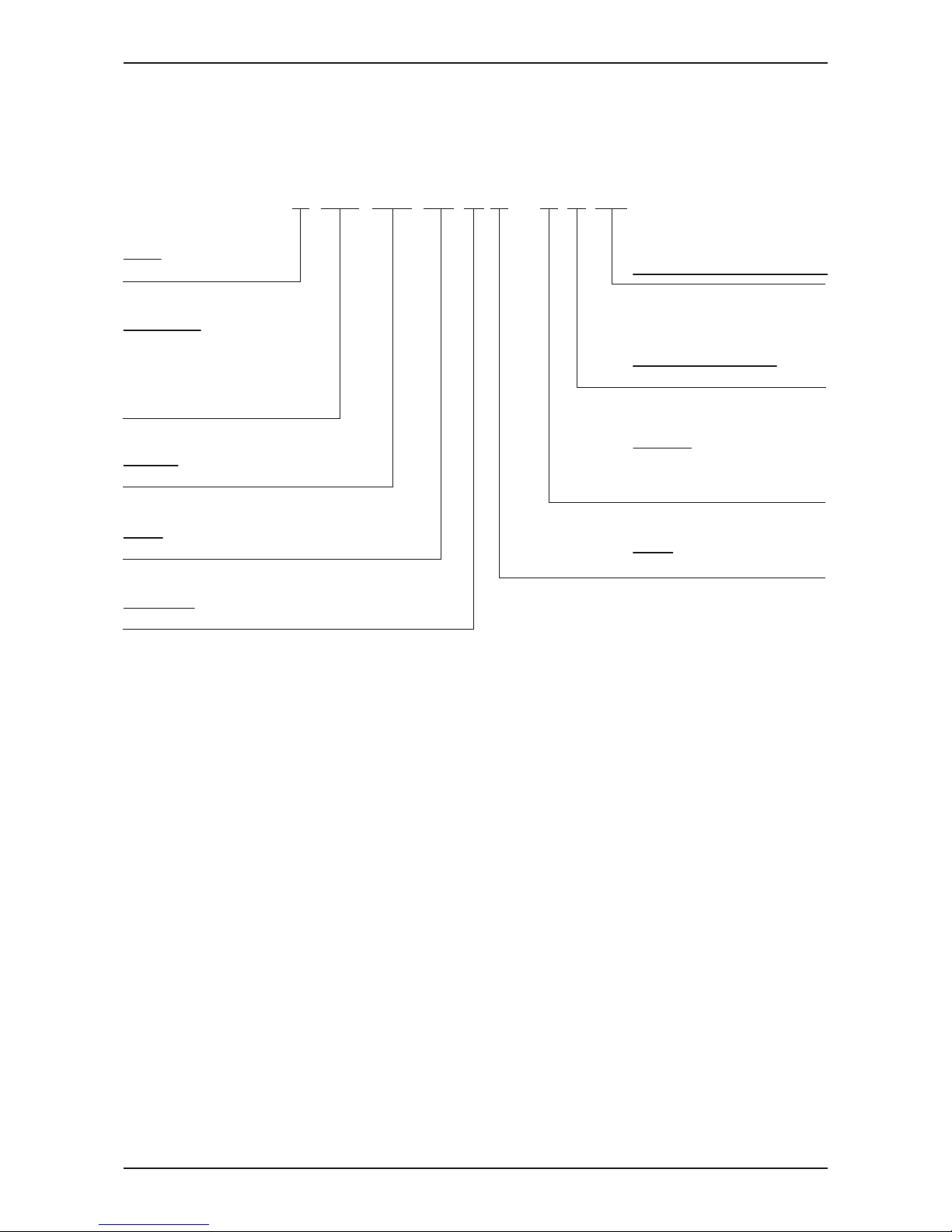
Nomenclature
Brand
M : McQuay
Product Specification Variation
Type of ref. connection
X : Not applicable
Piping
H : 4 pipes system
Electrical
A : 220 - 240V/1Ph/50Hz
F : 380 - 415V/3Ph/50Hz
U : 220 - 240V/1Ph/50Hz/60Hz
Model Name
WM : Wall Mounted Split Type
CK : Ceiling Cassette Split Type
CM : Ceiling Exposed Split Type
CC : Ceiling Concealed Split Type
DB : Ducted Split Type
Series
G2 : G2 series
Capacity
10 : 9,500 Btu/hr
Model Type
W : Chilled Water Fan Coil Unit
M WM 010 G2 W – A X AB
Page 5

MFCU_(ii)
Nomenclature
2
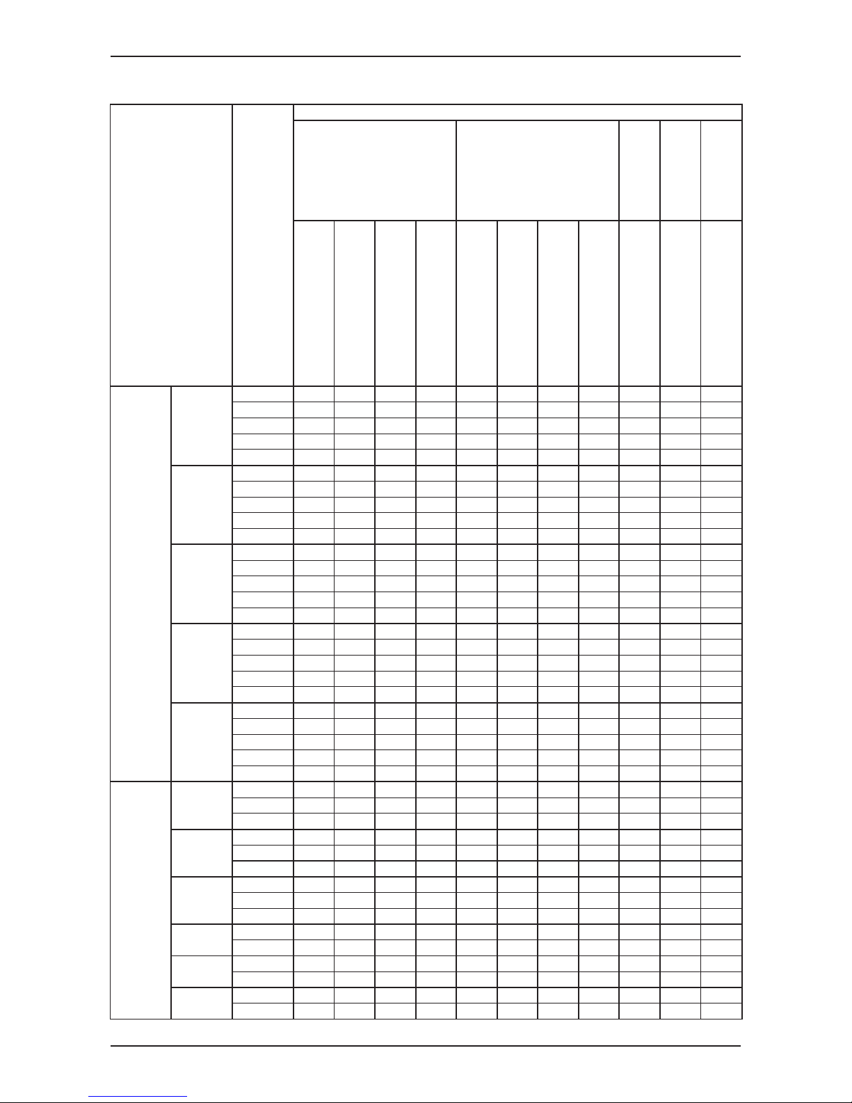
Product Line-Up
MWM-GW
Marking
PCB W2_L
Valve Application only
Auto Air Swing
Turbo
GS01 Cooling
GS01 Heat Pump
1/2" BSP (female) brass adaptor
Left piping
Nanosilver + Nanovis filter
Ionizer
Light Grey Chasis
Pure White Chasis
+
G2 silver coated facelift
Std Marking (CE)
MWM
007G2W
010G2W
015G2W
020G2W
025G2W
301W
Model Name
Nomenclature
Classification
Control
Handset
Connection
Filter
Panel
AXAL
AXAK
AXAL
AXAK
AXAL
AXAK
AXAL
AXAK
AXAL
AXAK
AXAE
AXAD
X
X
X
X
X
X
X
X
X
X
X
X
X
X
X
X
X
X
X
X
X
X
X
X
X
X
X
X
X
X
X
X
X
X
X X
X X
X X
X X
X X
X X
X X
X
X
X X
X
X X
X
X
X
X
X
X
X
X
X
X
X
X
X
X
X
X
X
X
X
X
X
X
X
X
X
X
X
X
X
X
X
X
X
X
X
X
X
X
X
X
X
X
X
X
X
X
X
X
X
X
X
X
X
X
X
X
X
X
X
X
X
X
X
X
X
X
X
X
X
X
X
X
X
Page 6
Nomenclature
MFCU_(ii)
3
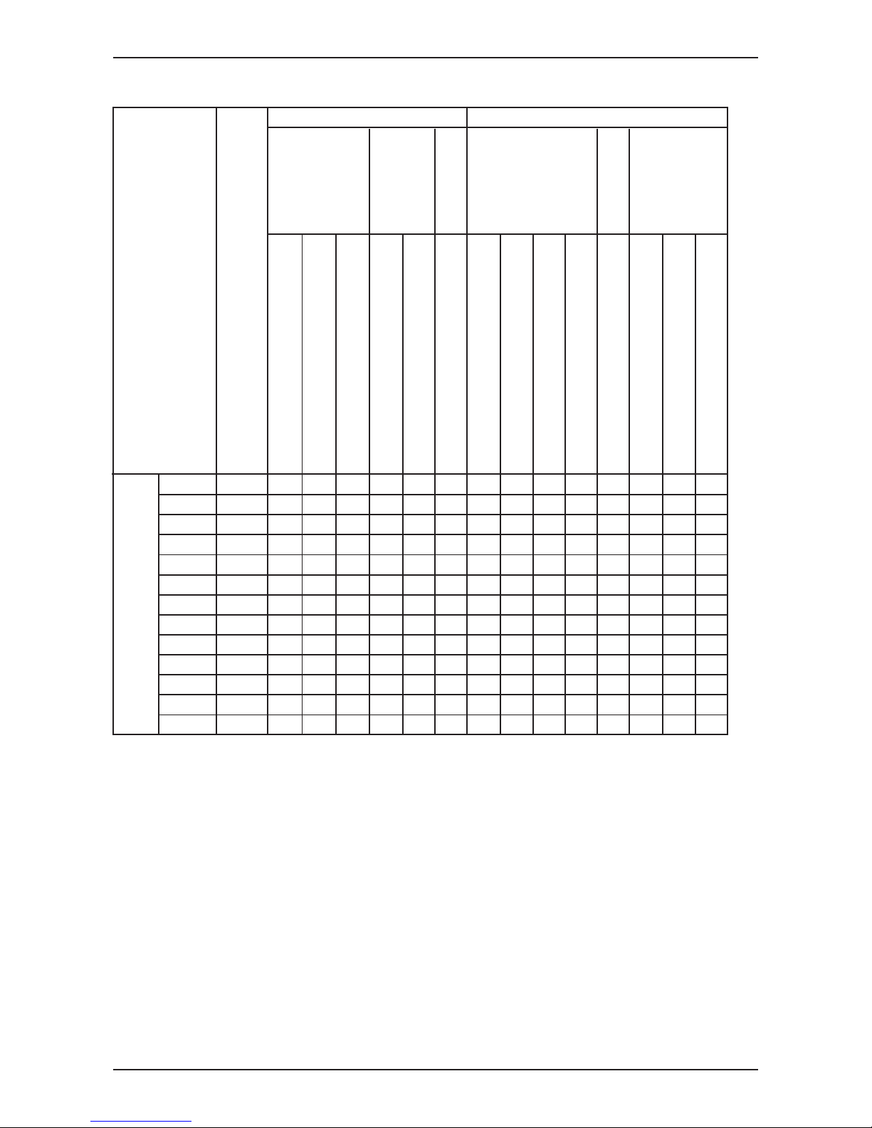
MCM-DW / MCM-CBW/EW
CONNECTION
FILTER
MARKING
UCW - W2.0
Valve / Valveless Application
Auto Air Swing
Without Controller
GS01 Cooling
GS01 Heat Pump
Netware 3 (Cool/Heat)
SLM3 Heat Pump
3/4" BHP (female) Union
Saranet Filter
Standard Marking (CE)
AXCE
X X X X X X X
AXCF
X X X X X X X
AXCG
X X X X X X
AXCH
X X X X X X X
AXCI
X X X X X X X
AXCE
X X X X X X X
AXCF
X X X X X X X
AXCG
X X X X X X
AXCH
X X X X X X X
AXCI
X X X X X X X
AXCE
X X X X X X X
AXCF
X X X X X X X
AXCG
X X X X X X
AXCH
X X X X X X X
AXCI
X X X X X X X
AXCE
X X X X X X X
AXCF
X X X X X X X
AXCG
X X X X X X
AXCH
X X X X X X X
AXCI
X X X X X X X
AXCE
X X X X X X X
AXCF
X X X X X X X
AXCG
X X X X X X
AXCH
X X X X X X X
AXCI
X X X X X X X
UXBF
X X X X X
UXBG
X X X X X X
UXBH
X X X X X X
UXBF
X X X X X
UXBG
X X X X X X
UXBH
X X X X X X
UXBF
X X X X X
UXBG
X X X X X X
UXBH
X X X X X X
AXAC
X X X X X X X
AXAD
X X X X X X X
AXAC
X X X X X X X
AXAD
X X X X X X X
AXAC
X X X X X X X
AXAD
X X X X X X X
MCM
025DW
030DW
040DW
050DW
MCM
007CBW
010CBW
015CBW
015EW
020EW
025EW
MODEL NAME
NOMENCLATURE
020DW
CLASSIFICATION
CONTROL
HANDSET
Page 7
MFCU_(ii)
Nomenclature
4
MCK-AW/CW/AWH
MARKING
MCK-AWH
UCW - W2.0
Valve / Valveless Application
Auto Air Swing (Panel)
4 pipe systems
3/4" BSP (female) brass union
Std Marking (CE)
PLCKAW-NNET3
PLCKAW-NSLM3HP
PLCKAW-NGS01 Cooling
PLCKAW-NGS01 Heat Pump
PLCKAWH-NGS01 Heat Pump
PLCKCW-NSLM3HP
PLCKCW-NGS01 Cooling
PLCKCW-NGS01 Heat Pump
MCK
MODEL NAME
NOMENCLATURE
CONTROL
CONNECTION
MCK-AW
MCK-CW
CLASSIFICATION
PANEL
020AW
025AW
030AW
040AW
050AW
020AWH
025AWH
030AWH
040AWH
050AWH
010CW
015CW
020CW
AXBE
AXBE
AXBE
AXBE
AXBE
AXAA
AXAA
AXAA
AXAA
AXAA
AXBA
AXBA
AXBA
X
X
X
X
X
X
X
X
X
X
X
X
X
X
X
X
X
X
X
X
X
X
X
X
X
X
X
X
X
X
X
X
X
X
X
X
X
X
X
X
X
X
X
X
X
X
X
X
X
X
X
X
X
X
X
X
X
X
X
X
X
X
X
X
X
X
X
X
X
X
X
X
X
X
X
X
X
X
X
X
X
X
X
X
X
X
X
X
X
X
X
X
X
X
X
X
X
X
X
X
X
X
X
X
Page 8
Nomenclature
MFCU_(ii)
5
FILTER
MARKING
UCW - W2.0
Valve / Valveless Application
Without Controller
Netware 3 (Coll/Heat)
SLM 3 Heat Pump
Left piping
Right piping
3/4" BSP (female) adaptor
Saranet Filter
Std Marking (CE)
MODEL NAME
NOMENCLATURE
CLASSIFICATION
CONTROL
HANDSET
CONNECTION
MCC
010CW
015CW
020CW
025CW
028CW
AXAK
AXBC
AXAJ
AXAC
AXBA
AXAK
AXBC
AXAJ
AXAC
AXBA
AXAK
AXBC
AXAJ
AXAC
AXBA
AXAK
AXBC
AXAJ
AXAC
AXBA
AXAK
AXBC
AXAJ
AXAA
AXBA
X
X
X
X
X
X
X
X
X
X
X
X
X
X
X
X
X
X
X
X
X
X
X
X
X
X
X
X
X
X
X
X
X
X
X
X
X
X
X
X
X
X
X
X
X
X
X
X
X
X
X
X
X
X
X
X
X
X
X
X
X
X
X
X
X
X
X
X
X
X
X
X
X
X
X
X
X
X
X
X
X
X
X
X
X
X
X
X
X
X
X
X
X
X
X
X
X
X
X
X
X
X
X
X
X
X
X
X
X
X
X
X
X
X
X
X
X
X
X
X
X
X
X
X
X
X
X
X
X
X
X
X
X
X
X
X
X
X
X
X
X
X
X
X
X
X
X
X
X
X
X
X
X
X
X
X
X
X
X
X
X
X
X
X
X
MCC-CW
Page 9
MFCU_(ii)
Nomenclature
6
MCC-CW
FILTER
MARKING
UCW - W2.0
Valve / Valveless Application
Without Controller
Netware 3 (Coll/Heat)
SLM 3 Heat Pump
Left piping
Right piping
3/4" BSP (female) adaptor
Saranet Filter
Std Marking (CE)
MODEL NAME
NOMENCLATURE
CLASSIFICATION
CONTROL
HANDSET
CONNECTION
MCC
030CW
038CW
040CW
050CW
060CW
AXAK
AXBC
AXAJ
AXAC
AXBA
AXAK
AXBC
AXAJ
AXAA
AXBA
AXAK
AXBC
AXAJ
AXAA
AXBA
AXAK
AXBC
AXAJ
AXAA
AXBA
AXAK
AXBC
AXAJ
AXAA
AXBA
X
X
X
X
X
X
X
X
X
X
X
X
X
X
X
X
X
X
X
X
X
X
X
X
X
X
X
X
X
X
X
X
X
X
X
X
X
X
X
X
X
X
X
X
X
X
X
X
X
X
X
X
X
X
X
X
X
X
X
X
X
X
X
X
X
X
X
X
X
X
X
X
X
X
X
X
X
X
X
X
X
X
X
X
X
X
X
X
X
X
X
X
X
X
X
X
X
X
X
X
X
X
X
X
X
X
X
X
X
X
X
X
X
X
X
X
X
X
X
X
X
X
X
X
X
X
X
X
X
X
X
X
X
X
X
X
X
X
X
X
X
X
X
X
X
X
X
X
X
X
X
X
X
X
X
X
X
X
X
X
X
X
X
X
X
Page 10
Nomenclature
MFCU_(ii)
7
MDB-BW
MARKING
Valveless Application
Without Controller
Brazing (OD28.6mm, 1 1/8")
Right Piping
Left Piping
Horizontal Flow
Vertical flow
Saranet Filter
R15 / R29 Filter
Standard Marking (CE)
AXAA X X X X X X X
AXAB X X X X X X X
AXAA X X X X X X X
AXAB X X X X X X X
FXAA X X X X X X X
FXAB X X X X X X X
FXAC X X X X X X X
FXAD X X X X X X X
FXAA X X X X X X X
FXAB X X X X X X X
FXAC X X X X X X X
FXAD X X X X X X X
075BW
100BW
125BW
150BW
MDB
MODEL NAME
NOMENCLATURE
CLASSIFICATION
CONTROL
CONNECTION
Discharge
FILTER
Page 11
MFCU_(ii)
Application Information
8
Application Information
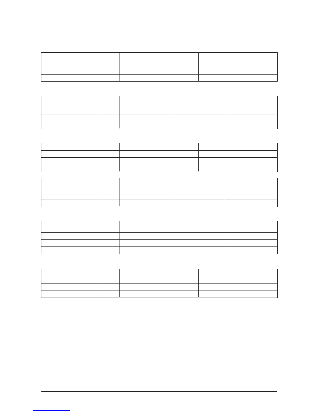
Operating Range
Operating Limits:
Thermal carrier : Water
Water temperature : 5 ~ 50°C
Maximum water pressure : 16 bar
Air temperature : (as below)
Cooling Mode
Temperature Ts °C/°F Th °C/°F
Minimum indoor
16.0 / 60.8 11.0 / 51.8
32.0 / 89.6 23.0 / 73.4
16.0 / 60.8 -
46.0 / 114.8 -
temperature
Maximum indoor
temperature
Minimum outdoor
temperature
Maximum outdoor
temperature
Temperature Ts °C/°F Th °C/°F
Minimum indoor
temperature
Maximum indoor
temperature
Minimum outdoor
temperature
Maximum outdoor
temperature
Heating Mode
Ts: Dry bulb temperature. Th: Wet bulb temperature.
16.0 / 60.8 -
30.0 / 86.0 -
-5.0 / 23.0 -6.0 / 21.2
24.0 / 75.2 18.0 / 64.4
Installation Guide
System Conguration
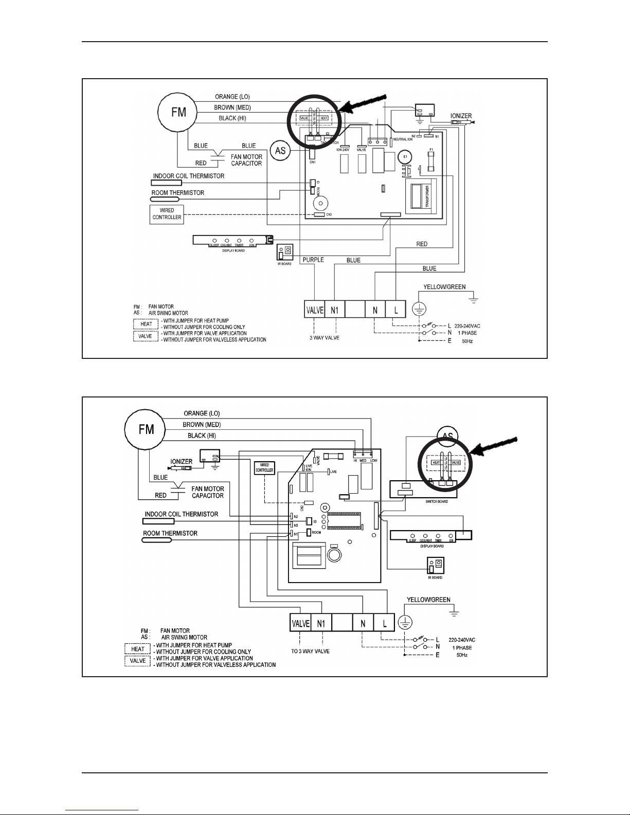
The standard controller board (W2) comes with a VALVE jumper and a HEAT jumper. The system can be
congured as the jumper selection listed below:
VALVE & HEAT Jumper Location
Model: MWM - G2W / 301W
1. VALVE jumper is plugged into JVLV connector on the emergency switch board.
2. HEAT jumper is plugged into JMODE connector on the emergency switch board.
Model: MCK-AW/AWH/CW, MCM-DW/CBW/EW and MCC-CW
1. VALVE jumper is plugged into JVLV connector on the main board.
2. HEAT jumper is plugged into OD connector on the main board.
HEAT Jumper VALVE Jumper
Heatpump Mode & Valve Application √ √
Heatpump Mode & Valveless Application √ X
Cooling Mode & Valve Application X √
Cooling Mode & Valveless Application X X
√ Jumper Remained X Jumper Removed
Caution
Disconnect the power supply to the unit before attempting to connect the wiring
Page 12
Application Information
MFCU_(ii)
9
Model : MWM 007/010/015G2W (IONIZER)
Model : MWM 020/025G2W (IONIZER)
Page 13
MFCU_(ii)
Application Information
10
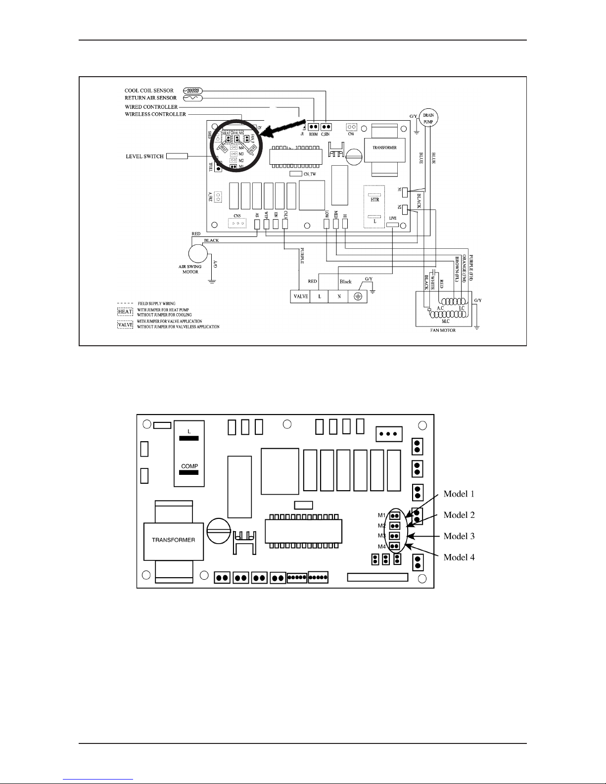
Model : MCM Series / MCC Series / MCK-AW/CW
MCK-AWH 4 pipes system controller board setting
A) Model selection
The standard controller board (W2.0) comes with a default setting for model selection. Please select the model
accordingly by using jumper.
Page 14

Application Information
MFCU_(ii)
11
System Model Function
2 Pipe
System
4 Pipe
System
M1 Model 1
M2 Model 2
M3 Model 3
M4 Model 4
Cooling or Heating
Cooling or Heating with Auxiliary Heater
Cooling Only with Boiler
Cooling or Heating with Boiler
B) Valve, Heat and Fan priority selection
Jumper With Jumper (Default) Without Jumper
Fan Priority Jumper User set speed or lower fan if auto Fan stop when thermostat cut off
mode is selected
Heat Jumper For Heat pump For cooling only
Valve Jumper For Valve control (Model 1,2,3 & 4) For valveless control (Model 1 & 2)
Page 15
MFCU_(ii)
Application Information
12
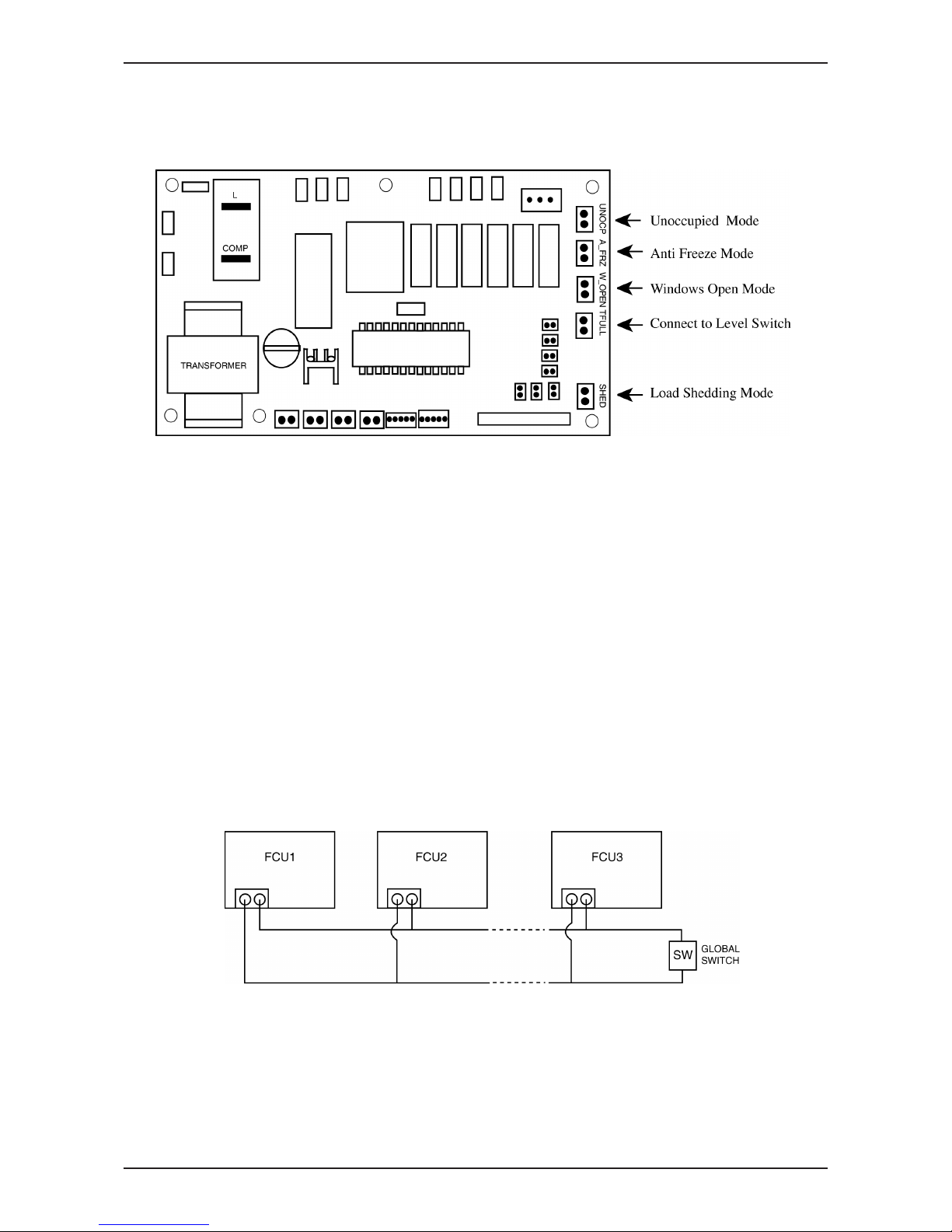
C) Others
The controller board comes with other option.
i) Unoccupied Mode
If the dry contact is closed, the Unoccupied mode is activated and vice versa. When Timer On is active,
system goes back to Occupied mode.
The dry contact connection points can be connected parallel with other fan coil unit (FCU) boards. If the
dry contact is closed, Unoccupied mode will be activated on all fan coil units that are connected parallel as
shown in gure below.
ii) Anti Freeze Mode
Anti Freeze operation has the highest priority among all unit operation. Anti Freeze operation will be activated
only if dry contact is closed and vice versa.
iii) Window Open Mode
The dry contact connection points can be connected in parallel with other fan coil unit (FCU) boards. If the
dry contact is closed, Window open mode will be activated on all the fan coil units which are connected in
parallel as shown in gure below.
iv) Load Shedding
The dry contact connection points can be connected in parallel with other fan coil unit (FCU) boards. If the
dry contact is closed, Load shedding mode will be activated on all the fan coil units which are connected in
parallel as shown in gure below.
Global Unoccupied, Global Window Open and Global Load Shedding operation could also be activated via the
network communication bus line by master controller with or without the above connection.
NOTE :
i) Auto Fan Mode is only applicable in Model 3 only. ( Cooling only with Boiler)
ii) Fan mode is not available in valveless control.
iii) Wired handset (Netware and SLM) has an indoor room sensor. Avoid locating the wired handset at isolated
places where room temperature reading will be inaccurate.
Page 16
Application Information
MFCU_(ii)
13
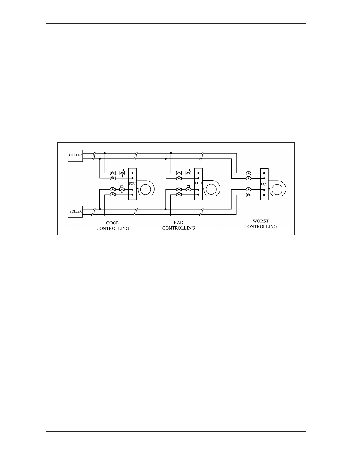
Water Piping Connection
The indoor unit is equipped with water outlet and inlet bare connection. There is an air-vent for air purging that
is tted at the outlet water header.
3 ways solenoid valve is required for cycling off or bypass the chilled water.
Black steel pipe, polyethrene pipe, PVC pipe and copper tube recommended in eld installation.
All types of piping and connection must be insulated by polyurethane (ARMAFLEX type or equivalent) to avoid
condensation.
Do not use contaminated or damaged pipe and tting for installation.
Some main tting components are needed in the system to enhance the capacity and ease of service, such as
gate valve, balancing valve, 2 ways or 3 ways solenoid valve, lter, strainer etc.
Preliminary Site Survey
Electrical supply and installation is to conform to LOCAL AUTHORITY’s (e.g. National Electricity Board) CODES
and REGULATIONS.
Voltage supply uctuation must not exceed ± 10% of rated voltage. Electricity supply lines must be independent
of welding transformers which can cause supply uctuation.
Ensure that the location is convenient for wiring and piping.
Mounting
For ceiling mounted models, locate a position where piping and ducting work can be kept to a minimum. Ensure
that overhead supports are strong enough to hold the unit’s weight. Position hanger rods and check for alignment
with the unit. Check that hangers are secure and that the base of fan coil unit is level in two horizontal positions.
Piping
Drain and water piping must be accurately connected.
Please refer to “Specication Sheet” for piping sizes.
Page 17

MFCU_(ii)
Application Information
14
Piping Support
All water mains must be adequately supported to carry the necessary weight involved, provisions must be made
by the installing contractor to allow for adequate free movement of all vertical and horizontal risers and run outs.
Due to the fact that cold water will be circulated through the water mains, a sizeable movement of the water
mains can be expected due to contraction. If for example, the piping is rigidly supported with no provision for
movement, it is very possible that the tubing of tting may be broken causing water leakage in the conditioned
spaces throughout the building.
Coil Venting
Each standard basic unit coil is equipped with a manually operated air vent which is installed at the end of a
small copper line leading into the highest point of the coil. By means of this valve, air may be vented manually,
from the coil to keep it operating at full capacity. When water is rst introduced into a coil, air is sometimes
trapped in the coil tubing. This trapped air will reduce cooling capacity and create “Bubbling” or “Clanking” noise
within the units. To release air trapped in the coil, press the air vent head to allow air to ow out of the air vent
opening. Release when a steady stream of water appear.
Electrical Connection
As wiring regulations differ from country to country, please refer to your LOCAL ELECTRICAL CODES for eld
wiring regulations and ensure that they are complied with. Besides, take note of the following general precaution:
1) Ensure that the rated voltage of the unit corresponds to the name plate before commencing wiring work.
2) Provide a power outlet to be used exclusively for each unit and a power supply disconnect and a circuitbreaker for over-current protection should be provided in the exclusive line.
3) The unit must be EARTH to prevent possible hazards due to insulation failure.
4) All wiring must be rmly connected.
Page 18
Application Information
MFCU_(ii)
15
Model Unit MWM 007/010/015/020/025G2W MWM 301W
Power supply cable size* mm²
mm²
mm²
mm²
mm²
mm²
1.5 2.5
3
2
Number of wire 3
Recommended fuse* A 2
Model Unit MCK 010/015/020CW
MCK 020/025/030/
040/050AW
MCK 020/025/030/
040/050AWH
Power supply cable size* 1.5 1.5 1.5
Number of wire 3 3 3
Recommended fuse* A 2 2 2
Model Unit MCM 007/010/015CBW MCK 020/025/030/040/050DW
Power supply cable size* 1.5 1.5
Number of wire 3 3
Recommended fuse* A 2 2
Model Unit MCM 015EW MCM 020EW MCM 025EW
Power supply cable size* 2.5 2.5 4.0
Number of wire 3 3 3
Recommended fuse* A 2 2 2
Model Unit MCC 010/015/020CW MCC 025CW
MCK 028/030/038/
040/050/060CW
Power supply cable size* 1.5 2.5 2.5
Number of wire 3 3 3
Recommended fuse* A 10 10 16
Model Uni
t
MDB 075/100BW
MDB 125/150BW
Power supply cable size*
1.5
1.5
Number of wire
3
4
Recommended fuse* A
5
5
Important: * These values are for information only. They should be checked and selected to comply local
or national codes and regulations. They are also subjected to the type of installation and size of conductors.
Cable Size
Wall Mounted
Page 19
MFCU_(ii)
Sound Data
16
Sound Data
Sound Pressure Level
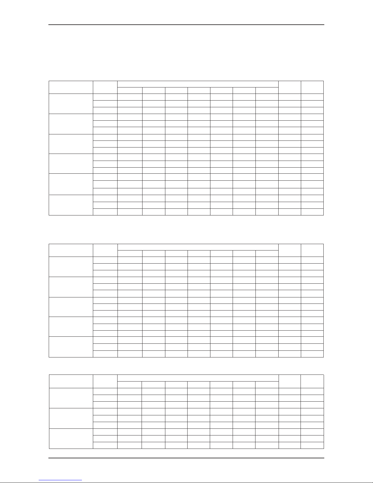
Wall Mounted Split Type
1/1 Octave Sound Pressure Level (dB, reference 20µPa)
MWM015G2W
MWM020G2W
MWM025G2W
MWM301W
MWM007G2W
MWM010G2W
Microphone position : ACK20/25AW/AWH -- 1.4m below the facia. (JIS C 9612)
ACK30/40/50AW/AWH -- 1.5 m below the facia. (JIS B 8615)
Overall
125Hz 250Hz 500Hz 1kHz 2kHz 4kHz 8kHz (dBA) Criteria
High 46 45 40 38 32 21 14 42 37
Medium 44 43 37 33 28 18 12 39 32
Low 43 42 35 31 26 17 11 37 31
High 48 46 43 39 33 27 19 45 38
Medium 45 43 40 35 29 21 15 42 35
Low 43 42 38 32 27 19 14 40 33
High 50 48 47 43 37 35 28 49 42
Medium 48 45 43 38 32 31 27 45 38
Low 46 43 41 35 30 30 26 43 36
High 50 49 49 46 39 38 31 51 45
Medium 48 47 47 43 36 34 25 48 42
Low 46 45 46 41 34 30 23 46 41
High 54 52 51 48 43 42 34 53 47
Medium 52 50 50 46 41 40 32 52 46
Low 51 49 49 45 39 39 31 50 45
MCK025AW/AW H
MCK030AW/AW H
MCK040AW/AW H
MCK050AW/AW H
Model
MCK020AW/AW H
Ceiling Cassette Split Type
Speed
Noise
1/1 Octave Sound Pressure Level (dB, reference 20µPa)
Overall
125Hz 250Hz 500Hz 1kHz 2kHz 4kHz 8kHz (dBA) Criteria
Model
Speed
Noise
High 33 33 36 34 28 19 7 38 33
Medium 31 29 32 29 23 13 5 33 28
Low 26 25 27 23 17 8 5 28 21
High 28 34 37 36 31 22 13 39 35
Medium 27 30 33 31 25 17 12 34 30
Low 24 26 28 25 19 12 11 28 23
High 30 35 39 38 33 25 15 42 37
Medium 28 31 34 33 26 18 13 36 32
Low 24 26 28 26 20 13 12 29 24
High 41 48 47 43 40 32 23 49 43
Medium 39 44 43 39 35 28 20 44 38
Low 37 41 40 36 32 25 19 42 35
High 40 48 48 45 44 35 27 50 45
Medium 38 46 47 42 42 33 25 48 43
Low 36 42 44 39 38 29 23 45 39
High 42 46 45 44 41 35 28 49 43
Medium 40 45 44 43 38 33 27 47 42
Low 37 43 43 40 35 30 26 45 39
Overall Noise
125 Hz 250 Hz 500 Hz 1000 Hz 2000 Hz 4000 Hz 8000 Hz (dBA) Criteria
High 44 45 40 36 26 19 10 42 35
Medium 40 38 34 28 19 9 7 35 29
Low 37 32 27 20 14 6 7 29 21
High 48 48 44 38 31 27 15 45 39
Medium 42 42 36 30 22 13 7 38 31
Low 39 36 28 20 15 6 6 30 23
High 52 50 46 41 34 31 19 48 41
Medium 43 43 38 33 26 18 8 40 33
Low 41 39 35 28 22 10 7 36 30
MCK020CW
Model
Speed
1/1 Octave Sound Pressure Level (dB, reference 20µPa)
MCK010CW
MCK015CW
Microphone position : AWM-G2W -- 1 m in front of the unit and 0.8 m below the vertical centre line of the unit. (JIS C 9612)
AWM301W -- 1 m in front and 1 m below the air discharge opening of the unit (JIS B 8615)
Microphone position : 1.4m below the facia. (JIS C 9612)
Page 20
Sound Data
MFCU_(ii)
17
Model
1/1 Octave Sound Pressure Level (dB, ref 20μPa)
1/1 Octave Sound Pressure Level (dB, ref 20μPa)
1/1 Octave Sound Pressure Level (dB, ref 20μPa)
High
26 34 38 42 38 35 23 45 41
Medium
23 29 36 39 34 31 18 42 38
Low
19 26 33 34 31 23 12 37 33
High
27 35 39 43 39 36 24 46 42
Medium
24 30 37 40 35 32 19 43 39
Low
20 27 34 35 32 24 13 38 34
High
28 36 40 44 40 37 25 47 43
Medium
25 31 38 41 36 33 20 44 40
Low
21 28 35 36 33 25 13 39 35
Model
Speed
Overall
125Hz 250Hz 500Hz 1kHz 2kHz 4kHz 8kHz (dBA) Criteria
125Hz 250Hz 500Hz 1kHz 2kHz 4kHz 8kHz (dBA) Criteria
Noise
Overall
Noise
Speed
MCM007CBW
MCM010CBW
MCM015CBW
Microphone position: 1m in front and 0.8m below the vertical centre line of the unit.
High
45 46 47 46 41 38 29 50 45
Medium
42 43 45 42 38 34 24 47 41
Low
36 37 39 35 31 24 15 40 34
High
48 51 51 50 45 41 33 54 49
Medium
47 50 50 49 44 40 32 53 48
Low
45 47 48 47 41 36 27 50 46
High
45 48 48 47 43 33 24 51 46
Medium
44 47 47 46 42 32 23 50 45
Low
43 45 45 44 39 29 20 48 43
High
51 53 51 50 47 37 30 54 49
Medium
48 51 50 49 46 36 28 53 48
Low
46 50 49 48 44 35 27 52 47
High
51 53 51 50 47 37 30 54 49
Medium
48 51 50 49 46 36 28 53 48
Low
46 50 49 48 44 35 27 52 47
Microphone position : MCM 020/025DW -- 1 m in front of the unit and 0.8 m below the air discharge opening. (JIS C 9612)
MCM 030/040/050DW -- 1 m in front of the unit and 1 m below the air discharge opening. (JIS B 8615)
MCM040DW
MCM050DW
MCM020DW
MCM025DW
MCM030DW
Ceiling Exposed Split Type
Overall Noise
125 Hz 250 Hz 500 Hz
1000 Hz
2000 Hz
4000 Hz
8000 Hz
(dBA)
Criteria
High 42 46 49 44 43 36 31 50 45.0
Medium 36 40 43 37 36 27 20 43 38.0
Low 34 38 41 34 33 23 15 41 36.0
High 45 47 51 48 47 40 34 53 48.0
Medium 43 46 49 46 44 37 31 51 45.0
Low 42 46 47 44 42 35 27 49 43.0
High 47 50 53 50 50 43 39 56 51.0
Medium 44 46 49 46 45 38 33 51 46.0
Low 38 40 43 38 37 28 22 44 38.0
MCM025EW
Model
Speed
MCM015EW
MCM020EW
Microphone position: MCM 015/020/025EW -- 1 m in front of the unit and 1 m below the air discharge opening. (JIS B 8615)
Page 21
MFCU_(ii)
Sound Data
18
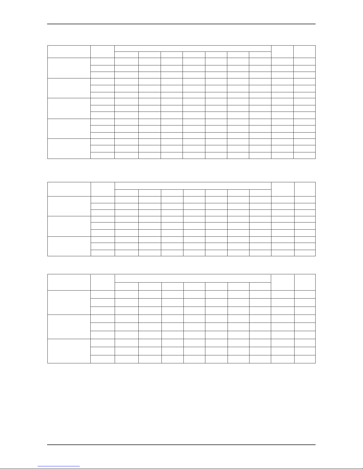
Ceiling Concealed Fan Coil Unit
Ducted Split Fan Coil Unit
Overall Noise
125 Hz 250 Hz 500 Hz
1000 Hz
2000 Hz
4000 Hz
8000 Hz
(dBA)
Criteria
High 33 30 30 29 22 16 10 33 27
Medium 31 28 28 26 20 13 8 30 24
Low 28 25 24 22 16 10 7 26 20
High 39 36 34 32 27 18 11 37 31
Medium 35 34 32 29 23 14 9 34 27
Low 32 29 28 25 17 11 8 29 23
High 42 39 36 24 28 22 17 38 33
Medium 41 37 34 31 26 20 15 36 30
Low 40 36 32 29 23 18 13 34 27
High 42 41 37 34 31 29 23 40 33
Medium 41 40 36 33 29 28 22 39 32
Low 36 35 33 31 26 27 21 36 30
High 45 42 39 35 31 26 22 41 34
Medium 42 38 37 32 28 22 17 38 32
Low 36 33 33 27 23 16 11 34 27
High 50 45 43 42 37 31 26 46 41
Medium 45 40 40 38 32 26 20 42 37
Low 42 36 37 33 28 22 15 38 32
High 54 51 48 46 41 36 31 51 45
Medium 51 48 46 45 37 32 26 48 44
Low 47 45 44 41 34 28 22 45 40
High 54 47 47 45 39 35 29 49 44
Medium 49 42 43 41 35 31 24 45 40
Low 45 39 41 37 30 26 18 41 36
High 54 49 49 48 43 37 32 52 47
Medium 53 47 46 47 40 35 29 50 46
Low 51 45 44 44 36 32 26 47 43
High 55 49 49 50 44 37 33 53 49
Medium 53 46 47 47 39 34 28 50 46
Low 51 43 44 43 35 30 24 47 42
Model
Speed
1/1 Octave Sound Pressure Level (dB, reference 20µPa)
MCC010CW
MCC015CW
MCC050CW
MCC060CW
MCC020CW
MCC025CW
MCC028CW
MCC030CW
MCC038CW
MCC040CW
Microphone position : 1.5m below the centre of the unit.
Tested with 2m length duct at the air discharge outlet and air return inlet.
Microphone position : 1.5m above the centre of the unit.
Tested with 2m length duct at the air discharge outlet and air return inlet.
Overall Noise
125 Hz 250 Hz 500 Hz 1000 Hz 2000 Hz 4000 Hz 8000 Hz
(dBA) Criteria (NC)
MDB075BW
55 54 54 51 49 44 36 56 50
MDB100BW
56 55 55 52 50 45 37 57 51
MDB125BW
57 55 56 53 51 46 38 58 53
MDB150BW
57 55 56 53 51 46 38 58 53
Model
1/1 Octave Sound Pressure Level (dB, reference 20µPa)
Page 22
Fan Performance Chart
MFCU_(ii)
19
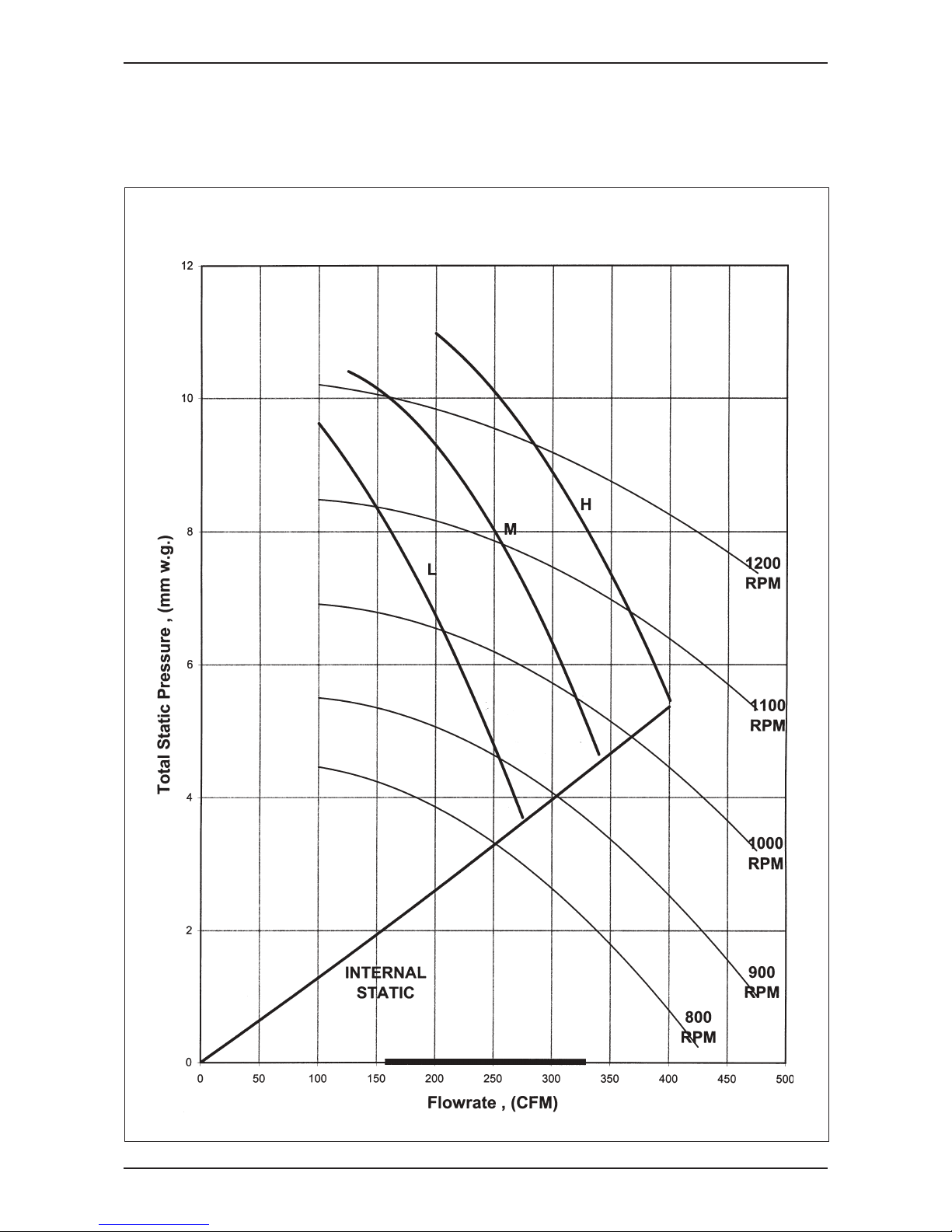
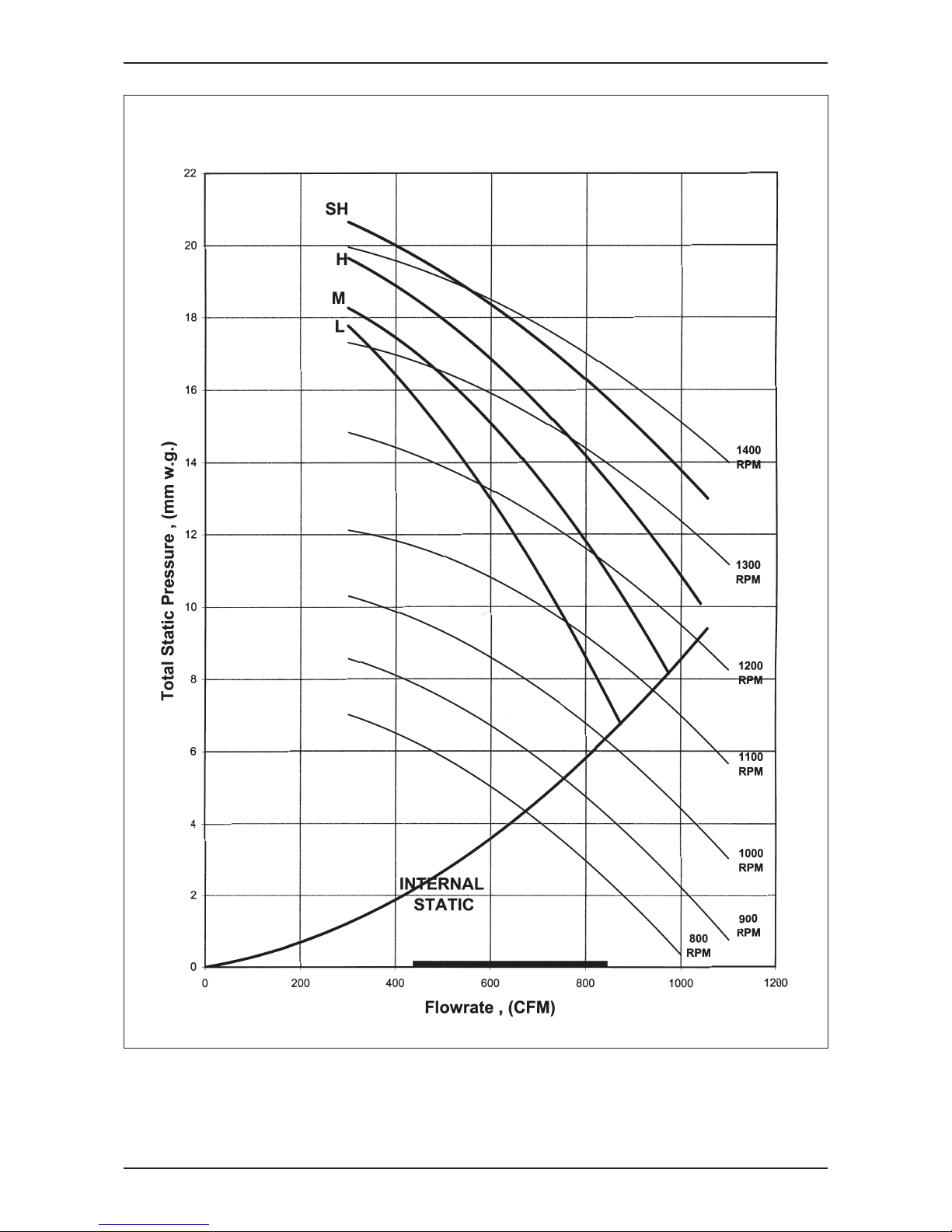
Fan Performance Chart
MCC 010CW
Fan Performance Curve
Page 23
MFCU_(ii)
Fan Performance Chart
20
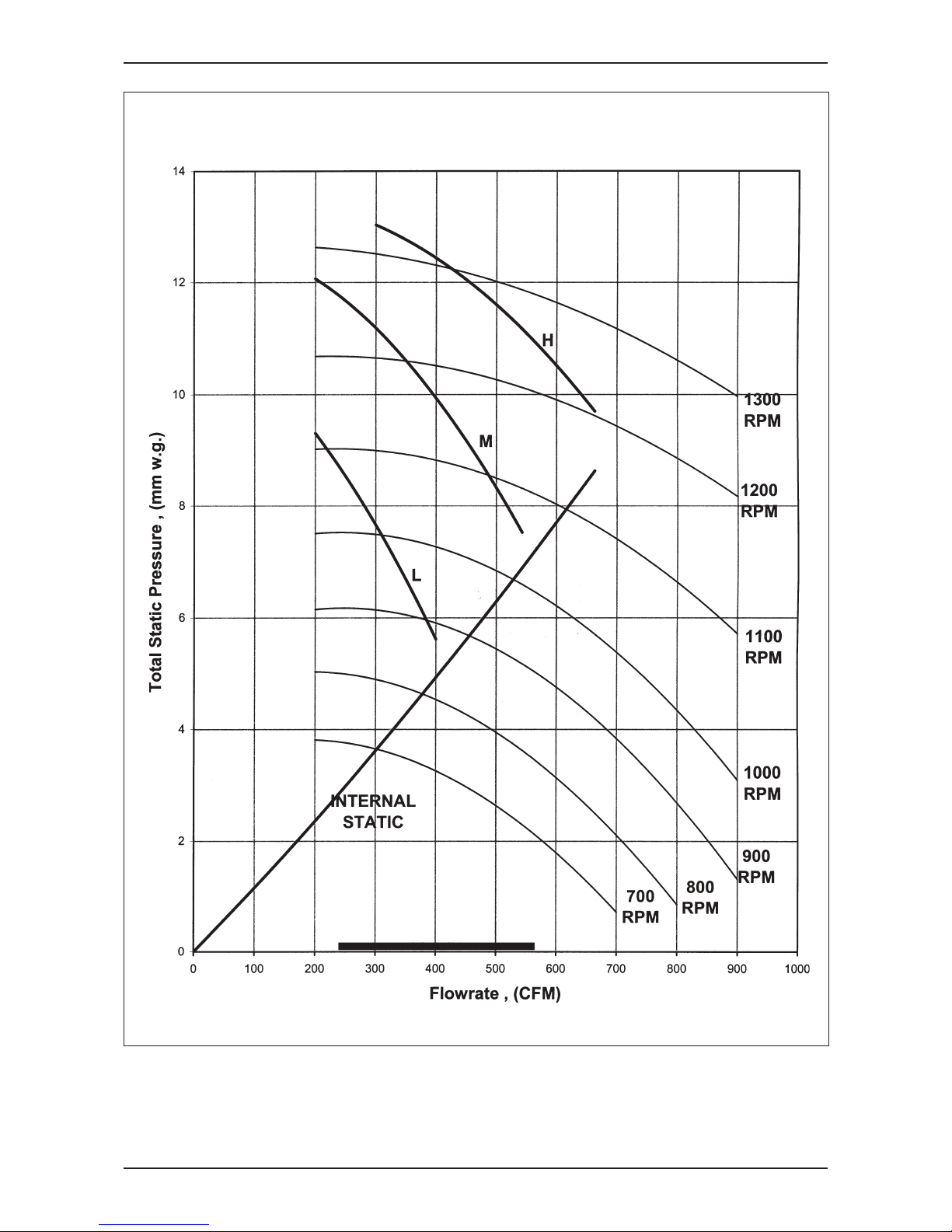
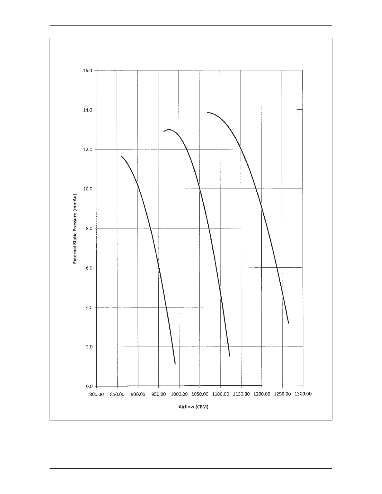
MCC 015CW
Page 24
Fan Performance Chart
MFCU_(ii)
21
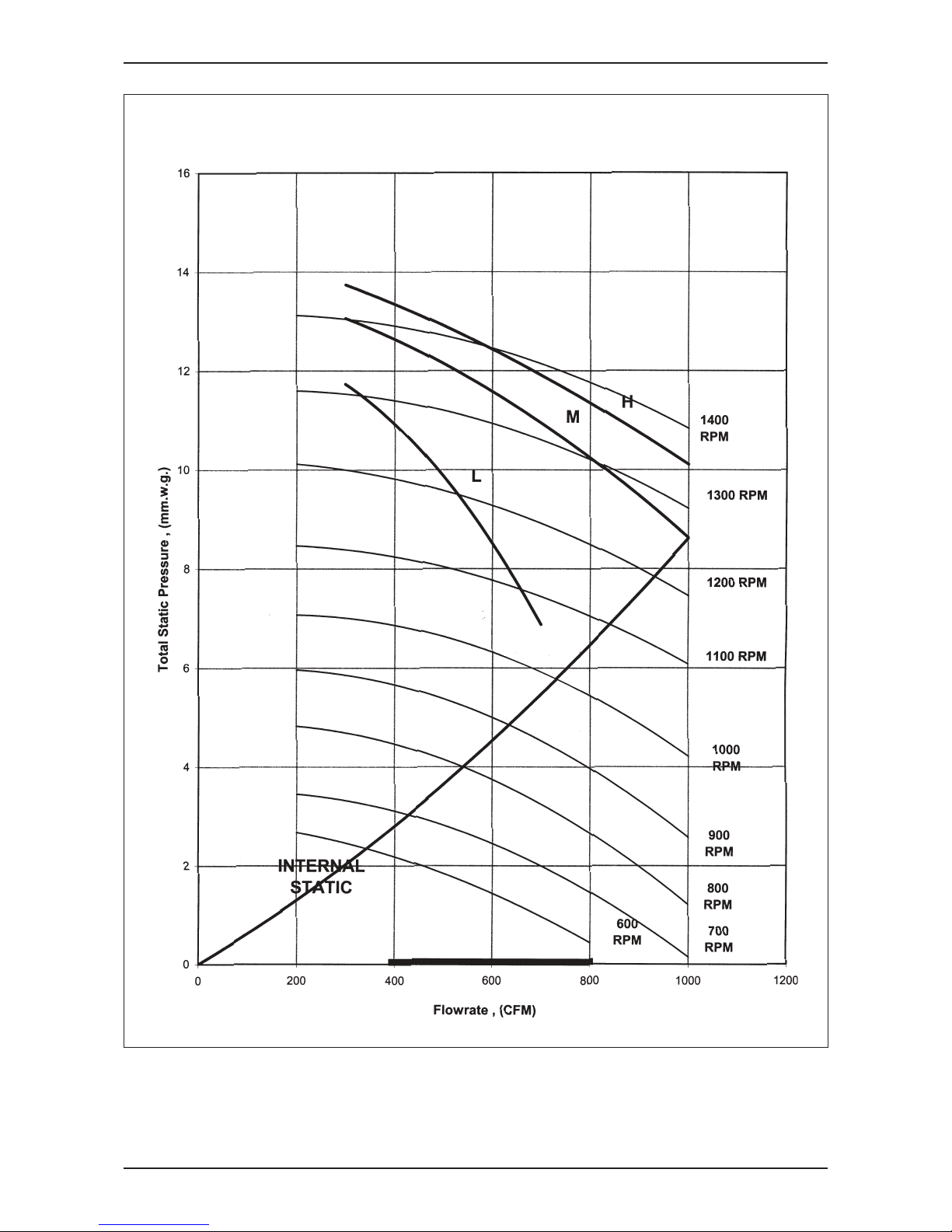
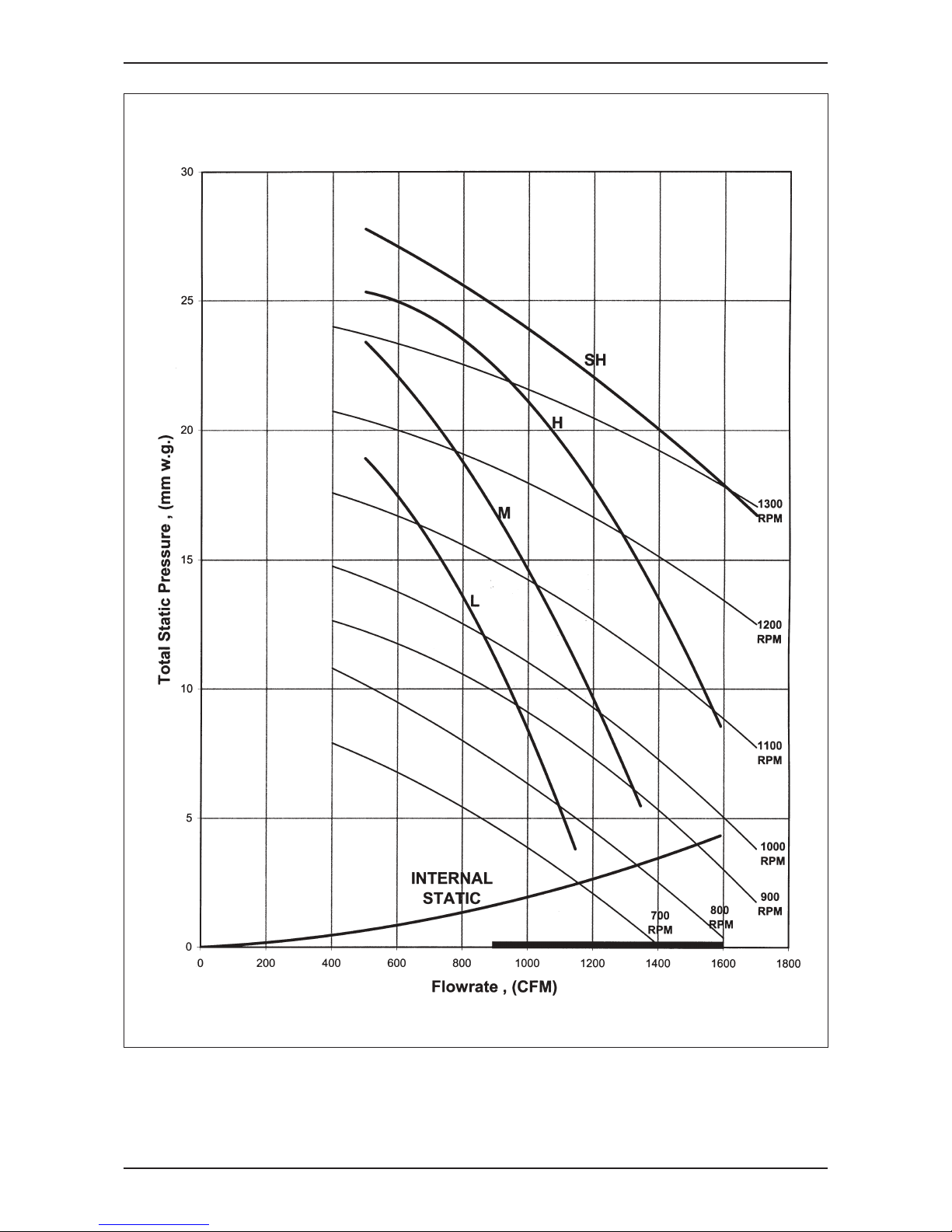
MCC 020CW
Page 25
MFCU_(ii)
Fan Performance Chart
22
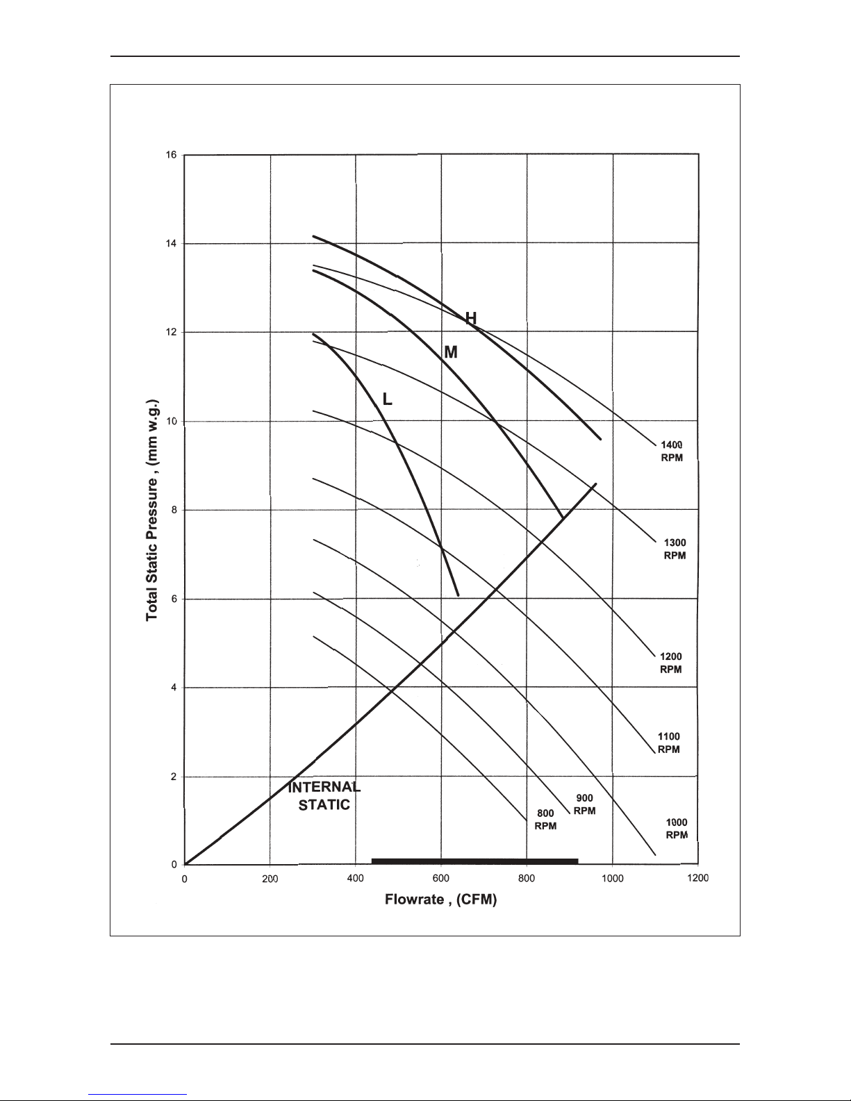
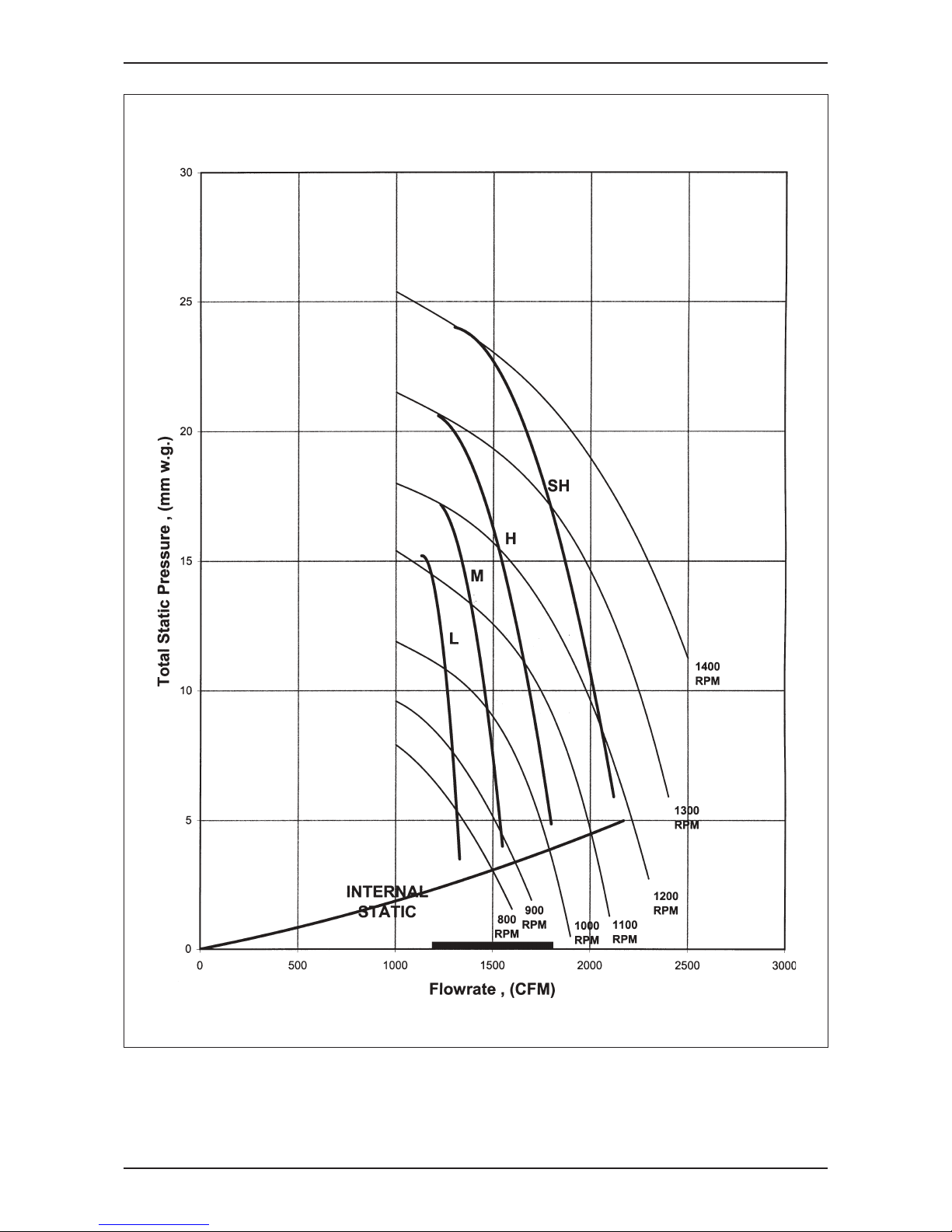
MCC 025CW
Page 26
Fan Performance Chart
MFCU_(ii)
23
MCC 028CW
Page 27

MFCU_(ii)
Fan Performance Chart
24
MCC 030CW
Page 28
Fan Performance Chart
MFCU_(ii)
25
MCC 038CW
Page 29
MFCU_(ii)
Fan Performance Chart
26
MCC 040CW
Page 30
Fan Performance Chart
MFCU_(ii)
27
MCC 050CW
Page 31

MFCU_(ii)
Fan Performance Chart
28
MCC 060CW
Page 32

Fan Performance Chart
MFCU_(ii)
29
MDB 075BW
Page 33

MFCU_(ii)
Fan Performance Chart
30
MDB 100BW
Page 34

Fan Performance Chart
MFCU_(ii)
31
MDB 125BW
Page 35

MFCU_(ii)
Fan Performance Chart
32
MDB 150BW
Page 36

Fan Performance Chart
MFCU_(ii)
33
Wall Mounted Split Type
Note :
a. PRESSURE DROP CORRECTION FACTOR = 1.2947 - 0.0021 * ( EWT°C * 1.8 + 32 )
b. PRESSURE DROP CORRECTION FACTOR = 1.2947 - 0.0021 * EWT°F
Water Flow Vs Pressure Drop
LITRES/M USGPM kPa PSI
4.00 1.06 20.23 2.93
5.33 1.41 27.04 3.92
6.66 1.76 33.88 4.91
7.99 2.11 40.75 5.91
9.32 2.46 47.65 6.91
4.79 1.27 26.96 3.91
6.39 1.69 36.00 5.22
7.99 2.11 45.06 6.54
9.59 2.53 54.15 7.85
11.19 2.96 63.26 9.18
5.50 1.45 33.20 4.82
7.33 1.94 44.27 6.42
9.16 2.42 55.34 8.03
10.99 2.90 66.41 9.63
12.82 3.39 77.47 11.24
7.79 2.06 17.71 2.57
10.38 2.74 24.09 3.49
12.98 3.43 30.71 4.45
15.58 4.11 37.56 5.45
18.17 4.80 44.65 6.48
9.08 2.40 19.88 2.
88
12.1
1 3.20 26.91 3.90
15.14 4.00 34.13 4.95
18.17 4.80 41.56 6.03
21.20 5.60 49.20 7.14
11.13 2.94 26.21 3.80
14.84 3.92 34.90 5.06
18.55 4.90 43.66 6.33
22.26 5.88 52.51 7.62
25.97 6.86 61.44 8.91
FLOW RATE WATER PRESSURE DROP
MWM301W
MWM010G2W
MWM015G2W
MWM020G2W
MWM025G2W
MODELS
MWM007G2W
Page 37

MFCU_(ii)
Fan Performance Chart
34
Ceiling Exposed Split Type
Note :
a. PRESSURE DROP CORRECTION FACTOR = 1.2947 - 0.0021 * ( EWT°C * 1.8 + 32 )
b. PRESSURE DROP CORRECTION FACTOR = 1.2947 - 0.0021 * EWT°F
LITRES/M USGPM kPa PSI
8.90 2.35 23.37 3.39
11.87 3.14 30.36 4.40
14.84 3.92 37.73 5.47
17.81 4.70 45.48 6.60
20.78 5.49 53.62 7.78
10.49 2.77 26.38 3.83
13.99 3.70 36.14 5.24
17.49 4.62 46.37 6.73
20.99 5.54 57.08 8.28
24.49 6.47 68.27 9.90
12.40 3.28 22.04 3.20
16.54 4.37 31.14 4.52
20.67 5.46 41.12 5.96
24.80 6.55 51.97 7.54
28.94 7.64 63.69 9.24
15.70 4.15 11.21 1.63
20.93 5.53 15.45 2.24
26.16 6.91 19.94 2.89
31.39 8.29 24.68 3.58
36.62 9.68 29.67 4.30
22.69 5.99 17.70 2.57
30.26 7.99 24.35 3.53
37.82 9.99 31.38 4.55
45.38 11.99 38.79 5.63
52.95 13.99 46.58 6.76
MCM0
50DW
MODELS
FLOW RATE WATER PRESSURE DROP
MCM020DW
MCM025DW
MCM030DW
MCM040DW
Page 38

Fan Performance Chart
MFCU_(ii)
35
Ceiling Exposed Split Type
Note :
a. PRESSURE DROP CORRECTION FACTOR = 1.2947 - 0.0021 * ( EWT°C * 1.8 + 32 )
b. PRESSURE DROP CORRECTION FACTOR = 1.2947 - 0.0021 * EWT°F
LITRES/M USGPM kPa PSI
3.29 0.87 4.21 0.61
4.39 1.16 5.94 0.86
5.49 1.45 7.84 1.14
6.59 1.74 9.90 1.44
7.69 2.03 12.12 1.76
4.29 1.13 6.84 0.99
5.72 1.51 10.20 1.48
7.15 1.89 13.71 1.99
8.58 2.27 17.38 2.52
10.01 2.64 21.21 3.08
5.29 1.40 1.77 0.26
7.06 1.86 2.84 0.41
8.82 2.33 4.08 0.59
10.58 2.80 5.48 0.80
12.35 3.26 7.06 1.02
7.79 2.06 11.73 1.70
10.38 2.74 16.90 2.45
12.98 3.43 22.70 3.29
15.58 4.11 29.13 4.22
18.17 4.80 36.19 5.25
10.20 2.69 23.78 3.45
13.6
0 3.59 31.82 4.62
17.00 4.49 39.92 5.79
20.40 5.39 48.09 6.97
23.80 6.29 56.31 8.17
10.61 2.80 27.78 4.03
14.14 3.74 37.56 5.45
17.68 4.67 47.59 6.90
21.22 5.60 57.87 8.39
24.75 6.54 68.41 9.92
WATER PRESSURE DROP
MODELS
FLOW RATE
MCM007CBW
MCM010CBW
MCM015CBW
MCM015EW
MCM020EW
MCM025EW
Page 39

MFCU_(ii)
Fan Performance Chart
36
Ceiling Cassette Split Type
Note :
a. PRESSURE DROP CORRECTION FACTOR = 1.2947 - 0.0021 * ( EWT°C * 1.8 + 32 )
b. PRESSURE DROP CORRECTION FACTOR = 1.2947 - 0.0021 * EWT°F
LITRES/M USGPM kPa PSI
11.40 3.01 8.80 1.28
15.20 4.02 14.19 2.06
19.00 5.02 20.60 2.99
22.80 6.02 27.99 4.06
26.60 7.03 36.30 5.26
12.90 3.41 10.91 1.58
17.20 4.54 17.61 2.55
21.50 5.68 25.60 3.71
25.80 6.82 34.81 5.05
30.10 7.95 45.15 6.55
15.14 4.00 18.53 2.69
20.18 5.33 28.86 4.19
25.23 6.67 39.90 5.79
30.28 8.00 51.65 7.49
35.32 9.33 64.11 9.30
17.11 4.52 22.97 3.33
22.82 6.03 35.27 5.11
28.52 7.53 48.49 7.03
34.22 9.04 62.63 9.08
39.93 10.55 77.70 11.27
18.58 4.91 30.11 4.37
24.78 6.55 45.92 6.66
30.97 8.18 63.00 9.14
37.16 9.82 81.35 11.80
43.36 11.45 100.98 14.
65
WATE
R PRESSURE DROP
MCK020AW
MCK025AW
MCK030AW
MODELS
FLOW RATE
MCK040AW
MCK050AW
Page 40

Fan Performance Chart
MFCU_(ii)
37
Ceiling Cassette Split Type
Note :
a. PRESSURE DROP CORRECTION FACTOR = 1.2947 - 0.0021 * ( EWT°C * 1.8 + 32 )
b. PRESSURE DROP CORRECTION FACTOR = 1.2947 - 0.0021 * EWT°F
LITRES/M USGPM kPa PSI
5.83
6.67
7.67
8.33
9.17
10.00
10.83
11.67
13.00
14.17
10.83
12.50
13.33
13.50
14.67
1.54
1.76
2.03
2.20
2.42
2.64
2.86
3.08
3.43
3.74
2.86
3.30
3.52
3.57
3.87
11.61
14.86
19.28
22.54
26.98
16.38
19.03
21.89
26.88
31.66
19.01
24.91
28.17
28.84
33.78
1.68
2.15
2.80
3.27
3.91
2.38
2.76
3.18
3.90
4.59
2.76
3.61
4.09
4.18
4.90
9.07 2.40 2.08 0.30
12.10 3.20 3.61 0.52
15.12 3.99 5.55 0.80
18.14 4.79 7.88 1.14
21.17 5.59 10.60 1.54
9.45 2.50 2.22 0.32
12.60 3.33 3.85 0.56
15.75 4.16 5.91 0.86
18.90 4.99 8.40 1.22
22.05 5.82 11.30 1.64
10.76 2.84 2.99 0.43
14.34 3.79 5.25 0.76
17.93 4.74 7.96 1.15
21.52 5.68 11.12 1.61
25.10 6.63 14.75 2.14
11.59 3.06 3.47 0.50
15.46 4.0
8 6.04 0.88
19
.32 5.10 9.13 1.32
23.18 6.12 12.75 1.85
27.05 7.15 16.90 2.45
11.84 3.13 3.60 0.52
15.78 4.17 6.21 0.90
19.73 5.21 9.35 1.36
23.68 6.25 13.03 1.89
27.62 7.30 17.25 2.50
MCK040AWH
MCK050AWH
MCK010CW
MCK015CW
MCK020CW
MCK020AWH
MCK025AWH
MCK030AWH
MODELS
FLOW RATE WATER PRESSURE DROP
Page 41

MFCU_(ii)
Fan Performance Chart
38
Ceiling Concealed Split Type
Note :
a. PRESSURE DROP CORRECTION FACTOR = 1.2947 - 0.0021 * ( EWT°C * 1.8 + 32 )
b. PRESSURE DROP CORRECTION FACTOR = 1.2947 - 0.0021 * EWT°F
LITRES/M USGPM kPa PSI
5.00 1.32 5.23 0.76
6.66 1.76 7.00 1.02
8.33 2.20 8.79 1.28
10.00 2.64 10.60 1.54
11.66 3.08 12.42 1.80
5.79 1.53 11.82 1.71
7.72 2.04 15.79 2.29
9.65 2.55 19.76 2.87
11.58 3.06 23.75 3.44
13.51 3.57 27.74 4.02
9.08 2.40 9.50 1.38
12.11 3.20 13.04 1.89
15.14 4.00 16.78 2.43
18.17 4.80 20.71 3.00
21.20 5.60 24.83 3.60
11.31 2.99 15.62 2.26
15.08 3.98 21.17 3.07
18.85 4.98 26.89 3.90
22.62 5.98 32.78 4.75
26.39 6.97 38.85 5.63
13.10 3.46 11.94 1.73
17.47 4.62 15.99 2.32
21.84 5.77 20.09 2.91
26.21 6.92 24.22 3.51
30.58 8.08 28.3
9 4.1
2
17.81 4.70 23.26 3.37
23.74 6.27 31.87 4.62
29.68 7.84 40.91 5.93
35.62 9.41 50.37 7.31
41.55 10.98 60.27 8.74
14.11 3.73 6.71 0.97
18.81 4.97 9.31 1.35
23.51 6.21 12.10 1.76
28.21 7.45 15.08 2.19
32.91 8.69 18.23 2.64
19.19 5.07 11.16 1.62
25.59 6.76 14.04 2.04
31.99 8.45 17.23 2.50
38.39 10.14 20.71 3.00
44.79 11.83 24.49 3.55
23.62 6.24 19.53 2.83
31.50 8.32 26.56 3.85
39.37 10.40 33.85 4.91
47.24 12.48 41.41 6.01
55.12 14.56 49.23 7.14
27.21 7.19 3.54 0.51
36.28 9.58 4.88 0.71
45.35 11.98 6.32 0.92
54.42 14.38 7.83 1.14
63.49 16.77 9.43 1.37
MCC010CW
MCC015CW
MCC020CW
MCC025CW
MCC028CW
MCC060CW
MCC038CW
MCC030CW
MCC040CW
MCC050
CW
MODELS
PORD ERUSSERP RETAWETAR WOLF
Page 42

Fan Performance Chart
MFCU_(ii)
39
Ducted Split Type
Note :
a. PRESSURE DROP CORRECTION FACTOR = 1.2947 - 0.0021 * ( EWT°C * 1.8 + 32 )
b. PRESSURE DROP CORRECTION FACTOR = 1.2947 - 0.0021 * EWT°F
LITRES/M USGPM kPa PSI
38.11 10.07 22.00 3.19
50.82 13.42 27.65 4.01
63.52 16.78 33.37 4.84
76.22 20.14 39.16 5.68
88.93 23.49 45.01 6.53
47.90 12.65 24.69 3.58
63.86 16.87 29.58 4.29
79.83 21.09 34.87 5.06
95.80 25.31 40.56 5.88
111.76 29.52 46.64 6.76
63.01 16.64 28.03 4.07
84.01 22.19 34.14 4.95
105.01 27.74 40.69 5.90
126.01 33.29 47.67 6.91
147.01 38.84 55.09 7.99
75.61 19.97 31.97 4.64
100.82 26.63 38.04 5.52
126.02 33.29 44.59 6.47
151.22 39.95 51.62 7.49
176.43 46.61 59.12 8.58
MDB075BW
MDB100BW
MDB125BW
MDB150BW
MODELS
FLOW RATE WATER
PRESSURE DROP
Page 43

MFCU_(ii)
Fan Performance Chart
40
Air Flow Correction Factor
Model Air Flow Ratio (Total Capacity)
09.047.0woLMWM007G2W
MWM010G2W
MWM010G2W
MWM010G2W
MWM015G2W
MWM015G2W
MWM015G2W
MWM020G2W
MWM020G2W
MWM020G2W
MWM025G2W
MWM025G2W
MWM025G2W
MCM007CBW
MCM007CBW
MCM007CBW
MCM010CBW
MCM010CBW
MCM010CBW
MCM015CBW
MCM015CBW
MCM015CBW
MCM020DW
MCM020DW
MCM020DW
MCM025DW
MCM025DW
MCM025DW
MCM030DW
MCM030DW
MCM030DW
MCM040DW
MCM040DW
MCM040DW
MCM050DW
MCM050DW
MCM050DW
MWM007G2W
MWM007G2W
59.078.0muideM
00.100.1hgiH
29.097.0woL
69.009.0muideM
00.100.1hgiH
87.047.0woL
58.078.0muideM
00.100.1hgiH
29.028.0woL
79.039.0muideM
00.100.1hgiH
78.097.0woL
59.019.0muideM
00.100.1hgiH
58.058.0woL
49.049.0muideM
00.100.1hgiH
58.058.0woL
39.049.0muideM
00.100.1hgiH
77.077.0woL
28.028.0muideM
00.100.1hgiH
58.008.0woL
89.059.0muideM
00.100.1hgiH
58
.008.0woL
89.059.0muideM
00.100.1hgiH
49.049.0woL
79.069.0muideM
00.100.1hgiH
59.039.0woL
69.069.0muideM
00.100.1hgiH
49.039.0woL
89.089.0muideM
00.100.1hgiH
Air Flow Ratio (Sensible Capacity)
Speed
Page 44

Fan Performance Chart
MFCU_(ii)
41
Model
Air Flow Ratio (Total Capacity)
78.087.0woLMCM015EW
MCM015EW
MCM015EW
MCM020EW
MCM020EW
MCM020EW
MCM025EW
MCM025EW
MCM025EW
MCM020AW
MCM020AW
MCM020AW
MCM025AW
MCM025AW
MCM025AW
MCM030AW
MCM030AW
MCM030AW
MCK040AW
MCK040AW
MCK040AW
MCK050AW
MCK050AW
MCK050AW
MCK020WH
MCK020WH
MCK020WH
MCK025WH
MCK025WH
MCK025WH
MCK030WH
MCK030WH
MCK030WH
MCK040WH
MCK040WH
MCK040WH
MCK050WH
MCK050WH
MCK050WH
MCK010CW
MCK010CW
MCK010CW
MCK015CW
MCK015CW
MCK015CW
MCK020CW
MCK020CW
MCK020CW
29.058.0muideM
00.100.1hgiH
09.058.0woL
49.098.0muideM
00.100.1hgiH
98.038.0woL
59.009.0muideM
00.100.1hgiH
77.047.0woL
19.009.0muideM
00.100.1hgiH
57.047.0woL
09.019.0muideM
00.100.1hgiH
57.027.0woL
98.088.0muideM
00.100.1hgiH
57.027.0woL
29.039.0muideM
00.100.1hgiH
08.087.0woL
49.059.0muideM
00.100.1hgiH
59.019.0woL
79.039.0muideM
00.100.1hgiH
49.098.0woL
69.039.0muideM
00.100.1hgiH
39.088.0woL
59.029.0muideM
00.100.1hgiH
29.088.0woL
69.039.0muideM
00.100.1hgiH
29.018.0woL
69.039.0muideM
00.100.1hgiH
67.057.0woL
88.088.0muideM
00.100.1hgiH
86.046.0woL
68.038.0muideM
00.100.1hgiH
47.027.0woL
48.038.0muideM
00.100.1hgiH
Air Flow Ratio (Sensible Capacity)Speed
Page 45

MFCU_(ii)
Fan Performance Chart
42
Model
Air Flow Ratio (Total Capacity)
28.028.0woLMCC010CW
MCC010CW
MCC010CW
MCC015CW
MCC015CW
MCC015CW
MCC020CW
MCC020CW
MCC020CW
MCC025CW
MCC025CW
MCC025CW
MCC028CW
MCC028CW
MCC028CW
MCC030CW
MCC030CW
MCC030CW
MCC038CW
MCC038CW
MCC038CW
MCC040CW
MCC040CW
MCC040CW
MCC050CW
MCC050CW
MCC050CW
MCC060CW
MCC060CW
MCC060CW
MDB075BW
MDB100BW
MDB125BW
MDB150BW
29.029.0muideM
00.100.1hgiH
57.057.0woL
19.019.0muideM
00.100.1hgiH
39.039.0woL
89.089.0muideM
00.100.1hgiH
08.088.0woL
19.089.0muideM
00.100.1hgiH
68.068.0woL
59.049.0muideM
00.100.1hgiH
68.068.0woL
59.049.0muideM
00.100.1hgiH
47.047.0woL
97.089.0muideM
00.100.1hgiH
47.047.0woL
97.089.0muideM
00.100.1hgiH
88.088.0woL
59.059.0muideM
00.100.1hgiH
48.048.0w
oL
59.059.0muideM
00.100.1hgiH
00.100.1hgiH
00.100.1hgiH
00.100.1hgiH
00.100.1hgiH
Air Flow Ratio (Sensible Capacity)Speed
Altitude Correction Factors
Elevation, m
0
300
600
900
1200
1500
1800
Total Capacity
1.00
0.99
0.98
0.97
0.96
0.94
0.93
Sensible Capacity
1.00
0.96
0.93
0.90
0.86
0.83
0.80
Page 46

Fan Performance Chart
MFCU_(ii)
43
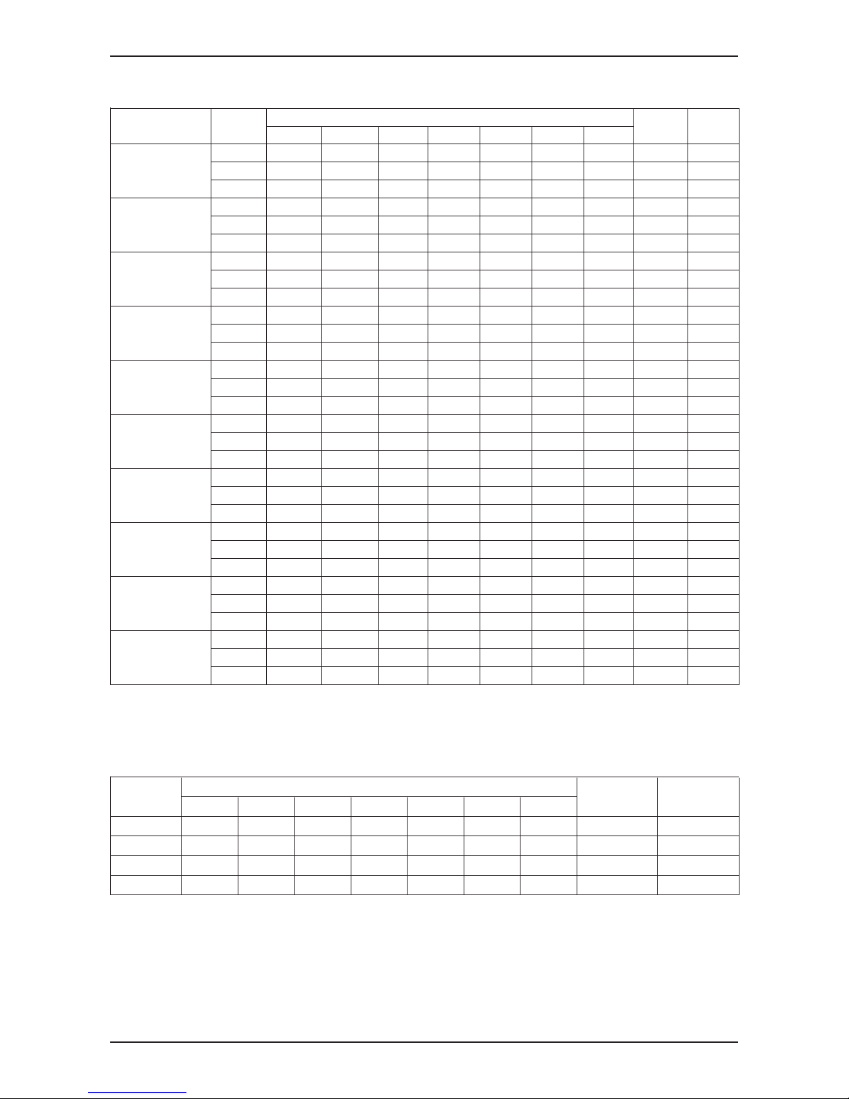
Heating Capacity Correction Factor
MCK020AWH - MCK050AWH
37.8 43.3 45 48.8 50 54.4 60 65.5 70
4.4 1.112 1.143 1.153 1.175 1.182 1.207 1.239 1.271 1.296
7.2 1.044 1.078 1.088 1.112 1.119 1.146 1.181 1.214 1.244
10.0 0.977 1.014 1.026 1.051 1.060 1.089 1.127 1.164 1.191
12.7 0.908 0.947 0.959 0.986 0.995 1.026 1.066 1.106 1.138
15.5 0.839 0.882 0.895 0.924 0.934 0.968 1.011 1.053 1.085
18.3 0.796 0.830 0.841 0.868 0.876 0.910 0.955 0.996 1.032
20.0 0.729 0.775 0.790 0.822 0.831 0.869 0.917 0.963 1.000
21.1 0.685 0.740 0.756 0.792 0.802 0.843 0.892 0.942 0.979
22.0 0.680 0.729 0.743 0.777 0.786 0.826 0.876 0.924 0.962
23.9 0.630 0.681 0.697 0.732 0.743 0.783 0.835 0.886 0.927
26.7 0.562 0.616 0.632 0.669 0.681 0.724 0.778 0.832 0.874
MCK020AW
37.8 43.3 45 48.8 50
4.4 1.256 1.343 1.370 1.431 1.450
7.2 1.175 1.265 1.293 1.355 1.374
10.0 1.087 1.179 1.207 1.271 1.291
12.7 1.004 1.142 1.127 1.192 1.213
15.5 0.917 1.014 1.044 1.110 1.132
18.3 0.849 0.939 0.968 1.033 1.054
20.0 0.777 0.877 0.909 0.978 1.000
21.1 0.730 0.837 0.870 0.943 0.965
22.0 0.716 0.822 0.850 0.920 0.943
23.9 0.657 0.761 0.793 0.865 0.887
26.7 0.572 0.678 0.711 0.784 0.807
MCK025AW
37.8 43.3 45 48.8 50
4.4 1.311 1.366 1.383 1.421 1.433
7.2 1.231 1.289 1.307 1.347 1.359
10.0 1.145 1.205 1.224 1.266 1.279
12.7 1.062 1.126 1.145 1.189 1.203
15.5 0.997 1.044 1.064 1.110 1.125
18.3 0.920 0.977 0.997 1.040 1.054
20.0 0.842 0.913 0.935 0.985 1.000
21.1 0.791 0.871 0.895 0.949 0.965
22.0 0.782 0.855 0.878 0.929 0.944
23.9 0.725 0.801 0.824 0.877 0.893
26.7 0.641 0.720 0.744 0.798 0.816
MCK030AW
37.8 43.3 45 48.8 50
4.4 1.344 1.380 1.390 1.415 1.422
7.2 1.263 1.301 1.312 1.339 1.347
10.0 1.182 1.224 1.237 1.266 1.275
12.7 1.098 1.143 1.156 1.187 1.197
15.5 1.015 1.064 1.079 1.112 1.123
18.3 0.962 1.000 1.014 1.044 1.054
20.0 0.880 0.934 0.951 0.988 1.000
21.1 0.828 0.892 0.911 0.952 0.965
22.0 0.822 0.878 0.895 0.934 0.946
23.9 0.766 0.825 0.843 0.884 0.897
26.7 0.685 0.747 0.766 0.809 0.823
EAT
˚C
EWT TEMP, ˚C
EWT TEMP, ˚C
EAT
˚C
EAT
˚C
EWT TEMP, ˚C
EAT
˚C
EWT TEMP, ˚C
Page 47

MFCU_(ii)
Fan Performance Chart
44
MCK040AW
37.8 43.3 45 48.8 50
4.4 1.330 1.373 13.860 1.416 1.425
7.2 1.249 1.295 1.309 1.340 1.350
10.0 1.165 1.214 1.229 1.263 1.274
12.7 1.086 1.138 1.154 1.190 1.202
15.5 1.000 1.055 1.073 1.111 1.123
18.3 0.948 0.993 1.008 1.043 1.054
20.0 0.867 0.928 0.946 0.988 1.000
21.1 0.815 0.885 0.906 0.952 0.965
22.0 0.809 0.871 0.890 0.934 0.946
23.9 0.749 0.815 0.835 0.880 0.894
26.7 0.668 0.737 0.758 0.806 0.821
MCK050AW
37.8 43.3 45 48.8 50
4.4 1.321 1.370 1.385 1.419 1.430
7.2 1.241 1.293 1.309 1.344 1.356
10.0 1.158 1.213 1.230 1.268 1.280
12.7 1.075 1.132 1.150 1.190 1.203
15.5 0.989 1.050 1.069 1.111 1.125
18.3 0.933 0.985 1.002 1.041 1.054
20.0 0.854 0.920 0.941 0.986 1.000
21.1 0.803 0.878 0.900 0.950 0.965
22.0 0.795 0.863 0.884 0.931 0.945
23.9 0.736 0.806 0.828 0.877 0.892
26.7 0.655 0.729 0.752 0.803 0.819
All other models
37.8 43.3 45 48.8 50
4.4 1.321 1.370 1.385 1.419 1.430
7.2 1.241 1.293 1.309 1.344 1.356
10.0 1.158 1.213 1.230 1.268 1.280
12.7 1.075 1.132 1.150 1.190 1.203
15.5 0.989 1.050 1.069 1.111 1.125
18.3 0.933 0.985 1.002 1.041 1.054
20.0 0.854 0.920 0.941 0.986 1.000
21.1 0.803 0.878 0.900 0.950 0.965
22.0 0.795 0.863 0.884 0.931 0.945
23.9 0.736 0.806 0.828 0.877 0.892
26.7 0.655 0.729 0.752 0.803 0.819
EAT
˚C
EWT TEMP, ˚C
EAT
˚C
EWT TEMP, ˚C
EAT
˚C
EWT TEMP, ˚C
Page 48

Engineering & Physical Data
MFCU_(ii)
45
Engineering & Physical Data
Engineeing Data - MWM-G2W
MWM007G2W
MWM010G2W
MWM015G2W
MWM020G2W
Btu/h
8000
9500
11000
15500
W
2340
2780
3220
4540
Btu/h
5900
6900
8000
12500
W
1730
2020
2350
3650
Btu/h
10300
12800
14000
20500
W
3020
3750
4100
6010
W
24
25
29
66
A
0.11
0.11
0.13
0.29
V/Ph/Hz
l/s / CFM
130 / 275
142 / 300
163 / 345
297 / 630
l/s / CFM
106 / 225
118 / 250
130 / 275
231 / 490
l/s / CFM
83 / 175
94 / 200
104 / 220
208 / 440
USGPM
1.76
2.11
2.42
3.43
litres/min
6.66
7.99
9.16
12.98
kPa/psi
48 / 7.0
65 / 9.4
77 / 11.1
50 / 7.3
kPa/psi
42 / 6.1
59 / 8.5
64 / 9.2
51 / 7.3
kPa/psi
1608 / 233
1608 / 233
1608 / 233
1608 / 233
m/s / ft/min
0.65 / 127.8
0.61 / 121.0
0.71 / 139.1
0.90 / 177.4
dBA
38 / 33 / 28
39 / 34 / 28
42 / 36 / 29
49 / 44 / 42
H X W X D
mm
260 X 799 X 198
260 X 899 X 198
260 X 899 X 198
304 X 1062 X 222
H X W X D
mm
330 X 827 X 265
330 X 927 X 265
330 X 927 X 265
378 X 1100 X 292
kg
8.5
9.4
9.4
15
mm
W
24
25
29
66
A
0.11
0.11
0.13
0.29
W
8
9
13
25
mm
m²
0.17
0.19
0.19
0.27
litre
0.49
0.57
0.57
0.85
pc
COLOUR
WHITE
2
CONNECTION
INDUCTION
TYPE
FAN MOTOR
COIL
WATER VOLUME
COPPER
WASHABLE SARANET FILTER
PACKING DIMENSION
UNIT DIMENSION
2
ROW
6.35
4
POLES
19.05
E
IPX0
MODEL
1/2" BSP FEMALE ADAPTOR
CROSS FLOW FAN
DIRECT
LCD WIRELESS MICRO-COMPUTER REMOTE CONTROL
POWER SOURCE
UNIT WEIGHT
DRIVE
NOMINAL COOLING CAPACITY
NOMINAL HEATING CAPACITY
(ENTERING WATER TEMP. = 50˚C)
INSULATION GRADE
RATED INPUT POWER
RATED RUNNING CURRENT
INDOOR UNIT
FAN
INDEX OF PROTECTION (IP)
CASING
NOMINAL RUNNING CURRENT
AIR DISCHARGE
220-240 / 1 / 50
LOW
MEDIUM
SOUND PRESSURE LEVEL (H/M/L)
AIR FLOW
SURFACE AIR VELOCITY
CONTROL
AUTOMATIC LOUVER (UP & DOWN)
PART NUMBER
TYPE
MOTOR OUTPUT
MATERIAL
FILTER
FIN
ALUMINIUM
QUANTITY
NOMINAL TOTAL INPUT POWER
OPERATION
HIGH
AIR
QUALITY
DIAMETER
MATERIAL
FACE AREA
TUBE
TYPE
CONDENSATE DRAIN SIZE
NOMINAL SENSIBLE COOLING CAPACITY
NOMINAL WATER FLOW RATE
HEAD LOSS (COOLING)
HEAD LOSS (HEATING) : 50˚C)
MAX. WORKING PRESSURE
00040011CZ07 00040011CZ15
00040011CZ10 00040011CZ20
HEATING
20°C DB
50°C (2 Pipes System)
70°C (4 Pipes System)
45°C (2 Pipes System)
60°C (4 Pipes System)
ALL SPECIFICATIONS ARE SUBJECTED TO CHANGE BY THE MANUFACTURER WITHOUT PRIOR NOTICE.
LEAVING WATER TEMPERATURE
MODE
27°C DB/ 19°C WB
7°C
COOLING
12°C
ENTERING AIR TEMPERATURE
ENTERING WATER TEMPERATURE
Page 49

MFCU_(ii)
Engineering & Physical Data
46
Engineeing Data - MWM-G2W
HEATING
20°C DB
50°C (2 Pipes System)
70°C (4 Pipes System)
45°C (2 Pipes System)
60°C (4 Pipes System)
ALL SPECIFICATIONS ARE SUBJECTED TO CHANGE BY THE MANUFACTURER WITHOUT PRIOR NOTICE.
LEAVING WATER TEMPERATURE
MODE
27°C DB/ 19°C WB
7°C
COOLING
12°C
ENTERING AIR TEMPERATURE
ENTERING WATER TEMPERATURE
00040011CZ25
00040011CZ301
MWM025G2W
MWM301GW
Btu/h
18000
22000
W
5280
6450
Btu/h
14800
16720
W
4330
4900
Btu/h
23000
23000
W
6740
6740
W
69
74
A
0.30
0.32
V/Ph/Hz
l/s / CFM
312 / 660
316 / 670
l/s / CFM
274 / 580
297 / 630
l/s / CFM
222 / 470
236 / 500
USGPM
4.00
4.90
litres/min
15.14
18.50
kPa/psi
69 / 10
52 / 7.6
kPa/psi
71 / 10.2
19 / 2.7
kPa/psi
1608 / 233
1608 / 233
m/s / ft/min
0.94 / 185.9
1.09 / 214.7
dBA
50 / 48 / 45
49 / 47 / 45
H X W X D
mm
304 X 1062 X 222
360 X 1200 X 200
H X W X D
mm
378 X 1100 X 292
760 X 1311 X 301
kg
15
17.6
mm
W
69
74
A
0.30
0.32
W
38
40
mm
6.35
9.53
m²
0.27
0.29
litre
0.85
1.43
pc
COLOUR
WHITE
LIGHT GREY
NOMINAL RUNNING CURRENT
MODEL
NOMINAL COOLING CAPACITY
NOMINAL SENSIBLE COOLING CAPACITY
NOMINAL HEATING CAPACITY
(ENTERING WATER TEMP. = 50˚C)
NOMINAL TOTAL INPUT POWER
POWER SOURCE
220-240 / 1 / 50
INDOOR UNIT
CONTROL
AIR DISCHARGE
AUTOMATIC LOUVER (UP & DOWN)
OPERATION
LCD WIRELESS MICRO-COMP REMOTE CTRL
AIR FLOW
HIGH
MEDIUM
LOW
NOMINAL WATER FLOW RATE
HEAD LOSS (COOLING)
HEAD LOSS (HEATING) : 50˚C)
MAX. WORKING PRESSURE
SURFACE AIR VELOCITY
SOUND PRESSURE LEVEL (H/M/L)
UNIT DIMENSION
PACKING DIMENSION
UNIT WEIGHT
CONDENSATE DRAIN SIZE
19.05
CONNECTION
1/2" BSP FEMALE ADAPTOR
FAN
TYPE
CROSS FLOW FAN
DRIVE
DIRECT
FAN
MOTOR
TYPE
INDUCTION
INDEX OF PROTECTION (IP)
INSULATION GRADE
B
RATED INPUT POWER
RATED RUNNING CURRENT
MOTOR OUTPUT
POLES
4
COIL
TUBE
MATERIAL
COPPER
DIAMETER
FIN
MATERIAL
ALUMINIUM
FACE AREA
2
WATER VOLUME
AIR
QUALITY
FILTER
TYPE
WASHABLE SARANET FILTER
QUANTITY
2
IPX0
CASING
PART NUMBER
ROW
Page 50

Engineering & Physical Data
MFCU_(ii)
47
HEATING
20°C DB
50°C (2 Pipes System)
70°C (4 Pipes System)
45°C (2 Pipes System)
60°C (4 Pipes System)
ALL SPECIFICATIONS ARE SUBJECTED TO CHANGE BY THE MANUFACTURER WITHOUT PRIOR NOTICE.
LEAVING WATER TEMPERATURE
MODE
27°C DB/ 19°C WB
7°C
COOLING
12°C
ENTERING AIR TEMPERATURE
ENTERING WATER TEMPERATURE
Engineeing Data - MCK-AW
MCK020AW
MCK025AW
MCK030AW
MCK040AW
MCK050AW
Btu/h
22500
25500
30000
33500
36500
W
6620
7500
8800
9820
10800
Btu/h
16700
18400
21800
24200
26300
W
4900
5400
6400
7100
7700
Btu/h
28500
32000
37500
40500
44000
W
8400
9500
11000
11870
12900
W
127
151
164
192
253
A
0.52
0.64
0.68
0.79
1.06
V/Ph/Hz
l/s / CFM
364 / 771
383 / 812
433 / 918
483 / 1024
511 / 1083
l/s / CFM
314 / 665
328 / 695
367 / 777
425 / 901
467 / 989
l/s / CFM
297 / 630
297 / 630
336 / 712
372 / 789
428 / 906
USGPM
5.02
5.68
6.65
7.53
8.19
litres/min
19.00
21.55
25.23
28.52
30.97
kPa/psi
25 / 3.6
31 / 4.5
42 / 6.0
52 / 7.6
69 / 10.0
kPa/psi
21 / 3.1
27 / 3.9
35 / 5.1
45 / 6.6
64 / 9.3
kPa/psi
1608 / 233
1608 / 233
1608 / 233
1608 / 233
1608 / 233
m/s / ft/min
0.78 / 153.6
0.82 / 161.8
0.93 / 182.9
1.04 / 204.0
1.10 / 215.7
dBA
42 / 39 / 37
45 / 42 / 40
49 / 45 / 43
51 / 48 / 46
53 / 52 / 50
H X W X D
mm
H X W X D
mm
kg
25 + 4
36 + 4
38 + 4
42 + 4
44 + 4
mm
W
127
151
164
192
253
A
0.52
0.64
0.68
0.79
1.06
W
35
45
60
83
120
mm
m²
litre
pc
COLOUR
RATED RUNNING CURRENT
CASING
LIGHT GREY
PART NUMBER
WATER VOLUME
2.69
9.53
MATERIAL
ALUMINIUM
FACE AREA
305 X 824 X 824 (355 X 930 X930)
371 X 916 X 916 (121 X 1000 X 1016)
UNIT DIMENSION - ( ) WITH PANEL
PACKING DIMENSION - ( ) PANEL
RATED INPUT POWER
TUBE
MATERIAL
COPPER
DIAMETER
COIL
0.47
ROW
2
AIR
QUALITY
FILTER
TYPE
WASHABLE SARANET FILTER
QUANTITY
1
FIN
MOTOR OUTPUT
POLES
8
FAN
TYPE
TURBO FAN
DRIVE
DIRECT
FAN
MOTOR
TYPE
INDUCTION
INDEX OF PROTECTION (IP)
INSULATION GRADE
UNIT WEIGHT (UNIT + PANEL)
CONDENSATE DRAIN SIZE
CONNECTION
3/4" BSP FEMALE UNION
19.05
B
IP22
HEAD LOSS (HEATING) : 50˚C)
MAX. WORKING PRESSURE
SURFACE AIR VELOCITY
SOUND PRESSURE LEVEL (H/M/L)
LCD WIRELESS MICRO-COMPUTER REMOTE CONTROL
AIR FLOW
HIGH
MEDIUM
LOW
POWER SOURCE
220-240 / 1 / 50
INDOOR UNIT
CONTROL
AIR DISCHARGE
4 WAY AUTOMATIC LOUVER (UP & DOWN)
HEAD LOSS (COOLING)
OPERATION
MODEL
NOMINAL COOLING CAPACITY
NOMINAL SENSIBLE COOLING CAPACITY
NOMINAL HEATING CAPACITY
(ENTERING WATER TEMP. = 50˚C)
NOMINAL TOTAL INPUT POWER
NOMINAL RUNNING CURRENT
NOMINAL WATER FLOW RATE
00040011DA20
00040011DA25
00040011DA30
00040011DA40 00040011DA50
Page 51

MFCU_(ii)
Engineering & Physical Data
48
Engineeing Data - MCK-AWH
MCK020AWH
MCK025AWH
MCK030AWH
MCK040AWH
MCK050AWH
Btu/h
13000
13500
15500
17100
17500
W
3810
3960
4540
4980
5130
Btu/h
11600
12000
13850
13340
15500
W
3400
3520
4060
4400
4540
Btu/h
36000
37500
42500
45500
46500
W
10550
10990
12460
13480
13770
W
122
138
153
184
232
A
0.53
0.61
0.67
0.80
1.02
V/Ph/Hz
l/s / CFM
364 / 771
383 / 812
433 / 918
484 / 1024
511 / 1083
l/s / CFM
314 / 665
328 / 695
367 / 777
425 / 901
467 / 989
l/s / CFM
297 / 630
297 / 630
336 / 712
372 / 789
428 / 906
USGPM
2.90
3.00
3.52
3.80
3.92
litres/min
10.92
11.35
13.27
14.37
14.80
USGPM
4.00
4.18
4.76
5.10
5.20
litres/min
15.12
15.75
17.93
19.32
19.73
kPa/psi
4 / 0.5
4 / 0.5
5 / 0.7
6 / 0.8
6 / 0.9
kPa/psi
5 / 0.7
6 / 0.8
7 / 1.0
9 / 1.2
9 / 1.3
kPa/psi
1608 / 233
1608 / 233
1608 / 233
1608 / 233
1608 / 233
m/s / ft/min
0.78 / 153.6
0.82 / 161.8
0.93 / 182.9
1.04 / 204.0
1.10 / 215.7
dBA
42 / 39 / 37
45 / 42 / 40
49 / 45 / 43
51 / 48 / 46
53 / 52 / 50
H X W X D
mm
H X W X D
mm
kg
25 + 4
36 + 4
38 + 4
42 + 4
44 + 4
mm
W
122
138
153
184
232
A
0.53
0.61
0.67
0.8
1.02
W
35
45
60
83
120
mm
m²
litre
pc
COLOUR
MODEL
NOMINAL COOLING CAPACITY
NOMINAL SENSIBLE COOLING CAPACITY
NOMINAL HEATING CAPACITY
(ENTERING WATER TEMP. = 50˚C)
NOMINAL TOTAL INPUT POWER
NOMINAL RUNNING CURRENT
POWER SOURCE
220-240 / 1 / 50
INDOOR UNIT
CONTROL
AIR DISCHARGE
4 WAY AUTOMATIC LOUVER (UP & DOWN)
OPERATION
LCD WIRELESS MICRO-COMPUTER REMOTE CONTROL
AIR FLOW
HIGH
MEDIUM
LOW
NOMINAL WATER FLOW RATE
(COOLING)
NOMINAL WATER FLOW RATE
(HEATING) : 70˚C
HEAD LOSS (COOLING)
HEAD LOSS (HEATING) : 70˚C
MAX. WORKING PRESSURE
SURFACE AIR VELOCITY
SOUND PRESSURE LEVEL (H/M/L)
UNIT DIMENSION - ( ) WITH PANEL
305 X 824 X 824 (355 X 930 X 930)
PACKING DIMENSION - ( ) PANEL
371 X 916 X 916 (121 X 1000 X 1016)
UNIT WEIGHT
CONDENSATE DRAIN SIZE
19.05
CONNECTION
3/4" BSP FEMALE UNION
FAN
TYPE
TURBO FAN
DRIVE
DIRECT
FAN
MOTOR
TYPE
INDUCTION
INDEX OF PROTECTION (IP)
INSULATION GRADE
B
RATED INPUT POWER
RATED RUNNING CURRENT
MOTOR OUTPUT
POLES
8
COIL
TUBE
MATERIAL
COPPER
DIAMETER
9.53
FIN
MATERIAL
ALUMINIUM
FACE AREA
0.47
ROW
2
WATER VOLUME
1.34
AIR
QUALITY
FILTER
TYPE
WASHABLE SARANET FILTER
QUANTITY
1
IP22
CASING
LIGHT GREY
PART NUMBER
HEATING
20°C DB
50°C (2 Pipes System)
70°C (4 Pipes System)
45°C (2 Pipes System)
60°C (4 Pipes System)
ALL SPECIFICATIONS ARE SUBJECTED TO CHANGE BY THE MANUFACTURER WITHOUT PRIOR NOTICE.
LEAVING WATER TEMPERATURE
MODE
27°C DB/ 19°C WB
7°C
COOLING
12°C
ENTERING AIR TEMPERATURE
ENTERING WATER TEMPERATURE
00040011DB20 00040011DB25 00040011DB30
00040011DB40
00040011DB50
Page 52

Engineering & Physical Data
MFCU_(ii)
49
HEATING
20°C DB
50°C (2 Pipes System)
70°C (4 Pipes System)
45°C (2 Pipes System)
60°C (4 Pipes System)
ALL SPECIFICATIONS ARE SUBJECTED TO CHANGE BY THE MANUFACTURER WITHOUT PRIOR NOTICE.
LEAVING WATER TEMPERATURE
MODE
27°C DB/ 19°C WB
7°C
COOLING
12°C
ENTERING AIR TEMPERATURE
ENTERING WATER TEMPERATURE
MCK010CW
MCK015CW
MCK020CW
Btu/h
8500
14000
15500
W
2490
4100
4540
Btu/h
6500
10000
11500
W
1910
2930
3370
Btu/h
12000
16000
18000
W
3520
4690
5280
W
63
64
79
A
0.28
0.28
0.35
V/Ph/Hz
l/s / CFM
179 / 380
189 / 400
208 / 404
l/s / CFM
137 / 290
146 / 310
156 / 330
l/s / CFM
109 / 230
104 / 220
132 / 280
USGPM
2.03
3.43
3.57
litres/min
7.67
13.00
13.50
kPa/psi
19 / 2.8
27 / 3.9
29 / 4.3
kPa/psi
17 / 2.5
24 / 3.5
27 / 4.0
kPa/psi
1608 / 233
1608 / 233
1608 / 233
m/s / ft/min
0.77 / 151.0
0.60 / 118.1
0.66 / 130.2
dBA
42 / 35 / 29
45 / 38 / 30
48 / 40 / 36
H X W X D
mm
H X W X D
mm
kg
16 + 2
18 + 2
18 + 2
mm
W
63
64
79
A
0.22
0.30
0.34
W
16
18
22
mm
m²
0.24
0.25
0.25
1
2
2
litre
0.56
1.15
1.15
pc
COLOUR
3/4" BSP FEMALE ADAPTOR
19.05
250 X 570 X 570 (295 X 640 X 640)
317 X 630 X 630 (127 X 700 X 726)
TURBO FAN
220-240 / 1 / 50
LCD WIRELESS MICRO-COMPUTER REMOTE CONTROL
4 WAY AUTOMATIC LOUVER (UP & DOWN)
LIGHT GREY
1
WASHABLE SARANET FILTER
ALUMINIUM
B
INDUCTION
DIRECT
PART NUMBER
WATER VOLUME
AIR
QUALITY
FILTER
TYPE
CASING
QUANTITY
COIL
TUBE
POLES
6
COPPER
MATERIAL
DIAMETER
FIN
MATERIAL
FACE AREA
ROW
FAN
TYPE
DRIVE
FAN MOTOR
TYPE
INDEX OF PROTECTION (IP)
INSULATION GRADE
RATED INPUT POWER
RATED RUNNING CURRENT
MOTOR OUTPUT
CONDENSATE DRAIN SIZE
CONNECTION
HEAD LOSS (COOLING)
HEAD LOSS (HEATING) : 50˚C
MAX. WORKING PRESSURE
SURFACE AIR VELOCITY
SOUND PRESSURE LEVEL (H/M/L)
UNIT DIMENSION - ( ) WITH PANEL
UNIT WEIGHT
MODEL
NOMINAL COOLING CAPACITY
NOMINAL SENSIBLE COOLING CAPACITY
NOMINAL HEATING CAPACITY
(ENTERING WATER TEMP. = 50˚C)
NOMINAL TOTAL INPUT POWER
AIR FLOW
HIGH
MEDIUM
LOW
POWER SOURCE
NOMINAL RUNNING CURRENT
INDOOR UNIT
CONTROL
AIR DISCHARGE
OPERATION
NOMINAL WATER FLOW RATE
PACKING DIMENSION - ( ) PANEL
IP20
7.00
Engineeing Data - MCK-CW
00040011DC15
00040011DC20
00040011DC10
Page 53

MFCU_(ii)
Engineering & Physical Data
50
HEATING
20°C DB
50°C (2 Pipes System)
70°C (4 Pipes System)
45°C (2 Pipes System)
60°C (4 Pipes System)
ALL SPECIFICATIONS ARE SUBJECTED TO CHANGE BY THE MANUFACTURER WITHOUT PRIOR NOTICE.
LEAVING WATER TEMPERATURE
MODE
27°C DB/ 19°C WB
7°C
COOLING
12°C
ENTERING AIR TEMPERATURE
ENTERING WATER TEMPERATURE
Engineeing Data - MCM-EW
MCM015EW
MCM020EW
MCM025EW
Btu/h
15500
20300
21000
W
4540
5950
6150
Btu/h
12700
15400
16200
W
3720
4510
4750
Btu/h
19500
25000
28000
W
5720
7330
8210
W
101
109
113
A
0.46
0.49
0.52
V/Ph/Hz
l/s / CFM
236 / 500
274 / 580
293 / 620
l/s / CFM
213 / 450
250 / 530
269 / 570
l/s / CFM
189 / 400
231 / 490
245 / 520
USGPM
3.43
4.49
4.67
litres/min
12.98
17.00
17.68
kPa/psi
27 / 4.0
48 / 7.0
57 / 8.3
kPa/psi
24 / 3.5
42 / 6.1
50 / 7.3
kPa/psi
1608 / 233
1608 / 233
1608 / 233
m/s / ft/min
0.72 / 140.9
0.83 / 163.3
1.54 / 302.3
dBA
50 / 43 / 41
53 / 51 / 49
56 / 51 / 44
H X W X D
mm
H X W X D
mm
kg
mm
W
101
109
113
A
0.46
0.49
0.52
W
50
65
70
mm
m²
litre
pc
COLOUR
NOMINAL SENSIBLE COOLING CAPACITY
MODEL
NOMINAL COOLING CAPACITY
AIR FLOW
HIGH
MEDIUM
LOW
NOMINAL HEATING CAPACITY
(ENTERING WATER TEMP. = 50˚C)
NOMINAL TOTAL INPUT POWER
NOMINAL RUNNING CURRENT
POWER SOURCE
UNIT DIMENSION
212 X 1090 X 630
PACKING DIMENSION
297 X 1197 X 740
NOMINAL WATER FLOW RATE
HEAD LOSS (COOLING)
HEAD LOSS (HEATING) : 50˚C
MAX. WORKING PRESSURE
SURFACE AIR VELOCITY
SOUND PRESSURE LEVEL (H/M/L)
UNIT WEIGHT
CONDENSATE DRAIN SIZE
CONNECTION
FAN
TYPE
DRIVE
FIN
MATERIAL
FAN MOTOR
TYPE
INDEX OF PROTECTION (IP)
INSULATION GRADE
RATED INPUT POWER
RATED RUNNING CURRENT
MOTOR OUTPUT
POLES
ROW
3
WATER VOLUME
AIR QUALITY
FILTER
TYPE
QUANTITY
COIL
TUBE
MATERIAL
2
CASING
PART NUMBER
INDOOR UNIT
CONTROL
AIR DISCHARGE
OPERATION
FACE AREA
4
COPPER
IP22
B
DIRECT
INDUCTION
DIAMETER
CROSS FLOW FAN
LIGHT GREY
6.35
1.11
ALUMINIUM
0.33
WASHABLE SARANET FILTER
AUTOMATIC LOUVER (UP & DOWN)
LCD WIRELESS MICRO-COMPUTER REMOTE CONTROL
27
19.05
1/2" BSP FEMALE ADAPTOR
220-240 / 1 / 50
00040011DF20
00040011DF15 00040011DF25
Page 54

Engineering & Physical Data
MFCU_(ii)
51
HEATING
20°C DB
50°C (2 Pipes System)
70°C (4 Pipes System)
45°C (2 Pipes System)
60°C (4 Pipes System)
ALL SPECIFICATIONS ARE SUBJECTED TO CHANGE BY THE MANUFACTURER WITHOUT PRIOR NOTICE.
LEAVING WATER TEMPERATURE
MODE
27°C DB/ 19°C WB
7°C
COOLING
12°C
ENTERING AIR TEMPERATURE
ENTERING WATER TEMPERATURE
Engineeing Data - MCM-DW
MCM020DW
MCM025DW
MCM030DW
MCM040DW MCM050DW
Btu/h
17700
20800
24600
31200 45000
W
5190
6100
7210
9140 13190
Btu/h
13700
15000
17700
25600 31400
W
4000
4400
5190
7500 9200
Btu/h
22000
25900
28000
42300 51500
W
6450
7590
8210
12400 15090
W
96
130
132
240 240
A
0.41
0.54
0.57
0.98 1.03
V/Ph/Hz
l/s / CFM
264 / 560
297 / 630
329 / 697
451 / 956 500 / 1059
l/s / CFM
238 / 505
293 / 620
324 / 687
428 / 908 483 / 1023
l/s / CFM
189 / 400
262 / 555
307 / 650
419 / 889 451 / 956
USGPM
3.92
4.62
5.46
6.91 9.99
litres/min
14.84
17.49
20.67
26.16 37.82
kPa/psi
46 / 6.6
56 / 8.1
49 / 7.2
24 / 3.5 38 / 5.5
kPa/psi
39 / 5.7
48 / 7.0
43 / 6.2
22 / 3.1 32 / 4.6
kPa/psi
1608 / 233
1608 / 233
1608 / 233
1608 / 233 1608 / 233
m/s / ft/min
1.39 / 273.0
1.56 / 307.2
1.37 270.3
1.22 / 240.2 1.35 / 266.2
dBA
50 / 47 / 40
54 / 53 / 50
51 / 50 / 48
54 / 53 / 52 54 / 53 / 52
H X W X D
mm
H X W X D
mm
kg
43
43
45
70 70
mm
W
96
130
132
240 240
A
0.41
0.54
0.57
0.98 1.03
W
40
65
65
100 120
mm
m²
0.19
0.19
0.24
0.37 0.37
litre
1.68
1.68
2.09
4.25 4.25
pc
2 + 1 2 + 3
COLOUR
354 X 1876 X 766
249 X 1714 X 670
3
4
2
WASHABLE SARANET FILTER
B
IP22
PART NUMBER
301 X 1311 X 760
CASING
AIR
QUALITY
FILTER
TYPE
QUANTITY
LIGHT GREY
FACE AREA
ROW
4
COIL
TUBE
MATERIAL
COPPER
DIAMETER
WATER VOLUME
9.53
FIN
MATERIAL
ALUMINIUM
FAN MOTOR
TYPE
INDUCTION
INDEX OF PROTECTION (IP)
INSULATION GRADE
RATED RUNNING CURRENT
MOTOR OUTPUT
POLES
CONNECTION
3/4" BSP FEMALE UNION
FAN
TYPE
BLOWER
DRIVE
DIRECT
PACKING DIMENSION
UNIT WEIGHT
CONDENSATE DRAIN SIZE
19.05
HEAD LOSS (COOLING)
HEAD LOSS (HEATING) : 50˚C
MAX. WORKING PRESSURE
SURFACE AIR VELOCITY
SOUND PRESSURE LEVEL (H/M/L)
214 X 1214 X 670
LCD WIRELESS MICRO-COMPUTER REMOTE CONTROL
AIR FLOW
HIGH
MEDIUM
LOW
NOMINAL WATER FLOW RATE
220-240 / 1 / 50
INDOOR UNIT
CONTROL
AIR DISCHARGE
AUTOMATIC LOUVER (UP & DOWN)
OPERATION
UNIT DIMENSION
MODEL
NOMINAL COOLING CAPACITY
NOMINAL SENSIBLE COOLING CAPACITY
NOMINAL HEATING CAPACITY
(ENTERING WATER TEMP. = 50˚C)
NOMINAL TOTAL INPUT POWER
NOMINAL RUNNING CURRENT
POWER SOURCE
RATED INPUT POWER
00040011DD20 00040011DD25 00040011DD30 00040011DD40 00040011DD50
Page 55

MFCU_(ii)
Engineering & Physical Data
52
HEATING
20°C DB
50°C (2 Pipes System)
70°C (4 Pipes System)
45°C (2 Pipes System)
60°C (4 Pipes System)
ALL SPECIFICATIONS ARE SUBJECTED TO CHANGE BY THE MANUFACTURER WITHOUT PRIOR NOTICE.
LEAVING WATER TEMPERATURE
MODE
27°C DB/ 19°C WB
7°C
COOLING
12°C
ENTERING AIR TEMPERATURE
ENTERING WATER TEMPERATURE
Engineeing Data - MCM-CBW
MCM007CBW
MCM010CBW
MCM015CBW
Btu/h
6500
8500
10500
W
1910
2490
3080
Btu/h
5000
6700
8600
W
1460
1960
2520
Btu/h
7500
10500
14200
W
2280
3080
4250
W
49
50
81
A
0.22
0.22
0.35
V/Ph/Hz
l/s / CFM
94 / 200
142 / 300
190 / 400
l/s / CFM
80 / 170
134 / 280
156 / 330
l/s / CFM
71 / 150
119 / 250
139 / 292
USGPM
1.45
1.89
2.33
litres/min
5.49
7.15
8.82
kPa/psi
9 / 1.4
15 / 2.2
5 / 0.7
kPa/psi
7 / 1.01
13 / 1.8
4 / 0.5
kPa/psi
1608 / 233
1608 / 233
1608 / 233
m/s / ft/min
0.79 / 155.1
1.18 / 232.7
0.99 / 195.2
dBA
45 / 42 / 37
46 / 43 / 38
47 / 44 / 39
H X W X D
mm
235 X 666 X 1174
H X W X D
mm
301 X 757 X 1286
kg
33
33
35
mm
W
49
50
81
A
0.22
0.22
0.35
W
47
52
75
mm
m²
0.12
0.12
0.19
litre
0.70
0.70
1.1
pc
COLOUR
NOMINAL SENSIBLE COOLING CAPACITY
NOMINAL HEATING CAPACITY
(ENTERING WATER TEMP. = 50˚C)
NOMINAL TOTAL INPUT POWER
NOMINAL RUNNING CURRENT
MODEL
NOMINAL COOLING CAPACITY
POWER SOURCE 220-240 / 1 / 50
INDOOR UNIT
CONTROL
AIR DISCHARGE AUTOMATIC LOUVER (UP & DOWN)
OPERATION LCD WIRELESS MICRO-COMPUTER REMOTE CONTROL
AIR FLOW
HIGH
MEDIUM
LOW
NOMINAL WATER FLOW RATE
HEAD LOSS (COOLING)
HEAD LOSS (HEATING) : 50˚C
MAX. WORKING PRESSURE
SURFACE AIR VELOCITY
SOUND PRESSURE LEVEL (H/M/L)
UNIT DIMENSION 235 X 666 X 824
PACKING DIMENSION 301 X 757 X 936
UNIT WEIGHT
CONDENSATE DRAIN SIZE 19.05
CONNECTION 3/4" BSP FEMALE ADAPTOR
FAN
TYPE BLOWER
DRIVE DIRECT
FAN MOTOR
TYPE INDUCTION
IP22
INDEX OF PROTECTION (IP)
INSULATION GRADE B
RATED INPUT POWER
RATED RUNNING CURRENT
MOTOR OUTPUT
POLES 6
MATERIAL COPPER
DIAMETER 9.53
FIN
MATERIAL ALUMINIUM
FACE AREA
ROW
WATER VOLUME
AIR QUALITY FILTER
TYPE WASHABLE SARANET FILTER
QUANTITY 2
COIL
TUBE
2
CASING LIGHT GREY
PART NUMBER
00040011DE07
00040011DE15
00040011DE10
Page 56

Engineering & Physical Data
MFCU_(ii)
53
Engineeing Data - MCC-CW
HEATING
20°C DB
50°C (2 Pipes System)
70°C (4 Pipes System)
45°C (2 Pipes System)
60°C (4 Pipes System)
ALL SPECIFICATIONS ARE SUBJECTED TO CHANGE BY THE MANUFACTURER WITHOUT PRIOR NOTICE.
LEAVING WATER TEMPERATURE
MODE
27°C DB/ 19°C WB
7°C
COOLING
12°C
ENTERING AIR TEMPERATURE
ENTERING WATER TEMPERATURE
MCC010CW MCC015CW MCC020CW MCC025CW MCC028CW
Btu/h
9900 11600 18000 22500 24600
W
2900 3400 5280 6590 7210
Btu/h
7000 8100 12600 15800 17090
W
2050 2370 3690 4620 5009
Btu/h
11500 15000 23000 29000 30900
W
3370 4400 6740 8500 9056
W
68 97 141 165 150
A
0.30 0.42 0.64 0.73 0.62
V/Ph/Hz
l/s / CFM
142 / 300 241 / 510 330 / 700 344 / 730 382 / 810
l/s / CFM
123 / 260 208 / 440 321 / 680 340 / 720 363 / 770
l/s / CFM
104 / 220 170 / 360 293 / 620 274 / 580 335 / 710
mmAq
5 / 4 / 3 5 / 4 / 2 7 / 6 / 3 6 / 4 / 3 8 / 7 / 6
USGPM
2.20 2.55 4.00 4.98 5.73
litres/min
8.33 9.65 15.14 18.85 21.7
kPa/psi
11 / 1.5 24 / 3.5 20 / 2.9 32 / 4.7 24 / 3.5
kPa/psi
9 / 1.3 20 / 2.9 17 / 2.5 28 / 4 22 / 3.2
kPa/psi
m/s / ft/min
1.29 / 254.4 1.73 / 339.8 1.83 / 360.7 1.72 / 339.5 1.59 / 313.9
dBA
33 / 30 / 26 37 / 34 / 29 38 / 36 / 34 40 / 39 / 36 41 / 38 / 34
H X W X D
mm
261 x 765 x 411 261 / 905 / 411
261 x 1065 x 411 261 x 1200 x 411 285 x 992 x 600
H X W X D
mm
376 x 951 x 541
376 x 1090 x 541 376 x 1251 x 541 376 x 1386 x 541 343 x 1138 x 690
kg
18 24 27 28 39
mm
W
68 97 141 165 150
A
0.30 0.42 0.64 0.73 0.62
W
30 46 78 86 98
mm
m²
0.11 0.14 0.18 0.2 0.24
litre
1.03 1.27 1.55 1.78 2.03
1 1 1 1 2
COLOUR
00040011DG10 00040011DG15 00040011DG20 00040011DG25 00040011DG28
1600 / 232
EXTERNAL STATIC PRESSURE (H/M/L)
19.05
CASING LIGHT GREY
PART NUMBER
WATER VOLUME
AIR
QUALITY
FILTER
TYPE WASHABLE SARANET
QUANTITY
COIL
DIAMETER
ALUMINIUM
FACE AREA
ROW 3
FIN
MATERIAL
POLES 4
TUBE
MATERIAL COPPER
9.53
FAN
MOTOR
TYPE INDUCTION
INDEX OF PROTECTION (IP) IP22
INSULATION GRADE B
RATED INPUT POWER
RATED RUNNING CURRENT
MOTOR OUTPUT
SOUND PRESSURE LEVEL (H/M/L)
UNIT DIMENSION
CONNECTION 3/4" BSP FEMALE ADAPTOR
FAN
TYPE CENTRIFUGAL
DRIVE DIRECT
MEDIUM
LOW
NOMINAL WATER FLOW RATE
PACKING DIMENSION
UNIT WEIGHT
CONDENSATE DRAIN SIZE
HEAD LOSS (COOLING)
HEAD LOSS (HEATING) : 50˚C
MAX. WORKING PRESSURE
SURFACE AIR VELOCITY
POWER SOURCE 220-240 / 1 / 50
INDOOR UNIT
CONTROL
AIR DISCHARGE DUCTED
OPERATION SLM WIRED HANDSET
AIR FLOW
HIGH
MODEL
NOMINAL COOLING CAPACITY
NOMINAL SENSIBLE COOLING CAPACITY
NOMINAL HEATING CAPACITY
(ENTERING WATER TEMP. = 50˚C)
NOMINAL TOTAL INPUT POWER
NOMINAL RUNNING CURRENT
Page 57

MFCU_(ii)
Engineering & Physical Data
54
Engineeing Data - MCC-CW (Cont’d)
HEATING
20°C DB
50°C (2 Pipes System)
70°C (4 Pipes System)
45°C (2 Pipes System)
60°C (4 Pipes System)
ALL SPECIFICATIONS ARE SUBJECTED TO CHANGE BY THE MANUFACTURER WITHOUT PRIOR NOTICE.
LEAVING WATER TEMPERATURE
MODE
27°C DB/ 19°C WB
7°C
COOLING
12°C
ENTERING AIR TEMPERATURE
ENTERING WATER TEMPERATURE
MCC030CW
MCC038CW MCC040CW
MCC050CW
MCC060CW
Btu/h
26500
32200 30000
44560
51200
W
7770
9440 8790
13060
15010
Btu/h
18700
23900 21000
31250
35860
W
5480
7010 6160
9160
10510
Btu/h
33700
42600 42200
53700
62800
W
9880
12490 12370
15740
18410
W
345
423 373
427
531
A
1.69
1.76 1.88
2.13
2.34
V/Ph/Hz
l/s / CFM
392 / 830
548 / 1160 458 / 970
652 / 1380
723 / 1530
l/s / CFM
359 / 760
487 / 1030 449 / 950
605 / 1280
675 / 1430
l/s / CFM
335 / 710
435 / 920 406 / 860
572 / 1210
609 / 1290
USGPM
6.18
7.51 6.99
10.39
11.93
litres/min
23.38
28.41 26.47
39.32
45.17
kPa/psi
15 / 2.1
32.2 / 4.7 21 / 3
41 / 5.9
38.3 / 5.6
kPa/psi
12 / 1.8
30 / 4.4 18 / 2.6
36 / 5.2
34.8 / 5.1
kPa/psi
m/s / ft/min
1.40 / 275.7
2.04 / 401.7 1.57 / 308.1
1.59 / 313.0
1.51 / 296.5
dBA
46 / 42 / 38
51 / 48 / 45 49 / 45 / 41
52 / 50 / 47
53 / 50 / 47
H X W X D
mm
378 x 990 x 541
315 x 1297 x 638 378 x 1106 x 541
378 x 1358 x 541
378 x 1558 x 541
H X W X D
mm
415 x 1126 x 631
355 x 1461 x 727 415 x 1245 x 631
415 x 1297 x 631
415 x 1701 x 631
kg
42
50 45
49
57
mm
W
345
423 373
427
531
A
1.69
1.76 1.88
2.13
2.34
W
224
231 285
306
384
mm
m²
0.28
0.34 0.32
0.41
0.48
litre
2.45
2.94 2.8
3.56
4.16
pc
COLOUR
NOMINAL SENSIBLE
COOLING CAPACITY
NOMINAL HEATING CAPACITY
(ENTERING WATER TEMP. = 50˚C)
MODEL
NOMINAL COOLING CAPACITY
NOMINAL TOTAL INPUT POWER
NOMINAL RUNNING CURRENT
POWER SOURCE 220-240 / 1 / 50
CONTROL
AIR DISCHARGE DUCTED
OPERATION SLM WIRED HANDSET
AIR FLOW
HIGH
MEDIUM
LOW
NOMINAL WATER FLOW RATE
HEAD LOSS (COOLING)
HEAD LOSS (HEATING) : 50˚C
MAX. WORKING PRESSURE 1600 / 232
SURFACE AIR VELOCITY
SOUND PRESSURE LEVEL (H/M/L)
UNIT DIMENSION
PACKING DIMENSION
UNIT WEIGHT
CONDENSATE DRAIN SIZE 19.05
MOTOR OUTPUT
CONNECTION 3/4" BSP FEMALE ADAPTOR
FAN
TYPE CENTRIFUGAL
DRIVE DIRECT
MATERIAL
FAN
MOTOR
TYPE INDUCTION
INDEX OF PROTECTION (IP) IP22
INSULATION GRADE B
RATED INPUT POWER
RATED RUNNING CURRENT
QUANTITY
POLES 4
COIL
TUBE
MATERIAL COPPER
DIAMETER 9.53
FIN
INDOOR UNIT
ALUMINIUM
FACE AREA
ROW 3
WATER VOLUME
AIR
QUALITY
FILTER
TYPE WASHABLE SARANET
2
CASING LIGHT GREY
PART NUMBER
00040011DG30 00040011DG38 00040011DG40
00040011DG50
00040011DG60
mmAq
17 / 13 / 9 12 / 11 / 9 18 / 13 / 10 16 / 14 / 11 16 / 14 / 10
EXTERNAL STATIC PRESSURE (H/M/L)
Page 58

Engineering & Physical Data
MFCU_(ii)
55
Engineeing Data - MDB-DW
MDB075BW MDB0100BW
MDB0125BW
MDB0150BW
Btu/h 75600 95000
125000
150000
W 22160 27840
36640
43960
Btu/h 53700 69400
90000
106500
W 15730 20330
26380
31210
Btu/h 78000 97500
138000
170000
W 22860 28580
40450
49820
W 405 1781
1550
1620
A 1.81 3.50
2.95
3.10
V/Ph/Hz
l/s / CFM 1180 / 2500 1510 / 3200
1982 / 4200
2171 / 4600
l/s / CFM - -
-
-
l/s / CFM - -
-
-
mmAq
15.2
15.2
USGPM 16.78 21.09
27.74
33.29
litres/min
63.52 79.83
105.01
126.02
kPa/psi 35 / 5 42 / 6.1
49 / 7.1
53 / 7.7
kPa/psi 33 / 4.8 27 / 4
32 / 4.6
63 / 9.1
kPa/psi
m/s / ft/min
3.02 / 595.3 2.8 / 550.8
3.3 / 650.2
2.09 / 411.1
dBA 56 57
58
58
H X W X D
mm 572 x 1502 x 761 572 x 1502 x 761
H X W X D
mm 762 x 1605 x 880 762 x 1605 x 880
kg 92 102
176
189
mm
W 405 1781
1550
1620
A 1.81 3.50
2.95
3.10
W 195 500
1500
1500
6 4
4
4
mm
m²
3 4
3
4
litre 4.53 6.27
8.14
11.63
pc
COLOUR
00040011DH75 00040011DH100
00040021DH125
00040021DH150
1.01
INDEX OF PROTECTION (IP)
POLES
BELT
INDUCTION
IP22
MATERIAL
9.53
ALUMINIUM
COPPER
TYPE
QUANTITY
220 - 240 / 1 / 50 380 - 415 / 3 /50
PART NUMBER
AIR
QUALITY
FILTER
LIGHT GREY
1154 x 1787 x 1188
FIN FACE AREA
ROW
CASING
2 3
WASHABLE SARANET AAF R29
WATER VOLUME
COIL
TUBE
MATERIAL
DIAMETER
INSULATION GRADE
0.54
RATED INPUT POWER
RATED RUNNING CURRENT
MOTOR OUTPUT
FAN
TYPE
DRIVE
B
DIRECT
CENTRIFUGAL
FAN
MOTOR
TYPE
UNIT WEIGHT
CONDENSATE DRAIN SIZE 19.05
885 x 1640 x 1040
CONNECTION 1 1/8" BRAZING
MAX. WORKING PRESSURE 1600 / 232
SURFACE AIR VELOCITY
SOUND PRESSURE LEVEL (H/M/L)
UNIT DIMENSION
PACKING DIMENSION
MEDIUM
LOW
EXTERNAL STATIC PRESSURE (H/M/L)
NOMINAL WATER FLOW RATE
HEAD LOSS (COOLING)
HEAD LOSS (HEATING) : 50˚C
POWER SOURCE
INDOOR UNIT
CONTROL
AIR DISCHARGE DUCTED
OPERATION
10.2
WITHOUT CONTROLLER
AIR FLOW
HIGH
MODEL
NOMINAL COOLING CAPACITY
NOMINAL SENSIBLE COOLING CAPACITY
NOMINAL HEATING CAPACITY
(ENTERING WATER TEMP. = 50˚C)
NOMINAL TOTAL INPUT POWER
NOMINAL RUNNING CURRENT
HEATING
20°C DB
50°C (2 Pipes System)
70°C (4 Pipes System)
45°C (2 Pipes System)
60°C (4 Pipes System)
ALL SPECIFICATIONS ARE SUBJECTED TO CHANGE BY THE MANUFACTURER WITHOUT PRIOR NOTICE.
LEAVING WATER TEMPERATURE
MODE
27°C DB/ 19°C WB
7°C
COOLING
12°C
ENTERING AIR TEMPERATURE
ENTERING WATER TEMPERATURE
Page 59

MFCU_(ii)
Performance Data
56
The cooling and heating capacities of the fan coil units can be determined by the Cooling Capacity Performance Chart and Heating Capacity Performance Chart in the following pages based on nominal air flow at
standard water temperature. The total and sensible capacities must be adjusted as variables come in. A sample
of selection procedure is given as below:
Step 1
Determine type of fan coil units to be used, i.e. ceiling cassette (MCK-AW Series); ceiling exposed (MCM-DW
Series); etc.
Step 2
Select a tentative unit size based on cooling capacities at nominal air flow. Design entering air temperatures
and required water flows from cooling capacities chart
(Page 59 - 102) or the nominal capacities ratings (Page
45 - 55) from standard specification.
Step 3
Determine the nominal unit cooling capacities for the unit selected. If the cooling capacities chart must be used,
the following information must be known :-
a) Design water temperature rise
b) Design entering water temperature
c) Design entering air dry bulb temperature
d) Design entering air wet bulb temperature
Example of how to read the cooling performance chart.
MCK050AW (ISO)
Unit Selection Procedure
Performance Data
Page 60

Performance Data
MFCU_(ii)
57
Step 4
If air flow value is different from the nominal value(high speed), then refer to specification from Page 40 to 42
for the air flow required (medium or low speed). Determine the total and sensible correction factor from Air Flow
Capacity Correction Factor (Page 40 to 42)
Step 5
If the unit is to operate at an altitude above sea level, multiply the capacity correction factors by an Altitude
Correction Factors. Refer to Page 42.
Step 6
Calculate the actual cooling capacity by multiply the nominal capacity (from Step 3) with Air Flow Capacity
Correction Factor from Step 4 and the Altitude Correction Factor from Step 5.
Actual Capacity, W = Nominal capacity (Step 3) x Air Flow Capacity Correction Factor (Step 4)
x Altitude Correction Factor (Step 5)
Step 7
Water flow rate can be determined by:
Litres/Min =
Total Cooling Capacity, W
70 x Water Temperature Rise °C
USGPM =
Total Cooling Capacity, Btu/H
500 x Water Temperature Rise °F
Step 8
Heating Capacities at nominal air flow (Page 103 to 107
- Heating Performance Chart) are based on
standard condition of 60°C EWT and 21°C EAT. The actual heating capacity can be obtained by using the
Heating Capacity Correction Factor (Page 43 to 44) and Altitude Correction Factor as per Step 5.
Hence Actual Heating Capacity, W = Nominal Capacity (Page 137 to 141) x
Heating Capacity Correction Factor (Page 49) x
Air Flow Capacity Correction Factor (Step 4) x
Altitude Correction Factor (Step 5)
Step 9
Water Pressure Drop Tables are on Page 33 to 39.
EXAMPLE
Select a ceiling cassette type fan coil unit at the following design specification:
Room design condition : 27°C DB / 19°C WB
Room Cooling Load : 8 kW sensible capacity / 11 kW total capacity
Room Heating Load : 22 kW
Entering water temperature : 7°C cooling / 70°C heating
Water temperature rise : 5°C
Air Volume : 1000 CFM
m 006 :edutitlA
SOLUTION
Step 1
Based on the type of fan coil required and the design conditions, tentatively select MCK050AW. From the
cooling capacity performance chart (Page 80), at 26.7°C DB / 19°C WB air temperature, 7°C entering water
temperature and with 5°C water temperature rise, the cooling capacity for this unit is 11.7 kW total capacity
and 8.5 kW sensible capacity.
Page 61

MFCU_(ii)
Performance Data
58
Step 2
Step 3
As the unit is operating at 600m above sea level, the Altitude correction factor is 0.98 total and 0.93 sensible.
Step 4
Multiply the cooling capacities obtained from step 1 (as per specification and design condition) by correction
factors from (2) and (3)
Actual total cooling capacity = 11.7 x 1.0 x 0.98 kW = 11.47 kW
Actual sensible cooling capacity = 8.5 x 1.0 x 0.93 kW = 7.91 kW
Step 5
Water flow rate = Litres/M =
11470 W
= 32.8
70 x 5
Step 6
From Heating Capacity Performance Chart
(Page 102), determine the heating capacity at the nominal air
volume by using the flow rate calculated in step 5. The heating capacity is at 20.6 kW.
Step 7
From Heating Capacity Correction Factor Tables at 70°C water entering temperature and 26.7°C entering air
temperature, the correction factor is 1.1261,
Actual Heating Capacity = 20.6 x 0.98 x 1.1261 = 22.7 kW
Step 8
Water Pressure Drop can be estimated from water Pressure Drop Table
(Page 33 to 39) using interpolate
method:
At flow rate of 32.8 Litres/Min, the nominal pressure drop is 39.14 kPa
Pressure drop correction factor = 1.2947 - 0.0021 x (EWT°C x 1.8 + 32) = 0.9629
Hence the actual pressure drop = nominal pressure drop x correction factor = 37.69 kPa.
MCK-AW
13.00
15.00
17.00
19.00
21.00
12.00 14.00 16.00 18.00 20.00 22.00 24.00 26.00 28.00 30.00 32.00 34.00 36.00 38.00 40.00
Water Flowrate - L/min
Heating Capacity (kW)
A
CK20AW
A
CK25AW
A
CK30AW
A
CK40AW
A
CK50AW
Refer to Page 40 to 42, the air flow correction factor at high speed is 1.0
Page 62

Performance Data
MFCU_(ii)
59
MWM007G2W
Page 63

MFCU_(ii)
Performance Data
60
MWM010G2W
Page 64

Performance Data
MFCU_(ii)
61
MWM015G2W
Page 65

MFCU_(ii)
Performance Data
62
MWM020G2W
Page 66

Performance Data
MFCU_(ii)
63
MWM025G2W
Page 67

MFCU_(ii)
Performance Data
64
MWM301W
Page 68

Performance Data
MFCU_(ii)
65
MCM020DW
Page 69

MFCU_(ii)
Performance Data
66
MCM025DW
Page 70

Performance Data
MFCU_(ii)
67
MCM030DW
Page 71

MFCU_(ii)
Performance Data
68
MCM040DW
Page 72

Performance Data
MFCU_(ii)
69
MCM050DW
Page 73

MFCU_(ii)
Performance Data
70
MCM007CBW
Page 74

Performance Data
MFCU_(ii)
71
MCM010CBW
Page 75

MFCU_(ii)
Performance Data
72
MCM015CBW
Page 76

Performance Data
MFCU_(ii)
73
MCM015EW
Page 77

MFCU_(ii)
Performance Data
74
MCM020EW
Page 78

Performance Data
MFCU_(ii)
75
MCM025EW
Page 79

MFCU_(ii)
Performance Data
76
MCK020AW
Page 80

Performance Data
MFCU_(ii)
77
MCK025AW
Page 81

MFCU_(ii)
Performance Data
78
MCK030AW
Page 82

Performance Data
MFCU_(ii)
79
MCK040AW
Page 83

MFCU_(ii)
Performance Data
80
MCK050AW
Page 84

Performance Data
MFCU_(ii)
81
MCK010CW
Page 85

MFCU_(ii)
Performance Data
82
MCK015CW
Page 86

Performance Data
MFCU_(ii)
83
MCK020CW
Page 87

MFCU_(ii)
Performance Data
84
MCK020AWH
Page 88

Performance Data
MFCU_(ii)
85
MCK025AWH
Page 89

MFCU_(ii)
Performance Data
86
MCK030AWH
Page 90

Performance Data
MFCU_(ii)
87
MCK040AWH
Page 91

MFCU_(ii)
Performance Data
88
MCK050AWH
Page 92

Performance Data
MFCU_(ii)
89
MCC010CW
Page 93

MFCU_(ii)
Performance Data
90
MCC015CW
Page 94

Performance Data
MFCU_(ii)
91
MCC020CW
Page 95

MFCU_(ii)
Performance Data
92
MCC025CW
Page 96

Performance Data
MFCU_(ii)
93
MCC028CW
Page 97

MFCU_(ii)
Performance Data
94
MCC030CW
Page 98

Performance Data
MFCU_(ii)
95
MCC038CW
Page 99

MFCU_(ii)
Performance Data
96
MCC040CW
Page 100

Performance Data
MFCU_(ii)
97
MCC050CW
 Loading...