

Page 1
Operation & Maintenance Data OM 120-2
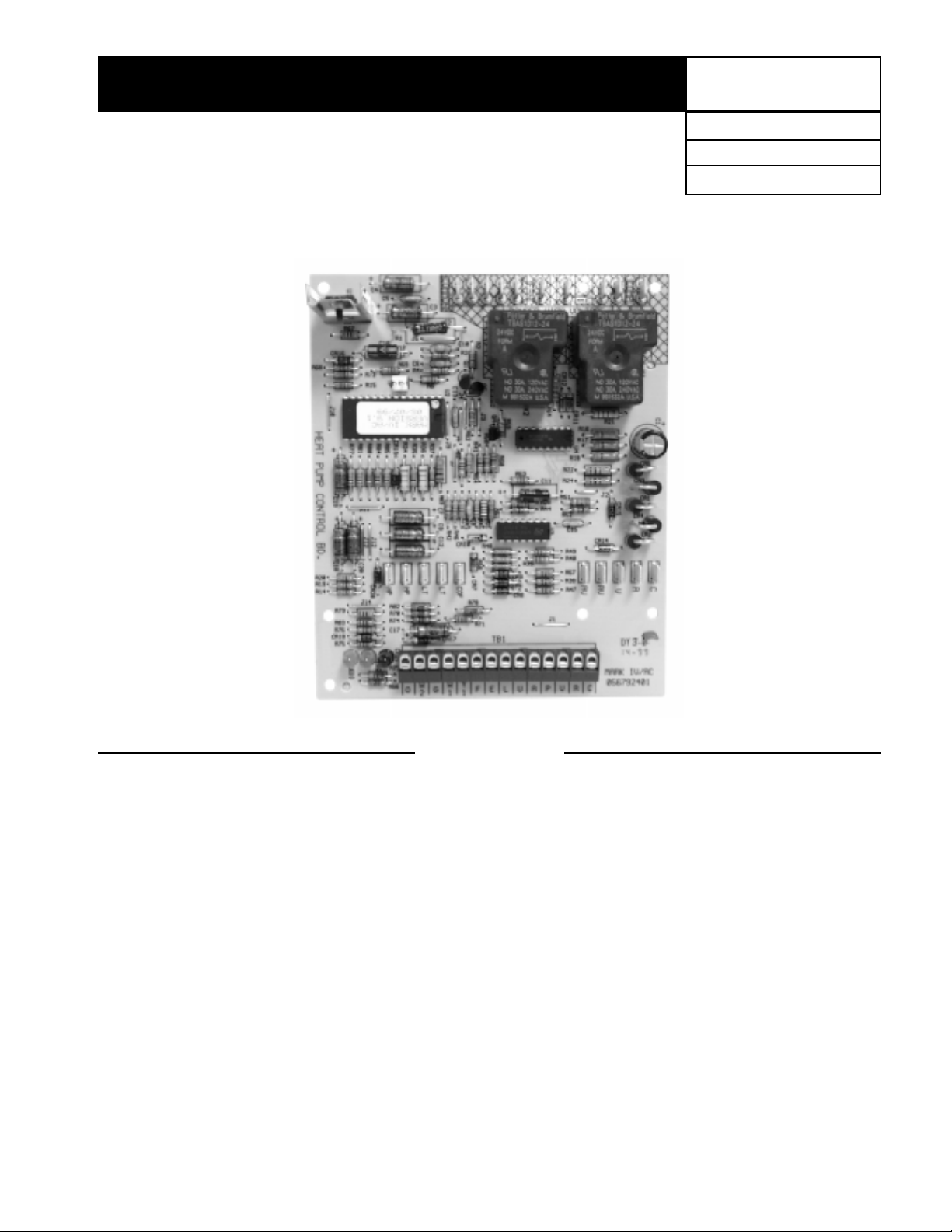
Mark IV/AC Controller For
Water Source Heat Pump Units
Group: WSHP
Part Number: 578993Y
Date: May 1999
Contents
Features of the Mark IV Controller ................................ 2
Initial Power Up................................................................2
General Use and Information ......................................... 2
Occupied Operation ........................................................ 3
Thermostat Inputs (G, Y1, W1, and W2)........................3
Control Inputs (HP, LT, COF, U, L, E, O) 3
Control Outputs (A and P)..............................................3
Fan Operation................................................................. 3
Cooling Mode ................................................................. 3
Heating Mode.................................................................3
Unoccupied Operation....................................................3
Thermostat Inputs (G, Y1, W1, and W2)........................3
Control Inputs (HP, LT, COF, U, L, E, O) 3
Control Outputs (A and P)..............................................3
Fan Operation................................................................. 4
Cooling Mode ................................................................. 4
Heating Mode.................................................................4
Additional Operating Modes .......................................... 4
Load Shed ......................................................................4
Brownout ........................................................................ 4
©1999 AAF-McQuay Incorporated OM 120-2 (Rev. 5/99)
Remote Shutdown.......................................................... 4
High/Low Pressure Faults..............................................4
Low Temperature Faults ................................................5
Condensate Overflow..................................................... 5
Tenant Override.............................................................. 5
Operation of the Fan during most Modes, Faults &
Shutdowns ..................................................................5
Operation with High Speed Jumper ..............................5
Priority of Faults and Modes..........................................5
LED Status and Fault Output Status .............................6
14-PositionTerminal Strip...............................................6
Trouble Shooting the Mark IV/AC Control Board ........ 6
Interfacing the Mark IV/AC Controller
to External Equipment .................................................7
Typical Mark IV/AC Unit Wiring Diagram...................... 8
Page 2
Features of the
Mark IV/AC Controller
The Mark IV/AC controller incorporates features which
improve the operation and safety of AAF-McQuay heat
pumps. These features include:
1. Compressor short cycle protection
2. Brownout protection with time delays for the fan and compressor to prevent damage due to low voltage conditions
3. Condensate overflow protection
4. Refrigerant high / low pressure protection
5. Low temperature protection with automatic condenser
defrost cycle
6. Random start delay compressor to prevent high building
electrical demands when multiple units are simultaneously
switched on during power-up, return from brownouts,
return from load shed, etc.
7. LED’s to indicate operational status and fault indication
8. Controlled delay of the reversing valve to reduce annoying “swish” noise
9. High speed test jumper (TP) used to reduce compressor short cycle and reversing valve delay times to
speed system check out and repair.
10. Load shed control input for energy management systems
11. Remote shutdown control input for remote shutdown
of unit
*
12. Unoccupied control input for night setback control
13. Inputs for both standard (W1) and night setback (W2)
thermostats
Initial Power Up
When power is first applied to the unit, the following events
occur:
1. The board executes a reset routine which sets up the
microcontroller for normal operation. During this routine
the following occurs:
a. The reversing valve may click on and off.
b. The A output goes low for a fraction of a second.
c. The GREEN LED will flash at
approximately 1
d. A new random start delay time between 0 and 32
seconds is generated. A new short-cycle timer is
also generated by adding 180 to the new start delay
time for a total time delay between 180 and 212
seconds. Once these numbers are generated, the
same time delays will be used until the next power
cycle.
2. The microcontroller then checks for the following conditions in the following order:
a. High pressure fault
b. Low temperature fault
c. Load shed signal on
d. Brownout or remote shutdown condition
e. Condensate fault
f. Unoccupied signal on
If any of these conditions are true, the microcontroller
executes the appropriate routine. For example, if the high
pressure switch is open upon power up, the compressor
will not start and the RED LED will flash.
3. If none of the above signals or faults are detected during
start up, the unit will go into normal operation.
1
⁄2 seconds.
1
⁄2 second intervals for
14. Fault output for remote fault indication
15. Operation of the fan during most faults and load shed to
increase comfort
16. Tenant override input to manually switch from unoccupied mode (U) to occupied mode (O)
17. Control board inputs U, L, E, Y1, W1, G, W2, and O have
been designed to operate by connecting to the units
24vac, 24vdc, or chassis ground
The remote shutdown input (E) should not be the sole
*
means of ensuring equipment status when used as a part of
a life-safety control system as the unit fan may operate
during some fault conditions.
CAUTION
The Mark IV/AC circuit board incorporates static sensitive
devices. A static charge from touching the device can
damage the electronic components. To prevent damage
during service, AAF-McQuay Incorporated recommends the
use of static discharge wrist straps which are grounded to the
heat pump chassis through a one mega ohm resistor.
For replacement of a Mark IV/AC circuit board:
1. Connect wrist strap to unit.
2. Remove faulty board and place on static protected surface.
3. Remove replacement board from static protected bag.
Do not touch circuit board; hold by edges.
4. Holding board in grounded hand, install board in unit.
5. Insert faulty board in empty static bag for return.
General Use and Information
The Mark IV/AC control board is provided with three drive
terminals, R (24vac), F (24vdc), and C (0vac) that can be used
by the end user to drive the thermostat inputs (G, Y1, W1, and
W2) and control inputs (U, L, E, and O). Any combination of
or single board drive terminal (R, F, or C) may be used to
operate the Mark IV/AC boards control or thermostat inputs.
However, only one drive terminal (R, F, or C) can be connected to any individual input terminal or damage will occur.
Some of the control inputs are used within the Water Source
Heat Pump and not accessible to the end user. For example
HP, LT, and COF are not available for use by the end user.
Typically the Mark IV/AC board’s R (24vac) terminal is used
to drive the board’s thermostat inputs and control inputs by
connecting it to the R terminal of an industry standard
thermostat. The control outputs of the standard thermostat
are then connected to the Mark IV/AC board thermostat
inputs and control inputs as needed. Any remaining board
input(s) may be operated by additional thermostat outputs or
remote relays (dry contacts only).
All Mark IV/AC board inputs must be operated by dry
contacts powered by the control board’s power terminals.
No solid state devices (Triacs) may be used to operate Mark
IV/AC board inputs. No outside power sources may be used
to operate Mark IV/AC board inputs.
Page 2 / OM 120-2
Page 3
Occupied Operation
Board LED Status
Yellow Green Red
Off On Off
Thermostat Inputs (G, Y1, W1, and W2)
Thermostat inputs used during occupied operation are G, Y1,
and W1, which when energized will activate the Fan Only,
Cooling Mode, and Heating Mode respectively. Input W2,
unoccupied Heating Mode has no effect during occupied
mode.
The Mark IV/AC board is configured so that when either the Y1
or W1 input is energized the unit fan will also be activated with
Cooling or Heating Modes. In other words, energizing Y1 and G
together will have the same effect as energizing just Y1.
The W1 input has priority over the Y1 input. In situations when
both inputs W1 and Y1 become energized (unlikely) in any order
the unit will go into the Heating Mode as described below:
1. For example, if the unit is in Cooling Mode, Y1 energized, and
W1 becomes energized and remains energized, the following will occur:
l The compressor will be de-energized
l The reversing valve will energize 1 minute later (Heating
Mode position)
l The compressor will restart between 180 and 212
seconds (short-cycle timer)
2. If the unit is in Cooling Mode, Y1 energized, and W1 becomes
energized momentarily the controller will de-energize the
compressor for 180 to 212 seconds (short-cycle timer) and
then return to the cooling mode.
3. However, if the unit is in Heating Mode, W1 energized, and
Y1 becomes energized the unit will remain in Heating Mode.
The board will be in occupied
mode if the unoccupied terminal
(U) is de-energized.
3. The P control output is de-energized when the compressor
is energized
When the Y1 terminal is then de-energized, the following
will occur:
1. The compressor is de-energized immediately
2. The fan is de-energized immediately, unless the G terminal
is energized
3. The P control output is energized when the compressor is
de-energized
Compressor time delays may be longer than indicated above as
the short-cycle timer (180 to 212 seconds) will be used as
needed to prevent adverse compressor cycling.
Heating Mode
The W1 terminal controls occupied Heating Mode operation.
When the W1 terminal is energized the following will occur:
1. The reversing valve will be energized immediately
2. The fan will be energized immediately
3. The compressor will be energized after 0 to 32 seconds (start
delay timer)
4. The P control output is de-energized when the compressor
is energized
When the W1 terminal is then de-energized the following will
occur:
1. The compressor will be de-energized immediately
2. The fan will be de-energized immediately, unless the G
terminal is energized
3. The reversing valve de-energizes after 1-minute
4. The P control output is energized when the compressor is
de-energized
Compressor time delays may be longer than indicated above as
the short-cycle timer (180 to 212 seconds) will be used as
needed to prevent adverse compressor cycling.
Control Inputs (HP, LT, COF, U, L, E, O)
The control inputs are High / Low Pressure (HP), Low Temperature (LT), Condensate Overflow (COF), Unoccupied (U), Load
Shed (L), and Remote Shutdown (E). The control inputs will all
be in their normal states during occupied mode. The state of
each control in occupied mode during normal operation is as
follows:
l High / Low Pressure (HP): energized, switch is closed (no
fault)
l Low Temperature (LT): energized, switch is closed (no fault)
l Condensate Overflow (COF): sensing no condensate water
(no fault)
l Unoccupied (U): de-energized (no signal)
l Load Shed (L): de-energized (no signal)
l Remote Shutdown (E): de-energized (no signal)
l Tenant Override (O): has no effect in occupied mode
Control Outputs (A and P)
The control outputs are Alarm Fault (A) and Pump Request (P).
The operation of the control outputs during occupied mode is
as follows:
l Alarm Fault (A): energized (no fault)
l Pump Request (P): energized when the compressor is off,
and de-energized when the compressor is on.
Fan Operation
The G terminal controls Fan Only operation. The fan will start
when the G terminal is energized. De-energizing the G terminal
will cause the fan to stop unless the W1 or Y1 terminals are
energized.
Unoccupied Operation
Board LED Status
Yellow Green Red
On On Off
Thermostat Inputs (G, Y1, W1, and W2)
The only thermostat input used during unoccupied operation is
W2, which when energized will activate Heating Mode. Inputs
G, Y1, and W1 have no effect during unoccupied mode.
Control Inputs (HP, LT, COF, U, L, E, O)
The control inputs are High / Low Pressure (HP), Low Temperature (LT), Condensate Overflow (COF), Unoccupied (U), Load
Shed (L), and Remote Shutdown (E). The state of each control
input during unoccupied mode during normal operation is as
follows:
l High / Low Pressure (HP): energized, switch is closed (no fault)
l Low Temperature (LT): energized, switch is closed (no fault)
l Condensate Overflow (COF): sensing no condensate water
(no fault)
l Unoccupied (U): energized (signal provided)
l Load Shed (L): de-energized (no signal)
l Remote Shutdown (E): de-energized (no signal)
l Tenant Override (O): see section “Tenant Override Mode”
The board will be in unoccupied
mode if the unoccupied terminal
(U) is energized.
Cooling Mode
The Y1 terminal controls Cooling Mode operation. When the Y1
terminal is energized, the following will occur:
1. The fan will be energized immediately
2. The compressor will be energized after 0 to 32 seconds (start
delay timer)
Control Outputs (A and P)
The control outputs provided by the Mark IV/AC board are
Alarm Fault (A) and Pump Request (P). The operation of the
control outputs during unoccupied mode is the same as in
occupied mode. See occupied operation.
OM 120-2 / Page 3
Page 4

Fan Operation
The G terminal has no effect during unoccupied mode. Operation of the fan is controlled by the W2 input.
Cooling Mode
Cooling operation is not provided during unoccupied mode.
Heating Mode
The W2 terminal controls unoccupied Heating Mode operation.
When the W2 terminal is energized the following occurs:
1. The reversing valve is energized immediately
2. The fan is energized immediately
3. The compressor will start after 0 to 32 seconds (start
delay timer)
4. The P control output is de-energized when the compressor
is energized
When the W2 terminal is then de-energized the following
occurs:
1. The compressor is de-energized immediately
2. The reversing valve de-energizes after 1-minute
3. The P control output is energized when the compressor is
de-energized
Compressor time delays may be longer than indicated above as
the short-cycle timer (180 to 212 seconds) will be used as
needed to prevent adverse compressor cycling.
Additional Operating Modes
Load Shed
Board LED Status
Yellow Green Red
Off Off On
or fault. Load shed is provided so that when properly connected
to a building automation system, remote switch, etc., the L
terminal can be used to deactivate the compressor. The load
shed input may also be used as part of a boiler-less system kit,
which will disable the compressor by energizing the L terminal
when loop water temperature drops. The fan will operate
normally during load shed mode.
Some faults and modes have higher priority than load shed
mode. See the section “Priority of Faults and Modes”.
When the L terminal is energized the following occurs:
1. The compressor is immediately de-energized
2. The reversing valve will be de-energized after 1-minute
When the L terminal is then de-energized, the controller will
automatically return to normal operation.
Brownout
Board LED Status
Yellow Green Red
Off Flash Off
source heat pump drops, the 24vac supply to the control board
will also drop. When the line voltage supplied to the unit drops
below approximately 80% of the unit nameplate rated value the
controller will go into brownout mode. The controller will then
remain in brownout mode until line voltage returns to approximately 90% of the unit nameplate value. Brownout mode is
provided to protect the water source heat pump’s motors from
low voltage conditions.
When in brownout mode all thermostat and control inputs have
no effect on unit operation. No faults or modes have higher
The Mark IV/AC board will be in
load shed mode when the L
terminal is energized unless over
ridden by a higher priority mode
The Mark IV/AC board is
designed to monitor the 24vac
supply to the board. If the line
voltage supplied to the water
priority than brownout mode. Remote shutdown and brownout
modes have the same level of priority. See the section “Priority
of Faults and Modes”.
When the unit is in brownout mode the following occurs:
1. The compressor is immediately de-energized
2. The reversing valve is immediately de-energized
3. The fan is immediately de-energized
4. Fault terminal (A) is de-energized (fault)
When the line voltage supplied to the unit returns to acceptable
levels (~90% of nameplate) the controller will return to the
current mode.
Remote Shutdown
Board LED Status
Yellow Green Red
Flash Off Off
when properly connected to a building automation system,
remote switch, etc., the E terminal can be used to shut down the
water source heat pump.
When in remote shutdown (E terminal energized) no other
thermostat or control inputs will have effect on unit operation.
No faults or modes have higher priority than remote shutdown.
Remote shutdown and brownout modes have the same level of
priority. See the section “Priority of Faults and Modes”.
When the unit is in remote shutdown mode the following
occurs:
1. The compressor is immediately de-energized
2. The reversing valve is immediately de-energized
3. The fan is immediately de-energized
4. Fault terminal (A) is de-energized (fault)
When the E terminal is de-energized the unit will automatically
return to normal operation.
The remote shutdown input (E) should not be the sole
*
means of ensuring equipment status when used as a part of
a life-safety control system as the unit fan may operate
during some fault conditions.
The Mark IV/AC board will be in
remote shutdown when the E
terminal is energized. Remote
shutdown is provided so that
High / Low Pressure Faults
Board LED Status
Yellow Green Red
Off Off Flash
tect from excessively high or low refrigerant pressures. The
Mark IV/AC board will monitor these switches connected in
series through the HP control input terminals on the board.
When the HP circuit is open the controller will go into the
pressure fault mode. The fan will operate normally during the
pressure fault mode.
Only brownout and remote shutdown modes have higher
priority than the pressure fault mode. See the section “Priority
of Faults and Modes”.
When the unit is in pressure fault mode the following occurs:
1. The compressor is immediately de-energized
2. The reversing valve is immediately de-energized
3. The fault terminal (A) is de-energized (fault)
After the HP circuit is then closed the unit will not return to
normal operation until the control board is reset. The unit is
locked out in this manner after a high / low pressure fault to help
insure that a service technician inspects it to verify no problems
exist. The control board is reset by a short interruption of unit
power.
Normally closed high and low
refrigerant pressure switches are
used as needed within the water
source heat pump to help pro-
Page 4 / OM 120-2
Page 5

Low Temperature Faults
Board LED Status
Yellow Green Red
Flash Off Off
cessively low water out temperatures. The Mark IV/AC board
will monitor this switch connected to the LT control input
terminals on the board. When the LT circuit is open the controller
will go into the low temperature fault mode. The controller is
programmed for different responses if a low temperature fault
is detected during heating or cooling modes. The control board
LED status shown below only occurs when a low temperature
fault is detected during heating mode. No LED status changes
occur if the fault is detected while in cooling mode. The fan will
operate normally during the low temperature fault mode.
Brownout, remote shutdown, and pressure fault modes have
higher priority than the low temperature fault mode. See the
section “Priority of Faults and Modes”.
When the unit senses a low temperature fault while in heating
mode the following occurs:
1. The reversing valve will be immediately de-energized
2. The compressor will run in cooling mode for 1-minute
(heating the unit’s water coil) and then be de-energized
3. The fault terminal (A) is de-energized (fault)
When the LT circuit is then closed after a fault during heating
mode the unit will not return to normal operation until the control
board is reset. The unit is locked out in this manner after a low
temperature fault to help insure that a service technician inspects it to verify no problems exist. The unit is reset by a short
interruption of unit power.
When the unit senses a low temperature fault while in the cooling
mode the following occurs:
1. The compressor is immediately de-energized
2. The fault terminal (A) remains energized (no fault)
When the LT circuit is then closed after a fault during cooling
mode the unit will automatically return to normal operation.
A normally closed low temperature switch is used as needed
within the water source heat
pump to help protect from ex-
Condensate Overflow
Board LED Status
Yellow Green Red
On Dim Off
high condensate water levels are detected during cooling mode
the controller will go into condensate fault mode. No condensate overflow fault will occur during heating modes, therefore
the unit will be allowed to heat with high condensate water
levels. The fan will operate normally during the condensate
overflow fault mode.
Some faults and modes have higher priority than condensate
overflow mode. See the section “Priority of Faults and Modes”.
When the unit senses a condensate overflow fault while in
cooling mode the following occurs:
1. The compressor is immediately de-energized
2. The fault terminal (A) is de-energized (fault)
When condensate levels return to normal, the controller will
automatically return to normal operation.
The Mark IV/AC board is designed to sense when condensate water levels in the drain pan
become excessively high. When
Tenant Override
Prior to reviewing this section, read “Occupied Operation” and
“Unoccupied Operation” sections. The Mark IV/AC board will
be in tenant override mode when the O terminal is momentarily
energized during a period when the water source heat pump is
in unoccupied mode (U terminal energized). Tenant override is
provided so that when the controller is placed into unoccupied
mode by a building automation system, timer, remote switch,
etc., a tenant returning to the controlled space during the
unoccupied period can activate the tenant override input (O)
forcing the unit into occupied mode. A tenant override option is
provided for this purpose on some AAF-McQuay thermostats.
Any remote button or switch with momentary dry contacts can
be used for this purpose. During the 2-hour tenant override
period the W2 input will be ignored and the G, Y1, and W1 inputs
will be used (see Occupied Operation) for unit operation. If after
the 2-hour time limit the U terminal is still energized the unit will
return to unoccupied mode. If after the 2-hours the U terminal
is de-energized the unit will remain in occupied mode.
Operation of the Fan during most Modes,
Faults, and Shutdowns
To increase the level of comfort the Mark IV/AC controller is
configured to allow fan operation during most modes, faults,
and shutdowns. However, the fan will not operate during
brownout mode. During most modes, faults, or shutdowns the
fan will operate under the following conditions:
1. In occupied modes, whenever the thermostat inputs G, Y1,
or W1 are energized
2. In unoccupied modes, whenever the thermostat input W2 is
energized
Operation with the High Speed Jumper
The Mark IV/AC board is provided with a high-speed jumper
terminal labeled TP to speed system check out and troubleshooting. This jumper is intended for AAF-McQuay factory unit
testing and should only be used by trained service technicians
as several timing functions are reduced to speed system check
out. When a jumper is placed on the TP terminal, operation of the
unit is normal except the following timing values are used:
1. Reversing valve delay time = 2 seconds
2. Compressor delay time = 6 seconds
Note: It is required that power be disconnected to the unit when
installing or removing the high-speed jumper.
Note: It is required that the high speed jumper only be used for
short periods of time and only to aid the testing of the
unit’s operation by a trained service technician. The
jumper must be removed for normal unit operation. If the
jumper is left on after system check out, the unit will be
damaged.
Priority of Faults and Modes
The Mark IV/AC control board is configured with mode and fault
priorities. The higher level priorities, lower numbers in the table
below, override lower level modes and faults under most
conditions. There are some exceptions to this priority list. For
example, tenant override has no affect on occupied modes.
Priority
Level
in heating mode only
*
Mode or Fault
1 Emergency Shutdown Mode + Brownout Fault
2 High / Low Pressure Fault
3 Low Temperature Fault
4 Load Shed Mode
5 Tenant Override Mode
6 Unoccupied Heating Mode
7 Occupied Heating Mode
8 Condensate Overflow Fault
9 Occupied Cooling Mode
*
OM 120-2 / Page 5
Page 6

LED Status and
Fault Output Status
Board Status LED’s Fault Output
Mode Yellow Green Red Terminal A
Occupied Off On Off Energized
Unoccupied On On Off Energized
Load Shed Off Off On Energized
Condensate Overflow On Dim Off De-energized
High / Low Pressure Fault Off Off Flash De-energized
Low Temperature Fault*Flash Off Off De-energized
Brownout Off Flash Off De-energized
Emergency Shutdown Off Flash Off De-energized
in heating mode only
*
Note: The fault output is energized when no faults exist. The
fault output is de-energized during faults and when unit
power is off.
14-Position T erminal Strip
Pin Designation Description
1 C Transformer ground (0vac)
2 R Transformer supply (24vac)
3 V -DC power connection
4 P Pump request output
5 A Alarm fault output
6 U Unoccupied input
7 L Load shed input
8 E Remote shutdown input
9 F +DC power connection
10 Y1 Occupied cooling mode input
11 W1 Occupied heating mode input
12 G Fan only input
13 W2 Unoccupied heating mode input
14 O Tenant override input
Trouble Shooting the
Mark IV/AC Control Board
Note: Only trained and experienced service technicians may
perform the trouble-shooting techniques described below.
l How can I prove the water source heat pump is operating
properly?
Test the water source heat pump’s fan, cooling, and heating
operation. To do this first switch off unit power, remove and
safely secure all wires connected to the board’s 14-position
terminal strip, and then switch on unit power. Make sure no
faults exist. If no faults exist the green LED should be on solid
with the red and yellow LED’s off. If another LED pattern
appears try resetting the controller by temporarily
interrupting unit power. All faults must be eliminated prior to
performing this test. If the board is functioning properly the
only possible fault conditions with all wires removed from the
board’s 14-position terminal strip are high / low pressure, low
temperature, condensate overflow, or brownout. Remember
that while performing this test the compressor may take
more than 3-minutes to start due to the short cycle timer.
Return all wiring to original positions when testing is complete.
To test fan operation: connect a jumper from the R terminal to
the G terminal. The fan will start if the board and unit are
operating properly; disconnect the jumper when complete.
To test cooling operation: connect a jumper from the R
terminal to the Y1 terminal. The unit will go into cooling mode if
the board and unit are operating properly; disconnect the
jumper when complete.
To test heating operation: connect a jumper from the R
terminal to the W1 terminal. The unit will go into heating mode
if the board and unit are operating properly; disconnect the
jumper when complete.
l How can I prove the Mark IV/AC board is receiving 24vac and
that its DC power supply is operating correctly?
The Mark IV/AC board is provided 24vac by the water source
heat pump’s 24vac transformer. The board has a built-in DC
power supply that converts a portion of the 24vac into 24vdc.
A voltage meter set to read AC voltage can be used to verify
the 24vac supply to the board by placing the meter’s leads
onto board terminals C and R. You should read approximately 24vac if it is operating correctly. A voltage meter set
to read DC voltage can be used to verify the board’s DC
voltage supply by connecting the meter’s leads to board
terminals F (+) and V (-). You should read approximately
between +28 to +33vdc if the board is operating correctly.
l What voltages will I measure at the thermostat and control
inputs on the Mark IV/AC board when they are energized or deenergized?
The Mark IV/AC board is designed to be very flexible as to
how its thermostat (G, Y1, W1, and W2) and control inputs (U,
L, E, and O) are activated. The board inputs are capable of
being energized by 24vac, 24vdc, or a connection to ground.
Terminals R (24vac), F (24vdc), and C (ground) on the Mark
IV/AC board are the drive terminals that must be used to
energize the board’s thermostat and control inputs. A table
of voltages are provided below that will be measured for
each of the board’s drive terminals. Before measuring any
voltage, switch off unit power, remove and safely secure all
wires connected to the board’s 14-position terminal strip,
and then switch on unit power. Use a voltage meter to verify
the de-energized input voltages and compare with the table.
Then, using jumpers, energize the desired inputs (U, L, E, G,
Y1, W1, W2, and O) one at a time with the drive terminal of
choice. Use the voltage meter to verify the jumper-connected terminal voltage and compare with table results. This
is also a good method to test board function. The voltages
given in this table are approximations that will vary slightly
based upon unit options, present power consumption, etc.
Be sure that when testing is complete you remove any
jumpers and reconnect all wires to their proper location with
unit power off. The table below may also be used to determine if an input is energized or de-energized with wiring
connected to the 14-position thermal strip.
Using Using Using
Drive Terminal R Drive Terminal F Drive Terminal C
(24vac) (ground) (24vdc)
De-energized Energized De-energized Energized De-energized Energized
Place the
Meters
Red (+) Lead
on Input to
be checked
U, L, E, Y1, W1, 10 to 22 to
G, W2, O 14vac 26vac 33vdc 14vac 26vac
Place the Place the Place the
Meters on Meters Meters
Black (-) Lead Black (-) Lead Black (-) Lead
on C on V on R
0vdc
30 to 10 to 22 to
l Do I need to use the same drive terminal for all Mark IV/AC
board inputs?
No. You can use one, two, or all three of the drive terminals.
For example, you can use terminal R to drive inputs G, Y1,
W1, and W2; terminal C to drive inputs U, L, E; and then
terminal F to drive input O. The R terminal (24vac) is the
terminal most commonly used to drive the control board’s
thermostat and control inputs. You cannot connect two drive
terminals to one board input or board damage will result.
Page 6 / OM 120-2
Page 7

l Can I use 24vac or 24vdc power from the water source heat
pump to provide power to my programmable thermostat or
some other external devices that I need to power?
No. The water source heat pump is provided with a 24vac
transformer that is capable of providing power only to
devices supplied with the unit from the factory or to
approved add on options typically shipped with the unit or
purchased as accessories. The Mark IV/AC board cannot be
used to provide 24vdc power to external equipment.
If you need to power external devices you will need to
provide power from another location.
l How can I test the unit’s high / low pressure switch or the low
temperature switch?
The Mark IV/AC board uses its DC power supply as a source
for these normally closed safety switches. There are two HP
and two LT spade terminals located on the Mark IV/AC board
for this purpose. You can use a voltage meter to determine
if the switch is open or closed. Carefully placing the meter’s
probes, one on each of the control board’s HP terminals, you
will measure approximately 30vdc when the switch is open
(fault) or 0vdc when the switch is closed (no fault). The same
procedure can be applied to the LT terminals. To prove the
circuit operates you can pull one HP or LT spade connection
off the control board to cause the fault condition. Be sure to
replace these connections if removed.
l How can I test the condensate overflow circuit?
The condensate overflow circuit is designed to sense a
connection to chassis ground through the drain pan when
the drain pan is over full with condensate water. To test this
circuit, activate the fault when the unit is in cooling mode by
connecting a jumper between the COF spade terminal and
the C (ground) spade terminal. Be sure to remove this jumper
when testing is complete.
l Can I use a 24vac solenoid on the reversing valve?
No. The Mark IV/AC board is designed to drive a 24vdc
reversing valve solenoid. If you switch the 24vdc solenoid
provided with the water source heat pump with a 24vac
solenoid you will damage the Mark IV/AC control board. This
type of damage to the board may not occur immediately and
it can cause the fan and or compressor outputs to operate
erratically or not operate at all. If the compressor and or the
fan do not operate as expected, check the reversing valve
solenoid to ensure it is the proper voltage type.
Interfacing the Mark IV/AC
Controller to External Equipment
A 14-position terminal strip is provided on the control board to
interface to external equipment.
l The Mark IV/AC board’s thermostat input terminals may be
directly interfaced with any standard or night setback thermostat that uses mechanical dry contacts. Power cannot be
supplied from the water source heat pump for electronic
thermostats that require a separate power supply for their
internal operation except hose provided by AAF-McQuay.
Only the programmable and mercury bulb type thermostats
offered by AAF-McQuay are proven to operate properly with
the Mark IV/AC control board. AAF-McQuay makes no
guarantees about any other thermostat or control device
interfaced by the end user with the Mark IV/AC board.
l Care must be used to isolate all external power sources from
the Mark IV/AC board to prevent ground loops and other
unpredictable electrical problems. Only dry mechanical
contacts should be used to operate or interface with the
Mark IV/AC board’s thermostat and or control inputs.
If external equipment with its own power supply is used to
interface with or control the Mark IV/AC board’s thermostat
and or control inputs, you must use mechanical relays to
isolate the two power systems. For example, if you have a
building automation system, controller, etc., and you wish to
use a digital output from the building automation system or
controller that is internally powered, then you must use an
additional mechanical relay (not supplied by AAF-McQuay)
to isolate the Mark IV/AC board.
l If you need to connect multiple water source heat pumps
with Mark IV/AC control boards, use a connection to ground
(terminal C) to drive the thermostat (G, Y1, W1, and W2) and
control inputs (U, L, E, and O). For example, the load shed
input of multiple Mark IV/AC controllers may be daisychained together through one set of dry contacts to ground
(C). This is useful if you need to operate multiple units from
one thermostat or if you need to signal multiple units from one
location. However, care must be used to ensure that this type
of connection has very low resistance to ground for proper
operation. To keep resistance low, wire runs should be kept
short and wire gauges may need to be increased. AAFMcQuay also offers special control boards and relays for
operating two or three water source heat pumps from one
thermostat which should be used when multiple unit operation is required.
l Due to the nature of triacs and other solid state devices they
cannot be directly used to operate the Mark IV/AC board’s
thermostat or control inputs. To interface triacs or other solid
state switching devices to the Mark IV/AC board inputs, you
need to separate them from the board using mechanical
relays. To do this, use the triac or solid state device to drive
a mechanical relay (not supplied by AAF-McQuay), then use
the mechanical relay’s dry contacts to drive the desired
Mark IV/AC board input.
l Do not connect the coils of standard mechanical relays in
series or parallel with the Mark IV/AC board inputs as you
may introduce electrical noise causing unexpected water
source heat pump operation or board damage. AAF-McQuay
offers a special relay for this purpose when additional signaling is needed.
l The Mark IV/AC board’s fault terminal (A) is primarily de-
signed to operate a fault LED on the AAF-McQuay wall
thermostats. Terminal A is designed to maintain an equivalent DC voltage level with board terminal F (+30vdc) when no
faults exist. When a fault exists, the A terminal will be lowered
to 0vdc. To use this output to signal external equipment,
connect the coil of a 24vdc mechanical relay (not provided by
AAF-McQuay) between terminals F and A on the Mark IV/AC
board. Then use the dry contacts of this mechanical relay as
an alarm or fault signal to external equipment or systems.
When using this output to signal external equipment it cannot
be used to operate a thermostat fault LED and vice versa.
l The Mark IV/AC board’s pump request terminal (P) is de-
signed for use as a signal to external equipment that water
flow is required by the heat pump. The P terminal follows
compressor operation inversely and will equal approximately 30vdc when the compressor is off and 0vdc when the
compressor is on. The P terminal should only be used as a
signal to pump controls if the water loop can respond with
water flow fast enough (3-5 seconds) to prevent unit shutdown due to high refrigerant pressure from a lack of water
flow. If adequate water flow is a concern, and the load shed
terminal (L) is not used for other purposes, you may use the
L terminal to prevent compressor operation until water flow
is established by using a flow control device as a signal to
allow compressor operation when flow exists.
OM 120-2 / Page 7
Page 8

Typical Mark IV/AC Unit Wiring Diagram
L1
COMMON
L2 L3 GND
FC- FAN CONTACTOR
CC- COMPRESSOR CONTACTOR
HTR- CRANKCASE HEATER(CCW ONLY)
CAP- MOTOR CAPACITOR
43
LO TEMP
CONDENSATE
SENSOR
42
HI PRESS
2
CC
FC
16
BK
FC
15
13
30
COMPR
MOTOR
HTR
FAN
MOTOR
24 VAC
YE
BL
14
CC
32
3
RDRD
11
CAP
480 BK/RD
575V VI
XFORMER
44
34
1
1210
CC
37
41
45
LO PRESS
40
BK
BK
REVERSING
S
AAF-McQuay Incorporated
4900 Technology Park Boulevard, Auburn, NY 13201-9030 USA, (315) 253-2771
Printed on recycled paper containing at least 10% post-consumer material.
VALVE
SOLENOID
(HT PUMP ONLY)
HP
W
O G F E L U A P V R C
2
HP
LT
LT
W1Y
COMMON
COF
1
48
FAN
LI
RV
RV
MARK IV
BOARD
47
V
PC
COMP
R
C
©1999 AAF-McQuay Incorporated
OM 120-2 (Rev. 5/99)
 Loading...