

McQuay MAC 070 C, MAC 035 C, MAC 050 C, MAC 065 C, MAC 040 C Installation And Maintenance Manual
...Page 1
CMAC - C - 2004
Air-Cooled Mini Chiller
Models: MAC 030 C/CR
MAC 035 C/CR
MAC 040 C/CR
MAC 050 C/CR
MAC 065 C/CR
MAC 070 C/CR
MAC 080 C/CR
MAC 100 C/CR
MAC 120 C/CR
MAC 150 C/CR
Page 2

Contents
Introduction ...................................................................................................................2
Nomenclature ................................................................................................................ 2
Features .................................................................................................................... 3 - 4
General Specification.................................................................................................... 5
Controller ...................................................................................................................... 6
Specifications ........................................................................................................ 7 - 15
Performance Characteristics ............................................................................. 16 - 19
Technical Data ............................................................................................................ 20
Outlines and Dimensions .................................................................................... 21 - 23
Wiring Diagrams .................................................................................................. 24 - 33
Installation ............................................................................................................ 34 - 42
Servicing and Maintenance ........................................................................................ 43
Troubleshooting .......................................................................................................... 44
Troubleshooting with Microprocessor ...................................................................... 45
Schematic Diagram .............................................................................................. 46 - 49
Part List and Exploded View................................................................................ 50 - 51
Note: Installation and maintenance are to be performed only by qualified personnel who are
familiar with local codes and regulations, and experienced with this type of equipment,
Caution: Sharp edges and coil surfaces are a potential injury hazard. Avoid contact with them.
Warning: Moving machinery and electrical power hazards. May cause severe personal injury or death.
Disconnect and lock off power before servicing equipment.
"McQuay" is a registered trademark of McQuay International. All rights reserved throughout the world.
2003 McQuay International
"Bulletin illustrations cover the general appearance of McQuay International products at the time of publication
and we reserve the right to make changes in design and construction at any time without notice."
Page 1
Page 3

Introduction
For years, McQuay international has earned a reputation for providing the industry with various highest
qualities and most technologically advanced air conditioning systems. Now Shenzhen McQuay is proud to
introduce the new generation mini air-cooled chiller-MAC C series. Inherited from the advantage of the
earlier product experiences and introduced the most up-to-date technology, the new MAC C series are
designed with the always-in-mind concept - to satisfy customers’ requirements of high efficiency, comfort,
safety, intelligence to maximum extent. The unit can be flexibly coupled with multi fan coil units, easily
operated with artificial intelligence. Additionally combined with indoors top level decoration, this brings you to
enjoy the nobility coming from central air conditioning.
Providing the features such as high efficiency, low noise, compactness, simple operation, safety running,
easy installation and maintenance etc., the unit is widely equipped in plant, station, hotel, villa, office
building, top-level apartment as well as process cooling application.
Nomenclature
M AC 030 C R
Brand Name Nominal __ Cooling Only
(McQuay) Cooling Capacity R - Heat Pump
Water Source Generation
Heat Pump
Page 2
Page 4

Features
Superior Performance
• Extensive research work coupled with world leading manufacturing technology has caused the new
design with superb performance and high efficiency.
• Stringent quality control and component selection ensure performance and reliability. Major components
are rigorously tested and qualified prior to usage in the machine.
• Every machine design has passed many hours of rigorous testing to ensure the machine reliability,
durability and quality.
• Scroll compressor brings much higher energy efficiency. High efficiency heat exchanger ensures
strenuous exertion of equipment capacity. Dedicated water pump particularly designed for air
conditioning engineering is operating steadily with minimum vibration and noise.
For MAC080C/CR to MAC150C/CR
• These units are designed with double independent refrigerating system, greater energy saving is
achieved by only one compressor on duty under part load condition.
Simple To Operate
• The MAChine is complete with intelligent microprocessor controller and temperature sensor to
automatically control the operation to its optimum condition, making it very simple to operate. All
temperature settings are finished before shipment. The only thing for user to do is to start the unit by
pressing the ON/OFF button after ensuring unit proper function, then every operation can be
automatically performed by the unit itself.
• Either wireless remote controller or wired remote controller is ready for choosing to meet satisfactory
indoor unit control, both compatible with the unit.
Friendly Installation
• The machine has been designed with friendly installation in mind such that no refrigeration charging or
copper pipe brazing is required on site.
• Threaded fitting is provided for easy water piping connection on site.
• Water inlet and outlet are provided on both sides of the machine such that piping can be connected on
either side of the machine.
• Rust resistant PP-R composite water pipe with good insulation property and high durability is standard
parts in the machine.
• Stainless steel taper threaded fittings target convenient disassembly or assembly.
• For MAC080C/CR to MAC150C/CR, expansion chamber, water pump and water flow switches are
already equipped in this compact packaged unit with top air discharge. In addition, McQuay provides
accessory hydraulic kit with water storage tank, auto water fill valve, auto air vent valve, auto pressure
relief valve and strainer integrated in, aiming at ensuring high efficiency and safe operation. For
MAC030C/CR to MAC070C/CR, expansion chamber is equipped in the accessory hydraulic kit instead
of being incorporated in unit.
For MAC030C/CR to MAC070C/CR
• Both front and rear sides can be served as access to performing wiring and maintenance.
Safety Control
• Protection devices such as dual pressure protection and overload protection etc. is provided to ensure
unit operating within safety condition range. The microprocessor-based controller automatically directs
system on or off by processing the water temperature feedback. If the water temperature falls to
unacceptable low point, the controller automatically shut off the system to prevent hydraulic system
internal freeze for unit safety operation. Meanwhile, the microprocessor-based controller automatically
monitors every component operating status and malfunction, and feedback it to indoor controller to
greatly ease the work of status monitor and troubleshooting.
All Weather
• The cabinet is made of electro galvanized mild steel sheet, coated with baked polyester power to ensure
the units extra durability in all climates against sun, rain, wind corrosion.
• Space saving (small footprint) design of the machine eliminates large installation area requirement, no
need for equipment room.
• The machine uses high quality parts to ensure durability in various climate conditions.
Page 3
Page 5

Simple To Maintain
• The simple design of the machine allows for maximum serviceability. All components are with reach of
the maintenance personnel upon open up of the servicing panel. If emergency shutoff occurs, the
microprocessor-based controller will indicates the fault cause to quicken and ease troubleshooting.
Three Color Appearance Available (For MAC030C/CR to MAC070C/CR)
• There are three optional colors-blue, green and red available to be easily choose to meet customers’
requirements, so the unit can be harmonically blend into building overall look.
Page 4
Page 6

General Specification
Compressor
McQuay Mini Chillers are equipped with highly efficient, reliable and silence scroll compressor, double for
MAC080C(R) to MAC150C(R), one for MAC030C/CR to MAC070C/CR.
Air-Cooler Condenser
The air-cooled condenser coil consists of staggered rows of 3/8’’ O.D. seamless copper tube, mechanically
expanded into die formed aluminum fins to ensure optimum heat exchange capability.
Condenser Fan Motor
To achieve the high air change requirement, the unit is equip with the high air flow propeller fan. The fan is
direct driven by weatherproof motor to ensure reliable continuos operation.
Evaporator
The heat exchanger is made of stainless steel plates closely arranged and brazed together to ensure high
heat exchange efficiency. The complete heat exchanger is insulated with thermal insulation closed cell
rubber foam to give optimum thermal insulation.
Refrigerant Circuit
The refrigerant circuit is factory brazed and evacuated before accurately charged with R22 to ensure
optimum operating requirement. To ensure flawless continuous operation, each refrigerant circuit is
equipped with a carefully sized capillary tube.
Additional Safety Protection
The units are equipped with intelligently designed safety control to ensure continuous safe operation. High
and low pressure switch is provided to prevent the compressor damage resulting from both abnormally high
discharge head pressure or low pressure due to insufficient gas. The compressors are provided with crank
case heater to prevent liquid migration during the off cycle and also to ease the start up of the unit.
The standard electronic controller provides accurate water temperature control in the circuit by closely
monitoring and reacting to the input from the water entering temperature, water leaving temperature and
ambient air temperature.
Flow switch is provided in the unit to protect against damage to the water pump.
During abnormal condition, the electronic controller will turn the unit off and the then display the faulty of
operation. (See Troubleshooting sheet)
Page 5
Page 7
Controller
The controller accomplishes its control function with its built-in microprocessor. The two parameters,
temperature and water flow rate, have been factory set before shipment, no need for users to reset them.
The controller will display unit operation status to favor specialized personnel to monitor unit operating
condition for maintenance if necessary. When the system is cut off due to malfunction, the controller will
display the corresponding failure code for easy trouble shooting.
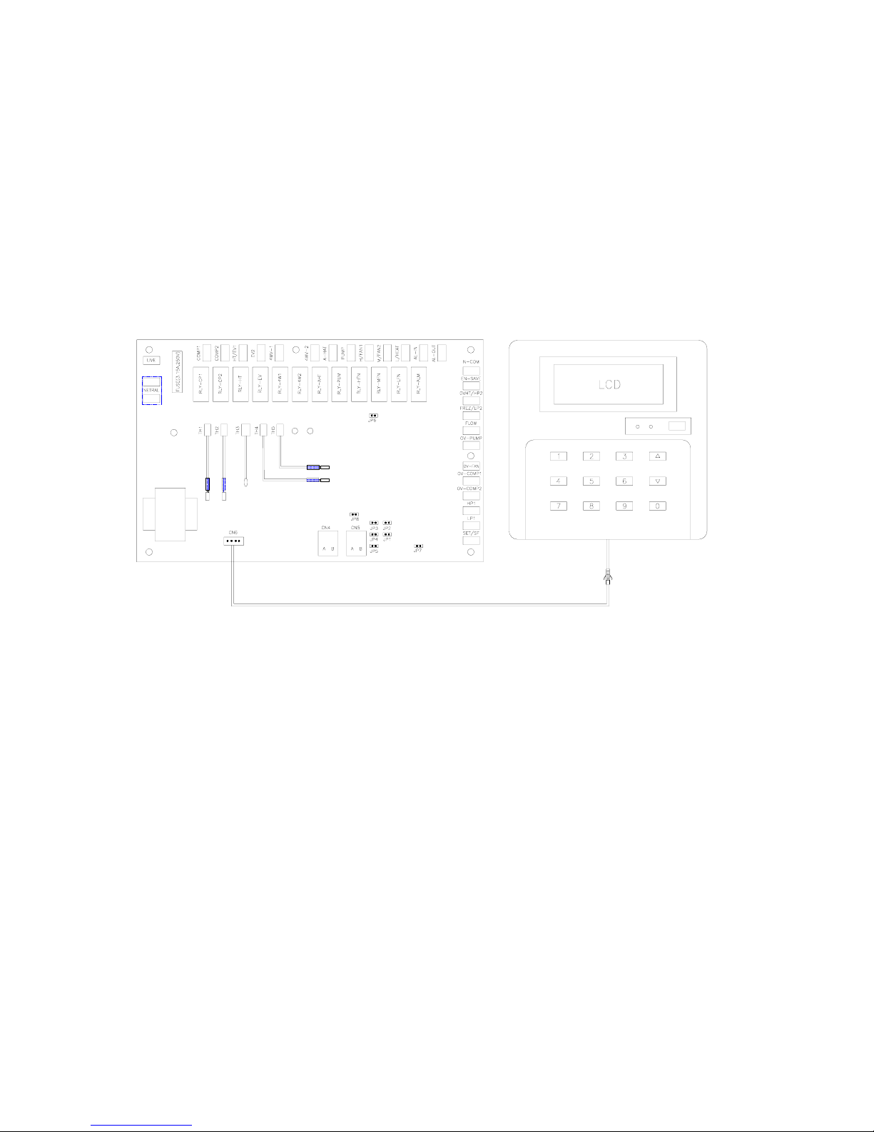
Installation and connection
After removing the terminal box cover, you will find the indoor controller, 20m long indoor connection wire,
and 1.5m long maintenance connection wire. Decide a suitable place for installing the indoor controller, you
can either mount it on wall or embed it in wall. Open the back cover of the indoor controller, plug one end of
the indoor connection wire to the CN3 connector located on controller, insert another end to the CN6
connector located on PCB, then assembly the terminal box cover back, now this work is finished.
Please ensure the 1.5m maintenance connection wire being in good keep for later maintenance by
specialized personnel.
Indoor LCD controller
PCB MAI N
BOARD
TRANSFORMER
R
E
T
U
R
N
W
A
T
E
R
T
E
M
P
.
S
E
N
S
O
R
HOUR
TIMER
MCH03A
PARAMETER
SET
GROUP
OPERATION
WEEK SET
EXIT WEEK
CLEAR
UNIT
No.
MODE
SC302A
CONTROLLER
OK
MINUTE
ROOM
TEMP.
ON/OFF
LED1
LED2
S
U
P
P
L
Y
W
A
T
E
R
T
E
M
P
.
S
E
N
S
O
R
R
E
T
U
R
N
A
I
R
T
E
M
P
.
S
E
N
S
O
R
D
E
F
R
O
S
T
I
N
G
T
E
M
P
.
S
E
N
S
O
R
1
D
E
F
R
O
S
T
I
N
G
T
E
M
P
.
S
E
N
S
O
R
2
After switching on power, the indoor controller will display system time, indoor temperature and unit status.
During normal operation, it will display the unit return water temperature.
When failure occurs, it will emit alarm, both audible and visual. Meanwhile show a corresponding error code.
Please see Troubleshooting With Microprocessor sheet.
a) On/off
Start an operation
First press [MODE] button, select “cooling” or “heating” mode, then press [ON/OFF] button, the yellow lamp
besides the [ON/OFF] button lights up and the system starts.
Stop an operation. Press the [ON/OFF] button again, the yellow lamp goes off and the system stops.
b) Indicating lamps on PCB
When the power supply is switched on, the red lamp lights up.
When the system is on operation, the green lamp lights up.
c) Below are the controllers’ protection functions and features, not its faults.
When restarting the unit after last start or stop, the unit automatically starts compressor and fan after the
lapse of approximately three minutes.
During defrosting cycle, the outdoor fan is stopped.
Page 6
Page 8

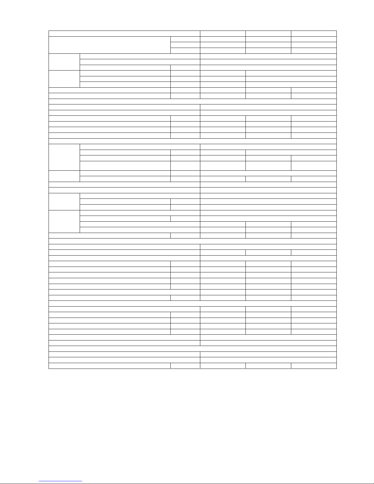
Specifications
Cooling Only Unit (50Hz)
MODEL MAC030C MAC035C MAC040C
Btu/hr 25,600 30,700 39,200
kcal/hr 6,450 7,740 9,890
NOMINAL COOLING CAPACITY
Watt 7,500 9,000 11,500
MATERIAL Electro-galvanised Mild Steel
FINISH Polyester Power
CASING
THICKNESS mm 1
HEIGHT (H) mm (in) 1250 (49.2) 1560 (61.4)
WIDTH (W) mm (in) 841 (33.1) 927 (36.5)
TOTAL
UNIT
DIMENSION
DEPTH (D) mm (in) 382 (15) 406 (16)
NET WEIGHT kg 115 138 145
NOISE LEVEL dB(A) 58 58 60
EVAPOR ATOR
TYPE Brazed Plate Heat Exchanger
PLATE MATERIAL Stainless Steel
HEAT EXCHANGE AREA m2 0.7 0.8 1.1
NOMINAL WATER FLOW l/s 0.36 0.42 0.55
BPHE PRESSURE DROP VS NOMINAL FLOW RATE kPa 6.0 5.7 5.2
UNIT PRESSURE DROP WS NOMINAL FLOW RATE kPa 50 58 67
WATER LINE(HYDRAULIC KIT)
TYPE Horizontal Multistage End-Suction
POWER SUPPLY V/Ph/Hz 220 / 1 / 50
RUNNING CURRENT Amp 2.2 2.2 2.5
PUMP
WATER FLOW RATE GPM U.S. (l/s) 5.72 (0.36) 6.78 (0.42) 8.71 (0.55)
INSTALLATION PIPE CONNECTION mm (in) 34 ( Rc 1)
PIPING
HEAD m 25 24 24
CONDENSER COIL
TYPE
Cross Finned Tubes
MATERIAL Seamless Copper
WALL THICKNESS mm (in) 0.35 (0.014)
TUBE
OUTER DIAMETER mm (in) 9.52 (3/8)
MATERIAL Aluminium
THICKNESS mm (in) 0.127 (0.0005)
ROWS 2 2 2
FIN
FINS PER INCH 12 14 14
FACE AREA
m
2
(ft2) 0.78 (8.40) 0.78 (8.40) 1.23 (13.24)
CONDENSER FAN
TYPE/DRIVE Propeller/Direct
QUANTITY 1 1 1
BLADE MATERIAL Plastic Aluminium Alloy
BLADE DIAMETER mm (in) 460 (18.1) 461 (18.1) 600 (24)
POWER SUPPLY V/Ph/Hz 220 / 1 / 50 220 / 1 / 50 220 / 1 / 50
RATED RUNNING CURRENT Amp 1.8 1.8 0.9
RATED INPUT Watt 182 182 200
RATED OUTPUT Watt 100 100 120
MOTOR POLES 6 6 8
AIR VOLUME cmm/cfm 75 / 2650 75 / 2650 100 / 3530
COMPRESSOR
TYPE Scroll Scroll Scroll
POWER SUPPLY V/Ph/Hz 220 / 1 / 50 220 / 1 / 50 380 / 3 / 50
RATED RUNNING CURRENT (COOLING) Amp 10.8 15.1 7.6
RATED INPUT (COOLING) Watt 2,200 3,300 3,910
MAXIMUM STARTING CURRENT Amp 82 114 65.5
PROTECTION DEVICES Overload and Discharge temp. Protection, Flow Switch and H/L Pressure Switch
STAGE OF CAPACITY CONTROL On/Off
REFRIGERANT
TYPE R22
CONTROL Capillary Tube
CHARGING MASS kg 2.1 2.1 3.6
Notes:
1. All specifications are subjected to change by manufacturer without prior notice.
2. Nominal cooling values are based on entering/leaving chilled water temperature 12ºC/7ºC and air ambient temperature 35ºC.
3. Nominal heating values are based on entering/leaving hot water temperature 40ºC/45ºC and air ambient temperature 7ºC.
Page 7
Page 9
Cooling Only Unit (50Hz)
MODEL MAC050C MAC065C MAC070C
Btu/hr 46,100 57,000 65,500
kcal/hr 11,610 14,360 16,510
NOMINAL COOLING CAPACITY
Watt 13,500 16,700 19,200
MATERIAL Electro-galvanised Mild Steel
FINISH Polyester Power
CASING
THICKNESS mm 1
HEIGHT (H) mm (in) 1560 (61.4) 1700 (66.9)
WIDTH (W) mm (in) 927 (36.5) 1135 (44.7)
TOTAL
UNIT
DIMENSION
DEPTH (D) mm (in) 406 (16) 502 (19.7)
NET WEIGHT kg 150 220 235
NOISE LEVEL dB(A) 60 64 64
EVAPOR ATOR
TYPE Brazed Plate Heat Exchanger
PLATE MATERIAL Stainless Steel
HEAT EXCHANGE AREA m2 1.3 1.4 1.7
NOMINAL WATER FLOW l/s 0.64 0.79 0.91
BPHE PRESSURE DROP VS NOMINAL FLOW RATE kPa 5 34 36.5
UNIT PRESSURE DROP WS NOMINAL FLOW RATE kPa 75 92 110
WATER LINE(HYDRAULIC KIT)
TYPE Horizontal Multistage End-Suction
POWER SUPPLY V/Ph/Hz 220 / 1 / 50 380 / 3 / 50
RUNNING CURRENT Amp 2.5 1.3 1.3
PUMP
WATER FLOW RATE
GPM U.S.
(l/s) 10.21 (0.64) 12.63 (0.79) 14.53 (0.91)
INSTALLATION PIPE CONNECTION mm (in) 34 ( Rc 1)
PIPING
HEAD m 23 24 23
CONDENSER COIL
TYPE
Cross Finned Tubes
MATERIAL Seamless Copper
WALL THICKNESS mm (in) 0.35 (0.014)
TUBE
OUTER DIAMETER mm (in) 9.52 (3/8)
MATERIAL Aluminium
THICKNESS mm (in) 0.127 (0.0005)
ROWS 2 2 2
FIN
FINS PER INCH 14 14 14
FACE AREA
m
2
(ft2) 1.23 (13.24) 1.74 (18.73) 1.74 (18.73)
CONDENSER FAN
TYPE/DRIVE Propeller/Direct
QUANTITY 1 1 1
BLADE MATERIAL Aluminium Alloy
BLADE DIAMETER mm (in) 600 (23.6) 710 (28) 710 (28)
POWER SUPPLY V/Ph/Hz 220 / 1 / 50 220 / 1 / 50 220 / 1 / 50
RATED RUNNING CURRENT Amp 0.9 1.2 1.2
RATED INPUT Watt 200 250 250
RATED OUTPUT Watt 120 130 130
MOTOR POLES 8 10 10
AIR VOLUME cmm/cfm 100 / 3530 133 / 4700 133 / 4700
COMPRESSOR
TYPE Scroll Scroll Scroll
POWER SUPPLY V/Ph/Hz 380 / 3 / 50 380 / 3 / 50 380 / 3 / 50
RATED RUNNING CURRENT (COOLING) Amp 8.0 10.4 11.9
RATED INPUT (COOLING) Watt 4,800 5,000 6,400
MAXIMUM STARTING CURRENT Amp 74 101 95
PROTECTION DEVICES Overload Protection, Flow Switch and H/L Pressure Switch
STAGE OF CAPACITY CONTROL On/Off
REFRIGERANT
TYPE R22
CONTROL Capillary Tube
CHARGING MASS kg 3.8 5.15 7
Notes:
1. All specifications are subjected to change by manufacturer without prior notice.
2. Nominal cooling values are based on entering/leaving chilled water temperature 12ºC/7ºC and air ambient temperature 35ºC.
3. Nominal heating values are based on entering/leaving hot water temperature 40ºC/45ºC and air ambient temperature 7ºC.
Page 8
Page 10

Cooling Only Unit (50Hz)
MODEL MAC080C MAC100C MAC120C MAC150C
Btu/hr 76,800 92,100 112,600 129,700
kcal/hr 19,350 23,220 28,380 32,670
NOMINAL COOLING CAPACITY
Watt 22,500 27,000 33,000 38,000
MATERIAL Electro-galvanised Mild Steel Electro-galvanised Mild Steel
FINISH Polyester Power Polyester Power
CASING
THICKNESS mm 1.0 1
HEIGHT (H) mm (in) 1260 (49.6) 1260 (49.6)
WIDTH (W) mm (in) 1500 (59.1) 1800 (70.9)
TOTAL UNIT
DIMENSION
DEPTH (D) mm (in) 900 (35.4) 1150 (45.3)
NET WEIGHT kg 340 350 480 560
NOISE LEVEL dB(A) 62 64 67 70
EVAPORATOR
TYPE Brazed Plate Heat Exchanger Brazed Plate Heat Exchanger
PLATE MATERIAL Stainless Steel Stainless Steel
HEAT EXCHANGE AREA m
2
2.26 2.78
NOMINAL WATER FLOW l/s 1.08 1.31 1.67 2.0
BPHE PRESSURE DROP VS NOMINAL FLOW RATE kPa 74 82 76 75
UNIT PRESSURE DROP WS NOMINAL FLOW RATE kPa 104 121 138 155
WATER LINE(HYDRAULIC KIT)
TYPE Horizontal Multistage End-Suction Horizontal Multistage End-Suction
POWER SUPPLY V/Ph/Hz 380 / 3 / 50 380 / 3 / 50
RUNNING CURRENT Amp 1.1 1.1 2.5 2.5
PUMP
WATER FLOW RATE
GPM U.S.
(l/s)
17.17(1.08) 20.70(1.31) 26.42(1.67) 31.70(2.0)
INSTALLATION PIPE
CONNECTION
mm (in) 42 (Rc 1-1/4) 42 (Rc 1-1/4) 42 (Rc 1-1/4) 42 (Rc 1-1/4)
PIPING
HEAD m 26 23.5 31 28
MATERIAL Steel Steel
EXPANSION TANK
CAPACITY / VOLUME litres 8 8 8 8
CONDENSER COIL
TYPE Cross Finned Tubes Cross Finned Tubes
MATERIAL Seamless Coppe r Seamless Copper
WALL THICKNESS mm (in) 0.35 (0.014) 0.35 (0.014)
TUBE
OUTER DIAMETER mm (in) 9.52 (3/8) 9.52 (3/8)
MATERIAL Aluminium Aluminium
THICKNESS mm (in) 0.127 (0.0005) 0.127 (0.0005)
ROWS 2 2 2 2
FIN
FINS PER INCH 14 14 14 14
FACE AREA m2 (ft2) 2.5 (26.9) 2.5 (26.9) 2.5 (26.9) 2.5 (26.9)
CONDENSER FAN
TYPE/DRIVE Propeller/Direct Propeller/Direct
QUANTITY 2 2 2 2
BLADE MATERIAL Aluminium
BLADE DIAMETER mm (in) 600 (23.6) 600 (23.6) 660 (26) 660 (26)
POWER SUPPLY V/Ph/Hz 220 / 1 / 50 220 / 1 / 50 380 / 3 / 50
RATED RUNNING CURRENT Amp 0.9*2 0.9*2 0.86*2 4.5*2
RATED INPUT Watt 120*2 120*2 200*2 450*2
RATED OUTPUT Watt 200*2 200*2 470*2 820*2
MOTOR POLES 8 8 8 6
AIR VOLUME cmm/cfm 100*2 / 3530*2 100*2 / 3530*2 142*2 / 5000*2 142*2 / 5000*2
COMPRESSOR
TYPE Scroll Scroll S croll Scroll
POWER SUPPLY V/Ph/Hz 380 / 3 / 50 380 / 3 / 50 380 / 3 / 50 380 / 3 / 50
RATED RUNNING CURRENT Amp 7.3*2 8.6*2 10.3*2 11.5*2
RATED INPUT Watt 3,900*2 4,800*2 5,300*2 6,240*2
MAXIMUM STARTING CURRENT Amp 40 48
PROTECTION DEVICES Overload Protection, Flow Switch & H/L Pressure Switch Overload Protection, Flow Switch & H/L Pressure Switch
STAGE OF CAPACITY CONTROL (%) 0-50-100 0-50-100
REFRIGERANT
TYPE R22 R22
CONTROL Capillary Tube Capillary Tube
CHARGING MASS kg 3.5*2 3.3*2 6.3*2 5.7*2
Notes:
1. All specifications are subjected to change by manufacturer without prior notice.
2. Nominal cooling values are based on entering/leaving chilled water temperature 12ºC/7ºC and air ambient temperature 35ºC.
3. Nominal heating values are based on entering/leaving hot water temperature 40ºC/45ºC and air ambient temperature 7ºC.
Page 9
Page 11

Cooling Only Unit (50Hz)
MAC120C MAC150C
Btu/hr
112,600 129,700
kcal/hr
28,380 32,670
Watt
33,000 38,000
THICKNESS mm
HEIGHT (H) mm (in)
WIDTH (W) mm (in)
DEPTH (D) mm (in)
kg
470 550
dB(A)
67 70
EVAPORATOR
m
2
3.0 3.6
l/s
1.67 2.0
kPa
76 75
kPa
138 155
WATER LINE(HYDRAULIC KIT)
POWER SUPPLY V/Ph/Hz
RUNNING CURRENT Amp
2.5 2.5
WATER FLOW RATE GPM U.S. (l/s)
26.42(1.67) 31.70(2.0)
INSTALLATION PIPE CONNECTION mm (in)
42 (Rc 1-1/4) 42 (Rc 1-1/4)
HEAD m
31 28
CAP ACITY / VOL UME litres
88
CONDENSER COIL
WALL THICK NESS mm (in)
OUTER DIAMETER mm (in)
THICKNESS mm (in)
22
14 14
m
2
(ft2)
2.5 (26.9) 2.5 (26.9)
CONDENSER FAN
22
mm (in)
660 (26) 660 (26)
V/Ph/Hz
Amp
0.86*2 4.5*2
Watt
200*2 450*2
Watt
470*2 820*2
86
cmm/cfm
142*2 / 5000*2 142*2 / 5000*2
COMPRESSOR
Scroll Scroll
V/Ph/Hz
380 / 3 / 50 380 / 3 / 50
Amp
10.3*2 11.5*2
Watt
5,300*2 6,240*2
Amp
55 62
REFRIGERANT
kg
6.3*2 5.7*2
CHARGING MASS
Steel
TYPE
R22
CONTROL
Capillary Tube
Overload Protection, Flow Switch & H/L Pressure Switch
STAGE OF CAPACITY CONTROL (%)
0-50-100
MAXIMUM STARTING CURRENT
PROTECTION DEVICES
POWER SUPPLY
RATED RUNNING CURRENT
RATED INPUT
RATED OUTPUT
MOTOR POLES
AIR VOLUME
TYPE
POWER SUPPLY
380 / 3 / 50
RATED RUNNING CURRENT
RATED INPUT
QUANTITY
BLADE MATERIAL
BLADE DIAMETER
FACE AREA
TYPE/DRIVE
Propeller/Direc t
9.52 (3/8)
FIN
MATERIAL
Alum inium
0.127 (0.0005)
ROWS
FINS PER INCH
TYPE
Cross Finned Tubes
TUBE
MATERIAL
Seamless Copper
0.35 (0.014)
PIPING
EXPANSION
TANK
MATERIAL
PUMP
TYPE
Horizontal Multistage End-Suction
380 / 3 / 50
HEAT EXCHANGE AREA
NOMINAL WATER FLOW
BPHE PRESSURE DROP VS NOMINAL FLOW RATE
UNIT PRESSURE DROP VS NOMINAL FLOW RATE
Brazed Plate Heat Exchanger
PLATE MATERIAL
Stainless Steel
NET WEIGHT
NOISE LEVEL
TYPE
TOTAL
UNIT
DIMENSION
1260 (49.6)
1800 (70.9)
1150 (45.3)
Electro-galvanised Mild Steel
FINISH
Polyester Power
MODEL
NOMINAL COOLING CAPACITY
CASING
MATERIAL
1
Notes:
1. All specifications are subjected to change by manufacturer without prior notice.
2. Nominal cooling values are based on entering/leaving chilled water temperature 12ºC/7ºC and air ambient temperature 35ºC.
3. Nominal heating values are based on entering/leaving hot water temperature 40ºC/45ºC and air ambient temperature 7ºC.
Page 10
Page 12

Cooling Only Unit (60Hz)
MAC080C M AC100C MAC120C MAC150C
Btu/hr
87,000 95,200 120,100 132,700
kcal/hr
21,930 23,990 30,270 33,450
Watt
25,500 27,900 35,200 38,900
THICKNESS mm
HEIGHT (H) mm (in)
WIDTH (W) mm (in)
DEPTH (D) mm (in)
kg
340 350 470 550
dB(A)
62 64 67 70
EVAPORATOR
m
2
2.26 2.78 3.0 3.6
l/s
1.08 1.31 1.67 2
kPa
74 82 76 75
kPa
174 168 158 159
WATER LINE(HYDRAULIC KIT)
POWER SUPPLY V/Ph/Hz
RUNNING CURRENT Amp
1.1 1.1 2 .5 2.5
WATER FLOW RATE GPM U.S. (l/s)
17.17(1.08) 20.70(1.31) 26.42(1.67) 31.70(2.0)
INSTALLATION PIPE CONNECTION mm (in)
42 (Rc 1-1/4) 42 (Rc 1-1/4) 42 (Rc 1-1/4) 42 (Rc 1-1/4)
HEAD m
26 23.5 31 28
CAP ACITY / VOLU ME litres
CONDENSER COIL
WALL THICKNESS mm (in)
OUTER DIAMETER mm (in)
THICKNESS mm (in)
222 2
14 14 14 14
m
2
(ft2)
2.5 (26.9) 2.5 (26.9) 2.5 (26.9) 2.5 (26.9)
CONDENSER FAN
222 2
mm (in)
600 (24) 600 (24) 660 (26) 660 (26)
V/Ph/Hz
Amp
0.5*2 0.5*2 0.5*2 0.5*2
Watt
150*2 150*2 150*2 150*2
Watt
120*2 120*2 120*2 120*2
888 6
cmm/cfm
100*2 / 3530*2 100*2 / 3530*2 142*2 / 5000*2 142*2 / 5000*2
COMPRESSOR
Scroll Scroll Scroll Scroll
V/Ph/Hz
380 / 3 / 50 380 / 3 / 50 380 / 3 / 50 380 / 3 / 50
Amp
7.1*2 7.9*2 8.8*2 10.9*2
Watt
4,450*2 4,900*2 5,950*2 6,750*2
Amp
40 48 55 62
REFRIGERANT
kg
4.1*2 3.9*2 6.5*2 5.1*2
FINISH
MODEL
NOMINAL COOLING CAPACITY
CASING
MATERIAL
1.0 1.0
TOTAL
UNIT
DIMENSION
1260 (49.6) 1260 (49.6)
1500 (59.1) 1800 (70.9)
900 (35.4) 1150 (45.3)
PLATE MATERIAL
NET WEIGHT
NOISE LEVEL
TYPE
PUMP
TYPE
HEAT EXCHANGE AREA
NOMINAL WATER FLOW
BPHE PRESSURE DROP VS NOMINAL FLOW RATE
UNIT PRESSURE DROP VS NOMINAL FLOW RATE
TYPE
TUBE
MATERIAL
PIPING
EXPANSION
TANK
MATERIAL
FACE AREA
TYPE/DRIVE
Propeller/Direct
FIN
MATERIAL
ROWS
FINS PER INCH
0.127 (0.0005)
QUANTITY
BLADE MATERIAL
BLADE DIAMETER
Alum inium
POWER SUPPLY
RATED RUNNING CURRENT
RATED INPUT
460 / 3 / 60
POWER SUPPLY
RATED RUNNING CURRENT
RATED INPUT
RATED OUTPUT
MOTOR POLES
AIR VOLUME
TYPE
STAGE OF CAPACITY CONTROL (%)
Overload Protection, Flow Switch & H/L Pressure Switch
0-50-100
MAXIMUM STARTING CURRENT
PROTECTION DEVICES
TYPE
CONTROL
R22
Capillary Tube
CHARGING MASS
Electro-galvanised Mild Steel
Polyester Power
Brazed Plate Heat Exchanger
Stainless Steel
Horizontal Multistage End-Suction
460 / 3 / 60
Steel
8
Cross Finned Tubes
Seamless Copper
0.35 (0.014)
9.52 (3/8)
Alum inium
Notes:
1) All specifications are subjected to change by manufacturer without prior notice.
2) Nominal values are based on the condition complying with ARI standard.
Page 11
Page 13
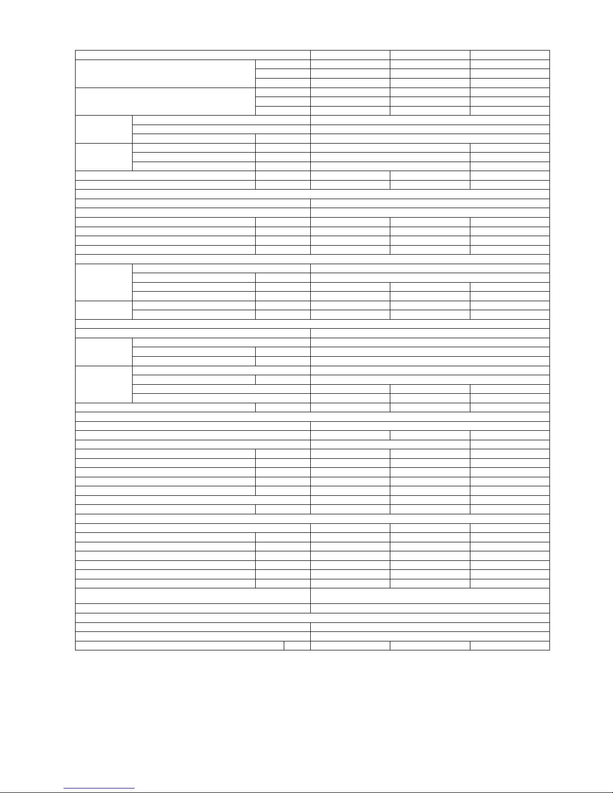
Heat Pump Unit (50Hz)
MODEL MAC030CR MAC035CR MAC040CR
Btu/hr 25,600 30,700 39,200
kcal/hr 6,450 7,740 9,890
NOMINAL COOLING CAPACITY
Watt 7,500 9,000 11,500
Btu/hr 27,300 32,400 42,700
kcal/hr 6,880 8,170 10,750
NOMINAL HEATING CAPACITY
Watt 8,000 9,500 12,500
MATERIAL Electro-galvanised Mild Steel
FINISH Polyester Power
CASING
THICKNESS mm 1
HEIGHT (H) mm (in) 1250 (49.2) 1560 (61.4)
WIDTH (W) mm (in) 841 (33.1) 927 (36.5)
TOTAL
UNIT
DIMENSION
DEPTH (D) mm (in) 382 (15) 406 (16)
NET WEIGHT kg 125 148 155
NOISE LEVEL dB(A) 58 58 60
EVAPOR ATOR
TYPE Brazed Plate Heat Exchanger
PLATE MATERIAL Stainless Steel
HEAT EXCHANGE AREA m2 0.7 0.8 1.1
NOMINAL WATER FLOW l/s 0.36 0.42 0.55
BPHE PRESSURE DROP VS NOMINAL FLOW RATE kPa 6.0 5.7 5.2
UNIT PRESSURE DROP WS NOMINAL FLOW RATE kPa 50 58 67
WATER LINE(HYDRAULIC KIT)
TYPE Horizontal Multistage End-Suction
POWER SUPPLY V/Ph/Hz 220 / 1 / 50
RUNNING CURRENT Amp 2.2 2.2 2.5
PUMP
WATER FLOW RATE GPM U.S. (l/s) 5.72 (0.36) 6.78 (0.42) 8.71 (0.55)
INSTALLATION PIPE CONNECTION mm (in) 34 ( Rc 1) 34 ( Rc 1) 34 ( Rc 1)
PIPING
HEAD m 25 24 24
CONDENSER COIL
TYPE
Cross Finned Tubes
MATERIAL Seamless Copper
WALL THICKNESS mm (in) 0.35 (0.014)
TUBE
OUTER DIAMETER mm (in) 9.52 (3/8)
MATERIAL Aluminium
THICKNESS mm (in) 0.127 (0.0005)
ROWS 2 2 2
FIN
FINS PER INCH 12 14 14
FACE AREA
m
2
(ft2) 0.78 (8.40) 0.78 (8.40) 1.23 (13.24)
CONDENSER FAN
TYPE/DRIVE Propeller/Direct
QUANTITY 1 1 1
BLADE MATERIAL Plastic Aluminium Alloy
BLADE DIAMETER mm (in) 460 (18.1) 460 (18.1) 600 (23.6)
POWER SUPPLY V/Ph/Hz 220 / 1 / 50 220 / 1 / 50 220 / 1 / 50
RATED RUNNING CURRENT Amp 1.8 1.8 0.9
RATED INPUT Watt 182 182 200
RATED OUTPUT Watt 100 100 120
MOTOR POLES 6 6 8
AIR VOLUME cmm/cfm 75 / 2650 75 / 2650 100 / 3530
COMPRESSOR
TYPE Scroll Scroll Scroll
POWER SUPPLY V/Ph/Hz 220 / 1 / 50 220 / 1 / 50 380 / 3 / 50
RATED RUNNING CURRENT (COOLING) Amp 10.8 15.1 7.6
RATED RUNNING CURRENT (HEATING) Amp 12.8 14.7 7.8
RATED INPUT (COOLING) Watt 2,200 3,300 3,910
RATED INPUT (HEATING) Watt 2,670 3,200 4,050
MAXIMUM STARTING CURRENT Amp 82 114 65.5
PROTECTION DEVICES
Overload and Discharge temp. Protection, Flow Switch and H/L Pressure
Switch
STAGE OF CAPACITY CONTROL On/Off
REFRIGERANT
TYPE R22
CONTROL Capillary Tube
CHARGING MASS kg 2.1 2.1 3.6
Notes:
1. All specifications are subjected to change by manufacturer without prior notice.
2. Nominal cooling values are based on entering/leaving chilled water temperature 12ºC/7ºC and air ambient temperature 35ºC.
3. Nominal heating values are based on entering/leaving hot water temperature 40ºC/45ºC and air ambient temperature 7ºC.
Page 12
Page 14

Heat Pump Unit (50Hz)
MODEL MAC050CR MAC065CR MAC070CR
Btu/hr 46,100 57,000 65,500
kcal/hr 11,610 14,360 16,510
NOMINAL COOLING CAPACITY
Watt 13,500 16,700 19,200
Btu/hr 49,500 65,500 71,000
kcal/hr 12,470 16,510 17,880
NOMINAL HEATING CAPACITY
Watt 14,500 19,200 20,800
MATERIAL Electro-galvanised Mild Steel
FINISH Polyester Power
CASING
THICKNESS mm 1
HEIGHT (H) mm (in) 1560 (61.4) 1700 (66.9)
WIDTH (W) mm (in) 927 (36.5) 1135 (44.7)
TOTAL
UNIT
DIMENSION
DEPTH (D) mm (in) 406 (16) 502 (19.7)
NET WEIGHT kg 160 230 245
NOISE LEVEL dB(A) 60 64 64
EVAPOR ATOR
TYPE Brazed Plate Heat Exchanger
PLATE MATERIAL Stainless Steel
HEAT EXCHANGE AREA m2 1.3 1.4 1.7
NOMINAL WATER FLOW l/s 0.64 0.79 0.91
BPHE PRESSURE DROP VS NOMINAL FLOW RATE kPa 5 34 36.5
UNIT PRESSURE DROP WS NOMINAL FLOW RATE kPa 75 92 110
WATER LINE(HYDRAULIC KIT)
TYPE Horizontal Multistage End-Suction
POWER SUPPLY V/Ph/Hz 220 / 1 / 50 380 / 3 / 50
RUNNING CURRENT Amp 2.5 1.3 1.3
PUMP
WATER FLOW RATE GPM U.S. (l/s) 10.21 (0.64) 12.63 (0.79) 14.53 (0.91)
INSTALLATION PIPE CONNECTION mm (in) 34 ( Rc 1) 34 ( Rc 1) 34 ( Rc 1)
PIPING
HEAD m 23 24 23
CONDENSER COIL
TYPE
Cross Finned Tubes
MATERIAL Seamless Copper
WALL THICKNESS mm (in) 0.35 (0.014)
TUBE
OUTER DIAMETER mm (in) 9.52 (3/8)
MATERIAL Aluminium
THICKNESS mm (in) 0.127 (0.0005)
ROWS 2 2 2
FIN
FINS PER INCH 14 14 14
FACE AREA
m
2
(ft2) 1.23 (13.24) 1.74 (18.73) 1.74 (18.73)
CONDENSER FAN
TYPE/DRIVE Propeller/Direct
QUANTITY 1 1 1
BLADE MATERIAL Aluminium Alloy
BLADE DIAMETER mm (in) 600 (23.6) 710 (28) 710 (28)
POWER SUPPLY V/Ph/Hz 220 / 1 / 50 220 / 1 / 50 220 / 1 / 50
RATED RUNNING CURRENT Amp 0.9 1.2 1.2
RATED INPUT Watt 200 250 250
RATED OUTPUT Watt 120 130 130
MOTOR POLES 8 10 10
AIR VOLUME cmm/cfm 100 / 3530 133 / 4700 133 / 4700
COMPRESSOR
TYPE Scroll Scroll Scroll
POWER SUPPLY V/Ph/Hz 380 / 3 / 50 380 / 3 / 50 380 / 3 / 50
RATED RUNNING CURRENT (COOLING) Amp 8.0 10.4 11.9
RATED RUNNING CURRENT (HEATING) Amp 8.0 11.4 11.5
RATED INPUT (COOLING) Watt 4,800 5,000 6,400
RATED INPUT (HEATING) Watt 4,820 5,700 6,100
MAXIMUM STARTING CURRENT Amp 74 101 95
PROTECTION DEVICES Overload Protection, Flow Switch and H/L Pressure Switch
STAGE OF CAPACITY CONTROL On/Off
REFRIGERANT
TYPE R22
CONTROL Capillary Tube
CHARGING MASS kg 3.8 5.15 7
Notes:
1. All specifications are subjected to change by manufacturer without prior notice.
2. Nominal cooling values are based on entering/leaving chilled water temperature 12ºC/7ºC and air ambient temperature 35ºC.
3. Nominal heating values are based on entering/leaving hot water temperature 40ºC/45ºC and air ambient temperature 7ºC.
Page 13
Page 15

Heat Pump Unit (50Hz)
MODEL MAC080CR MAC100CR
Btu/hr 76,800 92,100
kcal/hr 19,350 23,220
NOMINAL COOLING CAPACITY
Watt 22,500 27,000
Btu/hr 81,900 97,200
kcal/hr 20,640 24,510
NOMINAL HEATING CAPACITY
Watt 24,000 28,500
MATERIAL Electro-galvanised Mild Steel
FINISH Polyester Power
CASING
THICKNESS mm 1.0
HEIGHT (H) mm (in) 1260 (49.6)
WIDTH (W) mm (in) 1500 (59.1)
TOTAL
UNIT
DIMENSION
DEPTH (D) mm (in) 900 (35.4)
NET WEIGHT kg 350 360
NOISE LEVEL dB(A) 62 64
EVAPOR ATOR
TYPE Brazed Plate Heat Exchanger
PLATE MATERIAL Stainless Steel
HEAT EXCHANGE AREA m2 2.26 2.78
NOMINAL WATER FLOW (COOLING/HEATING) l/s 1.08/1.14 1.31/1.39
BPHE PRESSURE DROP VS NOMINAL FLOW RATE (C/H) kPa 74/72 82/80
UNIT PRESSURE DROP VS NOMINAL FLOW RATE kPa 104 121
WATER LINE(HYDRAULIC KIT)
TYPE Horizontal Multistage End-Suction
POWER SUPPLY V/Ph/Hz 380 / 3 / 50
RUNNING CURRENT Amp 1.1 1.1
PUMP
WATER FLOW RATE ( C / H ) GPM U.S. (l/s) 17.17(1.08)/18.05(1.14) 20.70(1.31)/22.02(1.39)
INSTALLATION PIPE CONNECTION mm (in) 42 (Rc 1-1/4) 42 (Rc 1-1/4)
PIPING
HEAD (C / H) m 26/25 23.5/22.5
MATERIAL Steel EXPANSION
TANK
CAPACITY / VOLUME litres 8 8
CONDENSER COIL
TYPE
Cross Finned Tubes
MATERIAL Seamless Copper
WALL THICKNESS mm (in) 0.35 (0.014)
TUBE
OUTER DIAMETER mm (in) 9.52 (3/8)
MATERIAL Aluminium
THICKNESS mm (in) 0.127 (0.0005)
ROWS 2 2
FIN
FINS PER INCH 14 14
FACE AREA
m
2
(ft2) 2.5 (26.9) 2.5 (26.9)
CONDENSER FAN
TYPE/DRIVE Propeller/Direct
QUANTITY 2 2
BLADE MATERIAL Aluminium
BLADE DIAMETER mm (in) 600 (23.6) 600 (23.6)
POWER SUPPLY V/Ph/Hz 220 / 1 / 50 220 / 1 / 50
RATED RUNNING CURRENT Amp 0.9*2 0.9*2
RATED INPUT Watt 120*2 120*2
RATED OUTPUT Watt 200*2 200*2
MOTOR POLES 8 8
AIR VOLUME cmm/cfm 100*2 / 3530*2 100*2 / 3530*2
COMPRESSOR
TYPE Scroll Scroll
POWER SUPPLY V/Ph/Hz 380 / 3 / 50 380 / 3 / 50
RATED RUNNING CURRENT (COOLING) Amp 7.3*2 8.6*2
RATED RUNNING CURRENT (HEATING) Amp 7.3*2 8.6*2
RATED INPUT (COOLING) Watt 3,900*2 4,800*2
RATED INPUT (HEATING) Watt 3,900*2 4,800*2
MAXIMUM STARTING CURRENT Amp 40 48
PROTECTION DEVICES Overload Protection, Flow Switch & H/L Pressure Switch
STAGE OF CAPACITY CONTROL (%) 0-50-100
REFRIGERANT
TYPE R22
CONTROL Capillary Tube
CHARGING MASS kg 4.0*2 4.6*2
Notes:
1. All specifications are subjected to change by manufacturer without prior notice.
2. Nominal cooling values are based on entering/leaving chilled water temperature 12ºC/7ºC and air ambient temperature 35ºC.
3. Nominal heating values are based on entering/leaving hot water temperature 40ºC/45ºC and air ambient temperature 7ºC.
Page 14
Page 16

Heat Pump Unit (50Hz)
MODEL MAC120CR MAC150CR
Btu/hr 112,600 129,700
kcal/hr 28,380 32,670
NOMINAL COOLING CAPACITY
Watt 33,000 38,000
Btu/hr 119,400 136,500
kcal/hr 30,090 34,390
NOMINAL HEATING CAPACITY
Watt 35,000 40,000
MATERIAL Electro-galvanised Mild Steel
FINISH Polyester Power
CASING
THICKNESS mm 1
HEIGHT (H) mm (in) 1260 (49.6)
WIDTH (W) mm (in) 1800 (70.9)
TOTAL UNIT DIMENSION
DEPTH (D) mm (in) 1150 (45.3)
NET WEIGHT kg 480 560
NOISE LEVEL dB(A) 67 70
EVAPOR ATOR
TYPE Brazed Plate Heat Exchanger
PLATE MATERIAL Stainless Steel
HEAT EXCHANGE AREA m2 3.0 3.6
NOMINAL WATER FLOW (COOLING/HEATING) l/s 1.67/1.78 2.0/2.11
BPHE PRESSURE DROP VS NOMINAL FLOW RATE (C/H) kPa 76/74 75/73
UNIT PRESSURE DROP VS NOMINAL FLOW RATE kPa 138 155
WATER LINE(HYDRAULIC KIT)
TYPE Horizontal Multistage End-Suction
POWER SUPPLY V/Ph/Hz 380 / 3 / 50
RUNNING CURRENT Amp 2.5 2.5
PUMP
WATER FLOW RATE ( C / H ) GPM U.S. (l/s) 26.42(1.67)/28.18(1.78) 31.70(2.0)/33.47(2.11)
INSTALLATION PIPE
CONNECTION
mm (in) 42 (Rc 1-1/4) 42 (Rc 1-1/4)
PIPING
HEAD (C / H) m 31/29 28/26
MATERIAL Steel
EXPANSION
TANK
CAPACITY / VOLUME litres 8 8
CONDENSER COIL
TYPE Cross Finned Tubes
MATERIAL Seamless Copper
WALL THICKNESS mm (in) 0.35 (0.014)
TUBE
OUTER DIAMETER mm (in) 9.52 (3/8)
MATERIAL Aluminium
THICKNESS mm (in) 0.127 (0.0005)
ROWS 2 2
FIN
FINS PER INCH 14 14
FACE AREA m2 (ft2) 2.5 (26.9) 2.5 (26.9)
CONDENSER FAN
TYPE/DRIVE Propeller/Direct
QUANTITY 2 2
BLADE MATERIAL
BLADE DIAMETER mm (in) 660 (26) 660 (26)
POWER SUPPLY V/Ph/Hz 380 / 3 / 50
RATED RUNNING CURRENT Amp 0.86*2 4.5*2
RATED INPUT Watt 200*2 450*2
RATED OUTPUT Watt 470*2 820*2
MOTOR POLES 8 6
AIR VOLUME cmm/cfm 142*2 / 5000*2 142*2 / 5000*2
COMPRESSOR
TYPE Scroll Scroll
POWER SUPPLY V/Ph/Hz 380 / 3 / 50 380 / 3 / 50
RATED RUNNING CURRENT (COOLING) Amp 10.3*2 11.5*2
RATED RUNNING CURRENT (HEATING) Amp 10.3*2 11.5*2
RATED INPUT (COOLING) Watt 5,300*2 6,240*2
RATED INPUT (HEATING) Watt 5,300*2 6,240*2
MAXIMUM STARTING CURRENT Amp 55 62
PROTECTION DEVICES Overload Protection, Flow Switch & H/L Pressure Switch
STAGE OF CAPACITY CONTROL (%) 0-50-100
REFRIGERANT
TYPE R22
CONTROL Capillary Tube
CHARGING MASS kg 7.5*2 6.8*2
Notes:
1. All specifications are subjected to change by manufacturer without prior notice.
2. Nominal cooling values are based on entering/leaving chilled water temperature 12ºC/7ºC and air ambient temperature 35ºC.
3. Nominal heating values are based on entering/leaving hot water temperature 40ºC/45ºC and air ambient temperature 7ºC.
Page 15
Page 17

Performance Characteristic Charts
Actual performance can be determined by conducting correction after looking up the following charts.
Based on the ambient temperature and desired return water temperature, we can locate the corresponding
performance factor in these charts, then the corresponding actual cooling (heating) capacity and power input
can be determined by using the following formula.
Actual cooling (heating) capacity = nominal cooling (heating) capacity * cooling (heating) performance
correction factor
Actual power input = nominal power input * power input correction factor.
Page 16
Page 18

Cooling Only
Models: MAC 030 / 035 / 040 / 050 / 065 / 070 / 080 / 100 / 120 / 150 C
Cooling
Capacity W
Power
Input W
Cooling
Capacity W
Power
Input W
Cooling
Capacity W
Power
Input W
Cooling
Capacity W
Power
Input W
Cooling
Capacity W
Power
Input W
5 7313 1985 6915 2085 6773 2257 6353 2478 6113 2725
6 7553 2296 7260 2421 7200 2619 6930 2760 6758 3048
7 7793 2549 7605 2744 7500 3202 7245 3314 7088 3394
8 8298 2943 7898 3096 7763 3429 7403 3545 7260 3602
9 8348 3375 8168 3525 8040 3737 7628 3855 7485 4009
10 8648 3583 8505 3900 8288 4083 7770 4195 7628 4457
5 8775 2363 8298 2482 8127 2687 7623 2950 7335 3244
6 9063 2733 8712 2882 8640 3118 8316 3286 8109 3629
7 9351 3034 9126 3267 9000 3812 8694 3945 8505 4041
8 9958 3503 9477 3686 9315 4083 8883 4220 8712 4289
9 10017 4018 9801 4197 9648 4449 9153 4590 8982 4773
10 10377 4266 10206 4643 9945 4860 9324 4994 9153 5306
5 11213 2784 10603 2923 10385 3165 9741 3475 9373 3821
6 11581 3219 11132 3394 11040 3673 10626 3870 10362 4274
7 11949 3574 11661 3848 11500 4490 11109 4647 10868 4759
8 12724 4126 12110 4342 11903 4809 11351 4970 11132 5051
9 12800 4732 12524 4943 12328 5240 11696 5406 11477 5621
10 13260 5024 13041 5469 12708 5725 11914 5882 11696 6250
5 13163 3311 12447 3476 12191 3765 11435 4133 11003 4544
6 13595 3829 13068 4037 12960 4368 12474 4603 12164 5084
7 14027 4251 13689 4576 13500 5340 13041 5527 12758 5660
8 14937 4907 14216 5164 13973 5719 13325 5911 13068 6008
9 15026 5628 14702 5879 14472 6232 13730 6429 13473 6686
10 15566 5975 15309 6504 14918 6809 13986 6995 13730 7433
5 16283 4058 15397 4261 15080 4614 14145 5066 13611 5570
6 16817 4693 16166 4948 16032 5354 15431 5642 15047 6231
7 17351 5210 16934 5609 16700 6545 16132 6774 15782 6938
8 18477 6015 17585 6329 17285 7010 16483 7245 16166 7363
9 18587 6898 18186 7206 17902 7638 16984 7880 16667 8194
10 19255 7324 18938 7972 18454 8345 17301 8574 16984 9111
5 18720 4492 17702 4716 17338 5108 16262 5608 15648 6165
6 19334 5195 18586 5477 18432 5926 17741 6245 17299 6897
7 19949 5767 19469 6209 19200 7245 18547 7499 18144 7680
8 21243 6658 20218 7006 19872 7759 18950 8020 18586 8151
9 21370 7636 20909 7977 20582 8455 19526 8723 19162 9071
10 22138 8107 21773 8824 21216 9237 19891 9491 19526 10085
5 21938 5571 20745 5849 20318 6334 19058 6954 18338 7646
6 22658 6442 21780 6793 21600 7350 20790 7745 20273 8554
7 23378 7152 22815 7700 22500 8985 21735 9299 21263 9524
8 24894 8257 23693 8688 23288 9623 22208 9946 21780 10108
9 25043 9470 24503 9892 24120 10485 22883 10818 22455 11249
10 25943 10054 25515 10944 24863 11456 23310 11770 22883 12507
5 26325 6625 24894 6956 24381 7533 22869 8270 22005 9093
6 27189 7661 26136 8078 25920 8740 24948 9210 24327 10172
7 28053 8505 27378 9157 27000 10685 26082 11059 25515 11326
8 29873 9820 28431 10332 27945 11444 26649 11828 26136 12021
9 30051 11262 29403 11764 28944 12469 27459 12865 26946 13378
10 31131 11957 30618 13014 29835 13623 27972 13997 27459 14874
5 34125 7955 32270 8352 31605 9045 29645 9930 28525 10918
6 35245 9199 33880 9699 33600 10495 32340 11059 31535 12214
7 36365 10213 35490 10995 35000 12830 33810 13279 33075 13600
8 38725 11791 36855 12407 36225 13741 34545 14203 33880 14434
9 38955 13523 38115 14126 37520 14973 35595 15447 34930 16063
10 40355 14357 39690 15627 38675 16358 36260 16807 35595 17859
5 34125 9219 32270 9680 31605 10483 29645 11509 28525 12654
6 35245 10662 33880 11242 33600 12164 32340 12818 31535 14156
7 36365 11837 35490 12744 35000 14870 33810 15390 33075 15762
8 38725 13666 36855 14379 36225 15926 34545 16461 33880 16729
9 38955 15673 38115 16372 37520 17353 35595 17903 34930 18617
10 40355 16640 39690 18112 38675 18959 36260 19480 35595 20699
MAC120C
MAC150C
MAC065C
MAC070C
MAC080C
MAC100C
MAC030C
MAC035C
MAC040C
MAC050C
Model
Leaving
Water
Temp.
o
C
Environment Temperature
o
C
28
o
C
32
o
C
35
o
C
40
o
C
42
o
C
Page 17
Page 19

Heating Mode
Models: MAC 030 / 035 / 040 / 050 / 065 / 070 / 080 / 100 / 120 / 150 CR
Cooling
Capacity W
Power
Input W
Cooling
Capacity W
Power
Input W
Cooling
Capacity W
Power
Input W
Cooling
Capacity W
Power
Input W
Cooling
Capacity W
Power
Input W
5 7313 1953 6915 2261 6773 2632 6353 2690 6113 2831
6 7553 2101 7260 2389 7200 2968 6930 3026 6758 3336
7 7793 2171 7605 2469 7500 3202 7245 3340 7088 3653
8 8298 2498 7898 2686 7763 3369 7403 3481 7260 3874
9 8348 2770 8168 3026 8040 3509 7628 3650 7485 4191
10 8648 2975 8505 3180 8288 3653 7770 3794 7628 4502
5 8775 2325 8298 2691 8127 3133 7623 3202 7335 3370
6 9063 2501 8712 2844 8640 3534 8316 3602 8109 3972
7 9351 2585 9126 2939 9000 3812 8694 3976 8505 4349
8 9958 2973 9477 3198 9315 4010 8883 4144 8712 4613
9 10017 3297 9801 3602 9648 4178 9153 4346 8982 4990
10 10377 3541 10206 3785 9945 4349 9324 4517 9153 5360
5 11213 2739 10603 3170 10385 3691 9741 3772 9373 3969
6 11581 2945 11132 3350 11040 4162 10626 4243 10362 4679
7 11949 3044 11661 3462 11500 4490 11109 4683 10868 5123
8 12724 3502 12110 3767 11903 4723 11351 4881 11132 5433
9 12800 3884 12524 4243 12328 4921 11696 5119 11477 5877
10 13260 4171 13041 4459 12708 5123 11914 5321 11696 6313
5 13163 3257 12447 3770 12191 4389 11435 4486 11003 4721
6 13595 3503 13068 3984 12960 4950 12474 5046 12164 5564
7 14027 3621 13689 4117 13500 5340 13041 5570 12758 6093
8 14937 4165 14216 4480 13973 5618 13325 5805 13068 6461
9 15026 4619 14702 5046 14472 5853 13730 6088 13473 6990
10 15566 4961 15309 5303 14918 6093 13986 6328 13730 7508
5 16283 3992 15397 4621 15080 5380 14145 5498 13611 5786
6 16817 4294 16166 4883 16032 6067 15431 6185 15047 6820
7 17351 4438 16934 5046 16700 6545 16132 6826 15782 7468
8 18477 5105 17585 5491 17285 6885 16483 7114 16166 7919
9 18587 5661 18186 6185 17902 7173 16984 7461 16667 8567
10 19255 6080 18938 6499 18454 7468 17301 7756 16984 9202
5 18720 4419 17702 5115 17338 5955 16262 6086 15648 6405
6 19334 4753 18586 5405 18432 6716 17741 6847 17299 7549
7 19949 4912 19469 5586 19200 7245 18547 7557 18144 8267
8 21243 5651 20218 6079 19872 7622 18950 7875 18586 8766
9 21370 6267 20909 6847 20582 7941 19526 8259 19162 9484
10 22138 6731 21773 7194 21216 8267 19891 8585 19526 10186
5 21938 5481 20745 6343 20318 7386 19058 7547 18338 7943
6 22658 5894 21780 6703 21600 8329 20790 8491 20273 9362
7 23378 6092 22815 6927 22500 8985 21735 9371 21263 10252
8 24894 7008 23693 7538 23288 9452 22208 9767 21780 10872
9 25043 7772 24503 8491 24120 9848 22883 10243 22455 11761
10 25943 8347 25515 8922 24863 10252 23310 10647 22883 12633
5 26325 6518 24894 7544 24381 8783 22869 8975 22005 9446
6 27189 7009 26136 7971 25920 9905 24948 10097 24327 11134
7 28053 7244 27378 8238 27000 10685 26082 11144 25515 12192
8 29873 8334 28431 8965 27945 11241 26649 11615 26136 12929
9 30051 9243 29403 10097 28944 11711 27459 12181 26946 13987
10 31131 9926 30618 10610 29835 12192 27972 12662 27459 15023
5 34125 7826 32270 9058 31605 10546 29645 10777 28525 11342
6 35245 8416 33880 9571 33600 11893 32340 12124 31535 13369
7 36365 8699 35490 9892 35000 12830 33810 13382 33075 14639
8 38725 10007 36855 10764 36225 13497 34545 13946 33880 15524
9 38955 11098 38115 12124 37520 14062 35595 14626 34930 16794
10 40355 11919 39690 12740 38675 14639 36260 15204 35595 18039
5 34125 9071 32270 10498 31605 12223 29645 12491 28525 13145
6 35245 9755 33880 11093 33600 13784 32340 14052 31535 15495
7 36365 10082 35490 11465 35000 14870 33810 15509 33075 16967
8 38725 11599 36855 12476 36225 15643 34545 16164 33880 17993
9 38955 12863 38115 14052 37520 16298 35595 16952 34930 19465
10 40355 13814 39690 14766 38675 16967 36260 17621 35595 20907
MAC120CR
MAC150CR
Model
Leaving
Water
Temp.
o
C
42
o
C
MAC030CR
MAC035CR
MAC040CR
28
o
C
32
o
C
35
o
C
40
o
C
MAC050CR
MAC065CR
MAC070CR
MAC080CR
MAC100CR
Environment Temperature
o
C
Page 18
Page 20

Heating Mode
Models: MAC 030 / 035 / 040 / 050 / 065 / 070 / 080 / 100 / 120 / 150 CR
Heating
Capacity W
Power Input WHeating
Capacity W
Power Input WHeating
Capacity W
Power Input WHeating
Capacity W
Power Input WHeating
Capacity W
Power Input WHeating
Capacity W
Power Input
W
35 6552 2350 7144 2459 7712 2690 8448 2859 8656 2943 8840 3023
40 6200 2478 6816 2651 7408 2815 8176 3048 8360 3074 8560 3228
45 5824 2645 6496 2779 7160 2930 8000 3202 8136 3269 8344 3340
50 5712 2693 6288 2805 6864 3071 7736 3269 7960 3295 8144 3394
55 5488 2738 6032 2872 6592 3196 7512 3394 7680 3433 7840 3487
35 7781 2798 8484 2928 9158 3202 10032 3404 10279 3503 10498 3599
40 7363 2950 8094 3156 8797 3351 9709 3629 9928 3660 10165 3842
45 6916 3149 7714 3309 8503 3488 9500 3812 9662 3891 9909 3976
50 6783 3206 7467 3339 8151 3656 9187 3892 9453 3923 9671 4041
55 6517 3259 7163 3419 7828 3804 8921 4041 9120 4086 9310 4151
35 10238 3296 11163 3448 12050 3772 13200 4010 13525 4126 13813 4239
40 9688 3475 10650 3718 11575 3947 12775 4274 13063 4310 13375 4526
45 9100 3709 10150 3897 11188 4108 12500 4490 12713 4583 13038 4683
50 8925 3776 9825 3933 10725 4306 12088 4584 12438 4620 12725 4759
55 8575 3839 9425 4028 10300 4481 11738 4759 12000 4813 12250 4890
35 11876 3920 12949 4101 13978 4486 15312 4769 15689 4907 16023 5041
40 11238 4133 12354 4422 13427 4694 14819 5084 15153 5126 15515 5383
45 10556 4411 11774 4635 12978 4886 14500 5340 14747 5451 15124 5570
50 10353 4491 11397 4678 12441 5121 14022 5452 14428 5495 14761 5660
55 9947 4566 10933 4790 11948 5329 13616 5660 13920 5724 14210 5815
35 14742 4804 16074 5027 17352 5498 19008 5845 19476 6015 19890 6178
40 13950 5066 15336 5419 16668 5753 18396 6231 18810 6283 19260 6597
45 13104 5406 14616 5681 16110 5989 18000 6545 18306 6681 18774 6826
50 12852 5504 14148 5733 15444 6277 17406 6682 17910 6735 18324 6938
55 12348 5596 13572 5871 14832 6532 16902 6938 17280 7016 17640 7128
35 17199 5318 18753 5564 20244 6086 22176 6470 22722 6658 23205 6839
40 16275 5608 17892 5999 19446 6368 21462 6897 21945 6955 22470 7303
45 15288 5984 17052 6289 18795 6629 21000 7245 21357 7396 21903 7557
50 14994 6093 16506 6347 18018 6948 20307 7397 20895 7455 21378 7680
55 14406 6194 15834 6499 17304 7231 19719 7680 20160 7767 20580 7890
35 19656 6595 21432 6900 23136 7547 25344 8024 25968 8257 26520 8482
40 18600 6954 20448 7440 22224 7898 24528 8554 25080 8626 25680 9057
45 17472 7422 19488 7799 21480 8221 24000 8985 24408 9172 25032 9371
50 17136 7556 18864 7871 20592 8617 23208 9174 23880 9246 24432 9524
55 16464 7682 18096 8060 19776 8967 22536 9524 23040 9632 23520 9785
35 23342 7843 25451 8206 27474 8975 30096 9542 30837 9820 31493 10087
40 22088 8270 24282 8847 26391 9392 29127 10172 29783 10258 30495 10770
45 20748 8826 23142 9275 25508 9777 28500 10685 28985 10907 29726 11144
50 20349 8986 22401 9360 24453 10247 27560 10909 28358 10995 29013 11326
55 19551 9136 21489 9584 23484 10664 26762 11326 27360 11454 27930 11636
35 30303 9417 33041 9853 35668 10777 39072 11457 40034 11791 40885 12112
40 28675 9930 31524 10623 34262 11278 37814 12214 38665 12317 39590 12933
45 26936 10598 30044 11136 33115 11739 37000 12830 37629 13097 38591 13382
50 26418 10790 29082 11239 31746 12304 35779 13099 36815 13202 37666 13600
55 25382 10970 27898 11509 30488 12804 34743 13600 35520 13754 36260 13972
35 30303 10915 33041 11420 35668 12491 39072 13279 40034 13666 40885 14037
40 28675 11509 31524 12312 34262 13071 37814 14156 38665 14275 39590 14989
45 26936 12283 30044 12907 33115 13606 37000 14870 37629 15179 38591 15509
50 26418 12506 29082 13026 31746 14260 35779 15182 36815 15301 37666 15762
55 25382 12714 27898 13338 30488 14840 34743 15762 35520 15941 36260 16193
0ºC-5ºC
Leaving
Water Temp.
o
C
Environment Temperature
o
C
15ºC10ºC7ºC4ºC
MAC050CR
MAC100CR
MAC120CR
MAC150CR
MAC065CR
MAC070CR
MAC080CR
MAC030CR
MAC035CR
MAC040CR
Model
Page 19
Page 21

Technical Data
Correction Factors With Glycol Use
GLYCOL % COOLING CAPACITY WATER FLOW PRESSURE DROP
10 0.990 1.015 1.06
20 0.980 1.040 1.12
30 0.970 1.080 1.18
40 0.965 1.135 1.24
Water Pressure Drop And Flow Rate
Water Flow Rate Water Pressure Drop
MODEL
L/s m³/h kPa Bar
MAC080C
1.08 3.9 74 0.74
MAC100C
1.31 4.7 82 0.82
MAC120C
1.67 6.0 76 0.76
MAC150C
2.0 7.2 74 0.74
Cooling
1.08 3.9 74 0.74
MAC080CR
Heating
1.14 4.1 72 0.72
Cooling
1.31 4.7 82 0.82
MAC100CR
Heating
1.39 5.0 80 0.80
Cooling
1.67 6.0 76 0.76
MAC120CR
Heating
1.78 6.4 74 0.74
Cooling
2.0 7.2 75 0.45
MAC150CR
Heating
2.11 7.6 73 0.73
Page 20
Page 22

Outlines and Dimensions
Model: MAC 030C(R)/035C(R)/040C(R)/050C(R)/065C(R)/070C(R)
UNIT: mm
A B C D E
MAC030/035C(R)
922 382 1250 841 882
MAC040/050C(R)
1004 406 1560 927 970
MAC065/070C(R)
1212 502 1700 1135 1162
F G H I J
MAC030/035C(R)
86 231.5 90 75 531.5
MAC040/050C(R)
80 267 167.5 124.5 556
MAC065/070C(R)
132 254 235 80 604.5
2- Rc 1
4- 10X20
Page 21
Page 23
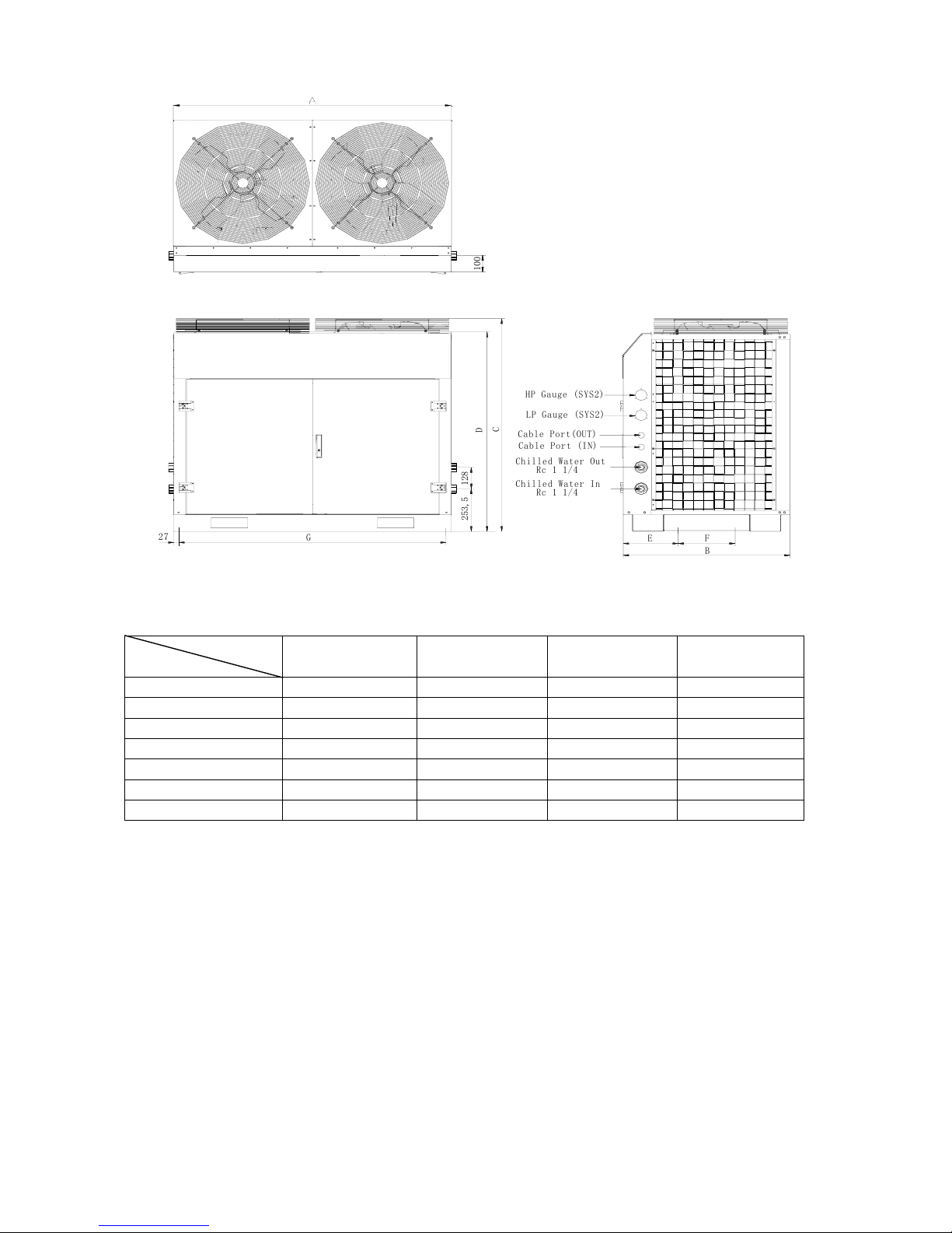
Model: MAC 080C(R)/100C(R)/120C(R)/150C(R)
2
7
G
E
2
5
3
,
5
1
2
8
D
C
HP Gauge (SYS2)
LP Gauge (SYS2)
Cable Port(OUT)
Chilled Water Out
Cable Port (IN)
F
B
1
0
0
Rc 1 1/
4
Chilled Water I
n
Rc 1 1/
4
UNIT: mm
Model
Dimension
MAC080C(R) MAC100C(R) MAC120C(R) MAC150C(R)
A
1500 1500 1800 1800
B
900 900 1150 1150
C
1260 1260 1260 1260
D
1190 1190 1190 1190
E
297.5 297.5 347.5 347.5
F(Mounting hole)
307.5 307.5 307.5 307.5
G(Mounting hole)
1446 1446 1546 1546
Page 22
Page 24

Accessory Hydraulic Kit
For MAC080C(R) to MAC150C(R), accessory hydraulic kit consists of 40L capacity stainless steel water
storage tank, safety valve, dirt drainage valve, and auto air vent valve etc. For MAC030C(R) to
MAC070C(R), with 8L volume water expansion chamber additionally.
Water Drainage Port DN2
5
Chilled Water Out R
1
Chilled Water In R
1
Dirt Drainage Port R1/
2
4-10x20
Page 23
Page 25

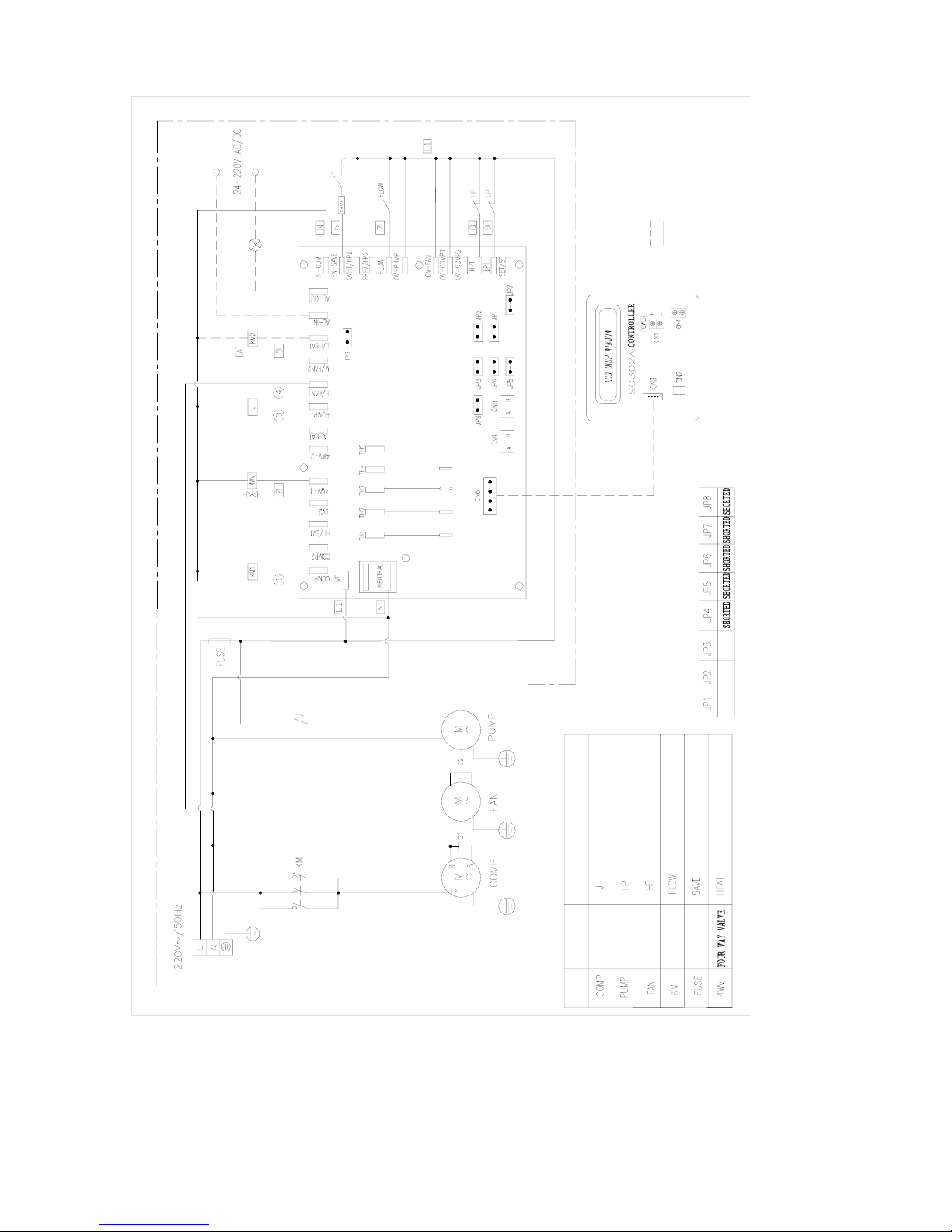
Wiring Diagrams
Model: MAC030/035C
W
A
T
E
R
F
L
O
W
S
W
I
T
C
H
T
W
O
W
A
Y
V
A
L
V
E
I
N
T
E
R
L
O
C
K
R
E
L
A
Y
C
O
M
P
.
L
O
W
P
R
E
S
S
U
R
E
S
W
I
T
C
H
W
H
I
T
E
C
O
M
P
.
H
I
G
H
P
R
E
S
S
U
R
E
S
W
I
T
C
H
S
Y
M
B
O
L
R
E
D
B
L
U
E
B
L
U
E
W
A
T
E
R
P
U
M
P
D
E
S
C
R
I
P
T
I
O
N
C
O
M
P
R
E
S
S
O
R
F
A
N
S
Y
M
B
O
L
F
U
S
E
(
1
0
A
)
C
O
N
T
A
C
T
O
R
J
U
M
P
E
R
S
S
E
T
T
I
N
G
:
W
H
I
T
E
B
L
A
C
K
B
L
U
E
R
E
D
B
L
U
E
R
E
D
D
E
S
C
R
I
P
T
I
O
N
R
E
TUR
N WAT
E
R
TE
M
P.
SENSO
R
S
U
P
PLY W
A
T
E
R T
E
MP.
SEN
S
O
R
A
L
A
R
M
I
N
D
I
C
A
T
O
R
C
O
N
T
R
O
L
M
O
D
U
L
E
R
E
TUR
N AIR
T
E
MP.
SENS
O
R
M
C
H
0
3
A
O
P
E
N
3
、
W
h
e
n
J
P
6
b
e
i
n
g
c
l
o
s
e
d
,
2
、
F
a
c
t
o
r
y
W
i
r
e
d
1
、
F
i
e
l
d
W
i
r
i
n
g
;
N
O
T
E
S
:
f
u
n
c
t
i
o
n
w
i
l
l
b
e
i
n
a
c
t
i
v
a
t
e
d
t
h
e
t
w
o
w
a
y
v
a
l
v
e
i
n
t
e
r
l
o
c
k
D
r
a
w
i
n
g
N
O
.
:
M
0
8
0
2
4
3
2
5
0
4
6
O
P
E
N
O
P
E
N
O
P
E
N
O
P
E
N
Page 24
Page 26
Model: MAC030/035CR
R
E
D
B
L
U
E
B
L
U
E
R
E
D
B
L
U
E
R
E
D
B
L
U
E
W
H
I
T
E
B
L
A
C
K
W
H
I
T
E
D
E
F
R
O
S
T
I
N
G
T
E
M
P
.
S
E
N
S
O
R
R
E
T
U
R
N
A
I
R
T
E
M
P
.
S
E
N
S
O
R
S
U
P
P
L
Y
W
A
T
E
R
T
E
M
P
.
S
E
N
S
O
R
R
E
T
U
R
N
W
A
T
E
R
T
E
M
P
.
S
E
N
S
O
R
A
L
A
R
M
I
N
D
I
C
A
T
O
R
C
O
N
T
R
O
L
M
O
D
U
L
E
M
C
H
0
3
A
R
E
L
A
Y
C
O
M
P
.
L
O
W
P
R
E
S
S
U
R
E
S
W
I
T
C
H
C
O
M
P
.
H
I
G
H
P
R
E
S
S
U
R
E
S
W
I
T
C
H
W
A
T
E
R
F
L
O
W
S
W
I
T
C
H
T
W
O
W
A
Y
V
A
L
V
E
I
N
T
E
R
L
O
C
K
S
Y
M
B
O
L
D
E
S
C
R
I
P
T
I
O
N
S
Y
M
B
O
L
D
E
S
C
R
I
P
T
I
O
N
C
O
M
P
R
E
S
S
O
R
W
A
T
E
R
P
U
M
P
F
A
N
C
O
N
T
A
C
T
O
R
F
U
S
E
(
1
0
A
)
J
U
M
P
E
R
S
S
E
T
T
I
N
G
:
A
U
X
I
L
I
A
R
Y
H
E
A
T
E
R
O
P
E
N
O
P
E
N
O
P
E
N
D
r
a
w
i
n
g
N
O
.
:
M
0
8
0
2
4
3
2
5
0
4
5
3
、
W
h
e
n
J
P
6
b
e
i
n
g
c
l
o
s
e
d
,
2
、
F
a
c
t
o
r
y
W
i
r
e
d
1
、
F
i
e
l
d
W
i
r
i
n
g
;
N
O
T
E
S
:
f
u
n
c
t
i
o
n
w
i
l
l
b
e
i
n
a
c
t
i
v
a
t
e
d
t
h
e
t
w
o
w
a
y
v
a
l
v
e
i
n
t
e
r
l
o
c
k
Page 25
Page 27

Model: MAC040/050C
R
E
T
U
R
N
A
I
R
T
E
M
P
.
S
E
N
S
O
R
S
U
P
P
L
Y
W
A
T
E
R
T
E
M
P
.
S
E
N
S
O
R
R
E
T
U
R
N
W
A
T
E
R
T
E
M
P
.
S
E
N
S
O
R
Y
E
L
.
R
E
D
B
L
A
C
K
R
E
D
B
L
A
C
K
B
L
U
E
Y
E
L
.
C
O
N
T
R
O
L
M
O
D
U
L
E
M
C
H
0
3
A
A
L
A
R
M
I
N
D
I
C
A
T
O
R
R
E
L
A
Y
A
M
P
S
T
H
E
R
M
A
L
O
V
E
R
L
O
A
D
1
0
.
5
A
S
Y
M
B
O
L
S
Y
M
B
O
L
D
E
S
C
R
I
P
T
I
O
N
C
O
M
P
R
E
S
S
O
R
W
H
I
T
E
S
Y
M
B
O
L
D
E
S
C
R
I
P
T
I
O
N
R
E
L
A
Y
D
E
S
C
R
I
P
T
I
O
N
C
A
P
A
C
I
T
O
R
F
A
N
M
O
T
O
R
W
A
T
E
R
P
U
M
P
C
O
N
T
A
C
T
O
R
W
A
T
E
R
F
L
O
W
S
W
I
T
C
H
M
A
C
0
5
0
C
F
U
S
E
(
1
0
A
)
M
A
C
0
4
0
C
M
O
D
E
L
N
O
T
E
S
:
O
P
E
N
J
U
M
P
E
R
S
S
E
T
T
I
N
G
:
9
.
6
A
D
r
a
w
i
n
g
N
O
.
:
M
0
8
0
2
4
3
2
5
0
7
6
f
u
n
c
t
i
o
n
w
i
l
l
b
e
i
n
v
a
l
i
d
a
t
e
d
1
、
F
i
e
l
d
W
i
r
i
n
g
;
2
、
F
a
c
t
o
r
y
W
i
r
e
d
3
、
W
h
e
n
J
P
6
b
e
i
n
g
c
l
o
s
e
d
,
t
h
e
t
w
o
w
a
y
v
a
l
v
e
i
n
t
e
r
l
o
c
k
O
P
E
N
O
P
E
N
O
P
E
N
O
P
E
N
Page 26
Page 28

Model: MAC040/050CR
D
E
F
R
O
S
T
I
N
G
T
E
M
P
.
S
E
N
S
O
R
R
E
T
U
R
N
A
I
R
T
E
M
P
.
S
E
N
S
O
R
S
U
P
P
L
Y
W
A
T
E
R
T
E
M
P
.
S
E
N
S
O
R
R
E
T
U
R
N
W
A
T
E
R
T
E
M
P
.
S
E
N
S
O
R
Y
E
L
.
R
E
D
B
L
A
C
K
R
E
D
B
L
U
E
B
L
A
C
K
Y
E
L
.
C
O
N
T
R
O
L
M
O
D
U
L
E
M
C
H
0
3
A
A
L
A
R
M
I
N
D
I
C
A
T
O
R
1
0
.
5
A
S
Y
M
B
O
L
D
E
S
C
R
I
P
T
I
O
N
S
Y
M
B
O
L
D
E
S
C
R
I
P
T
I
O
N
C
O
M
P
R
E
S
S
O
R
W
H
I
T
E
S
Y
M
B
O
L
R
E
L
A
Y
D
E
S
C
R
I
P
T
I
O
N
C
A
P
A
C
I
T
O
R
F
A
N
M
O
T
O
R
W
A
T
E
R
P
U
M
P
C
O
N
T
A
C
T
O
R
F
U
S
E
(
1
0
A
)
A
U
X
I
L
I
A
R
Y
H
E
A
T
E
R
M
A
C
0
5
0
C
R
C
O
M
P
.
H
I
G
H
P
R
E
S
S
U
R
E
S
W
I
T
C
H
C
O
M
P
.
L
O
W
P
R
E
S
S
U
R
E
S
W
I
T
C
H
M
O
D
E
L
M
A
C
0
4
0
C
R
N
O
T
E
S
:
O
P
E
N
O
P
E
N
O
P
E
N
O
P
E
N
O
P
E
N
J
U
M
P
E
R
S
S
E
T
T
I
N
G
:
9
.
6
A
D
r
a
w
i
n
g
N
O
.
:
M
0
8
0
2
4
3
2
5
0
7
2
f
u
n
c
t
i
o
n
w
i
l
l
b
e
i
n
a
c
t
i
v
a
t
e
d
t
h
e
t
w
o
w
a
y
v
a
l
v
e
i
n
t
e
r
l
o
c
k
1
、
F
i
e
l
d
W
i
r
i
n
g
;
2
、
F
a
c
t
o
r
y
W
i
r
e
d
3
、
W
h
e
n
J
P
6
b
e
i
n
g
c
l
o
s
e
d
,
T
H
E
R
M
A
L
O
V
E
R
L
O
A
D
R
E
L
A
Y
A
M
P
S
Page 27
Page 29

Model: MAC065C/070C
R
E
T
U
R
N
W
A
T
E
R
T
E
M
P
.
S
E
N
S
O
R
S
U
P
P
L
Y
W
A
T
E
R
T
E
M
P
.
S
E
N
S
O
R
R
E
T
U
R
N
A
I
R
T
E
M
P
.
S
E
N
S
O
R
Y
E
L
.
R
E
D
R
E
D
B
L
U
E
Y
E
L
.
B
L
U
E
Y
E
L
.
B
L
A
C
K
I
N
D
I
C
A
T
O
R
A
L
A
R
M
M
C
H
0
3
A
C
O
N
T
R
O
L
M
O
D
U
L
E
O
P
E
N
J
U
M
P
E
R
S
S
E
T
T
I
N
G
:
R
E
L
A
Y
C
O
M
P
R
E
S
S
O
R
D
E
S
C
R
I
P
T
I
O
N
S
Y
M
B
O
L
S
Y
M
B
O
L
D
E
S
C
R
I
P
T
I
O
N
R
E
D
S
Y
M
B
O
L
D
E
S
C
R
I
P
T
I
O
N
C
O
M
P
.
L
O
W
P
R
E
S
S
U
R
E
S
W
I
T
C
H
C
O
M
P
.
H
I
G
H
P
R
E
S
S
U
R
E
S
W
I
T
C
H
F
U
S
E
(
1
0
A
)
F
A
N
M
O
T
O
R
W
A
T
E
R
P
U
M
P
C
O
N
T
A
C
T
O
R
O
P
E
N
O
P
E
N
M
O
D
E
L
O
P
E
N
O
P
E
N
t
h
e
t
w
o
w
a
y
v
a
l
v
e
i
n
t
e
r
l
o
c
k
3
、
W
h
e
n
J
P
6
b
e
i
n
g
c
l
o
s
e
d
,
2
、
F
a
c
t
o
r
y
W
i
r
e
d
1
、
F
i
e
l
d
W
i
r
i
n
g
;
N
O
T
E
S
:
D
r
a
w
i
n
g
N
O
.
:
M
0
8
0
2
4
3
2
5
1
3
1
f
u
n
c
t
i
o
n
w
i
l
l
b
e
i
n
a
c
t
i
v
a
t
e
d
T
H
E
R
M
A
L
O
V
E
R
L
O
A
D
R
E
L
A
Y
A
M
P
S
Page 28
Page 30

Model: MAC065/070CR
C
A
P
A
C
I
T
O
R
8
μ
C
O
N
T
A
C
T
O
R
P
H
A
S
E
P
R
O
T
E
C
T
O
R
D
E
S
C
R
I
P
T
I
O
N
F
A
N
M
O
T
O
R
W
A
T
E
R
P
U
M
P
C
O
M
P
R
E
S
S
O
R
S
Y
M
B
O
L
S
Y
M
B
O
L
D
E
S
C
R
I
P
T
I
O
N
A
U
X
I
L
I
A
R
Y
H
E
A
T
E
R
F
O
U
R
W
A
Y
V
A
L
V
E
D
E
S
C
R
I
P
T
I
O
N
S
Y
M
B
O
L
R
E
L
A
Y
L
1
F
U
S
E
(
1
0
A
)
W
A
T
E
R
F
L
O
W
S
W
I
T
C
H
2
、
F
a
c
t
o
r
y
W
i
r
e
d
;
I
N
D
I
C
A
T
O
R
J
U
M
P
E
R
S
S
E
T
T
I
N
G
:
C
O
N
T
R
O
L
M
O
D
U
L
E
D
E
F
R
O
S
T
I
N
G
T
E
M
P
.
S
E
N
S
O
R
2
S
U
P
P
L
Y
W
A
T
E
R
T
E
M
P
.
S
E
N
S
O
R
R
E
T
U
R
N
W
A
T
E
R
T
E
M
P
.
S
E
N
S
O
R
R
E
T
U
R
N
A
I
R
T
E
M
P
.
S
E
N
S
O
R
3
型
号
4
5
M
C
H
0
3
A
7
8
1
、
F
i
e
l
d
W
i
r
i
n
g
;
L
1
A
L
A
R
M
L
1
D
r
a
w
i
n
g
N
o
.
:
M
0
8
0
2
4
3
2
5
0
6
7
N
O
T
E
S
:
O
P
E
N
2
A
2
A
M
A
C
0
7
0
C
R
M
A
C
0
6
5
C
R
1
4
.
2
A
1
3
.
5
A
O
P
E
N
O
P
E
N
t
h
e
t
w
o
w
a
y
v
a
l
v
e
i
n
t
e
r
l
o
c
k
f
u
n
c
t
i
o
n
w
i
l
l
b
e
i
n
a
c
t
i
v
a
t
e
d
3
、
W
h
e
n
J
P
6
b
e
i
n
g
c
l
o
s
e
d
,
T
H
E
R
M
A
L
O
V
E
R
L
O
A
D
R
E
L
A
Y
A
M
P
S
Page 29
Page 31

Model: MAC080C/100C
Page 30
1
.
8
7
A
1
.
8
7
A
ENT
ERI
N
G
WAT
ER
TEM
P
.
SEN
SOR
P
H
A
S
E
P
R
O
T
E
C
T
O
R
C
O
M
P
.
H
P
S
W
I
T
C
H
C
O
M
P
.
L
P
S
W
I
T
C
H
W
A
T
E
R
P
U
M
P
D
E
S
C
R
I
P
T
I
O
N
C
O
M
P
R
E
S
S
O
R
S
Y
M
B
O
L
F
A
N
M
O
T
O
R
C
O
N
T
A
C
T
O
R
S
Y
M
B
O
L
D
E
S
C
R
I
P
T
I
O
N
F
U
S
E
W
A
T
E
R
F
L
O
W
S
W
I
T
C
H
R
E
L
A
Y
M
A
C
1
0
0
C
T
H
E
R
M
A
L
O
V
E
R
L
O
A
D
R
E
L
A
Y
A
M
P
S
M
A
C
8
0
C
M
O
D
E
L
1
0
.
5
A
1
1
.
2
A
1
1
.
2
A
1
0
.
5
A
O
P
E
N
J
P
S
E
T
T
I
N
G
S
L
E
A
V
I
N
G
WA
TER
T
E
M
P
.
S
E
N
S
O
R
R
E
T
URN W
A
TER
TEM
P.
S
E
NSO
R
A
L
A
R
M
I
N
D
I
C
A
T
O
R
A
C
/
D
C
S
U
P
P
L
Y
N
O
T
E
S
:
F
i
e
l
d
W
i
r
i
n
g
F
a
c
t
o
r
y
W
i
r
e
d
C
A
U
T
I
O
N
:
D
R
A
W
I
N
G
N
o
.
:
M
0
8
0
2
4
3
2
5
3
0
5
T
h
e
s
e
t
t
i
n
g
s
h
o
w
n
i
n
t
h
e
d
i
a
g
r
a
m
i
s
f
a
c
t
o
r
y
s
e
t
.
O
P
E
N
O
P
E
N
S
Y
M
B
O
L
D
E
S
C
R
I
P
T
I
O
N
I
f
w
a
n
t
t
o
a
c
t
i
v
a
t
e
t
w
o
w
a
y
v
a
l
v
e
i
n
t
e
r
l
o
c
k
f
u
n
c
t
i
o
n
,
l
e
t
J
P
6
o
p
e
n
.
D
o
n
'
t
c
h
a
n
g
e
t
h
e
J
P
s
e
t
t
i
n
g
s
a
n
d
t
h
e
v
a
l
u
e
o
f
p
a
r
a
m
e
t
e
r
s
(
i
n
c
l
u
d
i
n
g
t
h
e
r
m
a
l
o
v
e
r
l
o
a
d
r
e
l
a
y
s
)
Page 32

Model: MAC080CR/100CR
Page 31
1
0
.
5
A
1
1
.
2
A
T
H
E
R
M
A
L
O
V
E
R
L
O
A
D
R
E
L
A
Y
A
M
P
S
M
A
C
1
0
0
C
R
M
O
D
E
L
M
A
C
8
0
C
R
1
0
.
5
A
1
1
.
2
A
J
P
S
E
T
T
I
N
G
S
O
P
E
N
A
L
A
R
M
I
N
D
I
C
A
T
O
R
A
C
/
D
C
S
U
P
P
L
Y
K
M
4
i
s
t
h
e
a
u
x
i
l
i
a
r
y
e
l
e
c
t
r
i
c
h
e
a
t
e
r
c
o
n
t
a
c
t
o
r
(
f
i
e
l
d
s
u
p
p
l
y
p
a
r
t
)
I
f
w
a
n
t
t
o
a
c
t
i
v
a
t
e
t
w
o
w
a
y
v
a
l
v
e
i
n
t
e
r
l
o
c
k
f
u
n
c
t
i
o
n
,
l
e
t
J
P
6
o
p
e
n
.
1
.
8
7
A
1
.
8
7
A
N
O
T
E
S
:
F
i
e
l
d
W
i
r
i
n
g
F
a
c
t
o
r
y
W
i
r
e
d
C
A
U
T
I
O
N
:
T
h
e
s
e
t
t
i
n
g
s
h
o
w
n
i
n
t
h
e
d
i
a
g
r
a
m
i
s
f
a
c
t
o
r
y
s
e
t
D
o
n
'
t
c
h
a
n
g
e
t
h
e
J
P
s
e
t
t
i
n
g
s
a
n
d
t
h
e
v
a
l
u
e
o
f
p
a
r
a
m
e
t
e
r
s
(
i
n
c
l
u
d
i
n
g
t
h
e
r
m
a
l
o
v
e
r
l
o
a
d
r
e
l
a
y
s
)
.
D
E
F
R
O
S
T
S
E
N
S
O
R
2
D
E
F
R
O
S
T
S
E
N
S
O
R
1
R
E
T
U
R
N
A
I
R
T
E
M
P
.
S
E
N
S
O
R
L
E
A
V
I
N
G
W
A
T
E
R
T
E
M
P
.
S
E
N
S
O
R
E
N
T
E
R
I
N
G
W
A
T
E
R
T
E
M
P
.
S
E
N
S
O
R
水
流
开
关
S
Y
M
B
O
L
D
E
S
C
R
I
P
T
I
O
N
C
O
M
P
R
E
S
S
O
R
W
A
T
E
R
P
U
M
P
F
A
N
M
O
T
O
R
C
O
N
T
A
C
T
O
R
S
Y
M
B
O
L
D
E
S
C
R
I
P
T
I
O
N
P
H
A
S
E
P
R
O
T
E
C
T
O
R
C
O
M
P
.
H
P
S
W
I
T
C
H
C
O
M
P
.
L
P
S
W
I
T
C
H
S
Y
M
B
O
L
F
U
S
E
R
E
L
A
Y
D
E
S
C
R
I
P
T
I
O
N
F
O
U
R
W
A
Y
V
A
L
V
E
Page 33

RET
URN AIR
T
E
MP. S
ENS
O
R
E
N
T
E
R
ING W
A
T
E
R TEM
P.
S
E
NSO
R
LEA
V
I
NG WA
T
E
R
TEMP
.
S
ENSOR
A
L
A
R
M
I
N
D
I
C
A
T
O
R
A
C
/
D
C
S
U
P
P
L
Y
T
H
E
R
M
A
L
O
V
E
R
L
O
A
D
R
E
L
A
Y
A
M
P
S
1
2
.
9
A
1
4
.
4
A
S
Y
M
B
O
L
S
Y
M
B
O
L
S
Y
M
B
O
L
D
E
S
C
R
I
P
T
I
O
N
C
O
M
P
R
E
S
S
O
R
D
E
S
C
R
I
P
T
I
O
N
P
H
A
S
E
P
R
O
T
E
C
T
O
R
D
E
S
C
R
I
P
T
I
O
N
F
U
S
E
型
号
W
A
T
E
R
P
U
M
P
F
A
N
M
O
T
O
R
C
O
N
T
A
C
T
O
R
C
O
M
P
.
L
P
S
W
I
T
C
H
C
O
M
P
.
H
P
S
W
I
T
C
H
W
A
T
E
R
F
L
O
W
S
W
I
T
C
H
J
P
S
E
T
T
I
N
G
S
O
P
E
N
D
o
n
'
t
c
h
a
n
g
e
t
h
e
J
P
s
e
t
t
i
n
g
s
a
n
d
t
h
e
v
a
l
u
e
o
f
I
f
w
a
n
t
t
o
a
c
t
i
v
a
t
e
t
w
o
w
a
y
v
a
l
v
e
i
n
t
e
r
l
o
c
k
f
u
n
c
t
i
o
n
,
l
e
t
J
P
6
o
p
e
n
.
F
a
c
t
o
r
y
W
i
r
e
d
1
.
0
4
A
1
.
6
8
A
1
2
.
9
A
1
4
.
4
A
3
.
4
A
3
.
4
A
1
.
0
4
A
1
.
6
8
A
N
O
T
E
S
:
F
i
e
l
d
W
i
r
i
n
g
O
P
E
N
O
P
E
N
C
A
U
T
I
O
N
:
T
h
e
s
e
t
t
i
n
g
s
h
o
w
n
i
n
t
h
e
d
i
a
g
r
a
m
i
s
f
a
c
t
o
r
y
s
e
t
p
a
r
a
m
e
t
e
r
s
(
i
n
c
l
u
d
i
n
g
t
h
e
r
m
a
l
o
v
e
r
l
o
a
d
r
e
l
a
y
s
)
Model: MAC120C/150C
Page 32
Page 34

Model: MAC1220CR/150CR
Page 33
A
C
/
D
C
S
U
P
P
L
Y
A
L
A
R
M
I
N
D
I
C
A
T
O
R
R
E
T
U
R
N
A
I
R
T
E
M
P
.
S
E
N
S
O
R
E
N
T
E
R
I
N
G
W
A
T
E
R
T
E
M
P
. S
ENS
O
R
L
E
A
V
ING
W
A
T
E
R
T
E
M
P
.
S
E
N
S
O
R
D
E
F
O
R
S
T
S
E
N
S
O
R
1
D
E
F
R
O
S
T
S
E
N
S
O
R
2
1
.
0
A
1
.
6
8
A
3
.
4
A
1
2
.
9
A
1
2
.
9
A
T
H
E
R
M
A
L
O
V
E
R
L
O
A
D
R
E
L
A
Y
A
M
P
S
M
O
D
E
L
1
4
.
4
A
J
P
S
E
T
T
I
N
G
S
1
4
.
4
A
3
.
4
A
O
P
E
N
i
s
t
h
e
a
u
x
i
l
i
a
r
y
e
l
e
c
t
r
i
c
h
e
a
t
e
r
c
o
n
t
a
c
t
o
r
(
f
i
e
l
d
s
u
p
p
l
y
p
a
r
t
)
I
f
w
a
n
t
t
o
a
c
t
i
v
a
t
e
t
w
o
w
a
y
v
a
l
v
e
i
n
t
e
r
l
o
c
k
f
u
n
c
t
i
o
n
,
l
e
t
J
P
6
o
p
e
n
.
D
o
n
'
t
c
h
a
n
g
e
t
h
e
J
P
s
e
t
t
i
n
g
s
a
n
d
t
h
e
v
a
l
u
e
o
f
F
i
e
l
d
W
i
r
i
n
g
1
.
0
A
N
O
T
E
S
:
C
A
U
T
I
O
N
:
1
.
6
8
A
F
a
c
t
o
r
y
W
i
r
e
d
T
h
e
s
e
t
t
i
n
g
s
h
o
w
n
i
n
t
h
e
d
i
a
g
r
a
m
i
s
f
a
c
t
o
r
y
s
e
t
.
p
a
r
a
m
e
t
e
r
s
(
i
n
c
l
u
d
i
n
g
t
h
e
r
m
a
l
o
v
e
r
l
o
a
d
r
e
l
a
y
s
)
C
O
M
P
.
L
P
S
W
I
T
C
H
C
O
M
P
.
H
P
S
W
I
T
C
H
P
H
A
S
E
P
R
O
T
E
C
T
O
R
W
A
T
E
R
P
U
M
P
C
O
M
P
R
E
S
S
O
R
D
E
S
C
R
I
P
T
I
O
N
S
Y
M
B
O
L
S
Y
M
B
O
L
C
O
N
T
A
C
T
O
R
F
A
N
M
O
T
O
R
D
E
S
C
R
I
P
T
I
O
N
F
O
U
R
W
A
Y
V
A
L
V
E
D
E
S
C
R
I
P
T
I
O
N
S
Y
M
B
O
L
F
U
S
E
水
流
开
关
R
E
L
A
Y
Page 35

Installation
Installation Notice
This equipment must be installed by your dealer or authorized McQuay qualified personnel, and the
installation must satisfy all the following requirements.
Location
In order to achieve unit maximum capacity and long life operation, the location selection should fulfill the
following requirements:
a) The location must be well ventilated, so that air can be drawn in and discharge out efficiently.
A
ir discharge
A
ir intake
A
ir intake
A
ir discharge
A
ir intake
A
ir intake
A
ir intake
A
ir discharge
Air intake
b) Install the unit in such a way that the hot air discharge cannot be drawn in again by itself or other units.
Page 34
Page 36

A
ir intake
A
ir Discharge
c) Ensure that there is no obstruction to air flow into or out of the unit. Remove obstacles which blocking
intake or discharge air if exist.
Obstacles Blocking Air intake
Obstacles Blocking Air intake
Obstacles Blockin
g
Air intake
Obstacles Blocking Servicing Access
d) For MAC080C(R) to MAC150C(R), if good ventilation cannot be guaranteed when unit being installed
indoors, it is advisable to induce discharge air from air outlet to outdoors
by installing duct which is as
short as possible.
Page 35
Page 37

e) Support unit base up to create a space above foundation for ensuring free water drainage, and the stable
foundation with level surface must be sufficiently durable against the unit weight.
Un i t
Uni t Suppor t er
Dr ai n Di t ch
f) The location must not be susceptible to dust or oil to avoid condenser coil being choked by the
contaminant. As the general safety precaution, it is advised that no flammable danger gas should be
located near to the unit.
Page 36
Page 38

g) It is advised to have sufficient clearance around the unit for proper condenser air flow and to facilitate
access for maintenance.( see clearance shown in figure below)
Page 37
Page 39

Delivery and Lifting
When transporting the unit, it is advisable to use forklift or crane to do this work. Only the wooden skid base
is allowed to be served as the weight-supporter.
When hoisting, please keep the unit stable and without slope, meanwhile, be sure to avoid lifting cable
contact with side heat exchanger, panel and unit’s top part.
Lifting Hoo
k
Lifting Cable
Backing Angle
After deciding the mounting location, remove the skid base by unfastening the bolts.
Page 38
Page 40

Mounting
When mounting, please use foundation bolts or expansion bolts to fasten the unit with foundation supporter.
It is advisable to pad the unit bottom against foundation by using vibration absorption rubber to prevent
noise and vibration.
Chilled Water Piping
Chilled water piping must be insulated and waterproof to avoid performance loss and moisture condensing
on it.
To guarantee the chilled water quality, the water strainer shipped with unit must be installed on the chilled
water in pipe.
Both chilled water inlet and outlet port are external taper thread connections.
When performing water pipe connection, use gripping pliers to fix the unit connections to avoid the reserved
connections on unit being directly suffered from revolving torque when fastening.
Air vent valve should be installed at highest points on chilled water piping system, see detailed information in
“chilled water system installation schematic diagram”. After completing chilled water piping, carry out leak
detection and 0.4MPa pressure test to ensure having no fault, then fully fill water in system, open air vent
valve, purge all the air trapped in the piping system, after that shut off the air vent valve. Water drainage
valve should be installed at lowest points on chilled water piping system.
In order to achieve the unit long-life operation, it is recommended to give first priority to new type plastic
water pipe such as PP-R, PVC, never use galvanized steel pipe when choosing the material of water pipe.
Caution:
• The accessory strainer shipped with unit must be installed on water in pipe, otherwise failure of the unit
may be caused.
Panel
Chi l l ed Wat er I n or Out Pipe
Chilled Water In or Out Pipe
Side Panel
• Never put the chiller into the condition of being operated with very oily, salty or acidic water, because
these substances may lead to capacity drop and unit damage. Be sure to use clean water when filling in
the water circuit to avoid heavy corrosion and choking of the system.
• Don’t use the water pump equipped in unit to clean piping. If using the pump to clean is required, you
can fill clean water in system at water in side, meanwhile make the pump running, please conduct 30minute pump operation, then clean the strainer.
Page 39
Page 41

Hydraulic system installation schematic diagram
When installing the MAC unit, using closed water system is strongly recommended by McQuay, and please
refer to the schematic diagram above.
In order to ensure energy saving and system safe operation, McQuay has provided hydraulic system
accessories, including insulated stainless steel water storage tank, safety valve, dirt drainage valve, auto air
vent valve, Y-shaped strainer and automatic water fill valve etc.
Auxiliary heater in the diagram above is available for option, please choose either type of auxiliary electric
heater and auxiliary gas heater. If you have this demand, please contact with your dealer or directly with
McQuay Company, and install it according to the diagram above; if you have no need of this type, the
components in dotted line box can be omitted.
Notes:
The design, construction and acceptance check of the hydraulic system should respectively refer to and
comply with the corresponding manual, code and standard.
Uni
t
F
l
e
x
i
b
l
e
J
o
i
n
t
Two Way Valve
Water Fill Valv
e
T
Accessory Hydraulic Kit (optional
)
Thermometer
T
Globe Valve
T
Dirt Drainage Valve
Flexible Join
t
FCU
T
T
Air Vent Valv
e
T
S
h
u
t
o
f
f
V
a
l
v
e
F
l
e
x
i
b
l
e
J
o
i
n
t
S
h
u
t
o
f
f
V
a
l
v
e
S
h
u
t
o
f
f
V
a
l
v
e
S
h
u
t
o
f
f
V
a
l
v
e
W
a
t
e
r
G
a
u
g
e
H
e
a
t
e
r
Check Valve
Y Straine
r
Two Way Valve
FCU
Two Way Valve
FCU
Two Way Valve
FCU
Page 40
Page 42

Condensate Drainage Connection (For MAC030CR to MAC070CR Only)
Condensate may be produced when unit being operated under heating cycle. In order to properly
remove it, please follow these steps below:
Please open either hole, located on left or right panel, to suit your need by knocking off the easily –
removed cover with a hard stool, make the 1” sized condensate pipe extend out.
Connect the condensate pipe to drain ditch.
Cooling only unit has no need to do this work.
Power Connection
Laws and regulations concerning electrical wiring work vary by country. Therefore, work should basically be
performed according to the regulations of each country.
Before power connection, make sure that your local power supplies type accords with the unit nameplate.
Knock out t he hol e
usi ng f or condensat e
dr ai nage connect i on
Please use suitable size dedicated wire to power this unit. The connections must be made secured without
tension the terminals.
All electric work must be performed by licensed technician according to local regulations and the instructions
given in this catalogue.
The unit must be properly earth connected. Do not connect the earth wire to gas pipe, city water pipe or
telephone wire, improper earth connection may cause electrical shock.
Please mount electric leak protection breaker to avoid electric shock.
For three phase unit, please ensure correct phase sequence, make L1, L2, L3 correspond with R, S, T on
terminal block respectively, otherwise the system cannot be started and the controller has no display.
Every wire should be firmly connected without tension to the cables and terminals.
All cables should not contact with refrigerating piping and moveable components such as compressor
and fan motor etc.
Page 41
Page 43

Servicing and Maintenance
Servicing
• Service and maintenance are to be performed only by qualified personnel who are well trained with
refrigeration engineering. Before restart the unit, do a thorough check and analysis of the unit safety
control components.
• The optimum design of the refrigerating system eliminates the possibility of problems being occurred
during normal operation. There is no need to conduct any maintenance to refrigerant piping if the unit is
under normal running.
• McQuay designers have given full consideration to make servicing convenient during unit development.
After opening service panel, both servicing and maintenance can be easily carried out.
• Under normal environment, the only work needed is checking the return air way and cleaning the heat
exchange surface regularly at month or season interval decided on operating condition.
• If the surrounding is very dirty or oily, for maintaining superior performance and sufficient capacity,
please ask specialized personnel to do regular cleaning of heat exchanger.
Maintenance
• For keeping consistent performance and durability with safe, effective and long-life operation,
always conduct proper and regular maintenance to the unit.
• For long period of operation time, the heat exchanger will become dirty impairing its effectiveness
and reducing the performance of the air conditioner. Consult your local dealer on the cleaning of the
heat exchanger.
• No main maintenance or servicing needed for the internal water circuit except the water pump
failure. It is advised that regular check on the strainer should be conducted and replace the water
strainer if the strainer is dirty or clogged.
• Always check the water level in the system, for the target of protecting the moving components in the
hydraulic kit from overheating, excessive wearing and water freeze.
• All the chilled water in the hydraulic system must be drained out completely during unit shutdown in
winter, to avoid water piping damage due to freeze.
Page 43
Page 44

Troubleshooting
When any malfunction is occurred, immediately turn the switch off and shut down operation, then
contact with your dealer for resolution. For some frequently occurred failure, you can conduct some
handling referring to the simple trouble shooting tips given below.
SYMPTOMS POSSIBLE CAUSES REMEDIAL ACTION
1. Compressor does not
start
• No power supply.
• Fuses blown or automatic circuit
breakdown open.
• Unit is stopped because a safety
has tripped.
• Loose wires.
• Compressor faulty.
• Check power supply
• Look for short circuit or grounded
wires in motor windings. Replace
fuses and reset circuit breakers
when the fault has been
corrected. Check tightness and
soundness of all electrical
connections.
• Determine the type of safety shut
down and correct the default
before the unit is restarted.
• Checks wire connections and
tighten terminal screws.
• Contact local dealer.
2. Fan does not work
• No power supply.
• Fan motor faulty.
• Check power supply.
• Contact local dealer.
3. Air conditioner does
work but insufficient
cooling
• Thermostat setting too high.
• Condenser coil dirty.
• Obstacle blocking air inlet or
outlet of the unit.
• Insufficient refrigerant in the
system.
• Improper water flow rate.
• Water in the system is
contaminated.
• Reset thermostat.
• Contact local dealer.
• Remove the obstacle.
• Contact local dealer.
• Contact local dealer.
• Contact local dealer.
Page 44
Page 45

Troubleshooting With Microprocessor
Error
Code
Possible Causes Solutions
E1 Return water sensor contact loose/short Contact with the dealer, check and rewire it
E2 Supply water sensor contact loose/short Contact with the dealer, check and rewire it
E3 Return air sensor contact loose/short Contact with the dealer, check and rewire it
E4 System 1 defrosting sensor contact loose/short Contact with the dealer, check and rewire it
E7 Insufficient water flow
Adjust water flow rate, check and clean
strainer
E8 Water pump overload Contact with the dealer
EA Compressor 1 overload Contact with the dealer
EC Compressor 1 high pressure cutout Contact with the dealer
ED Compressor 1 low pressure cutout Contact with the dealer
EE RAM access failure Contact with the dealer
EF Too low supply water temperature when cooling Contact with the dealer
When other code is displayed, please consult specialized personnel.
See detailed indoor controller operation in corresponding instruction manual.
Page 45
Page 46
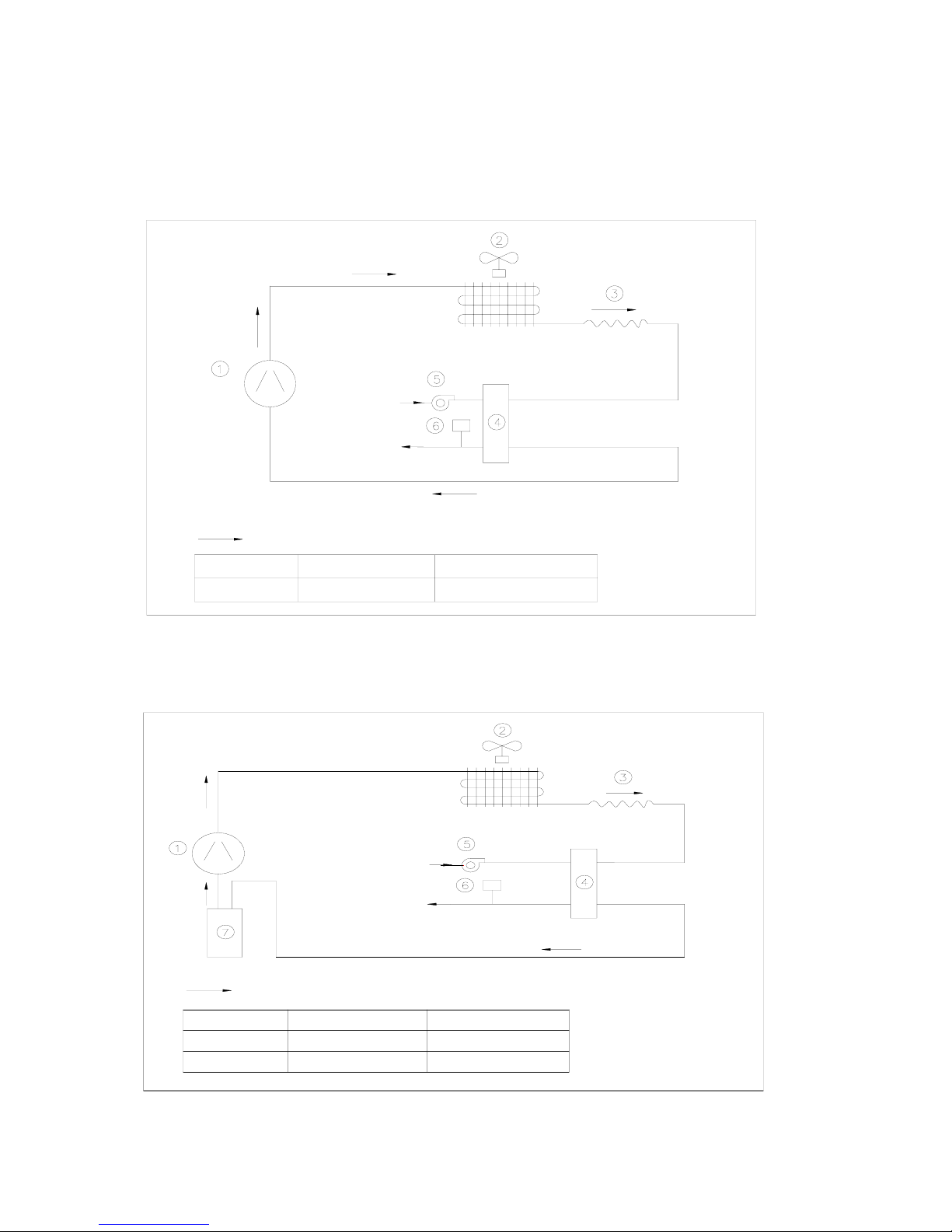
Schematic Diagram
Refrigerant Circuit Diagram
Cooling Only (MAC030C/035C)
Cooling Only (MAC040C/050C/065C/070C)
Ref r i ger ant Fl ow Di r edt i on
5、Wat er Pump
4、BPHE
1、Compr ess or
Chilled Wat er Out
LEGEND
Chilled Wat er I n
2、Heat Exchanger Fan 3、 Cool i ng Cap. Tube
6、Wat er Fl ow Swi t ch
7、Accumul at or
1、Compr essor
4、 BPHE
LEGEND
5、 Wat er Pump
Refrigerant Fow Di rection
Chilled Wat er I n
Chilled Wat er Out
2、 Heat Exchanger Fan 3、 Cool i ng Cap. Tube
6、 Wat er Fl ow Swi t ch
Page 46
Page 47
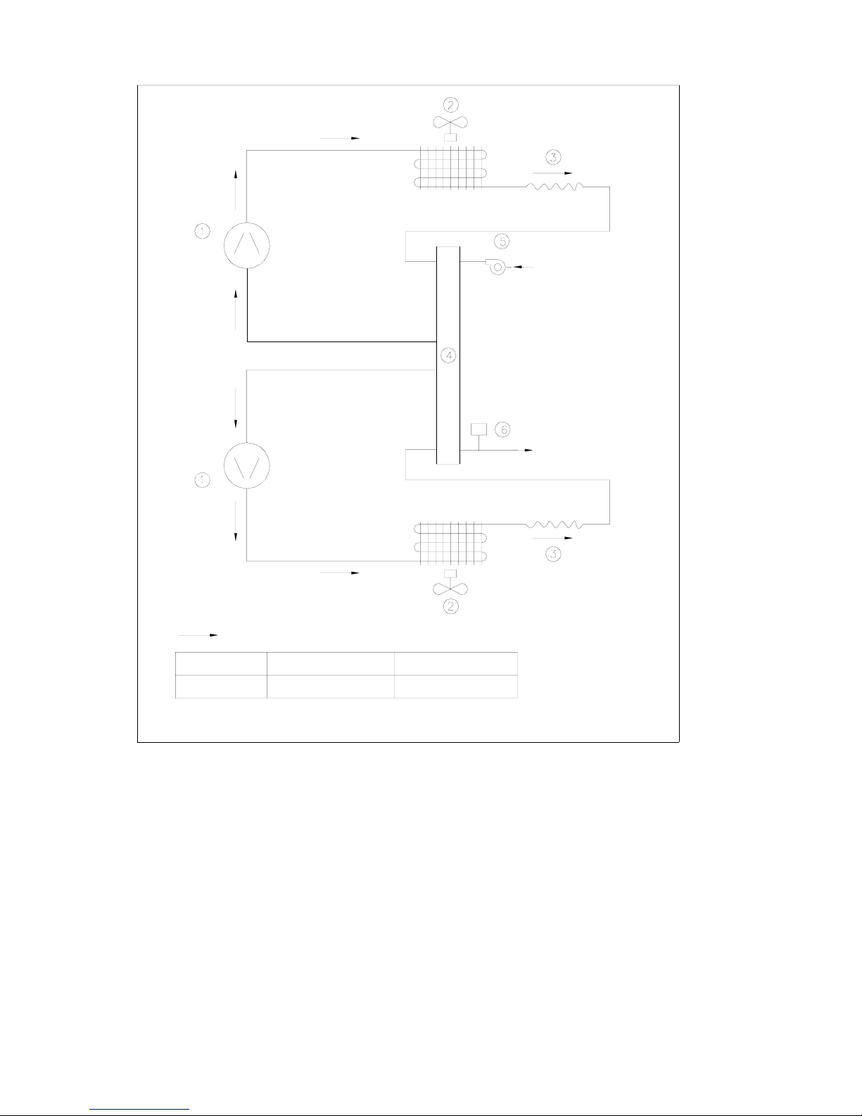
Cooling Only (MAC080C/100C/120C/150C)
Ref r i ger ant Fl ow Di r ect i on
4、BPHE
1、Compr essor
2、Heat Ex changer Fan
5、Wat er Pump
3、Cool i ng Cap. Tube
6、Wat er Fl ow Swi t ch
Chilled Wat er I n
Chilled Wat er Out
LEGEND
Page 47
Page 48

Heat Pump (MAC030CR/035CR)
Heat Pump (MAC040CR/050CR/065CR/070CR)
Heat Exchanger
3、 Copper Tube Al umi ni um Fi n
2、 Four Way Val ve
6、 Heat i ng Cap. Tube
10、 Wat er Fl ow Swi t ch
5、 Cool i ng Cap. Tube
9、 Wat er Pump
1、 Compr essor
LEGEND
7、 Recei ver
Chilled Wat er
Chilled Wat er
Ou t
In
8、 BPHE
Ref r i ger ant Fl ow Di r ect i on When Cool i ng
Ref r i ger ant Fl ow Di r ect i on When Heat i ng
3、 Accumul at or
7、 Heat i ng Cap. Tube
11、Wat er Pump
Chilled Wat er
Chilled Wat er
9、 Recei v er 10、 BPHE
1、 Compr essor
LEGEND
6、 Cool i ng Cap. Tube
2、 Four Way Val ve
Ou t
In
12、 Wat er Fl ow Swi t ch
4、Copper Tube Auminium Fin
Heat Exc hanger
8、 Check Val ve
Refrigerant Flow Directi on When Cool i ng
Refrigerant Flow Directi on When Heat i ng
Page 48
Page 49

Heat Pump (MAC080CR/100CR/120CR/150CR)
Ref r i ger ant Fl ow Di r ect i on When Heat i ng
7、Heat i ng Cap. Tube
11、Wat er Pump
3、Accumul at or
Ref r i ger ant Fl ow Di r ect i on When Cool i ng
1、Compr essor
9、Recei v er
LEGEND
2、Four Way Val v e
6、Cool i ng Cap. Tube
10、BPHE
12、Wat er Fl ow Swi t c h
4、Copper Tube Al uminium Fi n
Heat Exchanger
8、Check Val ve
Chilled Wat er
In
Chilled Wat er
Out
Page 49
Page 50

Parts List and Exploded View
Below is the structure of MAC065CR, units of MAC035C(R) to MAC070C(R) similar to this.
LEGEND:
1.Top panel 2.Horizontal ornament piece 3.Heat exchanger
4.Vertical support(4pcs) 5.Four way valve assy. 6.Side panel
7.Vertical ornament piece 8.Air discharge 9.Air discharge guard
10.Front panel 11.Discharge pipe &pressure switch assy. 12.Compressor
13.Water pump 14.Suction pipe & pressure switch assy. 15.Electrical box
16.PP-R water pipe(1set) 17.Water flow switch 18.Filter drier
19.Base pan assy. 20.Receiver 21.Cap.tube & check valve assy.
22.BPHE 23.Drain pan 24.Accumulator
Page 50
Page 51

Below is the structure of MAC080CR, units of MAC080C(R) to MAC150C(R) similar to this.
Item Name Qty Item Name Qty
1. Fan Guard 2 15. Fan 2
2. Top Panel 2 16. Fan Motor 2
3. Front Panel Support 1 17. Fan Motor Support 2
4. Left & Right Coil Guard 2 18. Rear Coil Guard 2
5. Left Coil Assy. 1 19. Left & Right Vertical Support 2
6. Separate Panel Assy. 1 20. Right Coil Assy. 1
7. Left & Right Side Panel Assy. 2 21. Accumulator 2
8. Front Panel Assy 1 22. BPHE 1
9. Electrical Box Support 2 23. Compressor 2
10. Electrical Box Assy. 1 24. Pump to BPHE Pipe Assy. 1
11. Water Out Pipe Assy. 1 25. Receiver 2
12. Water In Pipe Assy. 1 26. Water Pump 1
13. Left Service Panel Assy. 1 27. Base Pan Assy. 1
14. Right Service Panel Assy. 1
Page 51
Page 52

©2003 McQuay International +1 (800) 432-1342 www.mcquay.com
ISO 9002
REGISTERED
S&E
 Loading...