

Page 1

MWM - G - 2009
Wall Mounted Split Systems
Models:
MWM007G/GR
MWM009G/GR
MWM010G/GR
MWM015G/GR
MWM020G/GR
MWM025G/GR
MWM301/301R
M5WM007G/GR
M5WM009G/GR
M5WM010G/GR
M5WM015G/GR
M5WM020G/GR
M5WM025G/GR
M5WM311/301R
Catalog
Catalog
MWM - G - 2007
Wall Mounted Split Systems
Catalog
MWM - G2 - 2010
Models: MWM 07G2 M5WM 07G2/G2R
MWM 09G2/G2R M5WM 09G2/G2R
MWM 10G2/G2R M5WM 10G2/G2R
MWM 152G/G2R M5WM 15G2/G2R
MWM 20G2/G2R M5WM 20G2/G2R
MWM 25G2/G2R M5WM 25G2/G2R
MWM 030F/FR M5WM 031F/030FR
Page 2

MWM-G2-2010 Table of Contents
Contents
Nomenclature......................................................................................................................1
Indoor Unit .....................................................................................................................1
Outdoor Unit ..................................................................................................................2
Product Line-Up ..................................................................................................................3
Features...............................................................................................................................9
Application Information ...................................................................................................10
Operating Range .........................................................................................................10
Refrigerant Circuit Diagram .........................................................................................11
Controller ....................................................................................................................19
Installation Guideline ...................................................................................................20
Sound Data ........................................................................................................................34
Sound Pressure Level .................................................................................................34
NC Curve .....................................................................................................................35
Engineering & Physical Data ........................................................................................... 38
General Data ...............................................................................................................38
Components Data ........................................................................................................55
Performance Data ............................................................................................................. 72
Calculation Steps .........................................................................................................72
Performance Data .......................................................................................................78
Outline and Dimension ..................................................................................................133
Electrical Data ................................................................................................................. 138
Wiring Diagram ...............................................................................................................146
Service and Maintenance...............................................................................................159
Troubleshooting .............................................................................................................161
Exploded View and Part List .........................................................................................171
“McQuay” is a registered trademark of McQuay International. All rights reserved.
© 2010 McQuay International. All rights reserved throughout the world.
Bulletin illustrations cover the general appearance of McQuay International products at the time of publication.
We reserve the right to change design and construction specifi cations at any time without notice.
2
Page 3

Nomenclature MWM-G2-2010
Nomenclature
Indoor Unit
M WM 10 G2 R
Brand
M
Refrigerant
“ “
4
5
Model Name
WM : Wall Mounted
: McQuay
: Omitted if R22
: R407C
: R410A
Capacity Index
10
20
Chassis
G2
Model Type
“ “
R
: 10,000 Btu/h
: 20,000 Btu/h
: G + Series
: Omitted if cooling only
: Heatpump
1
Page 4

MWM-G2-2010 Nomenclature
Outdoor Unit
M 5 LC 010 C R
Brand
M
Refrigerant
“ “
4
5
Model Name
LC : Single Split Condensing Unit
Capacity Index
010
020
: McQuay
: Omitted if R22
: R407C
: R410A
: 10,000 Btu/h
: 20,000 Btu/h
Chassis
C
Model Type
“ “
R
: C Series
: Omitted if cooling only
: Heatpump
2
Page 5

Product Line-Up MWM-G2-2010
Product Line-Up
Indoor Unit
MWM-G2 Series
Classication
PCB
MWM
Nomenclature
L2.0
07G2 ACICE X X X X X X X
09G2 ACICE X X X X X X X
10G2 ACICE X X X X X X X
15G2 ACICE X X X X X X X
20G2 ACICE X X X X X X X
COOLING
25G2 ACICE X X X X X X X
030F AFBF X X X X X X
Handset
G17
Ionizer Filter
Saranet Filter
Air Purication
Negative Ionizer
Nano Technology Air Filteration
C
Grille
CE
Marking
Others
Orice Kit
3
09G2R ACICE X X X X X X X
10G2R ACICE X X X X X X X
15G2R ACICE X X X X X X X
20G2R ACICE X X X X X X X
HEATPUMP
25G2R ACICE X X X X X X X
030FR AFAE X X X X X
Page 6

MWM-G2-2010 Product Line-Up
Indoor Unit
M5WM-G2 Series
Classication
PCB
M5WM
Nomenclature
L2.0
07G2 ACICE X X X X X X X
09G2 ACICE X X X X X X X
10G2 ACICE X X X X X X X
15G2 ACICE X X X X X X X
20G2 ACICE X X X X X X X
COOLING
25G2 ACICE X X X X X X X
031F AFCE X X X X X
Handset
G17
Filter
Ionizer
Saranet Filter
Air Purication
Negative Ionizer
Nano Technology Air Filteration
C
Grille
Marking
CE
Others
07G2R ACICE X X X X X X X
09G2R ACICE X X X X X X X
10G2R ACICE X X X X X X X
15G2R ACICE X X X X X X X
20G2R ACICE X X X X X X X
HEATPUMP
25G2R ACICE X X X X X X X
030FR AFCE X X X X X
4
Page 7

Product Line-Up MWM-G2-2010
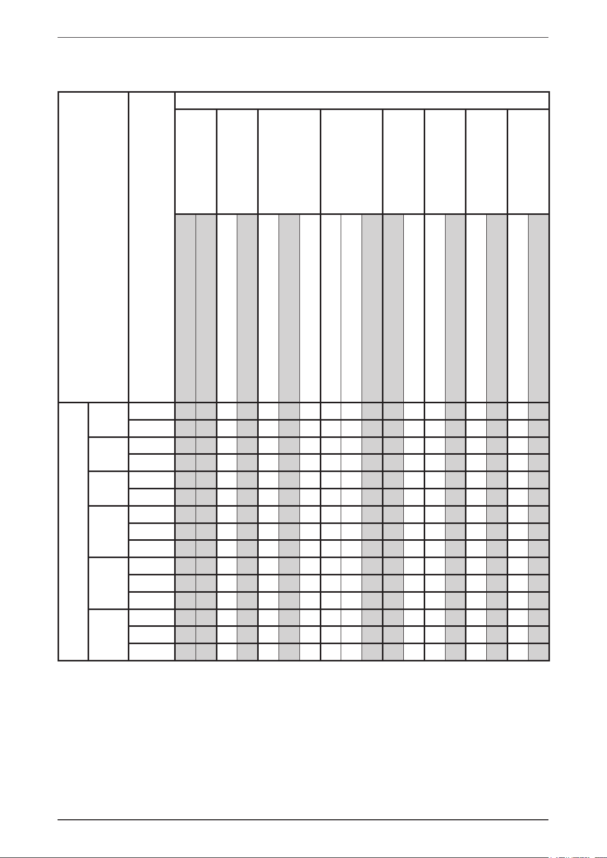
Outdoor Unit
MLC-C Series
Classication
MLC
007C
009C
010C
015C
018C
COOLING
020C
025C
028C
030C
Nomenclature
ACPOE
ACPIE
ACPOD
ACPID
ACPOB
ACPIB
ACPOD
ACPID
ACPOD
ACPID
ACPBD
ACPOD
ACPID
ACPBD
ACPHB
ACPOD
ACPID
ACPBD
ACPHB
ACHOB
ACHIB
ACHBB
AFGE
PCB
Refrigerant Control
Cap Tube
X X X X
X X X X
X X X X
X X X X
X X X X
X X X X
X X X X
X X X X
X X X X
X X X X
X X X X X
X X X X
X X X X
X X X X X
X X X X X X
X X X X
X X X X
X X X X X
X X X X X X
FIN
Gold Coated
X X X
Bare
X X X
X X X X
X X X X X X
Safety Devices
Contactor
High Pressure Switch
Low Pressure Switch
Scroll
Compressor
Rotary
Marking
CE
Others
Back Panel Grille
Special
Super Tropical Specication
5
Page 8

MWM-G2-2010 Product Line-Up
Outdoor Unit
MLC-C Series
Classication
MLC
009CR
010CR
015CR
018CR
020CR
HEATPUMP
025CR
028CR
030CR
Nomenclature
ACPOD
ACPID
ACPOB
ACPIB
ACPOA
ACPIA
ACPOD
ACPID
ACPOD
ACPID
ACPHB
ACPOD
ACPID
ACHIB
ACHOB
ACHIB
AFFB
PCB
Refrigerant Control
Cap Tube
TXV
X X X X
X X X X
X X X X
X X X X
X X X X
X X X X
X X X X
X X X X
X X X X
X X X X
X X X X X
X X X X
X X X X
X X X X X
X X X X
X X X X
X X X X X X X
FIN
Gold Coated
Bare
Safety Devices
Contactor
High Prerssure Switch
Low Pressure Switch
Scroll
Compressor
Rotary
Marking
CE
Others
Drain Elbow
Special
Super Tropical Specication
6
Page 9

Product Line-Up MWM-G2-2010
Outdoor Unit
M5LC-C Series
Classication
M5LC
007C
009C
015C
020C
COOLING
025C
028C
Nomenclature
ACPOE
ACPIE
ACPOB
ACPIB
ACPOC
ACPIC
ACPOC
ACPIC
ACPGC
FCPOC
FCPGC
ACPOC
ACPIC
ACPGC
FCPOC
FCPGC
ACPOA
ACPIA
ACPGA
FCPOA
FCPGA
PCB
Refrigerant Control
Cap Tube
X X X X
X X X X
X X X X
X X X X
X X X X
X X X X
X X X X
X X X X
X X X X X
X X X X X X
X X X X X X X
X X X X
X X X X
X X X X X
X X X X X X
X X X X X X X
X X X X
X X X X
X X X X X
X X X X X X
X X X X X X X
FIN
Gold Coated
Bare
Safety Devices
Contactor
Phase Sequencer
Compressor
Rotary
Marking
CE
Others
Low Ambient Kit
Drain Elbow
Special
7
Page 10
MWM-G2-2010 Product Line-Up
Outdoor Unit
M5LC-C Series
Classication
M5LC
007CR
010CR
015CR
020CR
HEATPUMP
025CR
028CR
Nomenclature
ACPOE
ACPIE
ACPOB
ACPIB
ACPOC
ACPIC
ACPOC
ACPIC
FCPOC
ACPOC
ACPIC
FCPOC
ACPOA
ACPIA
FCPOA
PCB
Refrigerant Control
Cap Tube
X X X X
X X X X
X X X X
X X X X
X X X X
X X X X
X X X X
X X X X
X X X X X X X
X X X X
X X X X
X X X X X X X
X X X X
X X X X
X X X X X X X
FIN
Gold Coated
Bare
Safety Devices
Contactor
Phase Sequencer
Compressor
Rotary
Marking
CE
Others
Low Ambient Kit
Drain Elbow
Special
8
Page 11
Features MWM-G2-2010
Features
Excellent Air Distribution
Air discharge direction can be adjusted in four directions, manually or automatically by using LCD remote
control. The new double louver design with automatic air swing function fully optimizes the room comfort by
distributing the air evenly to the room. The unique skew fan design with larger diameter creates better air ow
to the operating environment.
Self Diagnosis
This function is able to detect and to disgnose any faults occuring in the system by blinking of the LED lights.
Simplify and ease for troubleshooting.
Facilitated Maintenance Ensure
The new design of air discharge housing where by the fan blower can be easily accessed by just losing
two screws on the unit to provides a exible, faster and easier way to clean up the fan blower and ionizer.
Maintenance is easy for electrical components, piping and wiring as these are all easily accessible by merely
removing front plastic panel.
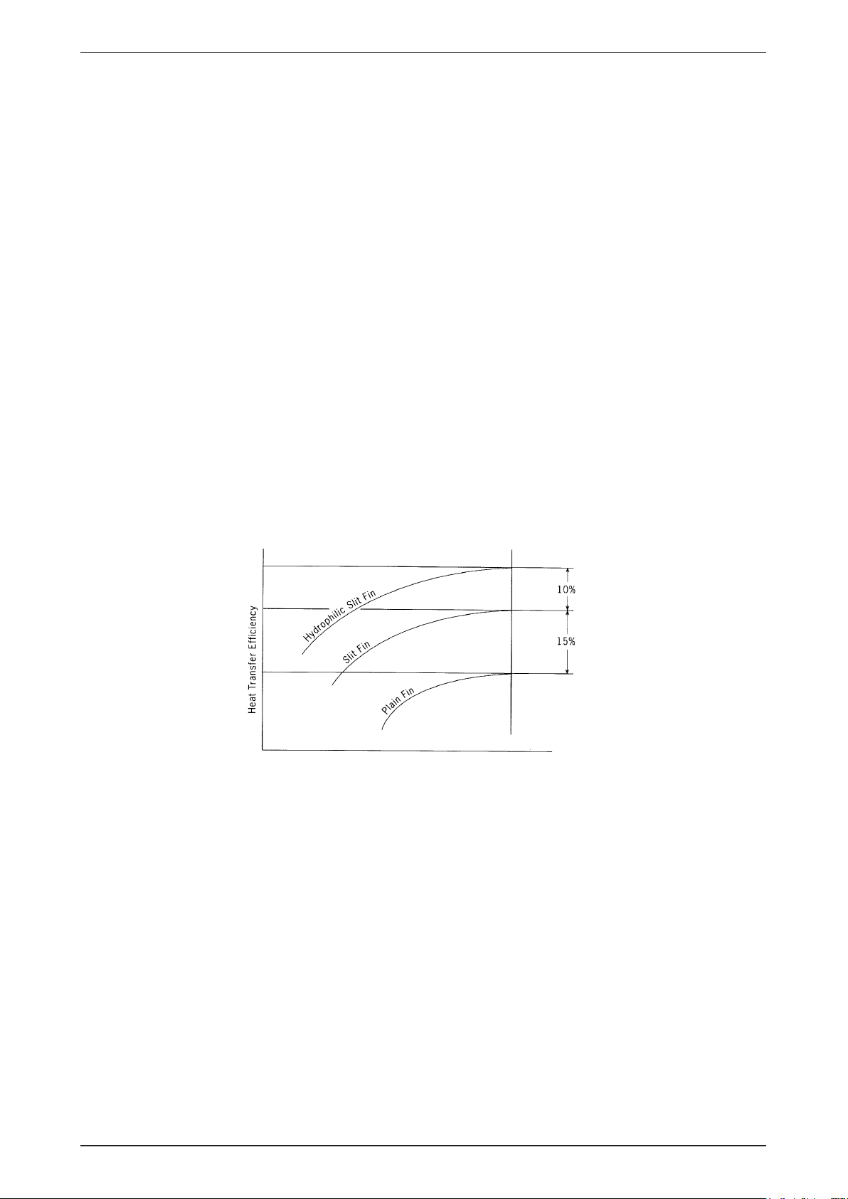
High Efciency Heat Exchanger
The compact design of the 3-fold structure heat exchanger provides a large surface are for better and efcient
heat exchange. The unique Hydrophilic slit n has greatly improved the air ow and the contact surfaces with
the air thus to boost the cooling capacity.
Wireless Remote Controller
The compact LCD transmitter is able to operate the air conditioner unit within the distance of 9 meters.
•
Fan motor speed can be set at low / medium / high or automatic.
•
Sleep mode auto control will gradually increase or decrease the setting temperature to provide a
•
comfortable surrounding for sleeping.
Air ow direction can be controlled automatically.
•
Room temperature is controlled by electronic thermostat.
•
The real time timer allows the air conditioner to be switched on and off automatically based on user
•
settings.
Turbo mode function is available to enables the required set temperature to be achieved in a short time
•
Personalized setting allows user to preset and store 2 groups of personal settings (including timer setting)
•
in the handset.
Auto random restart is a function where by when there is power failure occurred during operation, the unit
•
will automatically restart as the last setting condition once the power is resumed.
Rotary Compressors
The ever popular rotary compressor is more energy efcient and has a higher output to weight ratio.
9
Page 12
MWM-G2-2010 Application Information
Note :
Standard operating range.
With Low ambient kit. (Optional item)
Please refer to local dealer for unit of this specification.
Indoor temp. (°CDB)
Cooling
Outdoor temp. (°CDB)
Indoor temp. (°CWB)
Outdoor temp. (°CDB)
Indoor temp. (°CWB)
Heating
Outdoor temp. (°CWB)
-9
16 21
6
30
-5
19
35
14
46
23
Standard
point
Low ambient kit
18
-5
19
35
14
46
23
Low ambient kit
Standard
point
Standard
point
! Caution :
The use of your air conditioner
outside the range of working
temperature and humidity can
result in serious failure.
Application Information
Operating Range
Ensure the operating temperature is in allowable range.
Cooling only
Heatpump
10
Page 13
Application Information MWM-G2-2010
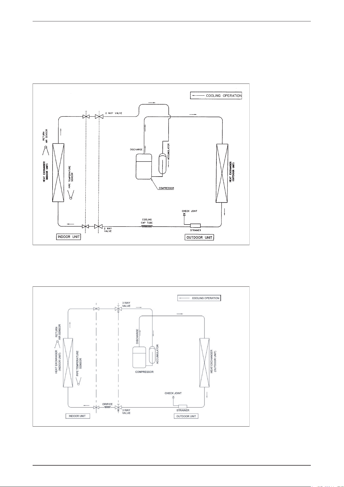
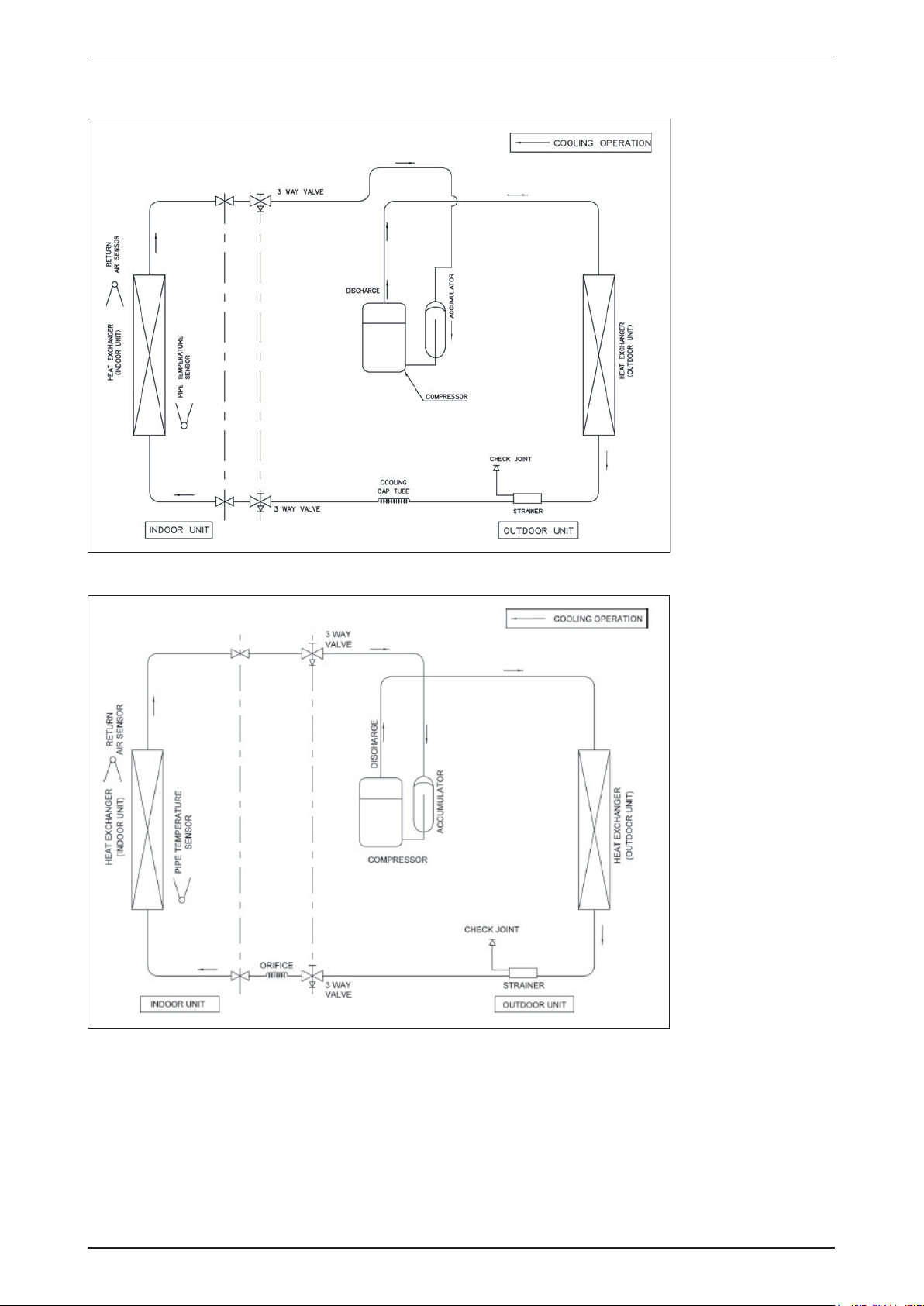
Refrigerant Circuit Diagram
Model: MWM07G2 - MLC007C M5WM07G2 - M5LC007C
MWM09G2 - MLC009C M5WM09G2 - M5LC009C
MWM10G2 - MLC010C M5WM10G2 - M5LC010C
MWM15G2 - MLC015C M5WM15G2 - M5LC015C
Model: MWM20G2 - MLC018C M5WM20G2 - M5LC020C
MWM20G2 - MLC020C M5WM25G2 - M5LC025C
11
Page 14
MWM-G2-2010 Application Information
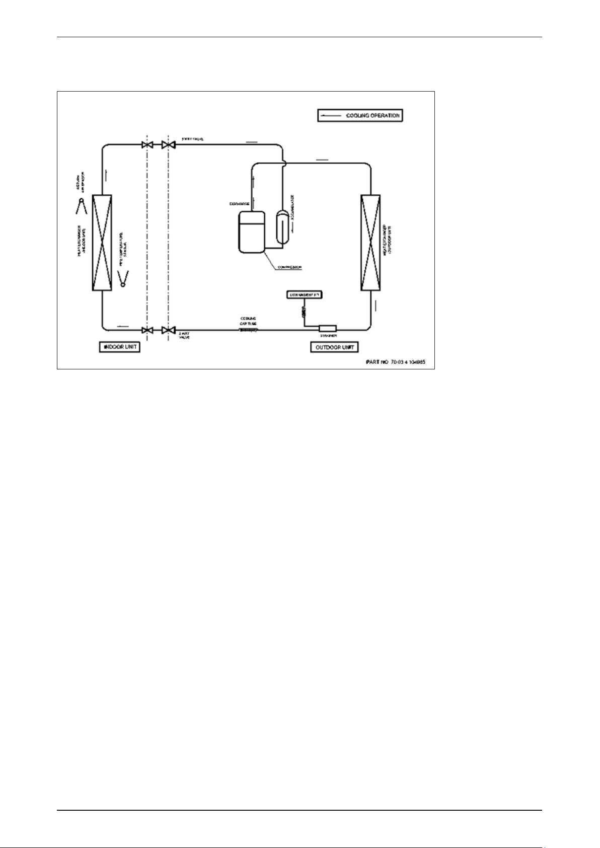
Model: MWM25G2 - MLC025C M5WM031F - M5LC028C
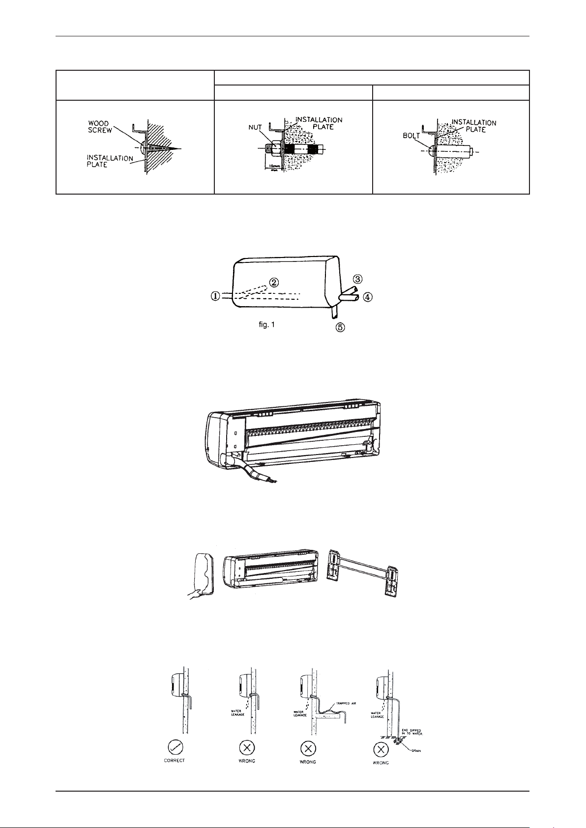
Model: MWM030F - MLC028C
12
Page 15

Application Information MWM-G2-2010
Model: MWM030F – MLC030C
13
Page 16
MWM-G2-2010 Application Information
Model: M5WM20/25G2 - M5LC020/025C (With Low Ambient Kit)
M5WM030F - M5LC028C (With Low Ambient Kit)
14
Page 17

Application Information MWM-G2-2010
Model: MWM09G2R - MLC009CR M5WM07G2R - M5LC007CR
Model: MWM10G2R - MLC010CR M5WM09G2R - M5LC010CR
M5WM10G2R - M5LC010CR
15
Page 18

MWM-G2-2010 Application Information
Model: MWM15G2R - MLC015CR M5WM15G2R - M5LC015CR
Model: MWM20G2R - MLC020CR M5WM20G2R - M5LC020CR
M5WM25G2R - M5LC025CR
16
Page 19

Application Information MWM-G2-2010
Model: MWM030FR - MLC028CR M5WM030FR - M5LC028CR
Model: MWM25G2R - MLC025CR
17
Page 20

MWM-G2-2010 Application Information
Model: MWM030FR – MLC030CR
18
Page 21

Application Information MWM-G2-2010
MODE
P1 P2
SLEEP
SET
CANCEL
ON TIMER
SET
CANCEL
OFF TIMER
6
12
15
11
13
14
7
4
3
10
9
2
1
8
5
Controller
G17
Operation Guide
1 Transmission Source
The source where the signal will be transmitted.•
Signal Transmission Indication
2
Blink to conrm that the last setting has been transmitted
•
to the unit.
Temperature Setting
3
To set the desired room temperature, press the v or V
•
button to increase orde crease the set temperature.
The temperature setting range is from 16°C to 30°C
•
(optional setting 20°C to 30°C).
Personalize Setting
4
Press and hold for 3s, then will blink. Press again to
•
cycle between and
Set the desire setting, then leave the hand set for 4s
•
without pressing any key and it will save the setting into the
programme.
Press once to activate the P1 setting, press again to
•
cycle between P1 and P2.
Press any key to deactivate the personalize setting.
•
5
Automatic Air Swing (optional)
Press the SWING button to activate the automatic air
•
swing function.
To distribute the air to a specic direction, press the
•
SWING button and wait until the louver move to the
desired direction and press the button once again.
Silent Function
6
Press for quiet operation.
•
Fan speed turn to minimum speed.
•
Press again to deactivate the function.
•
Sleep Mode Setting
7
Press the SLEEP button will activate the sleep mode
•
function. This function is available under COOL, HEAT and
AUTO mode.
When the unit is operating under cooling mode, the set
•
temperature is increased by 0.5°C after 30 minutes, 1°C
after an hour, and 2°C after 2 hours.
When the unit is operating under heating mode, the set
•
temperature is decreased by 1°C after 30 minutes, 2°C
after an hour, and 3°C after 2 hours.
19
8 Operating Mode
Press the MODE button to select the type of operating
•
mode.
For cooling only unit, the available modes are: COOL (),
•
DRY () and FAN ( ).
9
Fan Speed Selection
Press the button continuously will toggle the fan speed
•
in the following order:
Low p Med p High p Auto
Stop pressing when the desired fan speed appears on the
•
display screen.
10
“ON/OFF” Button
Press one to start the air conditioner unit.
•
Press again to stop the unit.
•
11
Timer Cancel
Press the TIMER CANCEL button to cancel the on timer
•
setting.
12
OFF Timer Setting
Press the OFF TIMER button will activate the off timer
•
function.
Set the desired off time by pressing the OFF TIMER button
•
continuously.
13
ON Timer Setting
Press the ON TIMER button will activate the on timer
•
function.
Set the desired on time by pressing the ON TIMER
•
button continuously. If the timer is set to 7.30am, the air
conditioner will turn on at 7.30am sharp.
14
Turbo Function
Press for fast cooling.
•
Fan speed turn to maximum speed.
•
Press again to deactivate the function.
•
Clock Time Setting
15
Press and hold to set the clock time.•
Page 22

MWM-G2-2010 Application Information
Installation Guideline
Safety Precautions
WARNING
•
Installation and maintenance should be performed by
qualified persons who are familiar with local code and
regulation, and experienced with this type of appliance.
•
All field wiring must be installed in accordance with the
national wiring regulation.
•
Ensure that the rated voltage of the unit corresponds
to that of the name plate before commencing wiring
work according to the wiring diagram.
•
The unit must be GROUNDED to prevent possible
hazard due to insulation failure.
•
All electrical wiring must not touch the refrigerant
piping or any moving parts of the fan motors.
•
Confirm that the unit has been switched OFF before
installing or servicing the unit.
•
Disconnect from the main power supply before
servicing the air conditioner unit.
•
DO NOT pull out the power cord when the power is
ON. This may cause serious electrical shocks which
may result in fire hazards.
•
Keep the indoor and outdoor units, power cable and
transmission wiring, at least 1m from TVs and radios,
to prevent distorted pictures and static. {Depending on
the type and source of the electrical waves, static may
be heard even when more than 1m away}.
CAUTION
Please take note of the following important points
when installing.
Do not install the unit where leakage of ammable
•
gas may occur.
If gas leaks and accumulates around the unit, it
may cause re ignition.
Ensure that drainage piping is connected properly.
•
If the drainage piping is not connected properly,
it may cause water leakage which will dampen
the furniture.
Do not overcharge the unit.
•
This unit is factory pre-charged. Overcharge will
cause over-current or damage to the compressor.
Ensure that the unit’s panel is closed after service
•
or installation.
Unsecured panels will cause the unit to operate
noisily.
Sharp edges and coil surfaces are potential
•
locations which may cause injury hazards. Avoid
from being in contact with these places.
Before turning off the power supply, set the remote
•
controller’s ON/OFF switch to the “OFF” position
to prevent the nuisance tripping of the unit. If this is
not done, the unit’s fans will start turning automatically
when power resumes, posing a hazard to service
personnel or the user.
Do not operate any heating apparatus too close to the
•
air conditioner unit. This may cause the plastic panel to
melt or deform as a result of the excessive heat.
Ensure the color of wires of the outdoor unit and
•
the terminal markings are same to the indoors
respectively.
IMPORTANT
•
AIR CONDITIONER UNIT IN A LAUNDRY ROOM.
•
Do not use joined and twisted wires for incoming
•
power supply.
: DO NOT INSTALL OR USE THE
NOTICE
Disposal requirements
Your air conditioning product is marked with this symbol. This means that electrical and electronic products
shall not be mixed with unsorted household waste.
Do not try to dismantle the system yourself: the dismantling of the air conditioning system, treatment of
the refrigerant, of oil and of other parts must be done by a qualied installer in accordance with relevant
local and national legislation. Air conditioners must be treated at a specialized treatment facility for re-use,
recycling and recovery. By ensuring this product is disposed of correctly, you will help to prevent potential
negative consequences for the environment and human health. Please contact the installer or local authority
for more information.
Batteries must be removed from the remote controller and disposed of separately in accordance with relevant
local and national legislation.
20
Page 23

Application Information MWM-G2-2010
Indoor Unit
Outdoor Unit
Refrigerant Piping
Air Discharge
Nozzle
Air Intake
Drain Hose
Signal Receiver
Indicator Light
Air Intake
Grille
Back Housing
ON/OFF Switch
Front Frame
Air Filter
Installation Diagram
Before installing the unit, ensure that the power supply matches the power requirement of the airconditioner.•
Caution
21
Page 24

MWM-G2-2010 Application Information
Maintenance &
Servicing Space
Air Flow
Direction
50.0 mm
50.0 mm
mm0.05
Higher Than
Eye Level
Selection of Location and Space
Indoor Unit
Install the fan coil (indoor) unit at a location with the following requirements
Location is suitable for wiring, piping and drainage.
•
No obstruction of air ow into and out of unit where cooler air can be evenly distributed.(See g. 1)
•
Ensure that air discharge is not short circuited with air intake.
•
Ensure that wall is sufciently strong, rigid, at, perpendicular and vibration free.
•
Where air lter cassette can be slided in or out easily.
•
Where there is no danger of ammable gases.
•
Where there is no direct sunlight on unit.
•
Also to take into consideration a place for the installation of the Wireless LCD Remote Controller.
•
Do not install unit near the door waybecause excessive fresh air may causepanel condensation on the unit.•
Caution
22
Page 25

Application Information MWM-G2-2010
Outdoor Unit
As condensing temperature rises, evaporating temperature rises and cooling capacity drops. In order to achieve
maximum cooling capacity, the location selected for outdoor unit should fulll the following requirements :
Install the condensing (outdoor) unit in a way such that hot air distributed by the outdoor condensing unit
•
cannot bedrawn in again (as in the case of short circuit of hot discharge air). Allow sufcient space for
maintenance around the unit.
•
Ensure that there is no obstruction of air ow into or out of the unit. Remove obstacles which block air
intake ordischarge.
•
The location must be well ventilated, so that the unit can draw in and distribute plenty of air thus lowering
the condensing temperature.
•
A place capable of bearing the weight of the outdoor unit and isolating noise and vibration.
•
A place protected from direct sunlight. Otherwise use an awning for protection, if necessary.
•
The location must not be susceptible to dust or oil mist.
Installation Clearance
•
Outdoor units must be installed such that there is no short circuit of the hot discharge air or obstruction to
smooth airow. Select the coolest possible place where intake air should not be hotter than the outside
temperature (max. 45°C)
ALL MODELS A B C D
Minimum Distance 300 mm 1000 mm 300 mm 500 mm
CAUTION : If the condensing unit is operated in an atmosphere containing oils (including machine oils), salt (coastal area),
sulphide gas (near hot spring, oil renery plant), such substances may lead to failure of the unit.
Caution
If the condensing unit is operated in an atmosphere containing oils(including machine oils),salt(coastal area), sulphide
•
gas(near hot spring, oil renery plant), such substances may lead to failure of theunit.
23
Page 26

MWM-G2-2010 Application Information
A
Installation of Outdoor Unit
Condensed Water Disposal of Outdoor Unit (Heat Pump Unit Only)
There are 2 holes on the base of outdoor unit for condensed water to ow out. Insert the drain elbow toone
•
of the holes.
To install the drain elbow, rst insert one portion of the hook to the base (portion A), then pull the
•
drainelbow in the direction shown by the arrow while inserting the other portion to the base. After
installation,check to ensure that the drain elbow clings to base rmly.
If the unit is installed in a snowy and chilly area, condensed water may freeze in the base. In such case,
•
please remove plug at the bottom of unit to smooth the drainage.
24
Page 27

Application Information MWM-G2-2010
Drilling Holes and Mounting Installation Installation Plate
Caution
Please check the unit weight for each model. Always ensure that the wall is sufciently strong to withstandthe weight. If
•
not, it is necessary to reinforce the wall with plate, beams or pillars.
The unit cannot be directly xed onto the wall or the likes. In all cases, the installation plate provided MUST be used.
•
Paste the installation plan provided on the desired location on the wall and mark the holes location
•
accordingly.
Ensure that the minimum maintenance and servicing space at the top, left and right side of the unit
•
isreserved.
Ensure also the levelness of the installation plate.
•
Drill the screw mounting holes (minimum 4 screws are required).
•
Drill the pipe hole at the location as per plan. (This is only applicable for rear piping outlet installation).
•
Note: The hole should be drilled slightly lower at outdoor side as per gure below:--
Fix the installation plate rmly to wall, without tilting to left or right. Use a plumb line, if available.
•
Model DIMENSION “A”
MWM07/09G2/G2R
M5WM07/09G2/G2R
MWM10/15G2/G2R
M5WM10/15G2/G2R
350.0 mm
400.0 mm
MODEL
MWM20/25G2/G2R, M5WM20/25G2/G2R, MWM030F/030FR, M5WM031F/030FR
25
Page 28
MWM-G2-2010 Application Information
Fixing method:-
•
WOODENFRAME WALL
REINFORCED CONCRETE BUILDING
NUT ANCHOR BOLT ANCHOR
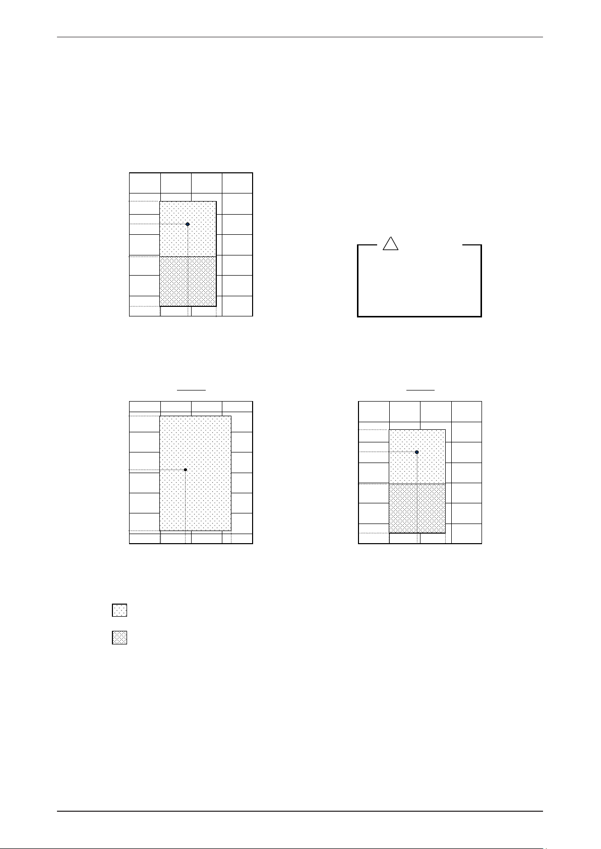
Indoor Unit Preparation
•
The refrigerant piping can be routed to the unit in 5 direction, by using the cut outs in the unit casing.
(See g. 1)
Carefully bend the pipes to the required position to align with the hole. For right hand and rear side
•
drawout, hold the bottom of the piping and x direction before shaping it to the desired position
(See g. 2). The condensation drain hose should be taped to the pipes with vinyl tape. The electrical cable
can also betaped to the pipes.
Mounting Indoor Unit
Hook the indoor unit onto the upper portion of installation plate. (Engage the 2 hooks of rear top of the indoor
unit withthe upper edge of the installation plate). Ensure the hooks are properly seated on the installation plate
by moving in left and right.
Water Drainage Piping
The indoor drain pipe must be downward gradient for smooth drainage. Avoid situation as shown in gure
below.
26
Page 29

Application Information MWM-G2-2010
Wiring
Electrical Connection
Wiring regulation on wire diameters differ from country to country. Please refer to your LOCAL
•
ELECTRICAL CODES for eld wiring rules. Be sure that installation comply with such rules and
regulations.
General Precautions
Ensure that the rated voltage of the unit corresponds to the name plate before carrying out proper wiring
•
according to the wiring diagram.
Provide a power outlet to be used exclusively for each unit. A power supply disconnect and a circuit
•
breaker for over current protection should be provided in the exclusive line.
The unit must be GROUNDED to prevent possible hazards due to insulation failures.
•
All wiring must be rmly connected.
•
All wiring must not touch the hot refrigerant piping, compressor or any moving parts of fan motors.
•
The eld wires from the indoor unit must be clamped on the wire clamp as per shown in the gure.
•
Refrigerant Piping
Maximum pipe Length and Maximum Number of Bends
Always choose the shortest path for refrigerant piping and follow the recommendations as tabulated below:
Model
Data
Max. Length, L (m) 12 12 12 12 15 15 15
Max. Elevation, H (m) 5 5 5 5 8 8 8
Max. No. of Bends 10 10 10 10 10 10 10
Flare Connection
Cut the pipe stages by stages, advancing the blade of pipe cutter slowly.
•
Remove burr with the burr remover. Hold the aring end down to prevent burrs from dropping inside pipe.
•
MWM/
M5WM
07G2/G2R
MWM
09G2/G2R
MWM/
M5WM
10G2/G2R
MWM/
M5WM
15G2/G2R
MWM/
M5WM
20G2/G2R
MWM/
M5WM
25G2/G2R
M5WM
031F/030FR
MWM030F/
R
27
Page 30

MWM-G2-2010 Application Information
Orifice Pipe
Liquid Pipe
The exact length of pipe protruding from the face of the are die is determined by the aring tool. The table
•
shows the use of an imperial die and riged die.
A(mm)
PIPE Ø, D (mm)
IMPERIAL DIE RIGED DIE
6.35 (1/4”) 1.3 0.7
9.52 (3/8”) 1.6 1
12.7 (1/2”) 1.9 1.3
15.88 (5/8”) 2.2 1.7
Fix the pipe rmly on the are die. Match the centers of both the are die and the aring punch, and tighten
aring punch fully.
INSTALLATION OF SEPARATE ORIFICE KIT AT OUTDOOR
i) Outdoor Unit Installation Space Is Wide Enough
Directly connect the “Female” nut of orice pipe to
•
the liquid pipe.
Flare the liquid pipe and connect it to the “Male”
•
joint of the orice pipe.
28
Page 31

Application Information MWM-G2-2010
Step 4
Step 3
Step 2
Step 1
Orifice Pipe
Liquid Pipe
Brazer
Liquid Pipe
Orifice Pipe
Liquid Pipe
Orifice Pipe
ii) Outdoor Installation Space Is Limited
If the orice pipe can not be connected directly to
•
the liquid valve due tolimitation space, it can be
connected between the liquid pipes.
Flare the liquid pipe and connect it to the liquid
•
valve.
Braze an addition “Male” joint to the liquid pipe.•
Connect the “Female” nut of the orice pipe to the
•
“Male” joint.
Flare another liquid pipe and connect it to the
•
“Male” joint of the orice pipe.
29
Page 32

MWM-G2-2010 Application Information
VACUUMING AND CHARGING
The precharged outdoor unit does not need any vacuuming or charging. However once it is connected, the
•
connecting pipe line and the indoor need to be vacuumed before releasing the R22/R407C/R410A from
the outdoor unit.
1) Open the service port core cap.
2) Connect pressure gauge to the service port.
3) Connect the line to vacuum pump. Open the charging manifold valve and turn the pump on. Vacuum
to–0.1 MPa (-760mmHg) or lower. (Evacuation time varies by the pump but averagely in 1 hour).
Note : R407C – Fix lter dryer
R22 - Nil
R410A - Nil
4) After evacuation, unscrew the spindle (diagram B) for the gas to run to indoor unit.
30
Page 33

Application Information MWM-G2-2010
4) Decision by low side pressure. Turn compressor on for 10 or 15 min.
Model
MWM07 G2 5.
09 G2
MWM
MWM10 G2 4.9 ~ 5.7 70.6 ~ 81.8 5.4 ~ 6.1 76.5 ~ 86.6
MWM15 G2 4.7 ~ 5.2 67.6 ~ 74.7 5.2 ~ 5.6 74.0 ~ 80.4
MWM20 G2
MWM25 G2 37~761.5~7.476~957.4~1.4
MWM030F 4.0 ~ 4.8 56.9 ~ 68.3 4.5 ~ 5.0 64.0 ~ 71.1
MWM07G 2R
MWM09G 2R 4.8 ~ 5.7 68.9 ~ 81.4 5.2 ~ 5.9 73.7 ~ 84.8
MWM10G 2R 4.9 ~ 5.9 70.5 ~ 83.7 5.4 ~ 6.3 76.5 ~ 90.7
MWM15G 2R
MWM20G 2R 77~074.5~9.427~660.5~6.4
MWM25G 2R
MWM030FR 4.0 ~ 4.8 56.9 ~ 68.3 4.5 ~ 5.0 64.0 ~ 71.1
2 ~ 5.7 74.3 ~ 81.0 5.7 ~ 6.2 81.9 ~ 89.1
4.7 ~ 5.5 66.6 ~ 78.6 5.0 ~ 5.8 71.2 ~ 83.1
5.2 ~ 5.8 74.8 ~ 82.3 5.6 ~ 6.1 79.3 ~ 87.7
4.9 ~ 6.3 69.4 ~ 89.3 5.0 ~ 6.6 71.7 ~ 93.8
noitidnoCdaoLyvaeHnoitidnoCdradnatS
C°34roodtuO/C°23roodnIC°53roodtuO/C°72roodnI
gisp²mc/gkgisp²mc/gk
47~072.5~9.496~668.4~6.4
37~761.5~7.486~068.4~2.4
M5WM07 G2
M5WM0 9G2/10 G2 9.4 ~ 9.9 134.9 ~ 141.8 10.2 ~ 10.6 145.4 ~ 152.1
M5WM15 G2 8.9 ~ 9.3 127.3 ~ 132.3 9.3 ~ 9.7 133.1 ~ 138.1
M5WM20 G2
M5WM25 G 8.0 ~ 8.3 114 ~ 118 9.0 ~ 9.2 128 ~ 132
M5WM031F 8.0 ~ 8.6 114 ~ 122 8.7 ~ 9.4 124 ~ 133m
M5W M07G 2R
M5WM09G 2R/10 G2R 9.4 ~ 9.9 134.4 ~ 141.9 9.9 ~ 10.5 141.4 ~ 149.7
M5WM15G 2R 9.0 ~ 9.4 128.0 ~ 134.2 9.4 ~ 9.9 134.6 ~ 142.0
M5WM20G 2R
M5WM25G 2R 7.7 ~ 8.3 110 ~ 118 8.4 ~ 9.0 120 ~ 129
M5WM030FR
9.6 ~ 10.0 137.5 ~ 143.2 10.4 ~ 10.7 148.4 ~ 153.1
8.5 ~ 8.8 121 ~ 125 9.3 ~ 9.6 133 ~ 137
9.6 ~ 9.9 136.6 ~ 141.0 10.8 ~ 11.1 154.1 ~ 159.1
8.3 ~ 8.8 119 ~ 125 8.8 ~ 9.2 125 ~ 132
8.0 ~ 8.6 114 ~ 122 8.7 ~ 9.4 124 ~ 133
Within the value refrigerant cycle normal.
Lower than value refrigerant cycle has some leaks check, amend and top up is necessary. Extremely low
(@ zero) needs evacuation and charge.
Additional Charge
The refrigerant gas is charged in the outdoor unit and, if the piping length is 7.6m, additional charge of
•
there frigerant after vacuuming is not necessary.
When the piping length is more than 7.6m, please use the table below :
•
Additional charge in gram.
10m 12m 15m 25m 35m
R22 MODELS
MWM07G2 / 09G2 / 10G2 / 15G2
MWM20G2
MWM25G2
MWM030F
MWM07G2R / 09G2R / 10G2R / 15G2R
MWM20G2R
MWM25G2R
MWM030FR
R410A MODELS
M5WM07G2 / 09G2 / 10G2 / 15G2
M5WM20G2
M5WM25G2
M5WM031F
M5WM07G2R / 09G2R / 10G2R / 15G2R
M5WM20G2R
M5WM25G2R
M5WM030FR
35 65 - - -
35 65 110 - -
90 165 280 - -
90 165 280 650 1030
50 90 - - -
60 110 185 - -
120 220 370 - -
120 220 370 870 1370
35 60 - - -
35 60 100 - -
80 150 255 - -
80 150 255 600 950
45 80 - - -
55 100 165 - -
110 200 335 - -
110 200 335 790 1250
31
Page 34

MWM-G2-2010 Application Information
Diagram shows typical charging method.
Caution For R410A
Avoid prolong exposure of an opened compressor, or the internal part of refrigerant piping to moist air. The POE oil in
•
the compressor and piping can absorb moisture from air.
Final Checking
Ensure that steps 1 to 8 are closely followed.
•
Ensure the following, in particular :
•
1) The unit is mounted solidly and rigidly in position.
2) Piping and connections are leak proof after charging.
3) Proper wiring has been done.
Trial run
•
1) Conduct a trial run after water drainage test and gas leakage test.
2) Watch out for the following :-
a) Is the electric plug rmly inserted into the socket?
b) Is there any abnormal sound from unit?
c) Is there any abnormal vibrations with regard to unit itself or pipings?
d) Is there smooth drainage of water?
Check that :
•
1) Condenser fan is running, with warm air blowing off the condensing unit.
2) Evaporator blower is running and discharging cool air.
3) Suction (Low side) pressure as per recommended.
4) The remote controller incorporate a 3 minute delay in their circuit. Thus, it requires about 3 minutes
uponcut off before the outdoor condensing unit can start up.
SPECIAL PRECAUTIONS WHEN DEALING WITH REFRIGERANT R410A UNIT
1) WHAT IS NEW REFRIGERANT R410A?
R410A is a new HFC refrigerant which does not damage the ozone layer. The working pressure of this
new refrigerant is 1.6 times higher than conventional refrigerant (R22), thus proper installation / servicing
is essential.
2) COMPONENTS
Mixture weight composition R32(50%) and R125(50%)
32
Page 35

Application Information MWM-G2-2010
Dip-pipe
Liquid
withdrawal
Invert cylinder
without dip-pipe
3) CHARACTERISTIC
•
R410A liquid and vapor components have different compositions when the uid evaporates or
condenses. Hence, when leak occurs and only vapor leaks out, the composition of the refrigerant
mixture left in the system will change and subsequently affect the system performance. DO NOT add
new refrigerant to leaked system. It is recommended that the system should be evacuated thoroughly
before recharging withR410A.
•
When refrigerant R410A is used, the composition will differ depending on whether it is in gaseous or
liquid phase. Hence when charging R410A, ensure that only liquid is being with drawn from the cylinder
or can.This is to make certain that only original composition of R410A is being charged into the system.
•
POE oil is used as lubricant for R410A compressor, which is different from the mineral oil used for R22
compressor. Extra precaution must be taken not to expose the R410A system too long to moist air.
4) CHECK LIST BEFORE INSTALLATION/SERVICING
•
Tubing
Refrigerant R410A is more easily affected by dust of moisture compared with R22, make sure to
temporarily cover the ends of the tubing prior to installation
•
Compressor oil
No additional charge of compressor oil is permitted.
•
Refrigerant
No other refrigerant other that R410A
•
Tools (size of service port is different from R22 system)
Tools specically for R410A only (must not be used for R22 or other refrigerant)
i) Manifold gauge and charging hose
ii) Gas leak detector
iii) Refrigerant cylinder/charging cylinder
iv) Vacuum pump c/w adapter
v) Flare tools
vi) Refrigerant recovery machine
5) HANDLING AND INSTALLATION GUIDELINES
Like R22 system, the handling and installation of R410A system are closely similar. All precautionary
measures;such as ensuring no moisture, no dirt or chips in the system, clean brazing using nitrogen, and
thorough leakcheck and vacuuming are equally important requirements. However, due to its hydroscopic
POE oil, additional precautions must be taken to ensure optimum and trouble free system operation.
a) During installation or servicing, avoid prolong exposure of the internal part of the refrigerant system tomoist
air. Residual POE oil in the piping and components can absorb moisture from the air.
b) Ensure that the compressor is not expose to open air for more than the recommended time specied byits
manufacturer (typically less than 10 minutes). Removed the seal plugs only when the compressor is about
to be brazed.
c) The system should be thoroughly vacuumed to 1.0 Pa ( 700mmHg) or lower. This vacuuming level is more
stringent than R22 system so as to ensure no incompressible gas and moisture in the system.
d) When charging R410A, ensure that only liquid is being with drawn from the cylinder or can. This is to ensure
that only the original composition of R410A is being delivered into the system. The liquid composition can
be different from the vapor composition.
f) Normally, the R410A cylinder or can is being equipped with a dip pipe for liquid with drawal. However,
if thedip pipe is not available, invert the cylinder or can so as to with draw liquid from the valve at the
bottom.
33
Page 36

MWM-G2-2010 Sound Data
Sound Data
Sound Pressure Level
Model
MWM07G2
MWM09G2/G2R
M5WM07G2/G2R
M5WM09G2/G2R
MWM10G2/G2R
M5WM10G2/G2R
MWM15G2/G2R
M5WM15G2/G2R
MWM20G2/G2R
M5WM20G2/G2R
MWM25G2/G2R
M5WM25G2/G2R
Speed
(RPM)
High 32 34 38 37 32 23 15 40 36
Medium 27 30 34 32 26 17 14 35 31
Low 24 27 29 26 20 13 13 29 24
High 28 34 37 36 31 22 13 39 35
Medium 27 30 33 31 25 17 12 34 30
Low 24 26 28 25 19 12 11 28 23
High 30 35 39 38 33 25 15 42 37
Medium 28 31 34 33 26 18 13 36 32
Low 24 26 28 26 20 13 12 29 24
High 37 44 42 37 34 25 15 43 37
Medium 34 40 39 34 30 21 14 40 34
Low 30 35 35 30 26 18 13 35 30
High 41 48 47 43 40 32 23 49 43
Medium 39 44 43 39 35 28 20 44 38
Low 37 41 40 36 32 25 19 42 35
1/1 Octave Sound Pressure Level (dB, ref 20µPa)
125 Hz 250 Hz 500 Hz 1k Hz 2k Hz 4k Hz 8k Hz
Overall
(dBA)
Noise
Criteria
High 42 46 45 44 41 35 28 49 43
MWM030F/030FR
M5WM031F/030FR
Microphone position - M5WM/MWM-G/GR : 1m in front and 0.8m below the vertical centre line of the unit. (JIS C 9612)
- M5WM/MWM030F/FR : 1m in front and 1m below the vertical centre line of the unit. (JIS B 8615)
MWM07G2 MWM20G2/G2R
MWM09G2/G2R MWM25G2/G2R
MWM10G2/G2R
MWM15G2/G2R
M5WM07G2/G2R M5WM20G2/G2R
M5WM09G2/G2R M5WM25G2/G2R
M5WM10G2/G2R
M5WM15G2/G2R
M5WM030F/030FR
M5WM031F/030FR
Medium 40 45 44 43 35 33 27 47 42
Low 37 43 43 40 35 30 26 45 39
Model Measuring location
Standard : JIS C 9612
Standard : JIS B 8615
34
Page 37

Sound Data MWM-G2-2010
125 250 500 1000 2000 4000 8000
Octave-band frequency (Hz)
125 250 500 1000 2000 4000 8000
Octave-band frequency (Hz)
MWM07/09G2/G2R , M5WM07/09G2/G2R
NC CURVES
60
50
NC-45
40
30
20
Sound pressure level (dB,ref 20µPa)
10
0
60
High Fan
Medium Fan
Low Fan
MWM10G2/G2R , M5WM10G2/G2R
NC CURVES
NC-40
NC-35
NC-30
NC-25
NC-20
50
40
30
20
Sound pressure level (dB,ref 20µPa)
10
0
Medium Fan
Low Fan
High Fan
NC-45
NC-40
NC-35
NC-30
NC-25
NC-20
35
Page 38

MWM-G2-2010 Sound Data
125 250 500 1000 2000 4000 8000
Octave-band frequency (Hz)
125 250 500 1000 2000 4000 8000
Octave-band frequency (Hz)
MWM15G2/G2R , M5WM15G2/G2R
NC CURVES
60
50
NC-45
40
30
20
Sound pressure level (dB,ref 20µPa)
10
0
60
High Fan
Medium Fan
MWM20G2/G2R , M5WM20G2/G2R
NC CURVES
NC-40
NC-35
NC-30
NC-25
NC-20
Low Fan
50
High Fan
40
Medium Fan
Low Fan
30
20
Sound pressure level (dB,ref 20µPa)
10
0
NC-45
NC-40
NC-35
NC-30
NC-25
NC-20
36
Page 39

Sound Data MWM-G2-2010
125 250 500 1000 2000 4000 8000
Octave-band frequency (Hz)
0
10
20
30
40
50
60
70
Octave-band frequency (Hz)
Sound pressure level (dB, ref20µPa)
NC-20
NC-25
NC-35
NC-40
NC-45
NC-50
High Fan
Medium Fan
Low Fan
MWM030F/030FR , M5WM031F/030FR
NC CURVES
125 250 500 1000 2000 4000 8000
MWM25G2/G2R , M5WM25G2/G2R
NC CURVES
60
50
High Fan
Medium Fan
Low Fan
40
30
20
Sound pressure level (dB,ref 20µPa)
10
0
NC-45
NC-40
NC-35
NC-30
NC-25
NC-20
37
Page 40

MWM-G2-2010 Engineering & Physical Data
Engineering & Physical Data
General Data - Cooling Only (R22)
MODEL
NOMINAL CAPACITY
NOMINAL TOTAL INPUT POWER W 590 919
NOMINAL RUNNING CURRENT A 2.70 4.10
POWER SOURCE V/Ph/Hz 220 - 240 / 1 / 50 220 - 240 / 1 / 50
EER W/W 3.47 2.87
REFRIGERANT TYPE R22 R22
REFRIGERANT CONTROL (EXPANSION DEVICE) OUTDOOR CAP. TUBE OUTDOOR CAP. TUBE
CONTROL
AIR FLOW
SOUND PRESSURE LEVEL (H/M/L) dBA 38 / 33 / 28 40 / 35 / 29
UNIT DIMENSION
INDOOR UNIT
PACKING DIMENSION
UNIT WEIGHT kg/lb 8.5 / 18.7 10 / 22.1
CONDENSATE DRAIN SIZE mm/in 16 / 0.6 16 / 0.6
AIR FLOW l/s / CFM 321 / 680 307 / 650
SOUND PRESSURE LEVEL dBA 45 46
UNIT DIMENSION
PACKING DIMENSION
OUTDOOR UNIT
UNIT WEIGHT kg/lb 28 / 61.7 28 / 61.7
PIPE CONNECTION
REFRIGERANT CHARGE kg/lb 0.50 / 1.10 0.53/ 1.16
INDOOR UNIT MWM07G2 MWM09G2
OUTDOOR UNIT MLC007C MLC009C
Btu/h 7000 9000
W 2050 2640
AIR DISCHARGE
OPERATION LCD REMOTE CONTROL LCD REMOTE CONTROL
HIGH l/s / CFM 118 / 250 130 / 275
MEDIUM l/s / CFM 104 / 220 106 / 225
LOW l/s / CFM 85 / 180 83 / 175
HEIGHT mm/in 260 / 10.2 260 / 10.2
WIDTH mm/in 799 / 31.5 799 / 31.5
DEPTH mm/in 198 / 7.8 198 / 7.8
HEIGHT mm/in 337 / 13.3 337 / 13.3
WIDTH mm/in 857 / 33.7 857 / 33.7
DEPTH mm/in 270 / 10.6 270 / 10.6
HEIGHT mm/in 495 / 19.5 495 / 19.5
WIDTH mm/in 600 / 23.6 600 / 23.6
DEPTH mm/in 245 / 9.7 245 / 9.7
HEIGHT mm/in 575 / 22.6 575 / 22.6
WIDTH mm/in 715 / 28.1 715 / 28.1
DEPTH mm/in 330 / 13.0 330 / 13.0
TYPE FLARE VALVE FLARE VALVE
SIZE
LIQUID mm/in
GAS mm/in 9.52 / 3/8 9.52 / 3/8
DOUBLE LOUVER (UP & DOWN)
& GRILLE (LEFT & RIGHT)
6.35 / 1/4 6.35 / 1/4
DOUBLE LOUVER (UP & DOWN)
& GRILLE (LEFT & RIGHT)
1) ALL SPECIFICATIONS ARE SUBJECTED TO CHANGE BY THE MANUFACTURER WITHOUT PRIOR NOTICE.
2) ALL UNITS ARE BEING TESTED AND COMPLY TO ISO 5151.
3) NOMINAL COOLING AND HEATING CAPACITY ARE BASED ON THE CONDITIONS BELOW :
COOLING - 27°C DB / 19°C WB INDOOR AND 35°C DB / 24°C WB OUTDOOR
4) SOUND PRESSURE LEVEL ARE ACCORDING TO JIS B 8615 STANDARD. POSITION OF THE MEASUREMENT POINT IS 1m IN FRONT AND 1m
BELOW THE UNIT.
38
Page 41

Engineering & Physical Data MWM-G2-2010
General Data - Cooling Only (R22)
MODEL
NOMINAL CAPACITY
NOMINAL TOTAL INPUT POWER W 860 1200
NOMINAL RUNNING CURRENT A 3.80 5.40
POWER SOURCE V/Ph/Hz 220 - 240 / 1 / 50 220 - 240 / 1 / 50
EER W/W 3.23 2.93
REFRIGERANT TYPE R22 R22
REFRIGERANT CONTROL (EXPANSION DEVICE) OUTDOOR CAP. TUBE OUTDOOR CAP. TUBE
CONTROL
AIR FLOW
SOUND PRESSURE LEVEL (H/M/L) dBA 39 / 34 / 28 42 / 36 / 29
UNIT DIMENSION
INDOOR UNIT
PACKING DIMENSION
UNIT WEIGHT kg/lb 12 / 26.5 12 / 26.5
CONDENSATE DRAIN SIZE mm/in 16 / 0.6 16 / 0.6
AIR FLOW l/s / CFM 396 / 840 453 / 960
SOUND PRESSURE LEVEL dBA 46 49
UNIT DIMENSION
PACKING DIMENSION
OUTDOOR UNIT
UNIT WEIGHT kg/lb 32 / 70.5 32 / 70.5
PIPE CONNECTION
REFRIGERANT CHARGE kg/lb 0.63 / 1.39 0.60 / 1.33
INDOOR UNIT MWM10G2 MWM15G2
OUTDOOR UNIT MLC010C MLC015C
Btu/h 9500 12000
W 2780 3520
AIR DISCHARGE
OPERATION LCD REMOTE CONTROL LCD REMOTE CONTROL
HIGH l/s / CFM 142 / 300 163 / 345
MEDIUM l/s / CFM 118 / 250 135 / 285
LOW l/s / CFM 94 / 200 104 / 220
HEIGHT mm/in 260 / 10.2 260 / 10.2
WIDTH mm/in 799 / 31.5 799 / 31.5
DEPTH mm/in 198 / 7.8 198 / 7.8
HEIGHT mm/in 337 / 13.3 337 / 13.3
WIDTH mm/in 957 / 37.7 957 / 37.7
DEPTH mm/in 270 / 10.6 270 / 10.6
HEIGHT mm/in 540 / 21.3 540 / 21.3
WIDTH mm/in 700 / 27.6 700 / 27.6
DEPTH mm/in 250 / 9.8 250 / 9.8
HEIGHT mm/in 620 / 24.4 620 / 24.4
WIDTH mm/in 810 / 31.9 810 / 31.9
DEPTH mm/in 330 / 13.0 330 / 13.0
TYPE FLARE VALVE FLARE VALVE
SIZE
LIQUID mm/in
GAS mm/in 9.52 / 3/8 12.70 / 1/2
DOUBLE LOUVER (UP & DOWN)
& GRILLE (LEFT & RIGHT)
6.35 / 1/4 6.35 / 1/4
DOUBLE LOUVER (UP & DOWN)
& GRILLE (LEFT & RIGHT)
1) ALL SPECIFICATIONS ARE SUBJECTED TO CHANGE BY THE MANUFACTURER WITHOUT PRIOR NOTICE.
2) ALL UNITS ARE BEING TESTED AND COMPLY TO ISO 5151.
3) NOMINAL COOLING AND HEATING CAPACITY ARE BASED ON THE CONDITIONS BELOW :
COOLING - 27°C DB / 19°C WB INDOOR AND 35°C DB / 24°C WB OUTDOOR
4) SOUND PRESSURE LEVEL ARE ACCORDING TO JIS B 8615 STANDARD. POSITION OF THE MEASUREMENT POINT IS 1m IN FRONT AND 1m
BELOW THE UNIT.
39
Page 42

MWM-G2-2010 Engineering & Physical Data
General Data - Cooling Only (R22)
MODEL
NOMINAL CAPACITY
NOMINAL TOTAL INPUT POWER W 1820 1807
NOMINAL RUNNING CURRENT A 8.10 8.00
POWER SOURCE V/Ph/Hz 220 - 240 / 1 / 50 220 - 240 / 1 / 50
EER W/W 2.90 3.08
REFRIGERANT TYPE R22 R22
REFRIGERANT CONTROL (EXPANSION DEVICE) OUTDOOR CAP. TUBE OUTDOOR CAP. TUBE
CONTROL
AIR FLOW
SOUND PRESSURE LEVEL (H/M/L) dBA 43 / 40 / 35 43 / 40 / 35
UNIT DIMENSION
INDOOR UNIT
PACKING DIMENSION
UNIT WEIGHT kg/lb 16 / 35.3 16 / 35.3
CONDENSATE DRAIN SIZE mm/in 20 / 0.8 20 / 0.8
AIR FLOW l/s / CFM 614 / 1300 614 / 1300
SOUND PRESSURE LEVEL dBA 51 51
UNIT DIMENSION
PACKING DIMENSION
OUTDOOR UNIT
UNIT WEIGHT kg/lb 58 / 127.9 59 / 130.1
PIPE CONNECTION
REFRIGERANT CHARGE kg/lb 0.80 / 1.76 1.35 / 2.98
INDOOR UNIT MWM20G2 MWM20G2
OUTDOOR UNIT MLC018C MLC020C
Btu/h 18000 19000
W 5280 5570
AIR DISCHARGE
OPERATION LCD REMOTE CONTROL LCD REMOTE CONTROL
HIGH l/s / CFM 231 / 490 231 / 490
MEDIUM l/s / CFM 193 / 410 193 / 410
LOW l/s / CFM 160 / 340 160 / 340
HEIGHT mm/in 304 / 12.0 304 / 12.0
WIDTH mm/in 1062 / 41.8 1062 / 41.8
DEPTH mm/in 222 / 8.7 222 / 8.7
HEIGHT mm/in 378 / 14.9 378 / 14.9
WIDTH mm/in 1130 / 44.5 1130 / 44.5
DEPTH mm/in 292 / 11.5 292 / 11.5
HEIGHT mm/in 654 / 25.7 654 / 25.7
WIDTH mm/in 855 / 33.7 855 / 33.7
DEPTH mm/in 328 / 12.9 328 / 12.9
HEIGHT mm/in 710 / 28.0 710 / 28.0
WIDTH mm/in 990 / 39.0 990 / 39.0
DEPTH mm/in 415 / 16.3 415 / 16.3
TYPE FLARE VALVE FLARE VALVE
SIZE
LIQUID mm/in
GAS mm/in 15.88 / 5/8 15.88 / 5/8
DOUBLE LOUVER (UP & DOWN)
& GRILLE (LEFT & RIGHT)
6.35 / 1/4 6.35 / 1/4
DOUBLE LOUVER (UP & DOWN)
& GRILLE (LEFT & RIGHT)
1) ALL SPECIFICATIONS ARE SUBJECTED TO CHANGE BY THE MANUFACTURER WITHOUT PRIOR NOTICE.
2) ALL UNITS ARE BEING TESTED AND COMPLY TO ISO 5151.
3) NOMINAL COOLING AND HEATING CAPACITY ARE BASED ON THE CONDITIONS BELOW :
COOLING - 27°C DB / 19°C WB INDOOR AND 35°C DB / 24°C WB OUTDOOR
4) SOUND PRESSURE LEVEL ARE ACCORDING TO JIS B 8615 STANDARD. POSITION OF THE MEASUREMENT POINT IS 1m IN FRONT AND 1m
BELOW THE UNIT.
40
Page 43

Engineering & Physical Data MWM-G2-2010
General Data - Cooling Only (R22)
MODEL
NOMINAL CAPACITY
NOMINAL TOTAL INPUT POWER W 2530 2708
NOMINAL RUNNING CURRENT A 11.30 13.10
POWER SOURCE V/Ph/Hz 220 - 240 / 1 / 50 220 - 240 / 1 / 50
EER W/W 2.72 3.00
REFRIGERANT TYPE R22 R22
REFRIGERANT CONTROL (EXPANSION DEVICE) OUTDOOR CAP. TUBE EXTERNAL ORIFICE
CONTROL
AIR FLOW
SOUND PRESSURE LEVEL (H/M/L) dBA 49 / 44 / 42 49 / 47 / 45
UNIT DIMENSION
INDOOR UNIT
PACKING DIMENSION
UNIT WEIGHT kg/lb 16 / 35.3 17 / 37.48
CONDENSATE DRAIN SIZE mm/in 20 / 0.8 20 / 0.8
AIR FLOW l/s / CFM 755 / 1600 741 / 1570
SOUND PRESSURE LEVEL dBA 52 54
UNIT DIMENSION
PACKING DIMENSION
OUTDOOR UNIT
UNIT WEIGHT kg/lb 62 / 136.7 65 / 143.3
PIPE CONNECTION
REFRIGERANT CHARGE kg/lb 1.5 / 3.30 1.75 / 3.86
INDOOR UNIT MWM25G2 MWM030F
OUTDOOR UNIT MLC025C MLC028C
Btu/h 23500 27000
W 6890 7913
AIR DISCHARGE
OPERATION LCD REMOTE CONTROL LCD REMOTE CONTROL
HIGH l/s / CFM 297 / 630 316 / 670
MEDIUM l/s / CFM 231 / 490 297 / 630
LOW l/s / CFM 208 / 440 236 / 500
HEIGHT mm/in 304 / 12.0 360 / 14.2
WIDTH mm/in 1062 / 41.8 1200 / 47.2
DEPTH mm/in 222 / 8.7 200 / 7.9
HEIGHT mm/in 378 / 14.9 420 / 16.5
WIDTH mm/in 1130 / 44.5 1267 / 49.9
DEPTH mm/in 292 / 11.5 260 / 10.2
HEIGHT mm/in 756 / 29.8 756 / 29.8
WIDTH mm/in 855 / 33.7 855 / 33.7
DEPTH mm/in 328 / 12.9 328 / 12.9
HEIGHT mm/in 810 / 31.9 810 / 31.9
WIDTH mm/in 990 / 39.0 990 / 39.0
DEPTH mm/in 415 / 16.3 415 / 16.3
TYPE FLARE VALVE FLARE VALVE
SIZE
LIQUID mm/in
GAS mm/in 15.88 / 5/8 15.88 / 5/8
DOUBLE LOUVER (UP & DOWN)
& GRILLE (LEFT & RIGHT)
9.52 / 3/8 9.52 / 3/8
AUTO LOUVER (UP & DOWN) &
GRILLE (LEFT & RIGHT)
1) ALL SPECIFICATIONS ARE SUBJECTED TO CHANGE BY THE MANUFACTURER WITHOUT PRIOR NOTICE.
2) ALL UNITS ARE BEING TESTED AND COMPLY TO ISO 5151.
3) NOMINAL COOLING AND HEATING CAPACITY ARE BASED ON THE CONDITIONS BELOW :
COOLING - 27°C DB / 19°C WB INDOOR AND 35°C DB / 24°C WB OUTDOOR
4) SOUND PRESSURE LEVEL ARE ACCORDING TO JIS B 8615 STANDARD. POSITION OF THE MEASUREMENT POINT IS 1m IN FRONT AND 1m
BELOW THE UNIT.
41
Page 44

MWM-G2-2010 Engineering & Physical Data
General Data - Cooling Only (R22)
MODEL
NOMINAL CAPACITY
NOMINAL TOTAL INPUT POWER W 2944
NOMINAL RUNNING CURRENT A 12.60
POWER SOURCE V/Ph/Hz 220 - 240 / 1 / 50
EER W/W 2.99
REFRIGERANT TYPE R22
REFRIGERANT CONTROL (EXPANSION DEVICE) EXTERNAL ORIFICE KIT
CONTROL
AIR FLOW
SOUND PRESSURE LEVEL (H/M/L) dBA 49 / 47 / 45
UNIT DIMENSION
INDOOR UNIT
PACKING DIMENSION
UNIT WEIGHT kg/lb 17 / 37.48
CONDENSATE DRAIN SIZE mm/in 20 / 0.8
AIR FLOW l/s / CFM 1605 / 3400
SOUND PRESSURE LEVEL dBA 58
UNIT DIMENSION
PACKING DIMENSION
OUTDOOR UNIT
UNIT WEIGHT kg/lb 95 / 209.4
PIPE CONNECTION
REFRIGERANT CHARGE kg/lb 1.60 / 3.53
INDOOR UNIT MWM030F
OUTDOOR UNIT MLC030C
Btu/h 30000
W 8790
AIR DISCHARGE
OPERATION LCD REMOTE CONTROL
HIGH l/s / CFM 316 / 670
MEDIUM l/s / CFM 297 / 630
LOW l/s / CFM 236 / 500
HEIGHT mm/in 360 / 14.2
WIDTH mm/in 1200 / 47.2
DEPTH mm/in 200 / 7.9
HEIGHT mm/in 420 / 16.5
WIDTH mm/in 1267 / 49.9
DEPTH mm/in 260 / 10.2
HEIGHT mm/in 850 / 33.5
WIDTH mm/in 1030 / 40.6
DEPTH mm/in 400 / 15.6
HEIGHT mm/in 1000 / 39.4
WIDTH mm/in 1200 / 47.2
DEPTH mm/in 560 / 22.1
TYPE FLARE VALVE
SIZE
LIQUID mm/in
GAS mm/in 15.88 / 5/8
AUTO LOUVER (UP & DOWN) &
GRILLE (LEFT & RIGHT)
9.52 / 3/8
1) ALL SPECIFICATIONS ARE SUBJECTED TO CHANGE BY THE MANUFACTURER WITHOUT PRIOR NOTICE.
2) ALL UNITS ARE BEING TESTED AND COMPLY TO ISO 5151.
3) NOMINAL COOLING AND HEATING CAPACITY ARE BASED ON THE CONDITIONS BELOW :
COOLING - 27°C DB / 19°C WB INDOOR AND 35°C DB / 24°C WB OUTDOOR
4) SOUND PRESSURE LEVEL ARE ACCORDING TO JIS B 8615 STANDARD. POSITION OF THE MEASUREMENT POINT IS 1m IN FRONT AND 1m
BELOW THE UNIT.
42
Page 45

Engineering & Physical Data MWM-G2-2010
General Data - Heat pump (R22)
MODEL
NOMINAL COOLING CAPACITY
NOMINAL HEATING CAPACITY
NOMINAL TOTAL INPUT POWER (COOLING) W 910 860
NOMINAL TOTAL INPUT POWER (HEATING) W 750 750
NOMINAL RUNNING CURRENT (COOLING) A 4.00 3.80
NOMINAL RUNNING CURRENT (HEATING) A 3.40 3.40
POWER SOURCE V/Ph/Hz 220 - 240 / 1 / 50 220 - 240 / 1 / 50
EER W/W 2.84 3.23
COP W/W 3.36 3.71
REFRIGERANT TYPE R22 R22
REFRIGERANT CONTROL (EXPANSION DEVICE) OUTDOOR CAP. TUBE OUTDOOR CAP. TUBE
CONTROL
AIR FLOW
SOUND PRESSURE LEVEL (H/M/L) dBA 40 / 35 / 29 39 / 34 / 28
UNIT DIMENSION
INDOOR UNIT
PACKING DIMENSION
UNIT WEIGHT kg/lb 10 / 22.5 12 / 26.5
CONDENSATE DRAIN SIZE mm/in 16 / 0.6 16 / 0.6
AIR FLOW l/s / CFM 307 / 650 396 / 840
SOUND PRESSURE LEVEL dBA 46 46
UNIT DIMENSION
PACKING DIMENSION
OUTDOOR UNIT
UNIT WEIGHT kg/lb 28 / 61.7 32 / 70.5
PIPE CONNECTION
REFRIGERANT CHARGE kg/lb 0.60 / 1.32 0.63 / 1.39
INDOOR UNIT MWM09G2R MWM10G2R
OUTDOOR UNIT MLC009CR MLC010CR
Btu/h 8800 9500
W 2580 2780
Btu/h 8600 9500
W 2520 2780
AIR DISCHARGE
OPERATION LCD REMOTE CONTROL LCD REMOTE CONTROL
HIGH l/s / CFM 130 / 275 142 / 300
MEDIUM l/s / CFM 106 / 225 118 / 250
LOW l/s / CFM 83 / 175 94 / 200
HEIGHT mm/in 260 / 10.2 260 / 10.2
WIDTH mm/in 799 / 31.5 899 / 35.4
DEPTH mm/in 198 / 7.8 198 / 7.8
HEIGHT mm/in 337 / 13.3 337 / 13.3
WIDTH mm/in 857 / 33.7 957 / 37.7
DEPTH mm/in 270 / 10.6 270 / 10.6
HEIGHT mm/in 495 / 19.5 540 / 21.3
WIDTH mm/in 600 / 23.6 700 / 27.6
DEPTH mm/in 245 / 9.7 250 / 9.8
HEIGHT mm/in 575 / 22.6 620 / 24.4
WIDTH mm/in 715 / 28.1 810 / 31.9
DEPTH mm/in 330 / 13.0 330 / 13.0
TYPE FLARE VALVE FLARE VALVE
SIZE
LIQUID mm/in
GAS mm/in 9.52 / 3/8 9.52 / 3/8
DOUBLE LOUVER (UP & DOWN)
& GRILLE (LEFT & RIGHT)
6.35 / 1/4 6.35 / 1/4
DOUBLE LOUVER (UP & DOWN)
& GRILLE (LEFT & RIGHT)
1) ALL SPECIFICATIONS ARE SUBJECTED TO CHANGE BY THE MANUFACTURER WITHOUT PRIOR NOTICE.
2) ALL UNITS ARE BEING TESTED AND COMPLY TO ISO 5151.
3) NOMINAL COOLING AND HEATING CAPACITY ARE BASED ON THE CONDITIONS BELOW :
a) COOLING - 27°C DB / 19°C WB INDOOR AND 35°C DB / 24°C WB OUTDOOR
b) HEATING - 20°C DB INDOOR AND 7°C DB / 6°C WB OUTDOOR
4) SOUND PRESSURE LEVEL ARE ACCORDING TO JIS B 8615 STANDARD. POSITION OF THE MEASUREMENT POINT IS 1m IN FRONT AND 1m
BELOW THE UNIT.
43
Page 46

MWM-G2-2010 Engineering & Physical Data
General Data - Heat pump (R22)
MODEL
NOMINAL COOLING CAPACITY
NOMINAL HEATING CAPACITY
NOMINAL TOTAL INPUT POWER (COOLING) W 1100 1820
NOMINAL TOTAL INPUT POWER (HEATING) W 980 1660
NOMINAL RUNNING CURRENT (COOLING) A 5.00 8.10
NOMINAL RUNNING CURRENT (HEATING) A 4.50 7.40
POWER SOURCE V/Ph/Hz 220 - 240 / 1 / 50 220 - 240 / 1 / 50
EER W/W 3.20 2.90
COP W/W 3.59 3.25
REFRIGERANT TYPE R22 R22
REFRIGERANT CONTROL (EXPANSION DEVICE) OUTDOOR CAP. TUBE OUTDOOR CAP. TUBE
CONTROL
AIR FLOW
SOUND PRESSURE LEVEL (H/M/L) dBA 42 / 36 / 29 43 / 40 / 35
UNIT DIMENSION
INDOOR UNIT
PACKING DIMENSION
UNIT WEIGHT kg/lb 12 / 26.5 16 / 35.3
CONDENSATE DRAIN SIZE mm/in 16 / 0.6 20 / 0.8
AIR FLOW l/s / CFM 453 / 960 614 / 1300
SOUND PRESSURE LEVEL dBA 49 51
UNIT DIMENSION
PACKING DIMENSION
OUTDOOR UNIT
UNIT WEIGHT kg/lb 32 / 70.5 58 / 127.9
PIPE CONNECTION
REFRIGERANT CHARGE kg/lb 0.80 / 1.76 0.85 / 1.88
INDOOR UNIT MWM15G2R MWM20G2R
OUTDOOR UNIT MLC015CR MLC018CR
Btu/h 12000 18000
W 3520 5280
Btu/h 12000 18400
W 3520 5390
AIR DISCHARGE
OPERATION LCD REMOTE CONTROL LCD REMOTE CONTROL
HIGH l/s / CFM 163 / 345 231 / 490
MEDIUM l/s / CFM 135 / 285 193 / 410
LOW l/s / CFM 104 / 220 160 / 340
HEIGHT mm/in 260 / 10.2 304 / 12.0
WIDTH mm/in 799 / 31.5 1062 / 41.8
DEPTH mm/in 198 / 7.8 222 / 8.7
HEIGHT mm/in 337 / 13.3 378 / 14.9
WIDTH mm/in 957 / 37.7 1130 / 44.5
DEPTH mm/in 270 / 10.6 292 / 11.5
HEIGHT mm/in 540 / 21.3 654 / 25.7
WIDTH mm/in 700 / 27.6 855 / 33.7
DEPTH mm/in 250 / 9.8 328 / 12.9
HEIGHT mm/in 620 / 24.4 710 / 28.0
WIDTH mm/in 810 / 31.9 990 / 39.0
DEPTH mm/in 330 / 13.0 415 / 16.3
TYPE FLARE VALVE FLARE VALVE
SIZE
LIQUID mm/in
GAS mm/in 12.7 / 1/2 15.88 / 5/8
DOUBLE LOUVER (UP & DOWN)
& GRILLE (LEFT & RIGHT)
6.35 / 1/4 6.35 / 1/4
DOUBLE LOUVER (UP & DOWN)
& GRILLE (LEFT & RIGHT)
1) ALL SPECIFICATIONS ARE SUBJECTED TO CHANGE BY THE MANUFACTURER WITHOUT PRIOR NOTICE.
2) ALL UNITS ARE BEING TESTED AND COMPLY TO ISO 5151.
3) NOMINAL COOLING AND HEATING CAPACITY ARE BASED ON THE CONDITIONS BELOW :
a) COOLING - 27°C DB / 19°C WB INDOOR AND 35°C DB / 24°C WB OUTDOOR
b) HEATING - 20°C DB INDOOR AND 7°C DB / 6°C WB OUTDOOR
4) SOUND PRESSURE LEVEL ARE ACCORDING TO JIS B 8615 STANDARD. POSITION OF THE MEASUREMENT POINT IS 1m IN FRONT AND 1m
BELOW THE UNIT.
44
Page 47

Engineering & Physical Data MWM-G2-2010
General Data - Heat pump (R22)
MODEL
NOMINAL COOLING CAPACITY
NOMINAL HEATING CAPACITY
NOMINAL TOTAL INPUT POWER (COOLING) W 1807 2530
NOMINAL TOTAL INPUT POWER (HEATING) W 1757 2450
NOMINAL RUNNING CURRENT (COOLING) A 8.00 11.30
NOMINAL RUNNING CURRENT (HEATING) A 7.80 11.10
POWER SOURCE V/Ph/Hz 220 - 240 / 1 / 50 220 - 240 / 1 / 50
EER W/W 3.08 2.72
COP W/W 3.26 2.87
REFRIGERANT TYPE R22 R22
REFRIGERANT CONTROL (EXPANSION DEVICE) OUTDOOR CAP. TUBE OUTDOOR CAP. TUBE
CONTROL
AIR FLOW
SOUND PRESSURE LEVEL (H/M/L) dBA 43 / 40 / 35 49 / 44 / 42
UNIT DIMENSION
INDOOR UNIT
PACKING DIMENSION
UNIT WEIGHT kg/lb 16 / 35.3 16 / 35.3
CONDENSATE DRAIN SIZE mm/in 20 / 0.8 20 / 0.8
AIR FLOW l/s / CFM 614 / 1300 755 / 1600
SOUND PRESSURE LEVEL dBA 51 52
UNIT DIMENSION
PACKING DIMENSION
OUTDOOR UNIT
UNIT WEIGHT kg/lb 59 / 130.1 62 / 136.7
PIPE CONNECTION
REFRIGERANT CHARGE kg/lb 1.35 / 2.99 1.50 / 3.30
INDOOR UNIT MWM20G2R MWM25G2R
OUTDOOR UNIT MLC020CR MLC025CR
Btu/h 19000 23500
W 5570 6890
Btu/h 19500 24000
W 5720 7030
AIR DISCHARGE
OPERATION LCD REMOTE CONTROL LCD REMOTE CONTROL
HIGH l/s / CFM 231 / 490 297 / 630
MEDIUM l/s / CFM 193 / 410 231 / 490
LOW l/s / CFM 160 / 340 208 / 440
HEIGHT mm/in 304 / 12.0 304 / 12.0
WIDTH mm/in 1062 / 41.8 1062 / 41.8
DEPTH mm/in 222 / 8.7 222 / 8.7
HEIGHT mm/in 378 / 14.9 378 / 14.9
WIDTH mm/in 1130 / 44.5 1130 / 44.5
DEPTH mm/in 292 / 11.5 292 / 11.5
HEIGHT mm/in 654 / 25.7 756 / 29.8
WIDTH mm/in 855 / 33.7 855 / 33.7
DEPTH mm/in 328 / 12.9 328 / 12.9
HEIGHT mm/in 710 / 28.0 810 / 31.9
WIDTH mm/in 990 / 39.0 990 / 39.0
DEPTH mm/in 415 / 16.3 415 / 16.3
TYPE FLARE VALVE FLARE VALVE
SIZE
LIQUID mm/in
GAS mm/in 15.88 / 5/8 15.88 / 5/8
DOUBLE LOUVER (UP & DOWN)
& GRILLE (LEFT & RIGHT)
6.35 / 1/4 9.52 / 3/8
DOUBLE LOUVER (UP & DOWN)
& GRILLE (LEFT & RIGHT)
1) ALL SPECIFICATIONS ARE SUBJECTED TO CHANGE BY THE MANUFACTURER WITHOUT PRIOR NOTICE.
2) ALL UNITS ARE BEING TESTED AND COMPLY TO ISO 5151.
3) NOMINAL COOLING AND HEATING CAPACITY ARE BASED ON THE CONDITIONS BELOW :
a) COOLING - 27°C DB / 19°C WB INDOOR AND 35°C DB / 24°C WB OUTDOOR
b) HEATING - 20°C DB INDOOR AND 7°C DB / 6°C WB OUTDOOR
4) SOUND PRESSURE LEVEL ARE ACCORDING TO JIS B 8615 STANDARD. POSITION OF THE MEASUREMENT POINT IS 1m IN FRONT AND 1m
BELOW THE UNIT.
45
Page 48

MWM-G2-2010 Engineering & Physical Data
General Data - Heat pump (R22)
MODEL
NOMINAL COOLING CAPACITY
NOMINAL HEATING CAPACITY
NOMINAL TOTAL INPUT POWER (COOLING) W 2708 2944
NOMINAL TOTAL INPUT POWER (HEATING) W 2273 2864
NOMINAL RUNNING CURRENT (COOLING) A 13.20 14.30
NOMINAL RUNNING CURRENT (HEATING) A 13.30 13.70
POWER SOURCE V/Ph/Hz 220 - 240 / 1 / 50 220 - 240 / 1 / 50
EER W/W 2.92 2.99
COP W/W 3.48 3.07
REFRIGERANT TYPE R22 R22
REFRIGERANT CONTROL (EXPANSION DEVICE) OUTDOOR CAP. TUBE OUTDOOR CAP. TUBE
CONTROL
AIR FLOW
SOUND PRESSURE LEVEL (H/M/L) dBA 49 / 47 / 45 49 / 47 / 45
UNIT DIMENSION
INDOOR UNIT
PACKING DIMENSION
UNIT WEIGHT kg/lb 17 / 37.48 17 / 37.48
CONDENSATE DRAIN SIZE mm/in 20 / 0.8 20 / 0.8
AIR FLOW l/s / CFM 741 / 1570 1605 / 3400
SOUND PRESSURE LEVEL dBA 54 58
UNIT DIMENSION
PACKING DIMENSION
OUTDOOR UNIT
UNIT WEIGHT kg/lb 68 / 150 95 / 209
PIPE CONNECTION
REFRIGERANT CHARGE kg/lb 1.83 / 4.03 2.15 / 4.74
INDOOR UNIT MWM030FR MWM 030FR
OUTDOOR UNIT MLC028CR MLC 030CR
Btu/h 27000 30000
W 7913 8790
Btu/h 27000 30000
W 7913 8790
AIR DISCHARGE
OPERATION LCD REMOTE CONTROL LCD REMOTE CONTROL
HIGH l/s / CFM 316 / 670 316 / 670
MEDIUM l/s / CFM 297 / 630 297 / 630
LOW l/s / CFM 236 / 500 236 / 500
HEIGHT mm/in 360 / 14.2 360 / 14.2
WIDTH mm/in 1200 / 47.2 1200 / 47.2
DEPTH mm/in 200 / 7.9 200 / 7.9
HEIGHT mm/in 420 / 16.5 420 / 16.5
WIDTH mm/in 1267 / 49.9 1267 / 49.9
DEPTH mm/in 260 / 10.2 260 / 10.2
HEIGHT mm/in 756 / 29.8 850 / 33.5
WIDTH mm/in 855 / 33.7 1030 / 40.6
DEPTH mm/in 328 / 12.9 400 / 15.8
HEIGHT mm/in 810 / 31.9 1000 / 39.4
WIDTH mm/in 990 / 39.0 1200 / 47.2
DEPTH mm/in 415 / 16.3 560 / 22.1
TYPE FLARE VALVE FLARE VALVE
SIZE
LIQUID mm/in
GAS mm/in 15.88 / 5/8 15.88 / 5/8
DOUBLE LOUVER (UP & DOWN)
& GRILLE (LEFT & RIGHT)
9.52 / 3/8 9.52 / 3/8
DOUBLE LOUVER (UP & DOWN)
& GRILLE (LEFT & RIGHT)
1) ALL SPECIFICATIONS ARE SUBJECTED TO CHANGE BY THE MANUFACTURER WITHOUT PRIOR NOTICE.
2) ALL UNITS ARE BEING TESTED AND COMPLY TO ISO 5151.
3) NOMINAL COOLING AND HEATING CAPACITY ARE BASED ON THE CONDITIONS BELOW :
a) COOLING - 27°C DB / 19°C WB INDOOR AND 35°C DB / 24°C WB OUTDOOR
b) HEATING - 20°C DB INDOOR AND 7°C DB / 6°C WB OUTDOOR
4) SOUND PRESSURE LEVEL ARE ACCORDING TO JIS B 8615 STANDARD. POSITION OF THE MEASUREMENT POINT IS 1m IN FRONT AND 1m
BELOW THE UNIT.
46
Page 49

Engineering & Physical Data MWM-G2-2010
General Data - Cooling Only (R22)
MODEL
NOMINAL CAPACITY
NOMINAL TOTAL INPUT POWER W 620 860
NOMINAL RUNNING CURRENT A 2.90 3.90
POWER SOURCE V/Ph/Hz 220 - 240 / 1 / 50 220 - 240 / 1 / 50
EER W/W 3.55 3.07
REFRIGERANT TYPE R410A R410A
REFRIGERANT CONTROL (EXPANSION DEVICE) OUTDOOR CAP. TUBE OUTDOOR CAP. TUBE
CONTROL
AIR FLOW
SOUND PRESSURE LEVEL (H/M/L) dBA 40 / 35 / 29 40 / 35 / 29
UNIT DIMENSION
INDOOR UNIT
PACKING DIMENSION
UNIT WEIGHT kg/lb 10 / 22.0 10 / 22.0
CONDENSATE DRAIN SIZE mm/in 16 / 0.6 16 / 0.6
AIR FLOW l/s / CFM 307 / 650 396 / 840
SOUND PRESSURE LEVEL dBA 44 46
UNIT DIMENSION
PACKING DIMENSION
OUTDOOR UNIT
UNIT WEIGHT kg/lb 26 / 57.3 32 / 70.5
PIPE CONNECTION
REFRIGERANT CHARGE kg/lb 0.48 / 1.06 0.73 / 1.61
INDOOR UNIT M5WM07G2 M5WM09G2
OUTDOOR UNIT M5LC007C M5LC010C
Btu/h 7500 9000
W 2200 2640
AIR DISCHARGE
OPERATION LCD REMOTE CONTROL LCD REMOTE CONTROL
HIGH l/s / CFM 130 / 275 130 / 275
MEDIUM l/s / CFM 106 / 225 106 / 225
LOW l/s / CFM 83 / 175 83 / 175
HEIGHT mm/in 260 / 10.2 260 / 10.2
WIDTH mm/in 799 / 31.5 799 / 31.5
DEPTH mm/in 198 / 7.8 198 / 7.8
HEIGHT mm/in 337 / 13.3 337 / 13.3
WIDTH mm/in 857 / 33.7 857 / 33.7
DEPTH mm/in 270 / 10.6 270 / 10.6
HEIGHT mm/in 495 / 19.5 540 / 21.3
WIDTH mm/in 600 / 23.6 700 / 27.6
DEPTH mm/in 245 / 9.7 250 / 9.8
HEIGHT mm/in 575 / 22.6 620 / 24.4
WIDTH mm/in 715 / 28.1 810 / 31.9
DEPTH mm/in 330 / 13.0 330 / 13.0
TYPE FLARE VALVE FLARE VALVE
SIZE
LIQUID mm/in
GAS mm/in 9.52 / 3/8 9.52 / 3/8
DOUBLE LOUVER (UP & DOWN)
& GRILLE (LEFT & RIGHT)
6.35 / 1/4 6.35 / 1/4
DOUBLE LOUVER (UP & DOWN)
& GRILLE (LEFT & RIGHT)
1) ALL SPECIFICATIONS ARE SUBJECTED TO CHANGE BY THE MANUFACTURER WITHOUT PRIOR NOTICE.
2) ALL UNITS ARE BEING TESTED AND COMPLY TO ISO 5151.
3) NOMINAL COOLING AND HEATING CAPACITY ARE BASED ON THE CONDITIONS BELOW :
COOLING - 27°C DB / 19°C WB INDOOR AND 35°C DB / 24°C WB OUTDOOR
4) SOUND PRESSURE LEVEL ARE ACCORDING TO JIS B 8615 STANDARD. POSITION OF THE MEASUREMENT POINT IS 1m IN FRONT AND 1m
BELOW THE UNIT.
47
Page 50

MWM-G2-2010 Engineering & Physical Data
General Data - Cooling Only (R410A)
MODEL
NOMINAL CAPACITY
NOMINAL TOTAL INPUT POWER W 910 1230
NOMINAL RUNNING CURRENT A 3.90 5.40
POWER SOURCE V/Ph/Hz 220 - 240 / 1 / 50 220 - 240 / 1 / 50
EER W/W 3.05 2.86
REFRIGERANT TYPE R410A R410A
REFRIGERANT CONTROL (EXPANSION DEVICE) OUTDOOR CAP. TUBE OUTDOOR CAP. TUBE
CONTROL
AIR FLOW
SOUND PRESSURE LEVEL (H/M/L) dBA 39 / 34 / 28 42 / 36 / 29
UNIT DIMENSION
INDOOR UNIT
PACKING DIMENSION
UNIT WEIGHT kg/lb 12 / 26.5 12 / 26.5
CONDENSATE DRAIN SIZE mm/in 16 / 0.6 16 / 0.6
AIR FLOW l/s / CFM 396 / 840 453 / 960
SOUND PRESSURE LEVEL dBA 46 49
UNIT DIMENSION
PACKING DIMENSION
OUTDOOR UNIT
UNIT WEIGHT kg/lb 33 / 70.5 32 / 70.5
PIPE CONNECTION
REFRIGERANT CHARGE kg/lb 0.73 / 1.61 0.83 / 1.83
INDOOR UNIT M5WM10G2 M5WM15G2
OUTDOOR UNIT M5LC010C M5LC015C
Btu/h 9500 12000
W 2780 3520
AIR DISCHARGE
OPERATION LCD REMOTE CONTROL LCD REMOTE CONTROL
HIGH l/s / CFM 142 / 300 163 / 345
MEDIUM l/s / CFM 118 / 250 135 / 285
LOW l/s / CFM 94 / 200 104 / 220
HEIGHT mm/in 260 / 10.2 260 / 10.2
WIDTH mm/in 899 / 35.4 899 / 35.4
DEPTH mm/in 198 / 7.8 198 / 7.8
HEIGHT mm/in 337 / 13.3 337 / 13.3
WIDTH mm/in 957 / 37.7 957 / 37.7
DEPTH mm/in 270 / 10.6 270 / 10.6
HEIGHT mm/in 540 / 21.3 540 / 21.3
WIDTH mm/in 700 / 27.6 700 / 27.6
DEPTH mm/in 250 / 9.8 250 / 9.8
HEIGHT mm/in 620 / 24.4 620 / 24.4
WIDTH mm/in 810 / 31.9 810 / 31.9
DEPTH mm/in 330 / 13.0 330 / 13.0
TYPE FLARE VALVE FLARE VALVE
SIZE
LIQUID mm/in
GAS mm/in 9.52 / 3/8 12.70 / 1/2
DOUBLE LOUVER (UP & DOWN)
& GRILLE (LEFT & RIGHT)
6.35 / 1/4 6.35 / 1/4
DOUBLE LOUVER (UP & DOWN)
& GRILLE (LEFT & RIGHT)
1) ALL SPECIFICATIONS ARE SUBJECTED TO CHANGE BY THE MANUFACTURER WITHOUT PRIOR NOTICE.
2) ALL UNITS ARE BEING TESTED AND COMPLY TO ISO 5151.
3) NOMINAL COOLING AND HEATING CAPACITY ARE BASED ON THE CONDITIONS BELOW :
COOLING - 27°C DB / 19°C WB INDOOR AND 35°C DB / 24°C WB OUTDOOR
4) SOUND PRESSURE LEVEL ARE ACCORDING TO JIS B 8615 STANDARD. POSITION OF THE MEASUREMENT POINT IS 1m IN FRONT AND 1m
BELOW THE UNIT.
48
Page 51

Engineering & Physical Data MWM-G2-2010
General Data - Cooling Only (R410A)
MODEL
NOMINAL CAPACITY-1Ø/ <3Ø>
NOMINAL TOTAL INPUT POWER-1Ø/ <3Ø> W 1630 / <1663> 1860 / <2195>
NOMINAL RUNNING CURRENT-1Ø/ <3Ø> A 7.3 / <3.2> 8.4 / <4.2>
POWER SOURCE-1Ø/ <3Ø> V/Ph/Hz 220-240/ 1/ 50 / <380-415/ 3/ 50> 220-240/ 1/ 50 / <380-415/ 3/ 50>
EER-1Ø/ <3Ø> W/W 3.21 / <3.17> 3.21 / <3.00>
REFRIGERANT TYPE R410A R410A
REFRIGERANT CONTROL (EXPANSION DEVICE) OUTDOOR CAP. TUBE OUTDOOR CAP. TUBE
CONTROL
AIR FLOW
SOUND PRESSURE LEVEL (H/M/L) dBA 43 / 40 / 35 49 / 44 / 42
UNIT DIMENSION
INDOOR UNIT
PACKING DIMENSION
UNIT WEIGHT kg/lb 16 / 35.3 16 / 35.3
CONDENSATE DRAIN SIZE mm/in 20 / 0.8 20 / 0.8
AIR FLOW l/s / CFM 614 / 1300 689 / 1460
SOUND PRESSURE LEVEL dBA 52 52
UNIT DIMENSION
PACKING DIMENSION
OUTDOOR UNIT
UNIT WEIGHT kg/lb 59 / 130.1 62 / 136.7
PIPE CONNECTION
REFRIGERANT CHARGE kg/lb 1.38 / 3.03 1.54 / 3.40
INDOOR UNIT M5WM20G2 M5WM25G2
OUTDOOR UNIT M5LC020C M5LC025C
Btu/h 17850 / <18000> 20350 / <22500>
W 5230 / <5280> 5960 / <6590>
AIR DISCHARGE
OPERATION LCD REMOTE CONTROL LCD REMOTE CONTROL
HIGH l/s / CFM 231 / 490 297 / 630
MEDIUM l/s / CFM 193 / 410 231 / 490
LOW l/s / CFM 160 / 340 208 / 440
HEIGHT mm/in 304 / 12.0 304 / 12.0
WIDTH mm/in 1062 / 41.8 1062 / 41.8
DEPTH mm/in 222 / 8.7 222 / 8.7
HEIGHT mm/in 378 / 14.9 378 / 14.9
WIDTH mm/in 1130 / 44.5 1130 / 44.5
DEPTH mm/in 292 / 11.5 292 / 11.5
HEIGHT mm/in 654 / 25.7 756 / 29.8
WIDTH mm/in 855 / 33.7 855 / 33.7
DEPTH mm/in 328 / 12.9 328 / 12.9
HEIGHT mm/in 710 / 28.0 810 / 31.9
WIDTH mm/in 990 / 39.0 990 / 39.0
DEPTH mm/in 415 / 16.3 415 / 16.3
TYPE FLARE VALVE FLARE VALVE
SIZE
LIQUID mm/in
GAS mm/in 12.70 / 1/2 15.88 / 5/8
DOUBLE LOUVER (UP & DOWN)
& GRILLE (LEFT & RIGHT)
6.35 / 1/4 6.35 / 1/4
DOUBLE LOUVER (UP & DOWN)
& GRILLE (LEFT & RIGHT)
1) ALL SPECIFICATIONS ARE SUBJECTED TO CHANGE BY THE MANUFACTURER WITHOUT PRIOR NOTICE.
2) ALL UNITS ARE BEING TESTED AND COMPLY TO ISO 5151.
3) NOMINAL COOLING AND HEATING CAPACITY ARE BASED ON THE CONDITIONS BELOW :
COOLING - 27°C DB / 19°C WB INDOOR AND 35°C DB / 24°C WB OUTDOOR
4) SOUND PRESSURE LEVEL ARE ACCORDING TO JIS B 8615 STANDARD. POSITION OF THE MEASUREMENT POINT IS 1m IN FRONT AND 1m
BELOW THE UNIT.
49
Page 52

MWM-G2-2010 Engineering & Physical Data
General Data - Cooling Only (R410A)
MODEL
NOMINAL CAPACITY-1Ø/ <3Ø>
NOMINAL TOTAL INPUT POWER-1Ø/ <3Ø> W 2560 / <2631>
NOMINAL RUNNING CURRENT-1Ø/ <3Ø> A 12.2 / <4.6>
POWER SOURCE-1Ø/ <3Ø> V/Ph/Hz 220-240/ 1/ 50 / <380-415/ 3/ 50>
EER-1Ø/ <3Ø> W/W 2.98 / <2.90>
REFRIGERANT TYPE R410A
REFRIGERANT CONTROL (EXPANSION DEVICE) OUTDOOR CAP. TUBE
CONTROL
AIR FLOW
SOUND PRESSURE LEVEL (H/M/L) dBA 49 / 47 / 45
UNIT DIMENSION
INDOOR UNIT
PACKING DIMENSION
UNIT WEIGHT kg/lb 17 / 37.5
CONDENSATE DRAIN SIZE mm/in 20 / 0.8
AIR FLOW l/s / CFM 632 / 1340
SOUND PRESSURE LEVEL dBA 54
UNIT DIMENSION
PACKING DIMENSION
OUTDOOR UNIT
UNIT WEIGHT kg/lb 68 / 149.9
PIPE CONNECTION
REFRIGERANT CHARGE kg/lb 1.80 / 3.97
INDOOR UNIT M5WM031F
OUTDOOR UNIT M5LC028C
Btu/h 26000 / <26000>
W 7620 / <7620>
AIR DISCHARGE
OPERATION LCD REMOTE CONTROL
HIGH l/s / CFM 316 / 670
MEDIUM l/s / CFM 297 / 630
LOW l/s / CFM 236 / 500
HEIGHT mm/in 360 / 14.2
WIDTH mm/in 1200 / 47.2
DEPTH mm/in 200 / 7.9
HEIGHT mm/in 420 / 16.5
WIDTH mm/in 1267 / 49.9
DEPTH mm/in 260 / 10.2
HEIGHT mm/in 756 / 29.8
WIDTH mm/in 855 / 33.7
DEPTH mm/in 328 / 12.9
HEIGHT mm/in 810 / 31.9
WIDTH mm/in 990 / 39.0
DEPTH mm/in 415 / 16.3
TYPE FLARE VALVE
SIZE
LIQUID mm/in
GAS mm/in 15.88 / 5/8
AUTO LOUVER (UP & DOWN) &
GRILLE (LEFT & RIGHT)
9.52 / 3/8
1) ALL SPECIFICATIONS ARE SUBJECTED TO CHANGE BY THE MANUFACTURER WITHOUT PRIOR NOTICE.
2) ALL UNITS ARE BEING TESTED AND COMPLY TO ISO 5151.
3) NOMINAL COOLING AND HEATING CAPACITY ARE BASED ON THE CONDITIONS BELOW :
COOLING - 27°C DB / 19°C WB INDOOR AND 35°C DB / 24°C WB OUTDOOR
4) SOUND PRESSURE LEVEL ARE ACCORDING TO JIS B 8615 STANDARD. POSITION OF THE MEASUREMENT POINT IS 1m IN FRONT AND 1m
BELOW THE UNIT.
50
Page 53

Engineering & Physical Data MWM-G2-2010
General Data - Heat pump (R410A)
MODEL
NOMINAL COOLING CAPACITY
NOMINAL HEATING CAPACITY
NOMINAL TOTAL INPUT POWER (COOLING) W 680 860
NOMINAL TOTAL INPUT POWER (HEATING) W 550 745
NOMINAL RUNNING CURRENT (COOLING) A 3.10 3.90
NOMINAL RUNNING CURRENT (HEATING) A 2.60 3.40
POWER SOURCE V/Ph/Hz 220 - 240 / 1 / 50 220 - 240 / 1 / 50
EER W/W 3.24 3.07
COP W/W 4.00 3.54
REFRIGERANT TYPE R410A R410A
REFRIGERANT CONTROL (EXPANSION DEVICE) OUTDOOR CAP. TUBE OUTDOOR CAP. TUBE
CONTROL
AIR FLOW
SOUND PRESSURE LEVEL (H/M/L) dBA 40 / 35 / 29 40 / 35 / 29
UNIT DIMENSION
INDOOR UNIT
PACKING DIMENSION
UNIT WEIGHT kg/lb 10 / 22.0 10 / 22.0
CONDENSATE DRAIN SIZE mm/in 16 / 0.6 16 / 0.6
AIR FLOW l/s / CFM 307 / 650 396 / 840
SOUND PRESSURE LEVEL dBA 44 46
UNIT DIMENSION
PACKING DIMENSION
OUTDOOR UNIT
UNIT WEIGHT kg/lb 26 / 57.3 32 / 70.5
PIPE CONNECTION
REFRIGERANT CHARGE kg/lb 0.50 / 1.10 0.73 / 1.61
INDOOR UNIT M5WM07G2R M5WM09G2R
OUTDOOR UNIT M5LC007CR M5LC010CR
Btu/h 7500 9000
W 2200 2640
Btu/h 7500 9000
W 2200 2640
AIR DISCHARGE
OPERATION LCD REMOTE CONTROL LCD REMOTE CONTROL
HIGH l/s / CFM 130 / 275 130 / 275
MEDIUM l/s / CFM 106 / 225 106 / 225
LOW l/s / CFM 83 / 175 83 / 175
HEIGHT mm/in 260 / 10.2 260 / 10.2
WIDTH mm/in 799 / 31.5 799 / 31.5
DEPTH mm/in 198 / 7.8 198 / 7.8
HEIGHT mm/in 337 / 13.3 337 / 13.3
WIDTH mm/in 857 / 33.7 857 / 33.7
DEPTH mm/in 270 / 10.6 270 / 10.6
HEIGHT mm/in 495 / 19.5 540 / 21.3
WIDTH mm/in 600 / 23.6 700 / 27.6
DEPTH mm/in 245 / 9.7 250 / 9.8
HEIGHT mm/in 575 / 22.6 620 / 24.4
WIDTH mm/in 715 / 28.1 810 / 31.9
DEPTH mm/in 330 / 13.0 330 / 13.0
TYPE FLARE VALVE FLARE VALVE
SIZE
LIQUID mm/in
GAS mm/in 9.52 / 3/8 9.52 / 3/8
DOUBLE LOUVER (UP & DOWN)
& GRILLE (LEFT & RIGHT)
6.35 / 1/4 6.35 / 1/4
DOUBLE LOUVER (UP & DOWN)
& GRILLE (LEFT & RIGHT)
1) ALL SPECIFICATIONS ARE SUBJECTED TO CHANGE BY THE MANUFACTURER WITHOUT PRIOR NOTICE.
2) ALL UNITS ARE BEING TESTED AND COMPLY TO ISO 5151.
3) NOMINAL COOLING AND HEATING CAPACITY ARE BASED ON THE CONDITIONS BELOW :
a) COOLING - 27°C DB / 19°C WB INDOOR AND 35°C DB / 24°C WB OUTDOOR
b) HEATING - 20°C DB INDOOR AND 7°C DB / 6°C WB OUTDOOR
4) SOUND PRESSURE LEVEL ARE ACCORDING TO JIS B 8615 STANDARD. POSITION OF THE MEASUREMENT POINT IS 1m IN FRONT AND 1m
BELOW THE UNIT.
51
Page 54

MWM-G2-2010 Engineering & Physical Data
General Data - Heat pump (R410A)
MODEL
NOMINAL COOLING CAPACITY
NOMINAL HEATING CAPACITY
NOMINAL TOTAL INPUT POWER (COOLING) W 910 1230
NOMINAL TOTAL INPUT POWER (HEATING) W 770 1080
NOMINAL RUNNING CURRENT (COOLING) A 3.90 5.40
NOMINAL RUNNING CURRENT (HEATING) A 3.40 4.90
POWER SOURCE V/Ph/Hz 220 - 240 / 1 / 50 220 - 240 / 1 / 50
EER W/W 3.05 2.86
COP W/W 3.61 3.26
REFRIGERANT TYPE R410A R410A
REFRIGERANT CONTROL (EXPANSION DEVICE) OUTDOOR CAP. TUBE OUTDOOR CAP. TUBE
CONTROL
AIR FLOW
SOUND PRESSURE LEVEL (H/M/L) dBA 39 / 34 / 28 42 / 36 / 29
UNIT DIMENSION
INDOOR UNIT
PACKING DIMENSION
UNIT WEIGHT kg/lb 12 / 26.5 12 / 26.5
CONDENSATE DRAIN SIZE mm/in 16 / 0.6 16 / 0.6
AIR FLOW l/s / CFM 396 / 840 453 / 960
SOUND PRESSURE LEVEL dBA 46 49
UNIT DIMENSION
PACKING DIMENSION
OUTDOOR UNIT
UNIT WEIGHT kg/lb 32 / 70.5 32 / 70.5
PIPE CONNECTION
REFRIGERANT CHARGE kg/lb 0.73 / 1.61 0.83 / 1.82
INDOOR UNIT M5WM10G2R M5WM15G2R
OUTDOOR UNIT M5LC010CR M5LC015CR
Btu/h 9500 12000
W 2780 3520
Btu/h 9500 12000
W 2780 3520
AIR DISCHARGE
OPERATION LCD REMOTE CONTROL LCD REMOTE CONTROL
HIGH l/s / CFM 142 / 300 163 / 345
MEDIUM l/s / CFM 118 / 250 135 / 285
LOW l/s / CFM 94 / 200 104 / 220
HEIGHT mm/in 260 / 10.2 260 / 10.2
WIDTH mm/in 899 / 35.4 899 / 35.4
DEPTH mm/in 198 / 7.8 198 / 7.8
HEIGHT mm/in 337 / 13.3 337 / 13.3
WIDTH mm/in 957 / 37.7 957 / 37.7
DEPTH mm/in 270 / 10.6 270 / 10.6
HEIGHT mm/in 540 / 21.3 540 / 21.3
WIDTH mm/in 700 / 27.6 700 / 27.6
DEPTH mm/in 250 / 9.8 250 / 9.8
HEIGHT mm/in 620 / 24.4 620 / 24.4
WIDTH mm/in 810 / 31.9 810 / 31.9
DEPTH mm/in 330 / 13.0 330 / 13.0
TYPE FLARE VALVE FLARE VALVE
SIZE
LIQUID mm/in
GAS mm/in 9.52 / 3/8 12.70 / 1/2
DOUBLE LOUVER (UP & DOWN)
& GRILLE (LEFT & RIGHT)
6.35 / 1/4 6.35 / 1/4
DOUBLE LOUVER (UP & DOWN)
& GRILLE (LEFT & RIGHT)
1) ALL SPECIFICATIONS ARE SUBJECTED TO CHANGE BY THE MANUFACTURER WITHOUT PRIOR NOTICE.
2) ALL UNITS ARE BEING TESTED AND COMPLY TO ISO 5151.
3) NOMINAL COOLING AND HEATING CAPACITY ARE BASED ON THE CONDITIONS BELOW :
a) COOLING - 27°C DB / 19°C WB INDOOR AND 35°C DB / 24°C WB OUTDOOR
b) HEATING - 20°C DB INDOOR AND 7°C DB / 6°C WB OUTDOOR
4) SOUND PRESSURE LEVEL ARE ACCORDING TO JIS B 8615 STANDARD. POSITION OF THE MEASUREMENT POINT IS 1m IN FRONT AND 1m
BELOW THE UNIT.
52
Page 55

Engineering & Physical Data MWM-G2-2010
General Data - Heat pump (R410A)
MODEL
NOMINAL COOLING CAPACITY- 1Ø / <3Ø>
NOMINAL HEATING CAPACITY- 1Ø / <3Ø>
NOMINAL TOTAL INPUT POWER (COOLING)- 1Ø / <3Ø> W 1630 / <1663> 1860 / <2195>
NOMINAL TOTAL INPUT POWER (HEATING)- 1Ø / <3Ø> W 1546 / <1630> 1870 / <2106>
NOMINAL RUNNING CURRENT (COOLING)- 1Ø / <3Ø> A 7.2 / <3.2> 8.4 / <4.2>
NOMINAL RUNNING CURRENT (HEATING)- 1Ø / <3Ø> A 6.8 / <3.1> 8.4 / <4.2>
POWER SOURCE- 1Ø / <3Ø> V/Ph/Hz 220-240/ 1/ 50 / <380-415/ 3/ 50> 220-240/ 1/ 50 / <380-415/ 3/ 50>
EER- 1Ø / <3Ø> W/W 3.21 / <3.17> 3.21 / <3.00>
COP- 1Ø / <3Ø> W/W 3.42 / <3.33> 3.45 / <3.20>
REFRIGERANT TYPE R410A R410A
REFRIGERANT CONTROL (EXPANSION DEVICE) OUTDOOR CAP. TUBE OUTDOOR CAP. TUBE
CONTROL
AIR FLOW
SOUND PRESSURE LEVEL (H/M/L) dBA 43 / 40 / 35 49 / 44 / 42
UNIT DIMENSION
INDOOR UNIT
PACKING DIMENSION
UNIT WEIGHT kg/lb 16 / 35.3 16 / 35.3
CONDENSATE DRAIN SIZE mm/in 20 / 0.8 20 / 0.8
AIR FLOW l/s / CFM 614 / 1300 689 / 1460
SOUND PRESSURE LEVEL dBA 52 52
UNIT DIMENSION
PACKING DIMENSION
OUTDOOR UNIT
UNIT WEIGHT kg/lb 59 / 130.1 62 / 136.7
PIPE CONNECTION
REFRIGERANT CHARGE kg/lb 1.38 / 3.03 1.54 / 3.40
INDOOR UNIT M5WM20G2R M5WM25G2R
OUTDOOR UNIT M5LC020CR M5LC025CR
Btu/h 17850 / <18000> 20350 / <22500>
W 5230 / <5280> 5960 / <6590>
Btu/h 18000 / <18500> 22000 / <23000>
W 5280 / <5420> 6448 / <6740>
AIR DISCHARGE
OPERATION LCD REMOTE CONTROL LCD REMOTE CONTROL
HIGH l/s / CFM 231 / 490 297 / 630
MEDIUM l/s / CFM 193 / 410 231 / 490
LOW l/s / CFM 160 / 340 208 / 440
HEIGHT mm/in 304 / 12.0 304 / 12.0
WIDTH mm/in 1062 / 41.8 1062 / 41.8
DEPTH mm/in 222 / 8.7 222 / 8.7
HEIGHT mm/in 378 / 14.9 378 / 14.9
WIDTH mm/in 1130 / 44.5 1130 / 44.5
DEPTH mm/in 292 / 11.5 292 / 11.5
HEIGHT mm/in 654 / 25.7 756 / 29.8
WIDTH mm/in 855 / 33.7 855 / 33.7
DEPTH mm/in 328 / 12.9 328 / 12.9
HEIGHT mm/in 710 / 28.0 810 / 31.9
WIDTH mm/in 990 / 39.0 990 / 39.0
DEPTH mm/in 415 / 16.3 415 / 16.3
TYPE FLARE VALVE FLARE VALVE
LIQUID mm/in
SIZE
GAS mm/in 12.70 / 1/2 15.88 / 5/8
DOUBLE LOUVER (UP & DOWN)
& GRILLE (LEFT & RIGHT)
6.35 / 1/4 6.35 / 1/4
DOUBLE LOUVER (UP & DOWN)
& GRILLE (LEFT & RIGHT)
1) ALL SPECIFICATIONS ARE SUBJECTED TO CHANGE BY THE MANUFACTURER WITHOUT PRIOR NOTICE.
2) ALL UNITS ARE BEING TESTED AND COMPLY TO ISO 5151.
3) NOMINAL COOLING AND HEATING CAPACITY ARE BASED ON THE CONDITIONS BELOW :
a) COOLING - 27°C DB / 19°C WB INDOOR AND 35°C DB / 24°C WB OUTDOOR
b) HEATING - 20°C DB INDOOR AND 7°C DB / 6°C WB OUTDOOR
4) SOUND PRESSURE LEVEL ARE ACCORDING TO JIS B 8615 STANDARD. POSITION OF THE MEASUREMENT POINT IS 1m IN FRONT AND 1m
BELOW THE UNIT.
53
Page 56

MWM-G2-2010 Engineering & Physical Data
General Data - Heat pump (R410A)
MODEL
NOMINAL COOLING CAPACITY- 1Ø / <3Ø>
NOMINAL HEATING CAPACITY- 1Ø / <3Ø>
NOMINAL TOTAL INPUT POWER (COOLING)- 1Ø / <3Ø> W 2560 / <2631>
NOMINAL TOTAL INPUT POWER (HEATING)- 1Ø / <3Ø> W 2442 / <2294>
NOMINAL RUNNING CURRENT (COOLING)- 1Ø / <3Ø> A 12.2 / <4.6>
NOMINAL RUNNING CURRENT (HEATING)- 1Ø / <3Ø> A 11.6 / <4.2>
POWER SOURCE- 1Ø / <3Ø> V/Ph/Hz 220-240/ 1/ 50 / <380-415/ 3/ 50>
EER- 1Ø / <3Ø> W/W 2.98 / <2.90>
COP- 1Ø / <3Ø> W/W 3.12 / <3.32>
REFRIGERANT TYPE R410A
REFRIGERANT CONTROL (EXPANSION DEVICE) OUTDOOR CAP. TUBE
CONTROL
AIR FLOW
SOUND PRESSURE LEVEL (H/M/L) dBA 49 / 47 / 45
UNIT DIMENSION
INDOOR UNIT
PACKING DIMENSION
UNIT WEIGHT kg/lb 17 / 37.5
CONDENSATE DRAIN SIZE mm/in 20 / 0.8
AIR FLOW l/s / CFM 632 / 1340
SOUND PRESSURE LEVEL dBA 54
UNIT DIMENSION
PACKING DIMENSION
OUTDOOR UNIT
UNIT WEIGHT kg/lb 68 / 149.9
PIPE CONNECTION
REFRIGERANT CHARGE kg/lb 1.80 / 3.97
INDOOR UNIT M5WM030FR
OUTDOOR UNIT M5LC028CR
Btu/h 26000 / <26000>
W 7620 / <7620>
Btu/h 26000 / <26000>
W 7620 / <7620>
AIR DISCHARGE
OPERATION LCD REMOTE CONTROL
HIGH l/s / CFM 316 / 670
MEDIUM l/s / CFM 297 / 630
LOW l/s / CFM 236 / 500
HEIGHT mm/in 360 / 14.2
WIDTH mm/in 1200 / 47.2
DEPTH mm/in 200 / 7.9
HEIGHT mm/in 420 / 16.5
WIDTH mm/in 1267 / 49.9
DEPTH mm/in 260 / 10.2
HEIGHT mm/in 756 / 29.8
WIDTH mm/in 855 / 33.7
DEPTH mm/in 328 / 12.9
HEIGHT mm/in 810 / 31.9
WIDTH mm/in 990 / 39.0
DEPTH mm/in 415 / 16.3
TYPE FLARE VALVE
LIQUID mm/in
SIZE
GAS mm/in 15.88 / 5/8
AUTO LOUVER (UP & DOWN) &
GRILLE (LEFT & RIGHT)
9.52 / 3/8
1) ALL SPECIFICATIONS ARE SUBJECTED TO CHANGE BY THE MANUFACTURER WITHOUT PRIOR NOTICE.
2) ALL UNITS ARE BEING TESTED AND COMPLY TO ISO 5151.
3) NOMINAL COOLING AND HEATING CAPACITY ARE BASED ON THE CONDITIONS BELOW :
a) COOLING - 27°C DB / 19°C WB INDOOR AND 35°C DB / 24°C WB OUTDOOR
b) HEATING - 20°C DB INDOOR AND 7°C DB / 6°C WB OUTDOOR
4) SOUND PRESSURE LEVEL ARE ACCORDING TO JIS B 8615 STANDARD. POSITION OF THE MEASUREMENT POINT IS 1m IN FRONT AND 1m
BELOW THE UNIT.
54
Page 57

Engineering & Physical Data MWM-G2-2010
Component Data - Cooling Only (R22)
MODEL
INDOOR FAN
INDOOR FAN MOTOR
OUTDOOR FAN
OUTDOOR FAN
MOTOR
COMPRESSOR
INDOOR COIL
OUTDOOR COIL
AIR QUALITY
CASING
INDOOR UNIT MWM07G2 MWM09G2
OUTDOOR UNIT MLC007C MLC009C
TYPE CROSS FLOW FAN CROSS FLOW FAN
QUANTITY 1 1
MATERIAL
DRIVE DIRECT DIRECT
DIAMETER mm/in
LENGTH mm/in 617.5 / 24.3 617.5 / 24.3
TYPE INDUCTION INDUCTION
QUANTITY 1 1
INDEX OF PROTECTION (IP) IP24 IP24
TYPE PROPELLER PROPELLER
QUANTITY 1 1
MATERIAL
DRIVE DIRECT DIRECT
DIAMETER mm/in
TYPE INDUCTION INDUCTION
QUANTITY 1 1
INDEX OF PROTECTION (IP) IP54 IP54
TYPE
OIL TYPE ATMOS M60 or SUNISO 4GDID ATMOS M60 or SUNISO 4GDID
OIL AMOUNT cm3 / .oz. 320 / 11.3 320 / 11.3
MATERIAL
TUBE
FIN
TUBE
FIN
FILTER
NEGATIVE IONIZER YES YES
INDOOR UNIT
OUTDOOR UNIT
DIAMETER mm/in
THICKNESS mm/in 0.28 / 0.011 0.28 / 0.011
MATERIAL
THICKNESS mm/in 0.11 / 0.0043 0.11 / 0.0043
FACE AREA m2/ft
ROW 2 2
FIN PER INCH 18 18
MATERIAL
DIAMETER mm/in
THICKNESS mm/in 0.28 / 0.011 0.28 / 0.011
MATERIAL RASE LANCE RASE LANCE
THICKNESS mm/in 0.10 / 0.004 0.10 / 0.004
FACE AREA m2/ft
ROW 1 1
FIN PER INCH 18 18
TYPE
QUANTITY pc 2 2
LENGTH mm/in
WIDTH mm/in 298 / 11.7 298 / 11.7
SIZE
THICKNESS mm/in 1.5 / 0.06 1.5 / 0.06
MATERIAL HIGH IMPACT POLYSTYRENE HIGH IMPACT POLYSTYRENE
COLOUR LIGHT GREY LIGHT GREY
MATERIAL GALVANISED MILD STEEL GALVANISED MILD STEEL
COLOUR LIGHT GREY LIGHT GREY
ACRYLO NITRILE STYRENE ACRYLO NITRILE STYRENE
97 / 3.8 97 / 3.8
GLASS REINFORCED ACRYL
STYRENE RESIN
356 / 14 356 / 14
ROTARY HERMETIC ROTARY HERMETIC
SEAMLESS INNER GROOVE
ALUMINIUM (HYDROPHILIC SLIT
2
SEAMLESS INNER GROOVE
2
COPPER
7.0 / 0.276 7.0 / 0.276
FIN TYPE)
0.201 / 2.161 0.201 / 2.161
COPPER
7.0 / 0.276 7.0 / 0.276
0.31 / 3.40 0.31 / 3.40
NANO FILTER NANO FILTER
304 / 11.9 304 / 11.9
GLASS REINFORCED ACRYL
STYRENE RESIN
SEAMLESS INNER GROOVE
ALUMINIUM (HYDROPHILIC SLIT
SEAMLESS INNER GROOVE
COPPER
FIN TYPE)
COPPER
1) ALL SPECIFICATIONS ARE SUBJECTED TO CHANGE BY THE MANUFACTURER WITHOUT PRIOR NOTICE.
55
Page 58

MWM-G2-2010 Engineering & Physical Data
Component Data - Cooling Only (R22)
MODEL
INDOOR FAN
INDOOR FAN MOTOR
OUTDOOR FAN
OUTDOOR FAN
MOTOR
COMPRESSOR
INDOOR COIL
OUTDOOR COIL
AIR QUALITY
CASING
INDOOR UNIT MWM10G2 MWM15G2
OUTDOOR UNIT MLC010C MLC015C
TYPE CROSS FLOW FAN CROSS FLOW FAN
QUANTITY 1 1
MATERIAL
DRIVE DIRECT DIRECT
DIAMETER mm/in
LENGTH mm/in 717.5 / 28.2 717.5 / 28.2
TYPE INDUCTION INDUCTION
QUANTITY 1 1
INDEX OF PROTECTION (IP) IP24 IP24
TYPE PROPELLER PROPELLER
QUANTITY 1 1
MATERIAL
DRIVE DIRECT DIRECT
DIAMETER mm/in
TYPE INDUCTION INDUCTION
QUANTITY 1 1
INDEX OF PROTECTION (IP) IP54 IP54
TYPE
OIL TYPE ATMOS M60 or SUNISO 4GDID ATMOS M60 or SUNISO 4GDID
OIL AMOUNT cm3 / .oz. 320 / 11.3 350 / 11.8
MATERIAL
TUBE
FIN
TUBE
FIN
FILTER
NEGATIVE IONIZER YES YES
INDOOR UNIT
OUTDOOR UNIT
DIAMETER mm/in
THICKNESS mm/in 0.28 / 0.011 0.28 / 0.011
MATERIAL
THICKNESS mm/in 0.11 / 0.0043 0.11 / 0.0043
FACE AREA m2/ft
ROW 2 2
FIN PER INCH 18 18
MATERIAL
DIAMETER mm/in
THICKNESS mm/in 0.28 / 0.011 0.28 / 0.011
MATERIAL CORRUGATED RASE LANCE
THICKNESS mm/in 0.11 / 0.004 0.11 / 0.004
FACE AREA m2/ft
ROW 1 1
FIN PER INCH 18 18
TYPE
QUANTITY pc 2 2
LENGTH mm/in
WIDTH mm/in 348 / 13.7 348 / 13.7
SIZE
THICKNESS mm/in 1.5 / 0.06 1.5 / 0.06
MATERIAL HIGH IMPACT POLYSTYRENE HIGH IMPACT POLYSTYRENE
COLOUR LIGHT GREY LIGHT GREY
MATERIAL GALVANISED MILD STEEL GALVANISED MILD STEEL
COLOUR LIGHT GREY LIGHT GREY
ACRYLO NITRILE STYRENE ACRYLO NITRILE STYRENE
97 / 3.8 97 / 3.8
GLASS REINFORCED ACRYL
STYRENE RESIN
404 / 16 404 / 16
ROTARY HERMETIC ROTARY HERMETIC
SEAMLESS INNER GROOVE
ALUMINIUM (HYDROPHILIC SLIT
2
SEAMLESS INNER GROOVE
2
COPPER
7.0 / 0.276 7.0 / 0.276
FIN TYPE)
0.234 / 2.516 0.234 / 2.516
COPPER
7.0 / 0.276 7.0 / 0.276
0.36 / 3.94 0.36 / 3.94
NANO FILTER NANO FILTER
304 / 11.9 304 / 11.9
GLASS REINFORCED ACRYL
STYRENE RESIN
SEAMLESS INNER GROOVE
ALUMINIUM (HYDROPHILIC SLIT
SEAMLESS INNER GROOVE
COPPER
FIN TYPE)
COPPER
1) ALL SPECIFICATIONS ARE SUBJECTED TO CHANGE BY THE MANUFACTURER WITHOUT PRIOR NOTICE.
56
Page 59

Engineering & Physical Data MWM-G2-2010
Component Data - Cooling Only (R22)
MODEL
INDOOR FAN
INDOOR FAN MOTOR
OUTDOOR FAN
OUTDOOR FAN
MOTOR
COMPRESSOR
INDOOR COIL
OUTDOOR COIL
AIR QUALITY
CASING
INDOOR UNIT MWM20G2 MWM20G2
OUTDOOR UNIT MLC018C MLC020C
TYPE CROSS FLOW FAN CROSS FLOW FAN
QUANTITY 1 1
MATERIAL
DRIVE DIRECT DIRECT
DIAMETER mm/in
LENGTH mm/in 810 / 31.9 810 / 31.9
TYPE INDUCTION INDUCTION
QUANTITY 1 1
INDEX OF PROTECTION (IP) IP20 IP20
TYPE PROPELLER PROPELLER
QUANTITY 1 1
MATERIAL
DRIVE DIRECT DIRECT
DIAMETER mm/in
TYPE INDUCTION INDUCTION
QUANTITY 1 1
INDEX OF PROTECTION (IP) IP54 IP54
TYPE
OIL TYPE ATMOS NM56M or SUNISO 4GDID ATMOS NM56M or SUNISO 4GDID
OIL AMOUNT cm3 / .oz. 600 / 21.1 1000 / 35.2
MATERIAL
TUBE
FIN
TUBE
FIN
FILTER
NEGATIVE IONIZER YES YES
INDOOR UNIT
OUTDOOR UNIT
DIAMETER mm/in
THICKNESS mm/in 0.28 / 0.011 0.28 / 0.011
MATERIAL
THICKNESS mm/in 0.11 / 0.0043 0.11 / 0.0043
FACE AREA m2/ft
ROW 2 2
FIN PER INCH 18 18
MATERIAL
DIAMETER mm/in
THICKNESS mm/in 0.28 / 0.011 0.28 / 0.011
MATERIAL ALUMINIUM (RAISE LANCE FIN) ALUMINIUM (RAISE LANCE FIN)
THICKNESS mm/in 0.11 / 0.0043 0.11 / 0.0043
FACE AREA m2/ft
ROW 1 2
FIN PER INCH 20 18
TYPE
QUANTITY pc 2 2
LENGTH mm/in 351/13.8 351/13.8
SIZE
WIDTH mm/in
THICKNESS mm/in 1.5 / 0.06 1.5 / 0.06
MATERIAL HIGH IMPACT POLYSTYRENE HIGH IMPACT POLYSTYRENE
COLOUR LIGHT GREY LIGHT GREY
MATERIAL GALVANISED MILD STEEL GALVANISED MILD STEEL
COLOUR LIGHT GREY LIGHT GREY
ACRYLO NITRILE STYRENE ACRYLO NITRILE STYRENE
108 / 4.25 108 / 4.25
GLASS REINFORCED ACRYL
STYRENE RESIN
457.2 / 18 457.2 / 18
ROTARY HERMETIC ROTARY HERMETIC
SEAMLESS INNER GROOVE
ALUMINIUM (HYDROPHILIC SLIT
2
SEAMLESS INNER GROOVE
2
COPPER
7.0 / 0.276 7.0 / 0.276
FIN TYPE)
0.269 / 2.900 0.269 / 2.900
COPPER
7.0 / 0.276 7.0 / 0.276
0.52 / 5.59 0.52 / 5.59
NANO FILTER NANO FILTER
386 / 15.2 386 / 15.2
GLASS REINFORCED ACRYL
STYRENE RESIN
SEAMLESS INNER GROOVE
ALUMINIUM (HYDROPHILIC SLIT
SEAMLESS INNER GROOVE
COPPER
FIN TYPE)
COPPER
1) ALL SPECIFICATIONS ARE SUBJECTED TO CHANGE BY THE MANUFACTURER WITHOUT PRIOR NOTICE.
57
Page 60

MWM-G2-2010 Engineering & Physical Data
Component Data - Cooling Only (R22)
MODEL
INDOOR FAN
INDOOR FAN MOTOR
OUTDOOR FAN
OUTDOOR FAN
MOTOR
COMPRESSOR
INDOOR COIL
OUTDOOR COIL
AIR QUALITY
CASING
INDOOR UNIT MWM25G2 MWM030F
OUTDOOR UNIT MLC025C MLC028C
TYPE CROSS FLOW FAN CROSS FLOW FAN
QUANTITY 1 1
MATERIAL
DRIVE DIRECT DIRECT
DIAMETER mm/in
LENGTH mm/in 810 / 31.9 950 / 37.4
TYPE INDUCTION INDUCTION
QUANTITY 1 1
INDEX OF PROTECTION (IP) IP20 IP24
TYPE PROPELLER PROPELLER
QUANTITY 1 1
MATERIAL
DRIVE DIRECT DIRECT
DIAMETER mm/in
TYPE INDUCTION INDUCTION
QUANTITY 1 1
INDEX OF PROTECTION (IP) IP54 IP54
TYPE
OIL TYPE ATMOS NM56M or SUNISO 4GDID ATMOS NM56M or SUNISO 4GDID
OIL AMOUNT cm3 / .oz. 700 / 24.6 1130 / 39.8
MATERIAL
TUBE
FIN
TUBE
FIN
FILTER
NEGATIVE IONIZER YES NO
INDOOR UNIT
OUTDOOR UNIT
DIAMETER mm/in
THICKNESS mm/in 0.28 / 0.011 0.35 / 0.013
MATERIAL
THICKNESS mm/in 0.11 / 0.0043 0.11 / 0.0043
FACE AREA m2/ft
ROW 2 2
FIN PER INCH 18 16
MATERIAL
DIAMETER mm/in
THICKNESS mm/in 0.28 / 0.011 0.33 / 0.013
MATERIAL RAISE LANCE ALUMINIUM (SLIT FIN)
THICKNESS mm/in 0.127 / 0.005 0.127 / 0.005
FACE AREA m2/ft
ROW 2 2
FIN PER INCH 18 18
TYPE
QUANTITY pc 2 3 X 3
LENGTH mm/in 351/13.8
SIZE
WIDTH mm/in 386 / 15.2 317 / 12.4
THICKNESS mm/in 1.5 / 0.06 1.8 / 0.07
MATERIAL HIGH IMPACT POLYSTYRENE ABS
COLOUR
MATERIAL GALVANISED MILD STEEL GALVANISED MILD STEEL
COLOUR LIGHT GREY LIGHT GREY
ACRYLO NITRILE STYRENE ACRYLO NITRILE STYRENE
108 / 4.25 106 / 4.17
GLASS REINFORCED ACRYL
STYRENE RESIN
457.2 / 18 457.2 / 18
ROTARY HERMETIC ROTARY HERMETIC
SEAMLESS INNER GROOVE
ALUMINIUM (HYDROPHILIC SLIT
2
SEAMLESS INNER GROOVE
2
COPPER
7.0 / 0.276 9.52 / 0.375
FIN TYPE)
0.269 / 2.900 0.291 / 3.130
COPPER
7.0 / 0.276 9.52 / 3/8
0.61 / 6.52 0.61 / 6.52
NANO FILTER SARANET + IONIZER
LIGHT GREY LIGHT GREY
GLASS REINFORCED ACRYL
STYRENE RESIN
SEAMLESS INNER GROOVE
ALUMINIUM (HYDROPHILIC SLIT
SEAMLESS INNER GROOVE
COPPER
FIN TYPE)
COPPER
330 / 13.0
1) ALL SPECIFICATIONS ARE SUBJECTED TO CHANGE BY THE MANUFACTURER WITHOUT PRIOR NOTICE.
58
Page 61

Engineering & Physical Data MWM-G2-2010
Component Data - Heat Pump (R22)
MODEL
INDOOR FAN
INDOOR FAN MOTOR
OUTDOOR FAN
OUTDOOR FAN
MOTOR
COMPRESSOR
INDOOR COIL
INDOOR UNIT MWM030F
OUTDOOR UNIT MLC030C
TYPE CROSS FLOW FAN
QUANTITY 1
MATERIAL
DRIVE DIRECT
DIAMETER mm/in
LENGTH mm/in 950 / 37.4
TYPE INDUCTION
QUANTITY 1
INDEX OF PROTECTION (IP) IP24
TYPE PROPELLER
QUANTITY 1
MATERIAL
DRIVE DIRECT
DIAMETER mm/in
TYPE INDUCTION
QUANTITY 1
INDEX OF PROTECTION (IP) -
TYPE SCROLL
OIL TYPE MINERAL (Sontex 200LT)
OIL AMOUNT cm3 / .oz. 1240 / 43.6
MATERIAL
TUBE
FIN
DIAMETER mm/in
THICKNESS mm/in 0.35 / 0.013
MATERIAL
THICKNESS mm/in 0.11 / 0.0043
FACE AREA m2/ft
ROW 2
FIN PER INCH 16
ACRYLO NITRILE STYRENE
106 / 4.17
GLASS REINFORCED ACRYL
STYRENE RESIN
610 / 24
SEAMLESS INNER COPPER
ALUMINIUM (HYDROPHILIC SLIT
2
TUBE
9.52 / 0.375
FIN TYPE)
0.291 / 3.130
MATERIAL
TUBE
OUTDOOR COIL
FIN
AIR QUALITY
CASING
1) ALL SPECIFICATIONS ARE SUBJECTED TO CHANGE BY THE MANUFACTURER WITHOUT PRIOR NOTICE.
FILTER
NEGATIVE IONIZER NO
INDOOR UNIT
OUTDOOR UNIT
DIAMETER mm/in 9.52 / 0.375
THICKNESS mm/in 0.35 / 0.014
MATERIAL ALUMINIUM (SLIT FIN TYPE)
THICKNESS mm/in 0.12 / 0.005
FACE AREA m2/ft
ROW 1
FIN PER INCH 16
TYPE
QUANTITY pc 3 X 3
LENGTH mm/in
SIZE
WIDTH mm/in 317 / 12.4
THICKNESS mm/in 1.8 / 0.07
2
MATERIAL ABS
COLOUR
MATERIAL GALVANISED MILD STEEL
COLOUR LIGHT GREY
SEAMLESS COPPER TUBE
0.87 / 9.33
SARANET + IONIZER
330 / 13.0
LIGHT GREY
59
Page 62

MWM-G2-2010 Engineering & Physical Data
Component Data - Heat Pump (R22)
MODEL
INDOOR FAN
INDOOR FAN MOTOR
OUTDOOR FAN
OUTDOOR FAN
MOTOR
COMPRESSOR
INDOOR COIL
OUTDOOR COIL
AIR QUALITY
CASING
INDOOR UNIT MWM09G2R MWM10G2R
OUTDOOR UNIT MLC009CR MLC010CR
TYPE ANTI FUNGUS SKEW FAN ANTI FUNGUS SKEW FAN
QUANTITY 1 1
MATERIAL
DRIVE DIRECT DIRECT
DIAMETER mm/in
LENGTH mm/in 617.5 / 24.3 717.5 / 28.2
TYPE INDUCTION INDUCTION
QUANTITY 1 1
INDEX OF PROTECTION (IP) IP24 IP24
TYPE PROPELLER PROPELLER
QUANTITY 1 1
MATERIAL
DRIVE DIRECT DIRECT
DIAMETER mm/in
TYPE INDUCTION INDUCTION
QUANTITY 1 1
INDEX OF PROTECTION (IP) IP54 IP54
TYPE
OIL TYPE ATMOS M60 or SUNISO 4GDID ATMOS M60 or SUNISO 4GDID
OIL AMOUNT cm3 / .oz. 320 / 11.3 320 / 11.3
MATERIAL
TUBE
FIN
TUBE
FIN
FILTER
NEGATIVE IONIZER YES YES
INDOOR UNIT
OUTDOOR UNIT
DIAMETER mm/in
THICKNESS mm/in 0.28 / 0.011 0.28 / 0.011
MATERIAL
THICKNESS mm/in 0.11 / 0.0043 0.11 / 0.0043
FACE AREA m2/ft
ROW 2 2
FIN PER INCH 18 18
MATERIAL
DIAMETER mm/in
THICKNESS mm/in 0.33 / 0.013 0.33 / 0.013
MATERIAL ALUMINIUM (SLIT FIN) ALUMINIUM (SLIT FIN)
THICKNESS mm/in 0.11 / 0.004 0.11 / 0.004
FACE AREA m2/ft
ROW 1 1
FIN PER INCH 18 18
TYPE
QUANTITY pc 2 2
LENGTH mm/in
WIDTH mm/in 298 / 11.7 348 / 13.7
SIZE
THICKNESS mm/in 1.5 / 0.06 1.5 / 0.06
MATERIAL HIGH IMPACT POLYSTYRENE HIGH IMPACT POLYSTYRENE
COLOUR LIGHT GREY LIGHT GREY
MATERIAL GALVANISED MILD STEEL GALVANISED MILD STEEL
COLOUR LIGHT GREY LIGHT GREY
ACRYLO NITRILE STYRENE ACRYLO NITRILE STYRENE
97 / 3.8 97 / 3.8
GLASS REINFORCED ACRYL
STYRENE RESIN
356 / 14 404 / 16
ROTARY HERMETIC ROTARY HERMETIC
SEAMLESS INNER GROOVE
ALUMINIUM (HYDROPHILIC SLIT
2
SEAMLESS INNER GROOVE
2
COPPER
7.0 / 0.276 7.0 / 0.276
FIN TYPE)
0.201 / 2.161 0.234 / 2.516
COPPER
9.52 / 3/8 9.52 / 3/8
0.31 / 3.40 0.36 / 3.94
NANO FILTER NANO FILTER
304 / 11.9 304 / 11.9
GLASS REINFORCED ACRYL
STYRENE RESIN
SEAMLESS INNER GROOVE
ALUMINIUM (HYDROPHILIC SLIT
SEAMLESS INNER GROOVE
COPPER
FIN TYPE)
COPPER
1) ALL SPECIFICATIONS ARE SUBJECTED TO CHANGE BY THE MANUFACTURER WITHOUT PRIOR NOTICE.
60
Page 63

Engineering & Physical Data MWM-G2-2010
Component Data - Heat Pump (R22)
MODEL
INDOOR FAN
INDOOR FAN MOTOR
OUTDOOR FAN
OUTDOOR FAN
MOTOR
COMPRESSOR
INDOOR COIL
OUTDOOR COIL
AIR QUALITY
CASING
INDOOR UNIT MWM15G2R MWM20G2R
OUTDOOR UNIT MLC015CR MLC018CR
TYPE ANTI FUNGUS SKEW FAN CROSS FLOW FAN
QUANTITY 1 1
MATERIAL
DRIVE DIRECT DIRECT
DIAMETER mm/in
LENGTH mm/in 717.5 / 28.2 810 / 31.9
TYPE INDUCTION INDUCTION
QUANTITY 1 1
INDEX OF PROTECTION (IP) IP24 IP20
TYPE PROPELLER PROPELLER
QUANTITY 1 1
MATERIAL
DRIVE DIRECT DIRECT
DIAMETER mm/in
TYPE INDUCTION INDUCTION
QUANTITY 1 1
INDEX OF PROTECTION (IP) IP54 IP54
TYPE
OIL TYPE ATMOS M60 or SUNISO 4GDID ATMOS NM56M or SUNISO 4GDID
OIL AMOUNT cm3 / .oz. 350 / 11.8 600 / 21.1
MATERIAL
TUBE
FIN
TUBE
FIN
FILTER
NEGATIVE IONIZER YES YES
INDOOR UNIT
OUTDOOR UNIT
DIAMETER mm/in
THICKNESS mm/in 0.28 / 0.011 0.28 / 0.011
MATERIAL
THICKNESS mm/in 0.11 / 0.0043 0.11 / 0.0043
FACE AREA m2/ft
ROW 2 2
FIN PER INCH 18 18
MATERIAL
DIAMETER mm/in
THICKNESS mm/in 0.33 / 0.013 0.28 / 0.011
MATERIAL ALUMINIUM (SLIT FIN) ALUMINIUM (RAISE LANCE FIN)
THICKNESS mm/in 0.11 / 0.004 0.11 / 0.0043
FACE AREA m2/ft
ROW 1 1
FIN PER INCH 18 20
TYPE
QUANTITY pc 2 2
LENGTH mm/in
WIDTH mm/in 348 / 13.7 386 / 15.2
SIZE
THICKNESS mm/in 1.5 / 0.06 1.5 / 0.06
MATERIAL HIGH IMPACT POLYSTYRENE HIGH IMPACT POLYSTYRENE
COLOUR LIGHT GREY LIGHT GREY
MATERIAL GALVANISED MILD STEEL GALVANISED MILD STEEL
COLOUR LIGHT GREY LIGHT GREY
ACRYLO NITRILE STYRENE ACRYLO NITRILE STYRENE
97 / 3.8 108 / 4.25
GLASS REINFORCED ACRYL
STYRENE RESIN
404 / 16 457.2/18
ROTARY HERMETIC ROTARY HERMETIC
SEAMLESS INNER GROOVE
ALUMINIUM (HYDROPHILIC SLIT
2
SEAMLESS INNER GROOVE
2
COPPER
7.0 / 0.276 7.0 / 0.276
FIN TYPE)
0.234 / 2.516 0.269 / 2.900
COPPER
9.52 / 3/8 7.0 / 0.276
0.36 / 3.94 0.52 / 5.59
NANO FILTER NANO FILTER
304 / 11.9 351 / 13.8
GLASS REINFORCED ACRYL
STYRENE RESIN
SEAMLESS INNER GROOVE
ALUMINIUM (HYDROPHILIC SLIT
SEAMLESS INNER GROOVE
COPPER
FIN TYPE)
COPPER
1) ALL SPECIFICATIONS ARE SUBJECTED TO CHANGE BY THE MANUFACTURER WITHOUT PRIOR NOTICE.
61
Page 64

MWM-G2-2010 Engineering & Physical Data
Component Data - Heat Pump (R22)
MODEL
INDOOR FAN
INDOOR FAN MOTOR
OUTDOOR FAN
OUTDOOR FAN
MOTOR
COMPRESSOR
INDOOR COIL
OUTDOOR COIL
AIR QUALITY
CASING
INDOOR UNIT MWM20G2R MWM25G2R
OUTDOOR UNIT MLC020CR MLC025CR
TYPE CROSS FLOW FAN CROSS FLOW FAN
QUANTITY 1 1
MATERIAL
DRIVE DIRECT DIRECT
DIAMETER mm/in
LENGTH mm/in 810 / 31.9 810 / 31.9
TYPE INDUCTION INDUCTION
QUANTITY 1 1
INDEX OF PROTECTION (IP) IP20 IP20
TYPE PROPELLER PROPELLER
QUANTITY 1 1
MATERIAL
DRIVE DIRECT DIRECT
DIAMETER mm/in 457.2/18 457.2/18
TYPE INDUCTION INDUCTION
QUANTITY 1 1
INDEX OF PROTECTION (IP) IP54 IP54
TYPE
OIL TYPE ATMOS NM56M or SUNISO 4GDID ATMOS NM56M or SUNISO 4GDID
OIL AMOUNT cm3 / .oz. 1000 / 35.2 700 / 24.6
MATERIAL
TUBE
FIN
TUBE
FIN
FILTER
NEGATIVE IONIZER YES YES
INDOOR UNIT
OUTDOOR UNIT
DIAMETER mm/in
THICKNESS mm/in 0.28 / 0.011 0.28 / 0.011
MATERIAL
THICKNESS mm/in 0.11 / 0.0043 0.11 / 0.0043
FACE AREA m2/ft
ROW 2 2
FIN PER INCH 18 18
MATERIAL
DIAMETER mm/in
THICKNESS mm/in 0.28 / 0.011 0.28 / 0.011
MATERIAL ALUMINIUM (RAISE LANCE FIN) ALUMINIUM (RAISE LANCE)
THICKNESS mm/in 0.11 / 0.0043 0.11 / 0.0043
FACE AREA m2/ft
ROW 2 2
FIN PER INCH 18 18
TYPE
QUANTITY pc 2 2
LENGTH mm/in
WIDTH mm/in 386 / 15.2 386 / 15.2
SIZE
THICKNESS mm/in 1.5 / 0.06 1.5 / 0.06
MATERIAL HIGH IMPACT POLYSTYRENE HIGH IMPACT POLYSTYRENE
COLOUR LIGHT GREY LIGHT GREY
MATERIAL GALVANISED MILD STEEL GALVANISED MILD STEEL
COLOUR LIGHT GREY LIGHT GREY
ACRYLO NITRILE STYRENE ACRYLO NITRILE STYRENE
108 / 4.25 108 / 4.25
GLASS REINFORCED ACRYL
STYRENE RESIN
ROTARY HERMETIC ROTARY HERMETIC
SEAMLESS INNER GROOVE
ALUMINIUM (HYDROPHILIC SLIT
2
SEAMLESS INNER GROOVE
2
COPPER
7.0 / 0.276 7.0 / 0.276
FIN TYPE)
0.269 / 2.900 0.269 / 2.900
COPPER
7.0 / 0.276 7 / 0.275
0.52 / 5.59 0.61 / 6.52
NANO FILTER NANO FILTER
351 / 13.8 351 / 13.8
GLASS REINFORCED ACRYL
STYRENE RESIN
SEAMLESS INNER GROOVE
ALUMINIUM (HYDROPHILIC SLIT
SEAMLESS INNER GROOVE
COPPER
FIN TYPE)
COPPER
1) ALL SPECIFICATIONS ARE SUBJECTED TO CHANGE BY THE MANUFACTURER WITHOUT PRIOR NOTICE.
62
Page 65

Engineering & Physical Data MWM-G2-2010
Component Data - Heat Pump (R22)
MODEL
INDOOR FAN
INDOOR FAN MOTOR
OUTDOOR FAN
OUTDOOR FAN
MOTOR
COMPRESSOR
INDOOR COIL
OUTDOOR COIL
AIR QUALITY
CASING
INDOOR UNIT MWM030FR MWM030FR
OUTDOOR UNIT MLC028CR MLC030CR
TYPE ANTI FUNGUS CROSS FLOW FAN ANTI FUNGUS CROSS FLOW FAN
QUANTITY 1 1
MATERIAL
DRIVE DIRECT DIRECT
DIAMETER mm/in
LENGTH mm/in 950 / 37.4 950 / 37.4
TYPE INDUCTION INDUCTION
QUANTITY 1 1
INDEX OF PROTECTION (IP) IP24 IP24
TYPE PROPELLER PROPELLER
QUANTITY 1 1
MATERIAL
DRIVE DIRECT DIRECT
DIAMETER mm/in 457.2/18 610.0/24
TYPE INDUCTION INDUCTION
QUANTITY 1 1
INDEX OF PROTECTION (IP) IP54 -
TYPE
OIL TYPE ATMOS M60 or SUNISO 4GDID MINERAL (Sontex 200 LT)
OIL AMOUNT
MATERIAL
TUBE
FIN
TUBE
FIN
FILTER
NEGATIVE IONIZER NO NO
INDOOR UNIT
OUTDOOR UNIT
DIAMETER mm/in 9.52 / 0.375 9.52 / 0.375
THICKNESS mm/in 0.35 / 0.013 0.35 / 0.013
MATERIAL
THICKNESS mm/in 0.11 / 0.0043 0.11 / 0.004
FACE AREA m2/ft
ROW 2 2
FIN PER INCH 16 16
MATERIAL
DIAMETER mm/in 9.52 / 3/8 9.52 / 3/8
THICKNESS mm/in 0.33 / 0.013 0.33 / 0.013
MATERIAL ALUMINIUM (SLIT FIN) ALUMINIUM (SLIT FIN)
THICKNESS mm/in 0.11 / 0.004 0.12 / 0.005
FACE AREA m2/ft
ROW 2 2
FIN PER INCH 18 16
TYPE
QUANTITY pc 3 X 3 3 X 3
LENGTH mm/in
SIZE
WIDTH mm/in 317 / 12.4 317 / 12.4
THICKNESS mm/in 1.8 / 0.07 1.8 / 0.07
cm3 /
.oz.
MATE-
RIAL
COLOUR
MATE-
RIAL
COLOUR LIGHT GREY LIGHT GREY
ACRYLO NITRILE STYRENE ACRYLO NITRILE STYRENE
106 / 4.17 106 / 4.17
GLASS REINFORCED ACRYL
STYRENE RESIN
ROTARY HERMETIC SCROLL
1130 / 39.8 1240 / 43.6
SEAMLESS INNER GROOVE
ALUMINIUM (HYDROPHILIC SLIT
2
SEAMLESS INNER GROOVE
2
COPPER
FIN TYPE)
0.291 / 3.130 0.291 / 3.130
COPPER
0.61 / 6.52 0.87 / 9.33
SARANET + IONIZER SARANET + IONIZER
330 / 13.0 330 / 13.0
ABS ABS
LIGHT GREY LIGHT GREY
GALVANISED MILD STEEL GALVANISED MILD STEEL
GLASS REINFORCED ACRYL
STYRENE RESIN
SEAMLESS COPPER TUBE
ALUMINIUM (HYDROPHILIC SLIT
SEAMLESS COPPER TUBE
FIN TYPE)
1) ALL SPECIFICATIONS ARE SUBJECTED TO CHANGE BY THE MANUFACTURER WITHOUT PRIOR NOTICE.
63
Page 66

MWM-G2-2010 Engineering & Physical Data
Component Data - Cooling Only (R410A)
MODEL
INDOOR FAN
INDOOR FAN MOTOR
OUTDOOR FAN
OUTDOOR FAN
MOTOR
COMPRESSOR
INDOOR COIL
OUTDOOR COIL
AIR QUALITY
CASING
INDOOR UNIT M5WM07G2 M5WM09G2
OUTDOOR UNIT M5LC007C M5LC010C
TYPE ANTI FUNGUS SKEW FAN ANTI FUNGUS SKEW FAN
QUANTITY 1 1
MATERIAL
DRIVE DIRECT DIRECT
DIAMETER mm/in
LENGTH mm/in 617.5 / 24.3 617.5 / 24.3
TYPE INDUCTION INDUCTION
QUANTITY 1 1
INDEX OF PROTECTION (IP) IP24 IP24
TYPE PROPELLER PROPELLER
QUANTITY 1 1
MATERIAL
DRIVE DIRECT DIRECT
DIAMETER mm/in
TYPE INDUCTION INDUCTION
QUANTITY 1 1
INDEX OF PROTECTION (IP) IP54 IP54
TYPE
OIL TYPE RB68A OR FREOL ALPHA68M RB68A OR FREOL ALPHA68M
OIL AMOUNT cm3 / .oz. 300 / 10.5 350 / 12.3
MATERIAL
TUBE
FIN
TUBE
FIN
FILTER
NEGATIVE IONIZER YES YES
INDOOR UNIT
OUTDOOR UNIT
DIAMETER mm/in
THICKNESS mm/in 0.28 / 0.011 0.28 / 0.011
MATERIAL
THICKNESS mm/in 0.11 / 0.0043 0.11 / 0.0043
FACE AREA m2/ft
ROW 2 2
FIN PER INCH 18 18
MATERIAL
DIAMETER mm/in
THICKNESS mm/in 0.33 / 0.013 0.33 / 0.013
MATERIAL ALUMINIUM (SLIT FIN) ALUMINIUM (SLIT FIN)
THICKNESS mm/in 0.11/0.004 0.11/0.004
FACE AREA m2/ft
ROW 1 1
FIN PER INCH 18 18
TYPE
QUANTITY pc 2 2
LENGTH mm/in
WIDTH mm/in 298 / 11.7 298 / 11.7
SIZE
THICKNESS mm/in 1.5 / 0.06 1.5 / 0.06
MATERIAL HIGH IMPACT POLYSTYRENE HIGH IMPACT POLYSTYRENE
COLOUR IVORY IVORY
MATERIAL GALVANISED MILD STEEL GALVANISED MILD STEEL
COLOUR LIGHT GREY LIGHT GREY
ACRYLO NITRILE STYRENE ACRYLO NITRILE STYRENE
97 / 3.8 97 / 3.8
GLASS REINFORCED ACRYL
STYRENE RESIN
356 / 14 356 / 14
ROTARY HERMETIC ROTARY HERMETIC
SEAMLESS INNER GROOVE
ALUMINIUM (HYDROPHILIC SLIT
2
SEAMLESS INNER GROOVE
2
COPPER
7.0 / 0.276 7.0 / 0.276
FIN TYPE)
0.201 / 2.161 0.201 / 2.161
COPPER
9.52 / 3/8 9.52 / 3/8
0.31 / 3.40 0.36 / 3.94
NANO FILTER NANO FILTER
304 / 11.9 304 / 11.9
GLASS REINFORCED ACRYL
STYRENE RESIN
SEAMLESS INNER GROOVE
ALUMINIUM (HYDROPHILIC SLIT
SEAMLESS INNER GROOVE
COPPER
FIN TYPE)
COPPER
1) ALL SPECIFICATIONS ARE SUBJECTED TO CHANGE BY THE MANUFACTURER WITHOUT PRIOR NOTICE.
64
Page 67

Engineering & Physical Data MWM-G2-2010
Component Data - Cooling Only (R410A)
MODEL
INDOOR FAN
INDOOR FAN MOTOR
OUTDOOR FAN
OUTDOOR FAN
MOTOR
COMPRESSOR
INDOOR COIL
OUTDOOR COIL
AIR QUALITY
CASING
INDOOR UNIT M5WM10G2 M5WM15G2
OUTDOOR UNIT M5LC010C M5LC015C
TYPE ANTI FUNGUS SKEW FAN ANTI FUNGUS SKEW FAN
QUANTITY 1 1
MATERIAL
DRIVE DIRECT DIRECT
DIAMETER mm/in
LENGTH mm/in 717.5 / 28.2 717.5 / 28.2
TYPE INDUCTION INDUCTION
QUANTITY 1 1
INDEX OF PROTECTION (IP) IP24 IP24
TYPE PROPELLER PROPELLER
QUANTITY 1 1
MATERIAL
DRIVE DIRECT DIRECT
DIAMETER mm/in
TYPE INDUCTION INDUCTION
QUANTITY 1 1
INDEX OF PROTECTION (IP) IP24 IP24
TYPE
OIL TYPE RB68A OR FREOL ALPHA68M RB68A OR FREOL ALPHA68M
OIL AMOUNT cm3 / .oz. 350 / 12.3 430 / 15.1
MATERIAL
TUBE
FIN
TUBE
FIN
FILTER
NEGATIVE IONIZER YES YES
INDOOR UNIT
OUTDOOR UNIT
DIAMETER mm/in
THICKNESS mm/in 0.28 / 0.011 0.28 / 0.011
MATERIAL
THICKNESS mm/in 0.11 / 0.0043 0.11 / 0.0043
FACE AREA m2/ft
ROW 2 2
FIN PER INCH 18 18
MATERIAL
DIAMETER mm/in
THICKNESS mm/in 0.33 / 0.013 0.33 / 0.013
MATERIAL ALUMINIUM (SLIT FIN) ALUMINIUM (SLIT FIN)
THICKNESS mm/in 0.11 / 0.004 0.11 / 0.004
FACE AREA m2/ft
ROW 1 1
FIN PER INCH 18 18
TYPE
QUANTITY pc 2 2
LENGTH mm/in
WIDTH mm/in 348 / 13.7 348 / 13.7
SIZE
THICKNESS mm/in 1.5 / 0.06 1.5 / 0.06
MATERIAL HIGH IMPACT POLYSTYRENE HIGH IMPACT POLYSTYRENE
COLOUR IVORY IVORY
MATERIAL GALVANISED MILD STEEL GALVANISED MILD STEEL
COLOUR LIGHT GREY LIGHT GREY
ACRYLO NITRILE STYRENE ACRYLO NITRILE STYRENE
97 / 3.8 97 / 3.8
GLASS REINFORCED ACRYL
STYRENE RESIN
404 / 16 404 / 16
ROTARY HERMETIC ROTARY HERMETIC
SEAMLESS INNER GROOVE
ALUMINIUM (HYDROPHILIC SLIT
2
SEAMLESS INNER GROOVE
2
COPPER
7.0 / 0.276 7.0 / 0.276
FIN TYPE)
0.234 / 2.516 0.234 / 2.516
COPPER
9.52 / 3/8 9.52 / 3/8
0.36 / 3.94 0.36 / 3.94
NANO FILTER NANO FILTER
304 / 11.9 304 / 11.9
GLASS REINFORCED ACRYL
STYRENE RESIN
SEAMLESS INNER GROOVE
ALUMINIUM (HYDROPHILIC SLIT
SEAMLESS INNER GROOVE
COPPER
FIN TYPE)
COPPER
1) ALL SPECIFICATIONS ARE SUBJECTED TO CHANGE BY THE MANUFACTURER WITHOUT PRIOR NOTICE.
65
Page 68

MWM-G2-2010 Engineering & Physical Data
Component Data - Cooling Only (R410A)
MODEL
INDOOR FAN
INDOOR FAN MOTOR
OUTDOOR FAN
OUTDOOR FAN
MOTOR
COMPRESSOR
INDOOR COIL
OUTDOOR COIL
AIR QUALITY
CASING
INDOOR UNIT M5WM20G2 M5WM25G2
OUTDOOR UNIT M5LC020C M5LC025C
TYPE ANTI FUNGUS SKEW FAN ANTI FUNGUS SKEW FAN
QUANTITY 1 1
MATERIAL
DRIVE DIRECT DIRECT
DIAMETER mm/in
LENGTH mm/in 810 / 31.9 810 / 31.9
TYPE INDUCTION INDUCTION
QUANTITY 1 1
INDEX OF PROTECTION (IP) IP20 IP20
TYPE PROPELLER PROPELLER
QUANTITY 1 1
MATERIAL
DRIVE DIRECT DIRECT
DIAMETER mm/in
TYPE INDUCTION INDUCTION
QUANTITY 1 1
INDEX OF PROTECTION (IP) IP54 IP54
TYPE
OIL TYPE RB68A ORFREOL ALPHA68M RB68A ORFREOL ALPHA68M
OIL AMOUNT cm3 / .oz. 670 / 23.5 1130 / 39.7
MATERIAL
TUBE
FIN
TUBE
FIN
FILTER
NEGATIVE IONIZER YES YES
INDOOR UNIT
OUTDOOR UNIT
DIAMETER mm/in
THICKNESS mm/in 0.28 / 0.011 0.28 / 0.011
MATERIAL
THICKNESS mm/in 0.11 / 0.0043 0.11 / 0.0043
FACE AREA m2/ft
ROW 2 2
FIN PER INCH 18 18
MATERIAL
DIAMETER mm/in
THICKNESS mm/in 0.28 / 0.011 0.28 / 0.011
MATERIAL ALUMINIUM (CORR. FIN) ALUMINIUM (CORR. FIN)
THICKNESS mm/in 0.127 / 0.005 0.127 / 0.005
FACE AREA m2/ft
ROW 2 2
FIN PER INCH 18 18
TYPE
QUANTITY pc 2 2
LENGTH mm/in 351/13.8 351/13.8
SIZE
WIDTH mm/in
THICKNESS mm/in 1.5 / 0.06 1.5 / 0.06
MATERIAL HIGH IMPACT POLYSTYRENE HIGH IMPACT POLYSTYRENE
COLOUR IVORY IVORY
MATERIAL GALVANISED MILD STEEL GALVANISED MILD STEEL
COLOUR LIGHT GREY LIGHT GREY
ACRYLO NITRILE STYRENE ACRYLO NITRILE STYRENE
108 / 4.25 108 / 4.25
GLASS REINFORCED ACRYL
STYRENE RESIN
457.2 / 18 457.2 / 18
ROTARY HERMETIC ROTARY HERMETIC
SEAMLESS INNER GROOVE
ALUMINIUM (HYDROPHILIC SLIT
2
SEAMLESS INNER GROOVE
2
COPPER
7.0 / 0.276 7.0 / 0.276
FIN TYPE)
0.269 / 2.900 0.269 / 2.900
COPPER
7.0 / 0.276 7.0 / 0.276
0.51 / 5.47 0.62 / 6.64
NANO FILTER NANO FILTER
386 / 15.2 386 / 15.2
GLASS REINFORCED ACRYL
STYRENE RESIN
SEAMLESS INNER GROOVE
ALUMINIUM (HYDROPHILIC SLIT
SEAMLESS INNER GROOVE
COPPER
FIN TYPE)
COPPER
1) ALL SPECIFICATIONS ARE SUBJECTED TO CHANGE BY THE MANUFACTURER WITHOUT PRIOR NOTICE.
66
Page 69

Engineering & Physical Data MWM-G2-2010
Component Data - Cooling Only (R410A)
MODEL
INDOOR FAN
INDOOR FAN MOTOR
OUTDOOR FAN
OUTDOOR FAN
MOTOR
COMPRESSOR
INDOOR COIL
OUTDOOR COIL
AIR QUALITY
CASING
INDOOR UNIT M5WM031F
OUTDOOR UNIT M5LC028C
TYPE ANTI FUNGUS CROSS FLOW FAN
QUANTITY 1
MATERIAL
DRIVE DIRECT
DIAMETER mm/in
LENGTH mm/in 950 / 37.4
TYPE INDUCTION
QUANTITY 1
INDEX OF PROTECTION (IP) IP24
TYPE PROPELLER
QUANTITY 1
MATERIAL
DRIVE DIRECT
DIAMETER mm/in
TYPE INDUCTION
QUANTITY 1
INDEX OF PROTECTION (IP) IP54
TYPE
OIL TYPE RB68A ORFREOL ALPHA68M
OIL AMOUNT cm3 / .oz. 1130 / 39.7
MATERIAL
TUBE
FIN
TUBE
FIN
FILTER
NEGATIVE IONIZER NO
INDOOR UNIT
OUTDOOR UNIT
DIAMETER mm/in
THICKNESS mm/in 0.28 / 0.011
MATERIAL
THICKNESS mm/in 0.11 / 0.0043
FACE AREA m2/ft
ROW 2
FIN PER INCH 18
MATERIAL
DIAMETER mm/in
THICKNESS mm/in 0.28 / 0.011
MATERIAL ALUMINIUM (CORR. FIN)
THICKNESS mm/in 0.11/0.004
FACE AREA m2/ft
ROW 2
FIN PER INCH 18
TYPE
QUANTITY pc 3 X 3
LENGTH mm/in
SIZE
WIDTH mm/in 317 / 12.4
THICKNESS mm/in 1.8 / 0.07
2
2
MATERIAL HIGH IMPACT POLYSTYRENE
COLOUR IVORY
MATERIAL GALVANISED MILD STEEL
COLOUR LIGHT GREY
ACRYLO NITRILE STYRENE
106 / 4.17
GLASS REINFORCED ACRYL STY-
RENE RESIN
457.2 / 18
ROTARY HERMETIC
SEAMLESS INNER GROOVE
COPPER
7.0 / 0.276
ALUMINIUM (HYDROPHILIC SLIT
FIN TYPE)
0.30 / 3.23
SEAMLESS INNER GROOVE
COPPER
7.0 / 0.276
0.62 / 6.63
SARANET + IONIZER
330 / 13.0
1) ALL SPECIFICATIONS ARE SUBJECTED TO CHANGE BY THE MANUFACTURER WITHOUT PRIOR NOTICE.
67
Page 70

MWM-G2-2010 Engineering & Physical Data
Component Data - Heat Pump (R410A)
MODEL
INDOOR FAN
INDOOR FAN MOTOR
OUTDOOR FAN
OUTDOOR FAN
MOTOR
COMPRESSOR
INDOOR COIL
OUTDOOR COIL
AIR QUALITY
CASING
INDOOR UNIT M5WM07G2R M5WM09G2R
OUTDOOR UNIT M5LC007CR M5LC010CR
TYPE ANTI FUNGUS SKEW FAN CROSS FLOW FAN
QUANTITY 1 1
MATERIAL
DRIVE DIRECT DIRECT
DIAMETER mm/in
LENGTH mm/in 617.5 / 24.3 617.5 / 24.3
TYPE INDUCTION INDUCTION
QUANTITY 1 1
INDEX OF PROTECTION (IP) IP24 IP24
TYPE PROPELLER PROPELLER
QUANTITY 1 1
MATERIAL
DRIVE DIRECT DIRECT
DIAMETER mm/in
TYPE INDUCTION INDUCTION
QUANTITY 1 1
INDEX OF PROTECTION (IP) IP54 IP54
TYPE
OIL TYPE RB68A OR FREOL ALPHA68M RB68A OR FREOL ALPHA68M
OIL AMOUNT cm3 / .oz. 300 / 10.5 350 / 12.3
MATERIAL
TUBE
FIN
TUBE
FIN
FILTER
NEGATIVE IONIZER YES YES
INDOOR UNIT
OUTDOOR UNIT
DIAMETER mm/in
THICKNESS mm/in 0.28 / 0.011 0.28 / 0.011
MATERIAL
THICKNESS mm/in 0.11 / 0.0043 0.11 / 0.0043
FACE AREA m2/ft
ROW 2 2
FIN PER INCH 18 18
MATERIAL
DIAMETER mm/in
THICKNESS mm/in 0.33 / 0.013 0.28 / 0.011
MATERIAL ALUMINIUM (SLIT FIN) RAISE LANCE
THICKNESS mm/in 0.11 / 0.004 0.1 / 0.004
FACE AREA m2/ft
ROW 1 1
FIN PER INCH 18 18
TYPE
QUANTITY pc 2 2
LENGTH mm/in
WIDTH mm/in 298 / 11.7 298 / 11.7
SIZE
THICKNESS mm/in 1.5 / 0.06 1.5 / 0.06
MATERIAL HIGH IMPACT POLYSTYRENE HIGH IMPACT POLYSTYRENE
COLOUR IVORY IVORY
MATERIAL GALVANISED MILD STEEL GALVANISED MILD STEEL
COLOUR LIGHT GREY LIGHT GREY
ACRYLO NITRILE STYRENE ACRYLO NITRILE STYRENE
97 / 3.8 97 / 3.8
GLASS REINFORCED ACRYL
STYRENE RESIN
356 / 14 356 / 14
ROTARY HERMETIC ROTARY HERMETIC
SEAMLESS INNER GROOVE
ALUMINIUM (HYDROPHILIC SLIT
2
SEAMLESS INNER GROOVE
2
COPPER
7.0 / 0.276 7.0 / 0.276
FIN TYPE)
0.201 / 2.161 0.201 / 2.161
COPPER
9.52 / 3/8 7.0 / 0.276
0.31 / 3.40 0.193 / 2.112
NANO FILTER NANO FILTER
304 / 11.9 304 / 11.9
GLASS REINFORCED ACRYL
STYRENE RESIN
SEAMLESS INNER GROOVE
ALUMINIUM (HYDROPHILIC SLIT
SEAMLESS INNER GROOVE
COPPER
FIN TYPE)
COPPER
1) ALL SPECIFICATIONS ARE SUBJECTED TO CHANGE BY THE MANUFACTURER WITHOUT PRIOR NOTICE.
68
Page 71

Engineering & Physical Data MWM-G2-2010
Component Data - Heat Pump (R410A)
MODEL
INDOOR FAN
INDOOR FAN MOTOR
OUTDOOR FAN
OUTDOOR FAN
MOTOR
COMPRESSOR
INDOOR COIL
OUTDOOR COIL
AIR QUALITY
CASING
INDOOR UNIT M5WM10G2R M5WM15G2R
OUTDOOR UNIT M5LC010CR M5LC015CR
TYPE ANTI FUNGUS SKEW FAN CROSS FLOW FAN
QUANTITY 1 1
MATERIAL
DRIVE DIRECT DIRECT
DIAMETER mm/in
LENGTH mm/in 717.5 / 28.2 717.5 / 28.2
TYPE INDUCTION INDUCTION
QUANTITY 1 1
INDEX OF PROTECTION (IP) IP24 IP24
TYPE PROPELLER PROPELLER
QUANTITY 1 1
MATERIAL
DRIVE DIRECT DIRECT
DIAMETER mm/in
TYPE INDUCTION INDUCTION
QUANTITY 1 1
INDEX OF PROTECTION (IP) IP54 IP54
TYPE
OIL TYPE RB68A OR FREOL ALPHA68M RB68A OR FREOL ALPHA68M
OIL AMOUNT cm3 / .oz. 350 / 12.3 430 / 15.1
MATERIAL
TUBE
FIN
TUBE
FIN
FILTER
NEGATIVE IONIZER YES YES
INDOOR UNIT
OUTDOOR UNIT
DIAMETER mm/in
THICKNESS mm/in 0.28 / 0.011 0.28 / 0.011
MATERIAL
THICKNESS mm/in 0.11 / 0.0043 0.11 / 0.0043
FACE AREA m2/ft
ROW 2 2
FIN PER INCH 18 18
MATERIAL
DIAMETER mm/in
THICKNESS mm/in 0.28 / 0.011 0.33 / 0.013
MATERIAL RAISE LANCE ALUMINIUM (SLIT FIN)
THICKNESS mm/in 0.1 / 0.004 0.11 / 0.004
FACE AREA m2/ft
ROW 1 1
FIN PER INCH 18 18
TYPE
QUANTITY pc 2 2
LENGTH mm/in
WIDTH mm/in 348 / 13.7 348 / 13.7
SIZE
THICKNESS mm/in 1.5 / 0.06 1.5 / 0.06
MATERIAL HIGH IMPACT POLYSTYRENE HIGH IMPACT POLYSTYRENE
COLOUR IVORY IVORY
MATERIAL GALVANISED MILD STEEL GALVANISED MILD STEEL
COLOUR LIGHT GREY LIGHT GREY
ACRYLO NITRILE STYRENE ACRYLO NITRILE STYRENE
97 / 3.8 97 / 3.8
GLASS REINFORCED ACRYL
STYRENE RESIN
404 / 16 404 / 16
ROTARY HERMETIC ROTARY HERMETIC
SEAMLESS INNER GROOVE
ALUMINIUM (HYDROPHILIC SLIT
2
SEAMLESS INNER GROOVE
2
COPPER
7.0 / 0.276 7.0 / 0.276
FIN TYPE)
0.234 / 2.516 0.234 / 2.516
COPPER
7.0 / 0.276 9.52 / 3/8
0.36 / 3.94 0.36 / 3.94
NANO FILTER NANO FILTER
304 / 11.9 304 / 11.9
GLASS REINFORCED ACRYL
STYRENE RESIN
SEAMLESS INNER GROOVE
ALUMINIUM (HYDROPHILIC SLIT
SEAMLESS INNER GROOVE
COPPER
FIN TYPE)
COPPER
1) ALL SPECIFICATIONS ARE SUBJECTED TO CHANGE BY THE MANUFACTURER WITHOUT PRIOR NOTICE.
69
Page 72

MWM-G2-2010 Engineering & Physical Data
Component Data - Heat Pump (R410A)
MODEL
INDOOR FAN
INDOOR FAN MOTOR
OUTDOOR FAN
OUTDOOR FAN
MOTOR
COMPRESSOR
INDOOR COIL
OUTDOOR COIL
AIR QUALITY
CASING
INDOOR UNIT M5WM20G2R M5WM25G2R
OUTDOOR UNIT M5LC020CR M5LC025CR
TYPE CROSS FLOW FAN CROSS FLOW FAN
QUANTITY 1 1
MATERIAL
DRIVE DIRECT DIRECT
DIAMETER mm/in
LENGTH mm/in 810 / 31.9 810 / 31.9
TYPE INDUCTION INDUCTION
QUANTITY 1 1
INDEX OF PROTECTION (IP) IP20 IP20
TYPE PROPELLER PROPELLER
QUANTITY 1 1
MATERIAL
DRIVE DIRECT DIRECT
DIAMETER mm/in 457.2/18 457.2/18
TYPE INDUCTION INDUCTION
QUANTITY 1 1
INDEX OF PROTECTION (IP) IP54 IP54
TYPE
OIL TYPE RB68A OR FREOL ALPHA68M RB68A OR FREOL ALPHA68M
OIL AMOUNT cm3 / .oz. 670 / 23.5 1130 / 39.7
MATERIAL
TUBE
FIN
TUBE
FIN
FILTER
NEGATIVE IONIZER YES YES
INDOOR UNIT
OUTDOOR UNIT
DIAMETER mm/in
THICKNESS mm/in 0.28 / 0.011 0.28 / 0.011
MATERIAL
THICKNESS mm/in 0.11 / 0.0043 0.11 / 0.0043
FACE AREA m2/ft
ROW 2 2
FIN PER INCH 18 18
MATERIAL
DIAMETER mm/in
THICKNESS mm/in 0.28 / 0.011 0.28 / 0.011
MATERIAL RAISE LANCE RAISE LANCE
THICKNESS mm/in 0.1 / 0.004 0.1 / 0.004
FACE AREA m2/ft
ROW 2 2
FIN PER INCH 18 18
TYPE
QUANTITY pc 2 2
LENGTH mm/in
WIDTH mm/in 386 / 15.2 386 / 15.2
SIZE
THICKNESS mm/in 1.5 / 0.06 1.5 / 0.06
MATERIAL HIGH IMPACT POLYSTYRENE HIGH IMPACT POLYSTYRENE
COLOUR IVORY IVORY
MATERIAL GALVANISED MILD STEEL GALVANISED MILD STEEL
COLOUR LIGHT GREY LIGHT GREY
ACRYLO NITRILE STYRENE ACRYLO NITRILE STYRENE
108 / 4.25 108 / 4.25
GLASS REINFORCED ACRYL
STYRENE RESIN
ROTARY HERMETIC ROTARY HERMETIC
SEAMLESS INNER GROOVE
ALUMINIUM (HYDROPHILIC SLIT
2
SEAMLESS INNER GROOVE
2
COPPER
7.0 / 0.276 7.0 / 0.276
FIN TYPE)
0.269 / 2.900 0.269 / 2.900
COPPER
7.0 / 0.276 7.0 / 0.276
0.51 / 5.47 0.62 / 6.64
NANO FILTER NANO FILTER
351 / 13.8 351 / 13.8
GLASS REINFORCED ACRYL
STYRENE RESIN
SEAMLESS INNER GROOVE
ALUMINIUM (HYDROPHILIC SLIT
SEAMLESS INNER GROOVE
COPPER
FIN TYPE)
COPPER
1) ALL SPECIFICATIONS ARE SUBJECTED TO CHANGE BY THE MANUFACTURER WITHOUT PRIOR NOTICE.
70
Page 73

Engineering & Physical Data MWM-G2-2010
Component Data - Heat Pump (R410A)
MODEL
INDOOR FAN
INDOOR FAN MOTOR
OUTDOOR FAN
OUTDOOR FAN
MOTOR
COMPRESSOR
INDOOR COIL
OUTDOOR COIL
AIR QUALITY
CASING
INDOOR UNIT M5WM030FR
OUTDOOR UNIT M5LC028CR
TYPE ANTI FUNGUS CROSS FLOW FAN
QUANTITY 1
MATERIAL
DRIVE DIRECT
DIAMETER mm/in
LENGTH mm/in 950 / 37.4
TYPE INDUCTION
QUANTITY 1
INDEX OF PROTECTION (IP) IP24
TYPE PROPELLER
QUANTITY 1
MATERIAL
DRIVE DIRECT
DIAMETER mm/in 457.2/18
TYPE INDUCTION
QUANTITY 1
INDEX OF PROTECTION (IP) IP54
TYPE
OIL TYPE RB68A OR FREOL ALPHA68M
OIL AMOUNT cm3 / .oz. 1130 / 39.7
MATERIAL
TUBE
FIN
TUBE
FIN
FILTER
NEGATIVE IONIZER NO
INDOOR UNIT
OUTDOOR UNIT
DIAMETER mm/in
THICKNESS mm/in 0.28 / 0.011
MATERIAL
THICKNESS mm/in 0.11 / 0.0043
FACE AREA m2/ft
ROW 2
FIN PER INCH 18
MATERIAL
DIAMETER mm/in
THICKNESS mm/in 0.28 / 0.011
MATERIAL ALUMINIUM (CORR. FIN)
THICKNESS mm/in 0.11 / 0.004
FACE AREA m2/ft
ROW 2
FIN PER INCH 18
TYPE
QUANTITY pc 3 X 3
LENGTH mm/in
SIZE
WIDTH mm/in 317 / 12.4
THICKNESS mm/in 1.8 / 0.07
2
2
MATERIAL HIGH IMPACT POLYSTYRENE
COLOUR IVORY
MATERIAL GALVANISED MILD STEEL
COLOUR LIGHT GREY
ACRYLO NITRILE STYRENE
106 / 4.17
GLASS REINFORCED ACRYL STY-
RENE RESIN
ROTARY HERMETIC
SEAMLESS INNER GROOVE
COPPER
7.0 / 0.276
ALUMINIUM (HYDROPHILIC SLIT
FIN TYPE)
0.30 / 3.23
SEAMLESS INNER GROOVE
COPPER
7.0 / 0.276
0.62 / 6.63
SARANET + IONIZER
330 / 13.0
1) ALL SPECIFICATIONS ARE SUBJECTED TO CHANGE BY THE MANUFACTURER WITHOUT PRIOR NOTICE.
71
Page 74

MWM-G2-2010 Performance Data
Performance Data
Calculation Steps
Interpolation method can be used to get the total capacity, TC and sensible capacity, SC and power input, PI
at those temperatures which are not stated out in the table. Extrapolation method are not allowed to be used
to get the TC, SC and PI
Example:
Model: MWM07G2 – MLC007C
Indoor Condition: 25°C DB, 17°C WB
Outdoor Condition: 37°C DB
Fan speed: High
Solution:
Overall
Based on the Performance table:
1. Refer to the Indoor DB column,
25°C is located between 24°C and 27°C for 16oCWB (Thus, Interpolation need to be applied)
25°C is located between 24°C and 27°C for 19oCWB (Thus, Interpolation need to be applied)
-
2. Refer to the Indoor WB column,
17°C is located between 16°CWB and 19°CWB for 25oCDB (Thus, Interpolation need to be applied)
-
3. Refer to the Outdoor DB column,
37°C is located between 35°C and 40°C. (Thus, Interpolation need to be applied)
-
Please follow the steps below in order to get the required capacity.
1st Step
Interpolation of Indoor DB
Find TC, SC, PI for
(a) Indoor: 25°C DB, 16°C WB
Outdoor: 35°C DB
(b) Indoor: 25°C DB, 19°C WB
Outdoor: 35°C DB
2nd Step
Interpolation of Indoor WB
Find TC, SC, PI for
(a) Indoor: 25°C DB, 17°C WB
Outdoor: 35°C DB
(b) Indoor: 25°C DB, 17°C WB
Outdoor: 40°C DB
3rd Step
Interpolation of Outdoor DB
Find TC, SC, PI for
(a) Indoor: 25°C DB, 17°C WB
Outdoor: 37°C DB
(c) Indoor: 25°C DB, 16°C WB
Outdoor: 40°C DB
(d) Indoor: 25°C DB, 19°C WB
Outdoor: 40°C DB
72
Page 75

Performance Data MWM-G2-2010
Details:
1st Step:
To obtain the Total capacity, Sensible capacity and Power input for
(a) Indoor Condition: 25°C DB, 16°C WB
Outdoor Condition: 35°C DB
Indoor WB
˚C
24
Indoor DB
˚C
24
25
27 1.92 1.92 0.58
Total capacity, TC
Interpolation Method:
25º C – 24º C
⇒
27º C – 24º C 1.92kW – 1.87kW
⇒ x
= 1.89kW
1
=
– 1.87kW
x
1
Sensible capacity, SHC
25º C – 24º C
⇒
27º C – 24º C 1.92kW – 1.74kW
⇒ y
= 1.8kW
1
=
– 1.74kW
y
1
...........................................
Outdoor DB, ˚C
35
TC (kW) SHC (kW) PI (kW)
1.87
x
1
........
........
1.74 0.58
y
1
z
1
Power Input, PI
Interpolation Method:
25º C – 24º C
⇒
27º C – 24º C 0.58kW – 0.58kW
⇒ z
= 0.58kW
1
=
– 0.58kW
z
1
73
Page 76

MWM-G2-2010 Performance Data
(b) Indoor Condition: 25°C DB, 16°C WB
Outdoor Condition: 40°C DB
Indoor WB
˚C
16
Indoor DB
˚C
24
25
27 1.77 1.77 0.63
Total capacity, TC
Interpolation Method:
25º C – 24º C
⇒
27º C – 24º C 1.77kW – 1.71kW
=
– 1.71kW
x
2
⇒ x2 = 1.73kW
Sensible capacity, SHC
Interpolation Method:
25º C – 24º C
⇒
27º C – 24º C 1.77kW – 1.63kW
=
– 1.63kW
y
2
...........................................
Outdoor DB, ˚C
40
TC (kW) SHC (kW) PI (kW)
........
1.71 1.63
X
2
........
0.63
Y
2
Z
2
⇒ y2 = 1.68kW
Power Input, PI
Interpolation Method:
25º C – 24º C
⇒
27º C – 24º C 0.63kW – 0.63kW
=
– 0.63kW
z
2
⇒ z2 = 0.63kW
* Repeat process (a) and (b) in 1st step for the condition below:
(c) Indoor Condition: 25°C DB, 19°C WB
Outdoor Condition: 35°C DB
⇒ x3 = 2.04kW
⇒ y3 = 1.45kW
⇒ z3 = 0.59kW
(d) Indoor Condition: 25°C DB, 19°C WB
Outdoor Condition: 40°C DB
⇒ x4 = 1.87kW
⇒ y4 = 1.35kW
⇒ z4 = 0.64kW
74
Page 77

Performance Data MWM-G2-2010
2nd Step:
To obtain the Total capacity, Sensible capacity and Power input for
(a) Indoor Condition: 25°C DB, 17°C WB
Outdoor Condition: 35°C DB
Indoor WB
˚C
Indoor DB
˚C
16
17
25
19 2.04 1.45 0.59
Total capacity, TC
Interpolation Method:
17º C – 16º C
⇒
19º C – 16º C 2.04kW – 1.89kW
⇒ x
= 1.94kW
5
=
– 1.89kW
x
5
Sensible capacity, SHC
17º C – 16º C
⇒
19º C – 16º C 1.45kW – 1.8kW
=
– 1.8kW
y
5
...........................................
Outdoor DB, ˚C
35
TC (kW) SHC (kW) PI (kW)
........
........
1.89 1.8 0.58
X
5
X
5
X
5
⇒ y
= 1.68kW
5
Power Input, PI
Interpolation Method:
17º C – 16º C
⇒
19º C – 16º C 0.59kW – 0.58kW
⇒ z
= 0.58kW
5
=
– 0.58kW
z
5
75
Page 78

MWM-G2-2010 Performance Data
(b) Indoor Condition: 25°C DB, 17°C WB
Outdoor Condition: 40°C DB
Indoor WB
˚C
Indoor DB
˚C
20 15
23 15
24 15 1.87 1.35 0.64
Total capacity, TC
Interpolation Method:
17º C – 16º C
⇒
18º C – 16º C 1.87kW – 1.73kW
=
– 1.73kW
z
5
⇒ x6 = 1.78kW
Sensible capacity, SHC
Interpolation Method:
17º C – 16º C
⇒
19º C – 16º C 1.35kW – 1.68kW
=
– 1.68kW
y
5
⇒ y6 = 1.24kW
...........................................
Outdoor DB, ˚C
40
TC (kW) SHC (kW) PI (kW)
........
........
1.73 1.68 0.63
X
6
X
6
Z
6
Power Input, PI
Interpolation Method:
17º C – 16º C
⇒
19º C – 16º C 0.64kW – 0.63kW
=
– 0.63kW
z
5
⇒ z6 = 0.63kW
76
Page 79

Performance Data MWM-G2-2010
3rd Step:
To obtain the Total capacity and Sensible capacity for
(a) Indoor Condition: 25°C DB, 17°C WB
Outdoor Condition: 37°C DB
Outdoor DB, ˚C
Indoor WB, ˚CIndoor DB,
˚C
35 37 40
TC
(kW)
SHC
(kW)
PI
(kW)
TC
(kW)
SHC
(kW)
PI
(kW)
TC
(kW)
SHC
(kW)
PI
(kW)
25 17
............
Total capacity, TC
Interpolation Method:
37º C – 35º C
⇒
40º C – 35º C 1.78kW – 1.94kW
=
x– 1.94kW
⇒ x = 1.88kW
Sensible capacity, SHC
Interpolation Method:
37º C – 35º C
⇒
=
y – 1.68kW
40º C – 35º C 1.24kW – 1.68kW
⇒ y6 = 1.50kW
Power Input, PI
Interpolation Method:
37º C – 35º C
⇒
=
z – 0.58kW
40º C – 35º C 0.63kW – 0.58kW
1.94 1.68 0.58 x y z 1.78 1.24 0.63
⇒ z = 0.60kW
77
Page 80

MWM-G2-2010 Performance Data
Cooling Only (R22)
Model: MWM07G2 - MLC007C
Cooling Mode
AFR
(CFM)
180
220
250
EWB EDB
21°C 1.93 1.42 0.45 1.86 1.38 0.48 1.80 1.35 0.53 1.72 1.31 0.57 1.58 1.22 0.62 1.46 1.15 0.68
24°C 1.94 1.70 0.45 1.87 1.66 0.48 1.80 1.63 0.53 1.73 1.58 0.57 1.59 1.48 0.62 1.47 1.40 0.68
16°C
27°C 1.95 1.93 0.45 1.89 1.89 0.49 1.82 1.82 0.53 1.75 1.75 0.57 1.62 1.62 0.62 1.50 1.50 0.68
30°C 2.01 2.01 0.45 1.95 1.95 0.49 1.89 1.89 0.53 1.83 1.83 0.58 1.70 1.70 0.62 1.59 1.59 0.69
24°C 2.13 1.33 0.46 2.06 1.29 0.49 1.98 1.26 0.53 1.90 1.22 0.58 1.75 1.14 0.63 1.62 1.07 0.69
27°C 2.13 1.52 0.46 2.06 1.48 0.49 1.98 1.45 0.53 1.90 1.42 0.58 1.75 1.32 0.63 1.62 1.25 0.69
19°C
30°C 2.14 1.87 0.46 2.06 1.83 0.49 1.99 1.79 0.53 1.91 1.75 0.58 1.76 1.64 0.63 1.64 1.55 0.69
33°C 2.16 2.16 0.46 2.09 2.09 0.49 2.02 2.02 0.54 1.95 1.95 0.58 1.81 1.81 0.63 1.69 1.69 0.70
27°C 2.35 1.30 0.46 2.26 1.27 0.50 2.18 1.24 0.54 2.10 1.20 0.59 1.93 1.12 0.64 1.78 1.06 0.71
30°C 2.35 1.58 0.46 2.27 1.55 0.50 2.18 1.51 0.54 2.10 1.48 0.59 1.93 1.38 0.64 1.79 1.31 0.71
22°C
33°C 2.35 1.85 0.46 2.27 1.81 0.50 2.18 1.78 0.54 2.10 1.74 0.59 1.93 1.63 0.64 1.79 1.55 0.71
36°C 2.35 2.10 0.46 2.28 2.06 0.50 2.20 2.01 0.55 2.12 1.97 0.59 1.95 1.85 0.64 1.82 1.75 0.71
21°C 2.01 1.48 0.45 1.94 1.45 0.49 1.87 1.41 0.53 1.79 1.37 0.57 1.64 1.27 0.62 1.51 1.20 0.69
24°C 2.02 1.80 0.45 1.94 1.76 0.49 1.87 1.72 0.53 1.80 1.67 0.57 1.65 1.56 0.62 1.53 1.47 0.69
16°C
27°C 2.04 2.04 0.45 1.97 1.97 0.49 1.90 1.90 0.53 1.84 1.84 0.58 1.70 1.70 0.63 1.58 1.58 0.69
30°C 2.13 2.13 0.46 2.07 2.07 0.49 2.00 2.00 0.54 1.94 1.94 0.58 1.79 1.79 0.63 1.68 1.68 0.70
24°C 2.22 1.40 0.46 2.14 1.37 0.50 2.06 1.33 0.54 1.97 1.30 0.58 1.81 1.21 0.63 1.67 1.14 0.70
27°C 2.22 1.62 0.46 2.14 1.58 0.50 2.06 1.54 0.54 1.98 1.51 0.58 1.82 1.41 0.63 1.68 1.33 0.70
19°C
30°C 2.23 1.99 0.46 2.15 1.95 0.50 2.08 1.91 0.54 2.00 1.86 0.59 1.84 1.74 0.64 1.71 1.64 0.70
33°C 2.27 2.27 0.46 2.20 2.20 0.50 2.13 2.13 0.54 2.06 2.06 0.59 1.91 1.91 0.64 1.78 1.78 0.71
27°C 2.43 1.37 0.47 2.35 1.34 0.51 2.26 1.31 0.55 2.17 1.27 0.60 2.00 1.19 0.65 1.85 1.12 0.71
30°C 2.44 1.69 0.47 2.35 1.65 0.51 2.26 1.61 0.55 2.17 1.58 0.60 2.00 1.48 0.65 1.85 1.40 0.71
22°C
33°C 2.44 1.98 0.47 2.36 1.94 0.51 2.27 1.90 0.55 2.18 1.86 0.60 2.01 1.74 0.65 1.86 1.65 0.71
36°C 2.46 2.23 0.47 2.38 2.19 0.51 2.29 2.15 0.55 2.21 2.10 0.60 2.04 1.96 0.65 1.90 1.85 0.72
21°C 2.09 1.55 0.46 2.01 1.51 0.49 1.93 1.47 0.53 1.85 1.43 0.58 1.70 1.33 0.63 1.57 1.25 0.69
24°C 2.10 1.88 0.46 2.02 1.84 0.49 1.94 1.79 0.53 1.87 1.74 0.58 1.71 1.63 0.63 1.58 1.53 0.69
16°C
27°C 2.13 2.13 0.46 2.06 2.06 0.50 1.99 1.99 0.54 1.92 1.92 0.58 1.77 1.77 0.63 1.65 1.65 0.70
30°C 2.24 2.24 0.46 2.17 2.17 0.50 2.10 2.10 0.54 2.04 2.04 0.59 1.88 1.88 0.64 1.76 1.76 0.71
24°C 2.30 1.48 0.46 2.21 1.45 0.50 2.13 1.41 0.54 2.04 1.37 0.59 1.87 1.28 0.64 1.73 1.21 0.70
27°C 2.30 1.72 0.46 2.22 1.68 0.50 2.14 1.64 0.54 2.05 1.60 0.59 1.88 1.50 0.64 1.74 1.41 0.71
19°C
30°C 2.32 2.11 0.46 2.24 2.07 0.50 2.16 2.02 0.55 2.08 1.97 0.59 1.91 1.84 0.64 1.77 1.73 0.71
33°C 2.37 2.37 0.47 2.30 2.30 0.51 2.23 2.23 0.55 2.16 2.16 0.60 2.00 2.00 0.65 1.87 1.87 0.72
27°C 2.52 1.45 0.47 2.43 1.42 0.51 2.34 1.38 0.55 2.24 1.35 0.60 2.06 1.26 0.65 1.90 1.19 0.72
30°C 2.52 1.79 0.47 2.43 1.76 0.51 2.34 1.72 0.55 2.25 1.68 0.60 2.07 1.57 0.65 1.91 1.49 0.72
22°C
33°C 2.53 2.10 0.47 2.45 2.06 0.51 2.36 2.02 0.56 2.26 1.97 0.60 2.08 1.85 0.65 1.93 1.76 0.72
36°C 2.56 2.37 0.47 2.48 2.33 0.51 2.39 2.28 0.56 2.30 2.22 0.61 2.13 2.07 0.66 1.99 1.95 0.72
19°C 25°C 30°C 35°C 40°C 46°C
TC SHC PI TC SHC PI TC SHC PI TC SHC PI TC SHC PI TC SHC PI
Outdoor temperature
Remark:
AFR: Air ow rate (CFM)
EWB: Entering Wet Bulb Temp. (ºC)
EDB: Entering Dry Bulb Temp. (ºC)
TC: Total Cooling Capacity (kW)
SHC: Sensible Heat Capacity (kW)
PI: Power Input
Notes:
1. Ratings shown are gross capacities which do not include a deduction for
indoor fan motor heat.
2. shows nominal capacities.
3. Direct interpolation is permissible. Do not extrapolate.
4. Unit is able to operate at ambient from 0 ºC to 46ºC withoutpressure trip.
78
Page 81

Performance Data MWM-G2-2010
Cooling Only (R22)
Model: MWM09G2 - MLC009C
Cooling Mode
AFR
(CFM)
175
225
275
EWB EDB
21°C 2.49 1.78 0.70 2.40 1.74 0.76 2.31 1.69 0.82 2.22 1.64 0.89 2.04 1.53 0.96 1.88 1.44 1.06
24°C 2.49 2.14 0.70 2.40 2.09 0.76 2.31 2.04 0.82 2.22 1.99 0.89 2.04 1.86 0.96 1.89 1.75 1.06
16°C
27°C 2.51 2.42 0.70 2.43 2.37 0.76 2.34 2.31 0.82 2.25 2.25 0.89 2.08 2.08 0.97 1.94 1.94 1.06
30°C 2.59 2.59 0.70 2.51 2.51 0.76 2.44 2.44 0.83 2.36 2.36 0.90 2.19 2.19 0.97 2.05 2.05 1.08
24°C 2.74 1.66 0.71 2.65 1.62 0.77 2.55 1.58 0.83 2.45 1.54 0.90 2.25 1.43 0.98 2.08 1.35 1.08
27°C 2.75 1.90 0.71 2.65 1.86 0.77 2.55 1.82 0.83 2.45 1.78 0.90 2.25 1.66 0.98 2.08 1.57 1.08
19°C
30°C 2.75 2.35 0.71 2.66 2.30 0.77 2.56 2.25 0.83 2.46 2.20 0.90 2.27 2.05 0.98 2.11 1.94 1.08
33°C 2.78 2.78 0.71 2.69 2.69 0.77 2.61 2.61 0.84 2.52 2.52 0.91 2.33 2.33 0.98 2.18 2.18 1.09
27°C 3.02 1.63 0.72 2.91 1.59 0.78 2.81 1.55 0.85 2.70 1.51 0.92 2.48 1.41 1.00 2.30 1.32 1.10
30°C 3.02 1.99 0.72 2.92 1.94 0.78 2.81 1.90 0.85 2.70 1.85 0.92 2.48 1.74 1.00 2.30 1.65 1.10
22°C
33°C 3.02 2.32 0.72 2.92 2.28 0.78 2.81 2.23 0.85 2.70 2.18 0.92 2.49 2.05 1.00 2.30 1.95 1.10
36°C 3.03 2.63 0.72 2.93 2.58 0.78 2.83 2.52 0.85 2.73 2.47 0.92 2.51 2.31 1.00 2.34 2.20 1.10
21°C 2.59 1.86 0.70 2.50 1.81 0.76 2.40 1.76 0.83 2.30 1.72 0.89 2.11 1.60 0.97 1.95 1.50 1.07
24°C 2.60 2.26 0.70 2.50 2.21 0.76 2.41 2.15 0.83 2.31 2.10 0.90 2.13 1.96 0.97 1.96 1.85 1.07
16°C
27°C 2.63 2.57 0.71 2.54 2.51 0.76 2.45 2.44 0.83 2.36 2.36 0.90 2.18 2.18 0.98 2.03 2.03 1.08
30°C 2.74 2.74 0.71 2.66 2.66 0.77 2.58 2.58 0.84 2.49 2.49 0.91 2.31 2.31 0.99 2.16 2.16 1.09
24°C 2.85 1.76 0.72 2.75 1.72 0.77 2.65 1.67 0.84 2.54 1.63 0.91 2.33 1.51 0.99 2.16 1.43 1.09
27°C 2.86 2.03 0.72 2.76 1.98 0.78 2.65 1.94 0.84 2.55 1.89 0.91 2.34 1.77 0.99 2.16 1.67 1.09
19°C
30°C 2.87 2.50 0.72 2.77 2.45 0.78 2.67 2.39 0.84 2.57 2.33 0.91 2.37 2.18 0.99 2.20 2.06 1.09
33°C 2.92 2.92 0.72 2.83 2.83 0.78 2.74 2.74 0.85 2.65 2.65 0.92 2.45 2.45 1.00 2.29 2.29 1.10
27°C 3.13 1.72 0.73 3.02 1.68 0.79 2.91 1.64 0.86 2.80 1.60 0.93 2.57 1.49 1.01 2.38 1.40 1.11
30°C 3.14 2.12 0.73 3.03 2.07 0.79 2.92 2.03 0.86 2.80 1.98 0.93 2.57 1.85 1.01 2.38 1.76 1.11
22°C
33°C 3.14 2.48 0.73 3.03 2.43 0.79 2.92 2.38 0.86 2.81 2.33 0.93 2.58 2.19 1.01 2.39 2.08 1.11
36°C 3.16 2.80 0.73 3.06 2.75 0.79 2.95 2.69 0.86 2.85 2.63 0.93 2.63 2.46 1.01 2.45 2.32 1.12
21°C 2.69 1.94 0.71 2.59 1.89 0.77 2.49 1.84 0.83 2.38 1.79 0.90 2.19 1.67 0.98 2.02 1.57 1.08
24°C 2.70 2.36 0.71 2.60 2.30 0.77 2.50 2.25 0.83 2.40 2.19 0.90 2.21 2.04 0.98 2.04 1.93 1.08
16°C
27°C 2.74 2.70 0.71 2.65 2.63 0.77 2.56 2.56 0.84 2.47 2.47 0.91 2.28 2.28 0.99 2.13 2.13 1.09
30°C 2.88 2.88 0.72 2.80 2.80 0.78 2.71 2.71 0.85 2.62 2.62 0.92 2.43 2.43 1.00 2.27 2.27 1.10
24°C 2.96 1.86 0.72 2.85 1.82 0.78 2.74 1.77 0.85 2.63 1.72 0.92 2.41 1.61 1.00 2.23 1.51 1.10
27°C 2.96 2.16 0.72 2.86 2.11 0.78 2.75 2.06 0.85 2.64 2.01 0.92 2.42 1.88 1.00 2.24 1.78 1.10
19°C
30°C 2.99 2.65 0.72 2.88 2.59 0.78 2.78 2.54 0.85 2.67 2.47 0.92 2.46 2.31 1.00 2.29 2.18 1.10
33°C 3.05 3.05 0.73 2.96 2.96 0.79 2.87 2.87 0.86 2.78 2.78 0.93 2.57 2.57 1.01 2.41 2.41 1.11
27°C 3.24 1.82 0.74 3.13 1.78 0.80 3.01 1.74 0.86 2.89 1.69 0.94 2.65 1.58 1.02 2.45 1.49 1.12
30°C 3.25 2.25 0.74 3.13 2.20 0.80 3.02 2.16 0.86 2.90 2.11 0.94 2.66 1.97 1.02 2.46 1.87 1.12
22°C
33°C 3.26 2.63 0.74 3.15 2.59 0.80 3.03 2.53 0.87 2.91 2.48 0.94 2.68 2.32 1.02 2.48 2.20 1.12
36°C 3.29 2.97 0.74 3.19 2.92 0.80 3.08 2.85 0.87 2.97 2.78 0.94 2.74 2.60 1.02 2.56 2.44 1.13
19°C 25°C 30°C 35°C 40°C 46°C
TC SHC PI TC SHC PI TC SHC PI TC SHC PI TC SHC PI TC SHC PI
Outdoor temperature
Remark:
AFR: Air ow rate (CFM)
EWB: Entering Wet Bulb Temp. (ºC)
EDB: Entering Dry Bulb Temp. (ºC)
TC: Total Cooling Capacity (kW)
SHC: Sensible Heat Capacity (kW)
PI: Power Input
79
Notes:
1. Ratings shown are gross capacities which do not include a deduction for
indoor fan motor heat.
2. shows nominal capacities.
3. Direct interpolation is permissible. Do not extrapolate.
4. Unit is able to operate at ambient from 0 ºC to 46ºC withoutpressure trip.
Page 82

MWM-G2-2010 Performance Data
Cooling Only (R22)
Model: MWM10G2 - MLC010C
Cooling Mode
AFR
EWB EDB Outdoor temperature
(CFM)
200 16°C 21°C 2.62 1.90 0.65 2.53 1.85 0.71 2.43 1.80 0.77 2.34 1.75 0.83 2.15 1.63 0.90 1.98 1.53 0.99
19°C 24°C 2.89 1.78 0.66 2.79 1.73 0.72 2.69 1.69 0.78 2.58 1.64 0.84 2.37 1.53 0.92 2.19 1.44 1.01
22°C 27°C 3.18 1.74 0.68 3.07 1.70 0.73 2.96 1.65 0.79 2.84 1.61 0.86 2.61 1.50 0.93 2.42 1.41 1.03
250 16°C 21°C 2.73 1.99 0.66 2.63 1.93 0.71 2.53 1.88 0.77 2.43 1.83 0.84 2.23 1.70 0.91 2.05 1.60 1.00
19°C 24°C 3.00 1.88 0.67 2.90 1.83 0.73 2.79 1.78 0.79 2.68 1.73 0.85 2.46 1.62 0.92 2.27 1.52 1.02
22°C 27°C 3.30 1.84 0.68 3.18 1.80 0.74 3.07 1.75 0.80 2.94 1.70 0.87 2.71 1.59 0.94 2.50 1.50 1.04
300 16°C 21°C 2.83 2.07 0.66 2.72 2.02 0.72 2.62 1.97 0.78 2.51 1.91 0.84 2.30 1.78 0.92 2.12 1.68 1.01
19°C 24°C 3.11 1.99 0.68 3.00 1.94 0.73 2.89 1.89 0.79 2.77 1.84 0.86 2.54 1.71 0.93 2.35 1.62 1.03
22°C 27°C 3.42 1.94 0.69 3.29 1.90 0.75 3.17 1.85 0.81 3.04 1.81 0.88 2.80 1.68 0.95 2.58 1.59 1.05
19°C 25°C 30°C 35°C 40°C 46°C
TC SHC PI TC SHC PI TC SHC PI TC SHC PI TC SHC PI TC SHC PI
24°C 2.62 2.28 0.65 2.53 2.23 0.71 2.44 2.17 0.77 2.34 2.12 0.83 2.15 1.98 0.90 1.99 1.87 0.99
27°C 2.64 2.58 0.65 2.56 2.53 0.71 2.47 2.47 0.77 2.37 2.37 0.83 2.19 2.19 0.90 2.04 2.04 1.00
30°C 2.73 2.73 0.66 2.65 2.65 0.71 2.57 2.57 0.77 2.48 2.48 0.84 2.30 2.30 0.91 2.15 2.15 1.01
27°C 2.89 2.03 0.66 2.79 1.99 0.72 2.69 1.94 0.78 2.58 1.89 0.84 2.37 1.77 0.92 2.20 1.68 1.01
30°C 2.90 2.51 0.66 2.80 2.46 0.72 2.70 2.40 0.78 2.60 2.34 0.85 2.39 2.19 0.92 2.22 2.07 1.01
33°C 2.93 2.93 0.67 2.84 2.84 0.72 2.74 2.74 0.78 2.65 2.65 0.85 2.45 2.45 0.92 2.29 2.29 1.02
30°C 3.18 2.12 0.68 3.07 2.07 0.73 2.96 2.03 0.79 2.84 1.98 0.86 2.61 1.85 0.93 2.42 1.76 1.03
33°C 3.18 2.48 0.68 3.07 2.43 0.73 2.96 2.38 0.79 2.85 2.33 0.86 2.62 2.19 0.93 2.43 2.08 1.03
36°C 3.19 2.81 0.68 3.09 2.75 0.73 2.98 2.69 0.80 2.87 2.63 0.86 2.65 2.47 0.94 2.46 2.34 1.03
24°C 2.74 2.41 0.66 2.64 2.35 0.71 2.54 2.30 0.77 2.44 2.24 0.84 2.24 2.09 0.91 2.07 1.97 1.00
27°C 2.77 2.74 0.66 2.68 2.67 0.72 2.58 2.58 0.78 2.49 2.49 0.84 2.30 2.30 0.91 2.14 2.14 1.01
30°C 2.88 2.88 0.67 2.80 2.80 0.72 2.71 2.71 0.78 2.63 2.63 0.85 2.43 2.43 0.92 2.27 2.27 1.02
27°C 3.01 2.16 0.67 2.90 2.12 0.73 2.79 2.07 0.79 2.68 2.02 0.85 2.46 1.89 0.92 2.28 1.79 1.02
30°C 3.02 2.67 0.67 2.92 2.61 0.73 2.81 2.55 0.79 2.71 2.49 0.85 2.49 2.33 0.93 2.31 2.20 1.02
33°C 3.07 3.07 0.67 2.98 2.98 0.73 2.89 2.89 0.79 2.79 2.79 0.86 2.58 2.58 0.93 2.42 2.42 1.03
30°C 3.31 2.26 0.68 3.19 2.21 0.74 3.07 2.16 0.80 2.95 2.11 0.87 2.71 1.98 0.94 2.51 1.88 1.04
33°C 3.31 2.64 0.68 3.20 2.59 0.74 3.08 2.54 0.80 2.96 2.49 0.87 2.72 2.33 0.94 2.52 2.21 1.04
36°C 3.33 2.99 0.68 3.22 2.93 0.74 3.11 2.87 0.80 3.00 2.80 0.87 2.77 2.62 0.95 2.58 2.48 1.04
24°C 2.84 2.52 0.67 2.74 2.46 0.72 2.64 2.40 0.78 2.53 2.33 0.85 2.32 2.18 0.92 2.15 2.05 1.01
27°C 2.89 2.89 0.67 2.79 2.79 0.72 2.70 2.70 0.78 2.60 2.60 0.85 2.41 2.41 0.92 2.24 2.24 1.02
30°C 3.03 3.03 0.67 2.94 2.94 0.73 2.85 2.85 0.79 2.76 2.76 0.86 2.56 2.56 0.93 2.39 2.39 1.03
27°C 3.12 2.30 0.68 3.01 2.25 0.73 2.90 2.19 0.79 2.78 2.14 0.86 2.55 2.00 0.93 2.36 1.89 1.03
30°C 3.15 2.83 0.68 3.04 2.77 0.73 2.93 2.70 0.79 2.82 2.64 0.86 2.59 2.46 0.94 2.41 2.32 1.03
33°C 3.22 3.22 0.68 3.12 3.12 0.74 3.03 3.03 0.80 2.93 2.93 0.87 2.71 2.71 0.94 2.54 2.54 1.04
30°C 3.42 2.40 0.69 3.30 2.35 0.75 3.18 2.30 0.81 3.05 2.25 0.88 2.80 2.11 0.95 2.59 2.00 1.05
33°C 3.43 2.81 0.69 3.32 2.76 0.75 3.19 2.70 0.81 3.07 2.64 0.88 2.82 2.48 0.95 2.62 2.35 1.05
36°C 3.47 3.17 0.69 3.36 3.11 0.75 3.24 3.05 0.81 3.12 2.97 0.88 2.89 2.77 0.96 2.69 2.61 1.06
Remark:
AFR: Air ow rate (CFM)
EWB: Entering Wet Bulb Temp. (ºC)
EDB: Entering Dry Bulb Temp. (ºC)
TC: Total Cooling Capacity (kW)
SHC: Sensible Heat Capacity (kW)
PI: Power Input
Notes:
1. Ratings shown are gross capacities which do not include a deduction for
indoor fan motor heat.
2. shows nominal capacities.
3. Direct interpolation is permissible. Do not extrapolate.
4. Unit is able to operate at ambient from 0 ºC to 46ºC withoutpressure trip.
80
Page 83

Performance Data MWM-G2-2010
Cooling Only (R22)
Model: MWM15G2 - MLC015C
Cooling Mode
AFR
(CFM)
220
285
345
EWB EDB
21°C 3.32 2.28 0.91 3.20 2.22 0.99 3.08 2.16 1.07 2.96 2.10 1.16 2.72 1.96 1.26 2.51 1.84 1.38
24°C 3.32 2.73 0.91 3.20 2.67 0.99 3.09 2.61 1.07 2.96 2.55 1.16 2.72 2.38 1.26 2.52 2.24 1.39
16°C
27°C 3.35 3.10 0.91 3.24 3.03 0.99 3.12 2.96 1.07 3.01 2.88 1.16 2.77 2.68 1.26 2.58 2.52 1.39
30°C 3.45 3.45 0.92 3.35 3.35 0.99 3.25 3.25 1.08 3.15 3.15 1.17 2.92 2.92 1.27 2.73 2.73 1.40
24°C 3.66 2.13 0.93 3.53 2.08 1.00 3.40 2.02 1.09 3.27 1.97 1.18 3.00 1.83 1.28 2.78 1.72 1.41
27°C 3.66 2.44 0.93 3.53 2.38 1.00 3.40 2.33 1.09 3.27 2.27 1.18 3.01 2.13 1.28 2.78 2.01 1.41
19°C
30°C 3.67 3.01 0.93 3.54 2.95 1.00 3.42 2.88 1.09 3.29 2.81 1.18 3.03 2.63 1.28 2.81 2.49 1.41
33°C 3.71 3.71 0.93 3.59 3.59 1.01 3.47 3.47 1.09 3.36 3.36 1.18 3.10 3.10 1.29 2.90 2.90 1.42
27°C 4.03 2.09 0.94 3.89 2.04 1.02 3.75 1.99 1.11 3.60 1.93 1.20 3.31 1.80 1.30 3.06 1.70 1.44
30°C 4.03 2.54 0.94 3.89 2.49 1.02 3.75 2.43 1.11 3.60 2.37 1.20 3.31 2.22 1.30 3.06 2.11 1.44
22°C
33°C 4.03 2.97 0.94 3.89 2.91 1.02 3.75 2.86 1.11 3.60 2.80 1.20 3.31 2.63 1.30 3.07 2.49 1.44
36°C 4.04 3.37 0.94 3.91 3.30 1.02 3.77 3.23 1.11 3.64 3.16 1.20 3.35 2.96 1.31 3.12 2.81 1.44
21°C 3.45 2.38 0.92 3.33 2.32 0.99 3.20 2.26 1.08 3.07 2.20 1.17 2.82 2.05 1.27 2.60 1.92 1.40
24°C 3.46 2.89 0.92 3.34 2.83 1.00 3.21 2.76 1.08 3.08 2.69 1.17 2.83 2.51 1.27 2.62 2.37 1.40
16°C
27°C 3.51 3.29 0.92 3.39 3.21 1.00 3.27 3.13 1.08 3.15 3.03 1.17 2.91 2.82 1.27 2.71 2.64 1.41
30°C 3.65 3.65 0.93 3.55 3.55 1.01 3.44 3.44 1.09 3.33 3.33 1.18 3.08 3.08 1.29 2.88 2.88 1.42
24°C 3.80 2.25 0.93 3.67 2.20 1.01 3.53 2.14 1.10 3.39 2.08 1.19 3.11 1.94 1.29 2.88 1.83 1.42
27°C 3.81 2.60 0.94 3.67 2.54 1.01 3.54 2.48 1.10 3.40 2.42 1.19 3.12 2.27 1.29 2.88 2.14 1.42
19°C
30°C 3.83 3.20 0.94 3.70 3.13 1.01 3.56 3.06 1.10 3.43 2.99 1.19 3.16 2.80 1.29 2.93 2.64 1.43
33°C 3.89 3.89 0.94 3.77 3.77 1.02 3.65 3.65 1.10 3.53 3.53 1.20 3.27 3.27 1.30 3.06 3.06 1.44
27°C 4.18 2.21 0.95 4.03 2.16 1.03 3.88 2.10 1.12 3.73 2.04 1.21 3.43 1.91 1.32 3.17 1.80 1.45
30°C 4.18 2.71 0.95 4.04 2.65 1.03 3.89 2.59 1.12 3.73 2.53 1.21 3.43 2.37 1.32 3.17 2.25 1.45
22°C
33°C 4.19 3.17 0.95 4.05 3.11 1.03 3.90 3.05 1.12 3.74 2.99 1.21 3.45 2.80 1.32 3.19 2.66 1.45
36°C 4.22 3.59 0.95 4.08 3.52 1.03 3.94 3.45 1.12 3.80 3.37 1.22 3.50 3.15 1.32 3.27 2.97 1.46
21°C 3.58 2.49 0.93 3.45 2.42 1.00 3.32 2.36 1.09 3.18 2.29 1.18 2.92 2.14 1.28 2.69 2.01 1.41
24°C 3.60 3.02 0.93 3.47 2.95 1.00 3.34 2.88 1.09 3.20 2.80 1.18 2.94 2.62 1.28 2.72 2.47 1.41
16°C
27°C 3.66 3.46 0.93 3.54 3.37 1.01 3.42 3.28 1.09 3.30 3.18 1.19 3.05 2.94 1.29 2.84 2.75 1.42
30°C 3.84 3.84 0.94 3.73 3.73 1.02 3.61 3.61 1.10 3.49 3.49 1.20 3.24 3.24 1.30 3.02 3.02 1.44
24°C 3.94 2.39 0.94 3.80 2.33 1.02 3.65 2.27 1.11 3.51 2.21 1.20 3.22 2.06 1.30 2.97 1.94 1.43
27°C 3.95 2.76 0.94 3.81 2.70 1.02 3.67 2.63 1.11 3.52 2.57 1.20 3.23 2.40 1.30 2.99 2.27 1.43
19°C
30°C 3.99 3.40 0.95 3.84 3.32 1.02 3.71 3.25 1.11 3.57 3.17 1.20 3.28 2.96 1.31 3.05 2.79 1.44
33°C 4.07 4.07 0.95 3.95 3.95 1.03 3.83 3.83 1.12 3.70 3.70 1.21 3.43 3.43 1.32 3.21 3.21 1.45
27°C 4.33 2.33 0.96 4.17 2.28 1.04 4.01 2.23 1.13 3.85 2.17 1.22 3.54 2.02 1.33 3.27 1.91 1.46
30°C 4.33 2.88 0.96 4.18 2.82 1.04 4.02 2.76 1.13 3.86 2.70 1.22 3.55 2.53 1.33 3.28 2.40 1.46
22°C
33°C 4.35 3.37 0.96 4.20 3.31 1.04 4.04 3.24 1.13 3.89 3.17 1.23 3.57 2.97 1.33 3.31 2.82 1.46
36°C 4.39 3.81 0.96 4.25 3.74 1.05 4.10 3.66 1.13 3.96 3.57 1.23 3.66 3.33 1.34 3.41 3.13 1.47
19°C 25°C 30°C 35°C 40°C 46°C
SHC PI TC SHC PI TC SHC PI TC SHC PI TC SHC PI TC SHC PI
TC
Outdoor temperature
Remark:
AFR: Air ow rate (CFM)
EWB: Entering Wet Bulb Temp. (ºC)
EDB: Entering Dry Bulb Temp. (ºC)
TC: Total Cooling Capacity (kW)
SHC: Sensible Heat Capacity (kW)
PI: Power Input
81
Notes:
1. Ratings shown are gross capacities which do not include a deduction for
indoor fan motor heat.
2. shows nominal capacities.
3. Direct interpolation is permissible. Do not extrapolate.
4. Unit is able to operate at ambient from 0 ºC to 46ºC withoutpressure trip.
Page 84

MWM-G2-2010 Performance Data
Cooling Only (R22)
Model: MWM20G2 - MLC018C
Cooling Mode
AFR
(CFM)
340
410
490
EWB EDB
21°C 4.98 3.29 1.38 4.80 3.20 1.50 4.62 3.11 1.62 4.44 3.03 1.76 4.07 2.82 1.91 3.76 2.65 2.10
24°C 4.98 3.94 1.38 4.81 3.85 1.50 4.63 3.76 1.62 4.44 3.66 1.76 4.08 3.42 1.91 3.78 3.23 2.10
16°C
27°C 5.02 4.46 1.39 4.86 4.36 1.50 4.69 4.26 1.62 4.51 4.15 1.76 4.16 3.86 1.91 3.87 3.63 2.11
30°C 5.18 5.18 1.39 5.03 5.03 1.51 4.88 4.88 1.63 4.72 4.72 1.77 4.38 4.38 1.93 4.09 4.09 2.13
24°C 5.49 3.07 1.40 5.30 2.99 1.52 5.10 2.91 1.65 4.90 2.83 1.79 4.50 2.63 1.94 4.16 2.48 2.14
27°C 5.49 3.51 1.40 5.30 3.43 1.52 5.11 3.35 1.65 4.91 3.27 1.79 4.51 3.06 1.94 4.17 2.90 2.14
19°C
30°C 5.50 4.33 1.41 5.31 4.24 1.52 5.12 4.15 1.65 4.93 4.05 1.79 4.54 3.78 1.94 4.21 3.58 2.14
33°C 5.57 5.57 1.41 5.39 5.39 1.53 5.21 5.21 1.65 5.03 5.03 1.80 4.66 4.66 1.95 4.35 4.35 2.15
27°C 6.04 3.00 1.43 5.83 2.93 1.55 5.62 2.86 1.68 5.40 2.78 1.82 4.96 2.59 1.98 4.60 2.44 2.18
30°C 6.04 3.66 1.43 5.83 3.58 1.55 5.62 3.50 1.68 5.40 3.42 1.82 4.97 3.20 1.98 4.60 3.03 2.18
22°C
33°C 6.05 4.27 1.43 5.84 4.19 1.55 5.62 4.11 1.68 5.40 4.02 1.82 4.97 3.78 1.98 4.61 3.59 2.18
36°C 6.06 4.85 1.43 5.86 4.75 1.55 5.66 4.65 1.68 5.46 4.55 1.83 5.03 4.26 1.98 4.68 4.05 2.18
21°C 5.18 3.43 1.40 4.99 3.34 1.51 4.80 3.25 1.63 4.61 3.16 1.77 4.23 2.94 1.92 3.90 2.77 2.12
24°C 5.20 4.16 1.40 5.01 4.06 1.51 4.82 3.97 1.64 4.63 3.87 1.77 4.25 3.61 1.92 3.93 3.40 2.12
16°C
27°C 5.26 4.73 1.40 5.08 4.62 1.51 4.91 4.50 1.64 4.73 4.36 1.78 4.37 4.05 1.93 4.07 3.79 2.13
30°C 5.48 5.48 1.41 5.32 5.32 1.53 5.16 5.16 1.66 4.99 4.99 1.80 4.62 4.62 1.95 4.32 4.32 2.16
24°C 5.71 3.24 1.42 5.50 3.16 1.53 5.30 3.08 1.66 5.08 2.99 1.80 4.67 2.79 1.96 4.31 2.63 2.15
27°C 5.72 3.74 1.42 5.51 3.65 1.54 5.31 3.57 1.66 5.09 3.49 1.80 4.68 3.26 1.96 4.33 3.09 2.16
19°C
30°C 5.74 4.61 1.42 5.54 4.51 1.54 5.35 4.41 1.67 5.14 4.30 1.81 4.73 4.02 1.96 4.39 3.80 2.16
33°C 5.84 5.84 1.42 5.66 5.66 1.54 5.48 5.48 1.67 5.30 5.30 1.82 4.91 4.91 1.98 4.59 4.59 2.18
27°C 6.27 3.18 1.44 6.05 3.10 1.56 5.82 3.02 1.70 5.59 2.94 1.84 5.14 2.74 1.99 4.75 2.59 2.20
30°C 6.28 3.90 1.44 6.06 3.82 1.56 5.83 3.73 1.70 5.60 3.64 1.84 5.15 3.41 2.00 4.76 3.24 2.20
22°C
33°C 6.29 4.57 1.45 6.07 4.48 1.57 5.85 4.39 1.70 5.62 4.29 1.84 5.17 4.03 2.00 4.79 3.82 2.20
36°C 6.33 5.16 1.45 6.12 5.06 1.57 5.91 4.96 1.70 5.69 4.84 1.85 5.25 4.53 2.00 4.90 4.28 2.21
21°C 5.37 3.58 1.41 5.17 3.49 1.52 4.98 3.39 1.65 4.77 3.30 1.79 4.37 3.07 1.94 4.03 2.89 2.13
24°C 5.40 4.35 1.41 5.20 4.24 1.52 5.01 4.14 1.65 4.81 4.03 1.79 4.41 3.76 1.94 4.08 3.55 2.14
16°C
27°C 5.49 4.98 1.41 5.31 4.85 1.53 5.13 4.72 1.66 4.94 4.57 1.80 4.57 4.23 1.95 4.26 3.95 2.15
30°C 5.76 5.76 1.42 5.59 5.59 1.54 5.42 5.42 1.67 5.24 5.24 1.82 4.85 4.85 1.97 4.53 4.53 2.18
24°C 5.91 3.43 1.43 5.70 3.35 1.55 5.48 3.26 1.68 5.26 3.17 1.82 4.83 2.96 1.97 4.46 2.79 2.17
27°C 5.93 3.97 1.43 5.72 3.88 1.55 5.50 3.79 1.68 5.28 3.70 1.82 4.85 3.46 1.97 4.48 3.27 2.17
19°C
30°C 5.98 4.89 1.43 5.77 4.78 1.55 5.56 4.67 1.68 5.35 4.55 1.82 4.92 4.25 1.98 4.57 4.01 2.18
33°C 6.11 6.11 1.44 5.93 5.93 1.56 5.75 5.75 1.69 5.56 5.56 1.84 5.15 5.15 2.00 4.81 4.81 2.21
27°C 6.49 3.36 1.46 6.26 3.28 1.58 6.02 3.20 1.71 5.78 3.12 1.85 5.31 2.91 2.01 4.91 2.75 2.21
30°C 6.50 4.14 1.46 6.27 4.06 1.58 6.03 3.97 1.71 5.79 3.88 1.86 5.32 3.63 2.01 4.92 3.45 2.22
22°C
33°C 6.52 4.85 1.46 6.30 4.77 1.58 6.07 4.67 1.71 5.83 4.56 1.86 5.36 4.28 2.02 4.97 4.06 2.22
36°C 6.58 5.48 1.46 6.38 5.38 1.59 6.16 5.26 1.72 5.93 5.13 1.87 5.48 4.78 2.03 5.11 4.50 2.24
19°C 25°C 30°C 35°C 40°C 46°C
SHC PI TC SHC PI TC SHC PI TC SHC PI TC SHC PI TC SHC PI
TC
Outdoor temperature
Remark:
AFR: Air ow rate (CFM)
EWB: Entering Wet Bulb Temp. (ºC)
EDB: Entering Dry Bulb Temp. (ºC)
TC: Total Cooling Capacity (kW)
SHC: Sensible Heat Capacity (kW)
PI: Power Input
Notes:
1. Ratings shown are gross capacities which do not include a deduction for
indoor fan motor heat.
2. shows nominal capacities.
3. Direct interpolation is permissible. Do not extrapolate.
4. Unit is able to operate at ambient from 0 ºC to 46ºC withoutpressure trip.
82
Page 85

Performance Data MWM-G2-2010
Cooling Only (R22)
Model: MWM20G2 - MLC020C
Cooling Mode
AFR
(CFM)
340
410
490
EWB EDB
21°C 5.25 3.52 1.37 5.07 3.42 1.48 4.88 3.33 1.61 4.68 3.24 1.74 4.30 3.01 1.89 3.97 2.83 2.09
24°C 5.26 4.21 1.37 5.07 4.11 1.49 4.88 4.02 1.61 4.69 3.92 1.74 4.31 3.66 1.89 3.98 3.45 2.09
16°C
27°C 5.30 4.77 1.38 5.12 4.67 1.49 4.94 4.56 1.61 4.76 4.44 1.75 4.39 4.13 1.90 4.08 3.88 2.09
30°C 5.46 5.46 1.38 5.31 5.31 1.50 5.14 5.14 1.62 4.98 4.98 1.76 4.62 4.62 1.91 4.32 4.32 2.11
24°C 5.79 3.28 1.39 5.59 3.20 1.51 5.38 3.11 1.64 5.17 3.03 1.77 4.75 2.82 1.92 4.39 2.65 2.12
27°C 5.80 3.76 1.39 5.59 3.67 1.51 5.39 3.59 1.64 5.17 3.50 1.77 4.76 3.27 1.93 4.40 3.10 2.12
19°C
30°C 5.80 4.64 1.40 5.60 4.54 1.51 5.41 4.44 1.64 5.20 4.33 1.78 4.79 4.05 1.93 4.44 3.83 2.13
33°C 5.87 5.87 1.40 5.68 5.68 1.51 5.50 5.50 1.64 5.31 5.31 1.78 4.91 4.91 1.94 4.59 4.59 2.14
27°C 6.37 3.21 1.42 6.15 3.14 1.54 5.93 3.06 1.67 5.70 2.97 1.81 5.24 2.77 1.96 4.85 2.61 2.16
30°C 6.37 3.92 1.42 6.15 3.83 1.54 5.93 3.75 1.67 5.70 3.66 1.81 5.24 3.42 1.96 4.85 3.25 2.16
22°C
33°C 6.38 4.57 1.42 6.16 4.49 1.54 5.93 4.40 1.67 5.70 4.31 1.81 5.25 4.04 1.96 4.86 3.84 2.16
36°C 6.40 5.19 1.42 6.19 5.08 1.54 5.97 4.98 1.67 5.75 4.87 1.81 5.31 4.56 1.97 4.93 4.33 2.17
21°C 5.46 3.67 1.39 5.27 3.57 1.50 5.07 3.48 1.62 4.86 3.38 1.76 4.46 3.15 1.91 4.11 2.96 2.10
24°C 5.48 4.45 1.39 5.28 4.35 1.50 5.09 4.24 1.62 4.88 4.14 1.76 4.48 3.86 1.91 4.14 3.64 2.11
16°C
27°C 5.55 5.06 1.39 5.36 4.94 1.50 5.18 4.81 1.63 4.99 4.67 1.77 4.61 4.34 1.92 4.29 4.06 2.12
30°C 5.78 5.78 1.40 5.61 5.61 1.52 5.44 5.44 1.64 5.26 5.26 1.78 4.88 4.88 1.94 4.56 4.56 2.14
24°C 6.02 3.47 1.41 5.81 3.38 1.52 5.59 3.29 1.65 5.36 3.20 1.79 4.92 2.99 1.94 4.55 2.81 2.14
27°C 6.03 4.00 1.41 5.82 3.91 1.52 5.60 3.82 1.65 5.37 3.73 1.79 4.94 3.49 1.94 4.56 3.30 2.14
19°C
30°C 6.06 4.93 1.41 5.85 4.82 1.53 5.64 4.72 1.65 5.42 4.60 1.79 4.99 4.30 1.95 4.63 4.06 2.15
33°C 6.16 6.16 1.41 5.97 5.97 1.53 5.78 5.78 1.66 5.59 5.59 1.81 5.18 5.18 1.96 4.84 4.84 2.17
27°C 6.61 3.40 1.43 6.38 3.32 1.55 6.14 3.23 1.68 5.90 3.15 1.83 5.42 2.93 1.98 5.01 2.77 2.18
30°C 6.62 4.17 1.43 6.39 4.08 1.55 6.15 3.99 1.68 5.91 3.90 1.83 5.43 3.65 1.98 5.02 3.47 2.18
22°C
33°C 6.63 4.89 1.43 6.40 4.79 1.55 6.17 4.69 1.69 5.93 4.59 1.83 5.45 4.31 1.98 5.05 4.09 2.19
36°C 6.67 5.52 1.44 6.46 5.42 1.56 6.23 5.31 1.69 6.01 5.18 1.83 5.54 4.85 1.99 5.17 4.57 2.20
21°C 5.67 3.83 1.40 5.46 3.73 1.51 5.25 3.63 1.64 5.03 3.53 1.77 4.62 3.29 1.92 4.25 3.10 2.12
24°C 5.70 4.65 1.40 5.49 4.54 1.51 5.28 4.43 1.64 5.07 4.31 1.78 4.66 4.03 1.93 4.30 3.80 2.12
16°C
27°C 5.79 5.33 1.40 5.60 5.19 1.52 5.41 5.05 1.64 5.22 4.89 1.78 4.82 4.53 1.94 4.49 4.23 2.14
30°C 6.08 6.08 1.41 5.90 5.90 1.53 5.72 5.72 1.66 5.53 5.53 1.80 5.12 5.12 1.96 4.78 4.78 2.16
24°C 6.24 3.67 1.42 6.01 3.58 1.54 5.78 3.49 1.66 5.55 3.39 1.81 5.09 3.16 1.96 4.70 2.99 2.16
27°C 6.26 4.25 1.42 6.03 4.15 1.54 5.80 4.05 1.67 5.57 3.95 1.81 5.11 3.70 1.96 4.73 3.50 2.16
19°C
30°C 6.31 5.23 1.42 6.08 5.11 1.54 5.87 5.00 1.67 5.64 4.87 1.81 5.19 4.55 1.97 4.82 4.29 2.17
33°C 6.44 6.44 1.43 6.26 6.26 1.55 6.06 6.06 1.68 5.86 5.86 1.83 5.43 5.43 1.98 5.08 5.08 2.19
27°C 6.84 3.59 1.45 6.60 3.51 1.57 6.35 3.43 1.70 6.10 3.34 1.84 5.60 3.11 2.00 5.18 2.94 2.20
30°C 6.86 4.43 1.45 6.61 4.34 1.57 6.37 4.25 1.70 6.11 4.15 1.84 5.61 3.89 2.00 5.19 3.69 2.20
22°C
33°C 6.88 5.19 1.45 6.64 5.10 1.57 6.40 4.99 1.70 6.15 4.88 1.85 5.66 4.58 2.00 5.24 4.34 2.20
36°C 6.94 5.86 1.45 6.73 5.75 1.57 6.49 5.63 1.71 6.26 5.49 1.85 5.78 5.12 2.01 5.40 4.82 2.22
19°C 25°C 30°C 35°C 40°C 46°C
TC SHC PI TC SHC PI TC SHC PI TC SHC PI TC SHC PI TC SHC PI
Outdoor temperature
Remark:
AFR: Air ow rate (CFM)
EWB: Entering Wet Bulb Temp. (ºC)
EDB: Entering Dry Bulb Temp. (ºC)
TC: Total Cooling Capacity (kW)
SHC: Sensible Heat Capacity (kW)
PI: Power Input
83
Notes:
1. Ratings shown are gross capacities which do not include a deduction for
indoor fan motor heat.
2. shows nominal capacities.
3. Direct interpolation is permissible. Do not extrapolate.
4. Unit is able to operate at ambient from 0 ºC to 46ºC withoutpressure trip.
Page 86

MWM-G2-2010 Performance Data
Cooling Only (R22)
Model: MWM25G2 - MLC025C
Cooling Mode
AFR
(CFM)
440
490
630
EWB EDB
21°C 6.50 4.35 1.92 6.27 4.24 2.08 6.03 4.12 2.25 5.79 4.00 2.44 5.32 3.73 2.65 4.91 3.51 2.92
24°C 6.50 5.21 1.92 6.27 5.09 2.08 6.04 4.97 2.25 5.80 4.85 2.44 5.33 4.53 2.65 4.93 4.27 2.92
16°C
27°C 6.56 5.91 1.93 6.34 5.77 2.08 6.11 5.64 2.26 5.88 5.49 2.45 5.43 5.11 2.66 5.05 4.80 2.93
30°C 6.76 6.76 1.93 6.56 6.56 2.09 6.36 6.36 2.27 6.16 6.16 2.47 5.71 5.71 2.68 5.34 5.34 2.96
24°C 7.16 4.06 1.95 6.91 3.96 2.11 6.66 3.85 2.29 6.40 3.74 2.48 5.88 3.49 2.69 5.43 3.28 2.97
27°C 7.17 4.65 1.95 6.92 4.54 2.11 6.66 4.44 2.29 6.40 4.33 2.48 5.88 4.05 2.70 5.44 3.84 2.97
19°C
30°C 7.18 5.73 1.95 6.93 5.61 2.12 6.69 5.49 2.29 6.43 5.36 2.49 5.92 5.01 2.70 5.50 4.74 2.98
33°C 7.27 7.27 1.96 7.03 7.03 2.12 6.80 6.80 2.30 6.57 6.57 2.50 6.08 6.08 2.71 5.68 5.68 2.99
27°C 7.88 3.97 1.99 7.61 3.88 2.15 7.33 3.78 2.33 7.05 3.68 2.53 6.48 3.43 2.75 6.00 3.23 3.03
30°C 7.88 4.84 1.99 7.61 4.74 2.15 7.33 4.63 2.34 7.05 4.52 2.53 6.48 4.23 2.75 6.00 4.02 3.03
22°C
33°C 7.89 5.66 1.99 7.62 5.55 2.15 7.34 5.44 2.34 7.05 5.33 2.53 6.49 5.00 2.75 6.01 4.75 3.03
36°C 7.91 6.42 1.99 7.65 6.29 2.16 7.39 6.16 2.34 7.12 6.02 2.54 6.56 5.64 2.75 6.10 5.35 3.04
21°C 6.76 4.54 1.94 6.51 4.42 2.10 6.27 4.30 2.27 6.01 4.18 2.46 5.52 3.89 2.67 5.09 3.66 2.94
24°C 6.78 5.51 1.94 6.53 5.38 2.10 6.29 5.25 2.27 6.04 5.12 2.47 5.55 4.77 2.67 5.13 4.51 2.95
16°C
27°C 6.86 6.25 1.95 6.63 6.11 2.10 6.40 5.95 2.28 6.17 5.77 2.47 5.70 5.36 2.69 5.31 5.02 2.96
30°C 7.15 7.15 1.96 6.94 6.94 2.12 6.73 6.73 2.30 6.51 6.51 2.50 6.03 6.03 2.71 5.64 5.64 3.00
24°C 7.45 4.29 1.97 7.18 4.18 2.13 6.91 4.08 2.31 6.63 3.96 2.51 6.09 3.69 2.72 5.63 3.48 3.00
27°C 7.46 4.94 1.97 7.19 4.83 2.13 6.92 4.72 2.31 6.65 4.61 2.51 6.11 4.31 2.72 5.64 4.08 3.00
19°C
30°C 7.49 6.10 1.97 7.23 5.97 2.14 6.97 5.83 2.32 6.71 5.69 2.51 6.18 5.32 2.73 5.73 5.03 3.01
33°C 7.62 7.62 1.98 7.39 7.39 2.15 7.15 7.15 2.33 6.91 6.91 2.53 6.40 6.40 2.75 5.99 5.99 3.03
27°C 8.18 4.20 2.01 7.89 4.10 2.17 7.60 4.00 2.36 7.30 3.89 2.56 6.71 3.63 2.77 6.20 3.43 3.05
30°C 8.19 5.16 2.01 7.90 5.05 2.18 7.61 4.94 2.36 7.31 4.82 2.56 6.71 4.52 2.77 6.21 4.29 3.05
22°C
33°C 8.21 6.04 2.01 7.92 5.93 2.18 7.63 5.81 2.36 7.33 5.68 2.56 6.74 5.33 2.78 6.25 5.06 3.06
36°C 8.26 6.83 2.01 7.99 6.70 2.18 7.71 6.56 2.37 7.43 6.41 2.57 6.85 6.00 2.79 6.39 5.66 3.07
21°C 7.01 4.74 1.96 6.75 4.62 2.11 6.49 4.49 2.29 6.22 4.37 2.48 5.71 4.07 2.69 5.26 3.83 2.97
24°C 7.05 5.75 1.96 6.79 5.62 2.12 6.53 5.48 2.29 6.27 5.34 2.49 5.76 4.98 2.70 5.32 4.70 2.97
16°C
27°C 7.16 6.59 1.96 6.93 6.42 2.12 6.69 6.24 2.30 6.45 6.05 2.50 5.96 5.61 2.71 5.56 5.23 2.99
30°C 7.52 7.52 1.98 7.30 7.30 2.15 7.07 7.07 2.33 6.84 6.84 2.53 6.33 6.33 2.74 5.92 5.92 3.03
24°C 7.72 4.54 1.99 7.44 4.43 2.15 7.15 4.32 2.33 6.86 4.20 2.53 6.30 3.91 2.74 5.81 3.69 3.02
27°C 7.74 5.26 1.99 7.46 5.13 2.15 7.18 5.01 2.33 6.89 4.89 2.53 6.33 4.58 2.74 5.85 4.33 3.02
19°C
30°C 7.80 6.47 1.99 7.53 6.33 2.16 7.26 6.18 2.34 6.98 6.03 2.54 6.42 5.63 2.75 5.96 5.31 3.03
33°C 7.97 7.97 2.00 7.74 7.74 2.17 7.50 7.50 2.35 7.25 7.25 2.56 6.72 6.72 2.78 6.28 6.28 3.07
27°C 8.47 4.44 2.03 8.17 4.35 2.19 7.86 4.24 2.38 7.54 4.13 2.58 6.93 3.85 2.80 6.40 3.64 3.08
30°C 8.48 5.48 2.03 8.18 5.37 2.19 7.87 5.26 2.38 7.56 5.14 2.58 6.94 4.81 2.80 6.42 4.56 3.08
22°C
33°C 8.51 6.42 2.03 8.22 6.31 2.20 7.92 6.17 2.38 7.61 6.04 2.58 7.00 5.66 2.80 6.48 5.37 3.09
36°C 8.59 7.25 2.03 8.32 7.12 2.20 8.03 6.96 2.39 7.74 6.79 2.59 7.15 6.33 2.82 6.67 5.96 3.11
19°C 25°C 30°C 35°C 40°C 46°C
SHC PI TC SHC PI TC SHC PI TC SHC PI TC SHC PI TC SHC PI
TC
Outdoor temperature
Remark:
AFR: Air ow rate (CFM)
EWB: Entering Wet Bulb Temp. (ºC)
EDB: Entering Dry Bulb Temp. (ºC)
TC: Total Cooling Capacity (kW)
SHC: Sensible Heat Capacity (kW)
PI: Power Input
Notes:
1. Ratings shown are gross capacities which do not include a deduction for
indoor fan motor heat.
2. shows nominal capacities.
3. Direct interpolation is permissible. Do not extrapolate.
4. Unit is able to operate at ambient from 0 ºC to 46ºC withoutpressure trip.
84
Page 87

Performance Data MWM-G2-2010
Cooling Only (R22)
Model: MWM030F - MLC028C
Cooling Mode
AFR
(CFM)
500
630
670
EWB EDB
21°C 7.46 4.93 2.06 7.20 4.80 2.23 6.93 4.67 2.41 6.65 4.54 2.61 6.11 4.22 2.83 5.64 3.97 3.13
24°C 7.47 5.90 2.06 7.21 5.76 2.23 6.94 5.63 2.41 6.66 5.49 2.61 6.12 5.13 2.84 5.66 4.84 3.13
16°C
27°C 7.53 6.69 2.06 7.28 6.54 2.23 7.02 6.38 2.42 6.76 6.22 2.62 6.24 5.79 2.84 5.80 5.44 3.14
30°C 7.76 7.76 2.07 7.54 7.54 2.24 7.31 7.31 2.43 7.07 7.07 2.64 6.56 6.56 2.87 6.14 6.14 3.17
24°C 8.23 4.60 2.09 7.94 4.48 2.26 7.65 4.36 2.45 7.35 4.24 2.66 6.75 3.95 2.88 6.24 3.72 3.18
27°C 8.23 5.26 2.09 7.94 5.14 2.26 7.65 5.03 2.45 7.35 4.90 2.66 6.76 4.59 2.89 6.25 4.35 3.18
19°C
30°C 8.25 6.49 2.09 7.96 6.36 2.26 7.68 6.21 2.45 7.39 6.07 2.66 6.80 5.67 2.89 6.31 5.37 3.19
33°C 8.35 8.35 2.10 8.07 8.07 2.27 7.81 7.81 2.46 7.55 7.55 2.67 6.98 6.98 2.90 6.53 6.53 3.20
27°C 9.05 4.50 2.13 8.74 4.39 2.31 8.42 4.28 2.50 8.09 4.17 2.71 7.44 3.88 2.94 6.89 3.66 3.24
30°C 9.06 5.49 2.13 8.74 5.37 2.31 8.42 5.25 2.50 8.09 5.12 2.71 7.44 4.80 2.94 6.89 4.55 3.24
22°C
33°C 9.06 6.41 2.13 8.75 6.29 2.31 8.43 6.16 2.50 8.10 6.03 2.71 7.45 5.66 2.94 6.91 5.38 3.24
36°C 9.09 7.27 2.13 8.79 7.12 2.31 8.49 6.97 2.50 8.18 6.82 2.72 7.54 6.39 2.95 7.01 6.06 3.25
21°C 7.76 5.14 2.08 7.48 5.01 2.25 7.20 4.87 2.43 6.91 4.74 2.64 6.34 4.41 2.86 5.85 4.15 3.15
24°C 7.79 6.24 2.08 7.51 6.09 2.25 7.23 5.95 2.43 6.93 5.80 2.64 6.37 5.41 2.86 5.89 5.10 3.15
16°C
27°C 7.88 7.09 2.08 7.62 6.92 2.25 7.35 6.74 2.44 7.09 6.54 2.65 6.54 6.08 2.88 6.10 5.68 3.17
30°C 8.21 8.21 2.10 7.97 7.97 2.27 7.73 7.73 2.46 7.48 7.48 2.67 6.93 6.93 2.91 6.48 6.48 3.21
24°C 8.55 4.86 2.11 8.25 4.74 2.28 7.94 4.62 2.47 7.62 4.49 2.68 7.00 4.18 2.91 6.46 3.94 3.21
27°C 8.57 5.60 2.11 8.26 5.48 2.28 7.95 5.35 2.48 7.63 5.23 2.68 7.01 4.89 2.91 6.48 4.63 3.21
19°C
30°C 8.61 6.91 2.11 8.31 6.76 2.29 8.01 6.61 2.48 7.71 6.45 2.69 7.09 6.03 2.92 6.58 5.69 3.22
33°C 8.75 8.75 2.12 8.49 8.49 2.30 8.22 8.22 2.49 7.94 7.94 2.71 7.36 7.36 2.94 6.88 6.88 3.25
27°C 9.40 4.76 2.15 9.07 4.65 2.33 8.73 4.53 2.52 8.38 4.41 2.74 7.70 4.11 2.97 7.13 3.88 3.27
30°C 9.41 5.84 2.15 9.08 5.72 2.33 8.74 5.59 2.52 8.39 5.46 2.74 7.71 5.12 2.97 7.14 4.85 3.27
22°C
33°C 9.43 6.85 2.15 9.10 6.71 2.33 8.76 6.58 2.53 8.42 6.44 2.74 7.75 6.04 2.97 7.18 5.73 3.27
36°C 9.48 7.74 2.15 9.18 7.59 2.34 8.86 7.43 2.53 8.54 7.26 2.75 7.87 6.79 2.98 7.34 6.41 3.29
21°C 8.05 5.36 2.09 7.76 5.23 2.26 7.46 5.09 2.45 7.15 4.95 2.66 6.56 4.61 2.88 6.04 4.34 3.18
24°C 8.09 6.52 2.10 7.80 6.36 2.27 7.51 6.21 2.45 7.20 6.04 2.66 6.61 5.64 2.89 6.11 5.32 3.18
16°C
27°C 8.22 7.47 2.10 7.95 7.27 2.27 7.69 7.07 2.46 7.41 6.85 2.67 6.85 6.35 2.90 6.38 5.93 3.21
30°C 8.63 8.63 2.12 8.38 8.38 2.30 8.12 8.12 2.49 7.86 7.86 2.70 7.27 7.27 2.94 6.79 6.79 3.24
24°C 8.86 5.14 2.13 8.54 5.02 2.30 8.22 4.89 2.49 7.88 4.75 2.71 7.23 4.43 2.93 6.68 4.18 3.23
27°C 8.89 5.95 2.13 8.57 5.81 2.30 8.25 5.68 2.50 7.91 5.54 2.71 7.27 5.18 2.94 6.71 4.90 3.24
19°C
30°C 8.96 7.32 2.13 8.64 7.16 2.31 8.33 7.00 2.50 8.01 6.82 2.71 7.38 6.37 2.95 6.85 6.01 3.25
33°C 9.15 9.15 2.14 8.89 8.89 2.32 8.61 8.61 2.52 8.33 8.33 2.74 7.72 7.72 2.97 7.22 7.22 3.28
27°C 9.72 5.03 2.17 9.38 4.92 2.35 9.02 4.80 2.54 8.66 4.67 2.76 7.96 4.36 2.99 7.35 4.12 3.29
30°C 9.74 6.20 2.17 9.40 6.09 2.35 9.04 5.95 2.55 8.68 5.82 2.76 7.97 5.45 2.99 7.38 5.16 3.30
22°C
33°C 9.78 7.27 2.17 9.44 7.14 2.35 9.09 6.99 2.55 8.73 6.84 2.77 8.04 6.41 3.00 7.44 6.08 3.30
36°C 9.86 8.21 2.18 9.55 8.06 2.36 9.22 7.88 2.56 8.89 7.69 2.78 8.22 7.17 3.01 7.66 6.75 3.33
19°C 25°C 30°C 35°C 40°C 46°C
TC SHC PI TC SHC PI TC SHC PI TC SHC PI TC SHC PI TC SHC PI
Outdoor temperature
Remark:
AFR: Air ow rate (CFM)
EWB: Entering Wet Bulb Temp. (ºC)
EDB: Entering Dry Bulb Temp. (ºC)
TC: Total Cooling Capacity (kW)
SHC: Sensible Heat Capacity (kW)
PI: Power Input
85
Notes:
1. Ratings shown are gross capacities which do not include a deduction for
indoor fan motor heat.
2. shows nominal capacities.
3. Direct interpolation is permissible. Do not extrapolate.
4. Unit is able to operate at ambient from 0 ºC to 46ºC withoutpressure trip.
Page 88

MWM-G2-2010 Performance Data
Cooling Only (R22)
Model: MWM030F - MLC030C
Cooling Mode
temperature
AFR
(CFM)
500
630
670
EWB EDB
21°C 8.29 5.47 2.24 7.99 5.33 2.42 7.70 5.19 2.62 7.39 5.04 2.84 6.78 4.69 3.08 6.26 4.41 3.40
24°C 8.30 6.55 2.24 8.00 6.40 2.42 7.71 6.25 2.62 7.40 6.10 2.84 6.80 5.70 3.08 6.29 5.37 3.40
16°C
27°C 8.36 7.43 2.24 8.09 7.26 2.42 7.80 7.09 2.63 7.51 6.91 2.85 6.93 6.43 3.09 6.45 6.04 3.41
30°C 8.62 8.62 2.25 8.37 8.37 2.44 8.12 8.12 2.64 7.86 7.86 2.87 7.28 7.28 3.12 6.82 6.82 3.44
24°C 9.14 5.11 2.27 8.82 4.98 2.46 8.50 4.85 2.67 8.16 4.71 2.89 7.50 4.39 3.14 6.93 4.13 3.46
27°C 9.15 5.85 2.27 8.83 5.71 2.46 8.50 5.58 2.67 8.17 5.45 2.89 7.51 5.10 3.14 6.94 4.83 3.46
19°C
30°C 9.16 7.21 2.27 8.85 7.06 2.46 8.53 6.90 2.67 8.21 6.74 2.89 7.56 6.30 3.14 7.01 5.96 3.46
33°C 9.27 9.27 2.28 8.97 8.97 2.47 8.68 8.68 2.68 8.38 8.38 2.90 7.76 7.76 3.16 7.25 7.25 3.48
27°C 10.06 5.00 2.31 9.71 4.88 2.51 9.36 4.76 2.72 8.99 4.63 2.95 8.27 4.31 3.20 7.65 4.06 3.52
30°C 10.06 6.09 2.31 9.71 5.96 2.51 9.36 5.83 2.72 8.99 5.69 2.95 8.27 5.33 3.20 7.65 5.05 3.52
22°C
33°C 10.07 7.12 2.31 9.72 6.98 2.51 9.36 6.84 2.72 9.00 6.70 2.95 8.28 6.29 3.20 7.67 5.98 3.52
36°C 10.10 8.07 2.32 9.76 7.91 2.51 9.43 7.75 2.72 9.08 7.57 2.95 8.38 7.10 3.21 7.79 6.74 3.53
21°C 8.62 5.71 2.26 8.31 5.56 2.44 8.00 5.41 2.64 7.67 5.26 2.87 7.04 4.90 3.11 6.49 4.61 3.43
24°C 8.65 6.93 2.26 8.34 6.77 2.44 8.03 6.61 2.65 7.70 6.44 2.87 7.08 6.01 3.11 6.54 5.67 3.43
16°C
27°C 8.75 7.87 2.26 8.46 7.69 2.45 8.17 7.49 2.65 7.88 7.27 2.88 7.27 6.75 3.13 6.77 6.31 3.45
30°C 9.12 9.12 2.28 8.86 8.86 2.47 8.59 8.59 2.68 8.31 8.31 2.91 7.70 7.70 3.16 7.19 7.19 3.49
24°C 9.50 5.40 2.29 9.16 5.27 2.48 8.82 5.13 2.69 8.46 4.99 2.92 7.77 4.65 3.16 7.18 4.38 3.49
27°C 9.52 6.22 2.29 9.18 6.08 2.48 8.84 5.95 2.69 8.48 5.80 2.92 7.79 5.43 3.17 7.20 5.14 3.49
19°C
30°C 9.56 7.67 2.30 9.23 7.51 2.49 8.90 7.34 2.70 8.56 7.16 2.92 7.88 6.70 3.17 7.31 6.33 3.50
33°C 9.72 9.72 2.30 9.43 9.43 2.50 9.13 9.13 2.71 8.82 8.82 2.94 8.17 8.17 3.20 7.64 7.64 3.53
27°C 10.44 5.29 2.34 10.07 5.16 2.53 9.70 5.03 2.74 9.31 4.90 2.97 8.56 4.57 3.23 7.91 4.31 3.55
30°C 10.45 6.49 2.34 10.08 6.35 2.53 9.71 6.21 2.74 9.32 6.07 2.98 8.57 5.68 3.23 7.93 5.39 3.56
22°C
33°C 10.47 7.60 2.34 10.11 7.46 2.53 9.74 7.31 2.75 9.35 7.15 2.98 8.60 6.71 3.23 7.98 6.37 3.56
36°C 10.54 8.60 2.34 10.20 8.43 2.54 9.84 8.26 2.75 9.48 8.07 2.99 8.75 7.55 3.24 8.16 7.12 3.58
21°C 8.94 5.96 2.28 8.61 5.80 2.46 8.28 5.65 2.66 7.94 5.49 2.89 7.28 5.12 3.13 6.71 4.82 3.45
24°C 8.99 7.24 2.28 8.66 7.07 2.46 8.34 6.89 2.67 8.00 6.71 2.89 7.35 6.26 3.14 6.79 5.91 3.46
16°C
27°C 9.13 8.29 2.28 8.84 8.08 2.47 8.54 7.85 2.68 8.23 7.61 2.91 7.61 7.05 3.16 7.09 6.58 3.48
30°C 9.59 9.59 2.30 9.31 9.31 2.50 9.02 9.02 2.71 8.73 8.73 2.94 8.08 8.08 3.19 7.55 7.55 3.53
24°C 9.84 5.71 2.31 9.49 5.57 2.50 9.13 5.43 2.71 8.75 5.28 2.94 8.03 4.92 3.19 7.42 4.64 3.51
27°C 9.87 6.61 2.31 9.52 6.46 2.51 9.16 6.31 2.71 8.79 6.15 2.94 8.07 5.75 3.19 7.46 5.44 3.52
19°C
30°C 9.95 8.13 2.32 9.60 7.96 2.51 9.26 7.77 2.72 8.90 7.58 2.95 8.20 7.08 3.20 7.61 6.67 3.53
33°C 10.17 10.17 2.33 9.87 9.87 2.53 9.57 9.57 2.74 9.25 9.25 2.98 8.57 8.57 3.23 8.02 8.02 3.57
27°C 10.80 5.59 2.36 10.42 5.47 2.55 10.03 5.33 2.77 9.62 5.19 3.00 8.84 4.84 3.25 8.17 4.57 3.58
30°C 10.82 6.89 2.36 10.44 6.76 2.55 10.04 6.61 2.77 9.64 6.46 3.00 8.86 6.05 3.26 8.19 5.74 3.59
22°C
33°C 10.86 8.07 2.36 10.48 7.93 2.56 10.10 7.77 2.77 9.70 7.60 3.01 8.93 7.12 3.26 8.27 6.76 3.59
36°C 10.96 9.12 2.37 10.61 8.95 2.56 10.25 8.76 2.78 9.88 8.54 3.02 9.13 7.96 3.28 8.51 7.50 3.62
19°C 25°C 30°C 35°C 40°C 46°C
TC SHC PI TC SHC PI TC SHC PI TC SHC PI TC SHC PI TC SHC PI
Outdoor
Remark:
AFR: Air ow rate (CFM)
EWB: Entering Wet Bulb Temp. (ºC)
EDB: Entering Dry Bulb Temp. (ºC)
TC: Total Cooling Capacity (kW)
SHC: Sensible Heat Capacity (kW)
PI: Power Input
Notes:
1. Ratings shown are gross capacities which do not include a deduction for
indoor fan motor heat.
2. shows nominal capacities.
3. Direct interpolation is permissible. Do not extrapolate.
4. Unit is able to operate at ambient from 0 ºC to 46ºC withoutpressure trip.
86
Page 89

Performance Data MWM-G2-2010
Heat Pump (R22)
Model: MWM09G2R - MLC009CR
Cooling Mode
AFR
(CFM)
175
225
275
EWB EDB
21°C 2.49 1.78 0.70 2.40 1.74 0.76 2.31 1.69 0.82 2.22 1.64 0.89 2.04 1.53 0.96 1.88 1.44 1.06
24°C 2.49 2.14 0.70 2.40 2.09 0.76 2.31 2.04 0.82 2.22 1.99 0.89 2.04 1.86 0.96 1.89 1.75 1.06
16°C
27°C 2.51 2.42 0.70 2.43 2.37 0.76 2.34 2.31 0.82 2.25 2.25 0.89 2.08 2.08 0.97 1.94 1.94 1.06
30°C 2.59 2.59 0.70 2.51 2.51 0.76 2.44 2.44 0.83 2.36 2.36 0.90 2.19 2.19 0.97 2.05 2.05 1.08
24°C 2.74 1.66 0.71 2.65 1.62 0.77 2.55 1.58 0.83 2.45 1.54 0.90 2.25 1.43 0.98 2.08 1.35 1.08
27°C 2.75 1.90 0.71 2.65 1.86 0.77 2.55 1.82 0.83 2.45 1.78 0.90 2.25 1.66 0.98 2.08 1.57 1.08
19°C
30°C 2.75 2.35 0.71 2.66 2.30 0.77 2.56 2.25 0.83 2.46 2.20 0.90 2.27 2.05 0.98 2.11 1.94 1.08
33°C 2.78 2.78 0.71 2.69 2.69 0.77 2.61 2.61 0.84 2.52 2.52 0.91 2.33 2.33 0.98 2.18 2.18 1.09
27°C 3.02 1.63 0.72 2.91 1.59 0.78 2.81 1.55 0.85 2.70 1.51 0.92 2.48 1.41 1.00 2.30 1.32 1.10
30°C 3.02 1.99 0.72 2.92 1.94 0.78 2.81 1.90 0.85 2.70 1.85 0.92 2.48 1.74 1.00 2.30 1.65 1.10
22°C
33°C 3.02 2.32 0.72 2.92 2.28 0.78 2.81 2.23 0.85 2.70 2.18 0.92 2.49 2.05 1.00 2.30 1.95 1.10
36°C 3.03 2.63 0.72 2.93 2.58 0.78 2.83 2.52 0.85 2.73 2.47 0.92 2.51 2.31 1.00 2.34 2.20 1.10
21°C 2.59 1.86 0.70 2.50 1.81 0.76 2.40 1.76 0.83 2.30 1.72 0.89 2.11 1.60 0.97 1.95 1.50 1.07
24°C 2.60 2.26 0.70 2.50 2.21 0.76 2.41 2.15 0.83 2.31 2.10 0.90 2.13 1.96 0.97 1.96 1.85 1.07
16°C
27°C 2.63 2.57 0.71 2.54 2.51 0.76 2.45 2.44 0.83 2.36 2.36 0.90 2.18 2.18 0.98 2.03 2.03 1.08
30°C 2.74 2.74 0.71 2.66 2.66 0.77 2.58 2.58 0.84 2.49 2.49 0.91 2.31 2.31 0.99 2.16 2.16 1.09
24°C 2.85 1.76 0.72 2.75 1.72 0.77 2.65 1.67 0.84 2.54 1.63 0.91 2.33 1.51 0.99 2.16 1.43 1.09
27°C 2.86 2.03 0.72 2.76 1.98 0.78 2.65 1.94 0.84 2.55 1.89 0.91 2.34 1.77 0.99 2.16 1.67 1.09
19°C
30°C 2.87 2.50 0.72 2.77 2.45 0.78 2.67 2.39 0.84 2.57 2.33 0.91 2.37 2.18 0.99 2.20 2.06 1.09
33°C 2.92 2.92 0.72 2.83 2.83 0.78 2.74 2.74 0.85 2.65 2.65 0.92 2.45 2.45 1.00 2.29 2.29 1.10
27°C 3.13 1.72 0.73 3.02 1.68 0.79 2.91 1.64 0.86 2.80 1.60 0.93 2.57 1.49 1.01 2.38 1.40 1.11
30°C 3.14 2.12 0.73 3.03 2.07 0.79 2.92 2.03 0.86 2.80 1.98 0.93 2.57 1.85 1.01 2.38 1.76 1.11
22°C
33°C 3.14 2.48 0.73 3.03 2.43 0.79 2.92 2.38 0.86 2.81 2.33 0.93 2.58 2.19 1.01 2.39 2.08 1.11
36°C 3.16 2.80 0.73 3.06 2.75 0.79 2.95 2.69 0.86 2.85 2.63 0.93 2.63 2.46 1.01 2.45 2.32 1.12
21°C 2.69 1.94 0.71 2.59 1.89 0.77 2.49 1.84 0.83 2.38 1.79 0.90 2.19 1.67 0.98 2.02 1.57 1.08
24°C 2.70 2.36 0.71 2.60 2.30 0.77 2.50 2.25 0.83 2.40 2.19 0.90 2.21 2.04 0.98 2.04 1.93 1.08
16°C
27°C 2.74 2.70 0.71 2.65 2.63 0.77 2.56 2.56 0.84 2.47 2.47 0.91 2.28 2.28 0.99 2.13 2.13 1.09
30°C 2.88 2.88 0.72 2.80 2.80 0.78 2.71 2.71 0.85 2.62 2.62 0.92 2.43 2.43 1.00 2.27 2.27 1.10
24°C 2.96 1.86 0.72 2.85 1.82 0.78 2.74 1.77 0.85 2.63 1.72 0.92 2.41 1.61 1.00 2.23 1.51 1.10
27°C 2.96 2.16 0.72 2.86 2.11 0.78 2.75 2.06 0.85 2.64 2.01 0.92 2.42 1.88 1.00 2.24 1.78 1.10
19°C
30°C 2.99 2.65 0.72 2.88 2.59 0.78 2.78 2.54 0.85 2.67 2.47 0.92 2.46 2.31 1.00 2.29 2.18 1.10
33°C 3.05 3.05 0.73 2.96 2.96 0.79 2.87 2.87 0.86 2.78 2.78 0.93 2.57 2.57 1.01 2.41 2.41 1.11
27°C 3.24 1.82 0.74 3.13 1.78 0.80 3.01 1.74 0.86 2.89 1.69 0.94 2.65 1.58 1.02 2.45 1.49 1.12
30°C 3.25 2.25 0.74 3.13 2.20 0.80 3.02 2.16 0.86 2.90 2.11 0.94 2.66 1.97 1.02 2.46 1.87 1.12
22°C
33°C 3.26 2.63 0.74 3.15 2.59 0.80 3.03 2.53 0.87 2.91 2.48 0.94 2.68 2.32 1.02 2.48 2.20 1.12
36°C 3.29 2.97 0.74 3.19 2.92 0.80 3.08 2.85 0.87 2.97 2.78 0.94 2.74 2.60 1.02 2.56 2.44 1.13
19°C 25°C 30°C 35°C 40°C 46°C
SHC PI TC SHC PI TC SHC PI TC SHC PI TC SHC PI TC SHC PI
TC
Outdoor temperature
Remark:
AFR: Air ow rate (CFM)
EWB: Entering Wet Bulb Temp. (ºC)
EDB: Entering Dry Bulb Temp. (ºC)
TC: Total Cooling Capacity (kW)
SHC: Sensible Heat Capacity (kW)
PI: Power Input
87
Notes:
1. Ratings shown are gross capacities which do not include a deduction for
indoor fan motor heat.
2. shows nominal capacities.
3. Direct interpolation is permissible. Do not extrapolate.
4. Unit is able to operate at ambient from 0 ºC to 46ºC withoutpressure trip.
Page 90

MWM-G2-2010 Performance Data
Model: MWM09G2R - MLC009CR
Heating Mode
ID
WB°C
15 1.181 1.181 1.471 1.471 1.568 1.568 2.630 2.630 3.210 3.210 3.500 3.500 3.790 3.790
17 1.154 1.154 1.442 1.442 1.538 1.538 2.591 2.591 3.123 3.123 3.402 3.402 3.682 3.682
19 1.126 1.126 1.413 1.413 1.508 1.508 2.552 2.552 3.035 3.035 3.305 3.305 3.574 3.574
21 1.098 1.098 1.383 1.383 1.479 1.479 2.512 2.512 2.948 2.948 3.207 3.207 3.466 3.466
23 1.094 1.094 1.360 1.360 1.449 1.449 2.416 2.416 2.860 2.860 3.110 3.110 3.359 3.359
25 1.090 1.090 1.337 1.337 1.419 1.419 2.320 2.320 2.773 2.773 3.012 3.012 3.251 3.251
27 1.086 1.086 1.314 1.314 1.389 1.389 2.224 2.224 2.686 2.686 2.914 2.914 3.143 3.143
-9 -6 -5 6 12 15 18
TC(kW) SC(kW) TC(kW) SC(kW) TC(kW) SC(kW) TC(kW) SC(kW) TC(kW) SC(kW) TC(kW) SC(kW) TC(kW) SC(kW)
FROST REGION
Outdoor WB°C
88
Page 91

Performance Data MWM-G2-2010
Heat Pump (R22)
Model: MWM10G2R - MLC010CR
Cooling Mode
AFR
(CFM)
200
250
300
EWB EDB
21°C 2.62 1.90 0.65 2.53 1.85 0.71 2.43 1.80 0.77 2.34 1.75 0.83 2.15 1.63 0.90 1.98 1.53 0.99
24°C 2.62 2.28 0.65 2.53 2.23 0.71 2.44 2.17 0.77 2.34 2.12 0.83 2.15 1.98 0.90 1.99 1.87 0.99
16°C
27°C 2.64 2.58 0.65 2.56 2.53 0.71 2.47 2.47 0.77 2.37 2.37 0.83 2.19 2.19 0.90 2.04 2.04 1.00
30°C 2.73 2.73 0.66 2.65 2.65 0.71 2.57 2.57 0.77 2.48 2.48 0.84 2.30 2.30 0.91 2.15 2.15 1.01
24°C 2.89 1.78 0.66 2.79 1.73 0.72 2.69 1.69 0.78 2.58 1.64 0.84 2.37 1.53 0.92 2.19 1.44 1.01
27°C 2.89 2.03 0.66 2.79 1.99 0.72 2.69 1.94 0.78 2.58 1.89 0.84 2.37 1.77 0.92 2.20 1.68 1.01
19°C
30°C 2.90 2.51 0.66 2.80 2.46 0.72 2.70 2.40 0.78 2.60 2.34 0.85 2.39 2.19 0.92 2.22 2.07 1.01
33°C 2.93 2.93 0.67 2.84 2.84 0.72 2.74 2.74 0.78 2.65 2.65 0.85 2.45 2.45 0.92 2.29 2.29 1.02
27°C 3.18 1.74 0.68 3.07 1.70 0.73 2.96 1.65 0.79 2.84 1.61 0.86 2.61 1.50 0.93 2.42 1.41 1.03
30°C 3.18 2.12 0.68 3.07 2.07 0.73 2.96 2.03 0.79 2.84 1.98 0.86 2.61 1.85 0.93 2.42 1.76 1.03
22°C
33°C 3.18 2.48 0.68 3.07 2.43 0.73 2.96 2.38 0.79 2.85 2.33 0.86 2.62 2.19 0.93 2.43 2.08 1.03
36°C 3.19 2.81 0.68 3.09 2.75 0.73 2.98 2.69 0.80 2.87 2.63 0.86 2.65 2.47 0.94 2.46 2.34 1.03
21°C 2.73 1.99 0.66 2.63 1.93 0.71 2.53 1.88 0.77 2.43 1.83 0.84 2.23 1.70 0.91 2.05 1.60 1.00
24°C 2.74 2.41 0.66 2.64 2.35 0.71 2.54 2.30 0.77 2.44 2.24 0.84 2.24 2.09 0.91 2.07 1.97 1.00
16°C
27°C 2.77 2.74 0.66 2.68 2.67 0.72 2.58 2.58 0.78 2.49 2.49 0.84 2.30 2.30 0.91 2.14 2.14 1.01
30°C 2.88 2.88 0.67 2.80 2.80 0.72 2.71 2.71 0.78 2.63 2.63 0.85 2.43 2.43 0.92 2.27 2.27 1.02
24°C 3.00 1.88 0.67 2.90 1.83 0.73 2.79 1.78 0.79 2.68 1.73 0.85 2.46 1.62 0.92 2.27 1.52 1.02
27°C 3.01 2.16 0.67 2.90 2.12 0.73 2.79 2.07 0.79 2.68 2.02 0.85 2.46 1.89 0.92 2.28 1.79 1.02
19°C
30°C 3.02 2.67 0.67 2.92 2.61 0.73 2.81 2.55 0.79 2.71 2.49 0.85 2.49 2.33 0.93 2.31 2.20 1.02
33°C 3.07 3.07 0.67 2.98 2.98 0.73 2.89 2.89 0.79 2.79 2.79 0.86 2.58 2.58 0.93 2.42 2.42 1.03
27°C 3.30 1.84 0.68 3.18 1.80 0.74 3.07 1.75 0.80 2.94 1.70 0.87 2.71 1.59 0.94 2.50 1.50 1.04
30°C 3.31 2.26 0.68 3.19 2.21 0.74 3.07 2.16 0.80 2.95 2.11 0.87 2.71 1.98 0.94 2.51 1.88 1.04
22°C
33°C 3.31 2.64 0.68 3.20 2.59 0.74 3.08 2.54 0.80 2.96 2.49 0.87 2.72 2.33 0.94 2.52 2.21 1.04
36°C 3.33 2.99 0.68 3.22 2.93 0.74 3.11 2.87 0.80 3.00 2.80 0.87 2.77 2.62 0.95 2.58 2.48 1.04
21°C 2.83 2.07 0.66 2.72 2.02 0.72 2.62 1.97 0.78 2.51 1.91 0.84 2.30 1.78 0.92 2.12 1.68 1.01
24°C 2.84 2.52 0.67 2.74 2.46 0.72 2.64 2.40 0.78 2.53 2.33 0.85 2.32 2.18 0.92 2.15 2.05 1.01
16°C
27°C 2.89 2.89 0.67 2.79 2.79 0.72 2.70 2.70 0.78 2.60 2.60 0.85 2.41 2.41 0.92 2.24 2.24 1.02
30°C 3.03 3.03 0.67 2.94 2.94 0.73 2.85 2.85 0.79 2.76 2.76 0.86 2.56 2.56 0.93 2.39 2.39 1.03
24°C 3.11 1.99 0.68 3.00 1.94 0.73 2.89 1.89 0.79 2.77 1.84 0.86 2.54 1.71 0.93 2.35 1.62 1.03
27°C 3.12 2.30 0.68 3.01 2.25 0.73 2.90 2.19 0.79 2.78 2.14 0.86 2.55 2.00 0.93 2.36 1.89 1.03
19°C
30°C 3.15 2.83 0.68 3.04 2.77 0.73 2.93 2.70 0.79 2.82 2.64 0.86 2.59 2.46 0.94 2.41 2.32 1.03
33°C 3.22 3.22 0.68 3.12 3.12 0.74 3.03 3.03 0.80 2.93 2.93 0.87 2.71 2.71 0.94 2.54 2.54 1.04
27°C 3.42 1.94 0.69 3.29 1.90 0.75 3.17 1.85 0.81 3.04 1.81 0.88 2.80 1.68 0.95 2.58 1.59 1.05
30°C 3.42 2.40 0.69 3.30 2.35 0.75 3.18 2.30 0.81 3.05 2.25 0.88 2.80 2.11 0.95 2.59 2.00 1.05
22°C
33°C 3.43 2.81 0.69 3.32 2.76 0.75 3.19 2.70 0.81 3.07 2.64 0.88 2.82 2.48 0.95 2.62 2.35 1.05
36°C 3.47 3.17 0.69 3.36 3.11 0.75 3.24 3.05 0.81 3.12 2.97 0.88 2.89 2.77 0.96 2.69 2.61 1.06
19°C 25°C 30°C 35°C 40°C 46°C
TC SHC PI TC SHC PI TC SHC PI TC SHC PI TC SHC PI TC SHC PI
Outdoor temperature
Remark:
AFR: Air ow rate (CFM)
EWB: Entering Wet Bulb Temp. (ºC)
EDB: Entering Dry Bulb Temp. (ºC)
TC: Total Cooling Capacity (kW)
SHC: Sensible Heat Capacity (kW)
PI: Power Input
89
Notes:
1. Ratings shown are gross capacities which do not include a deduction for
indoor fan motor heat.
2. shows nominal capacities.
3. Direct interpolation is permissible. Do not extrapolate.
4. Unit is able to operate at ambient from 0 ºC to 46ºC withoutpressure trip.
Page 92

MWM-G2-2010 Performance Data
Model: MWM10G2R - MLC010CR
Heating Mode
ID
WB°C
15 1.274 1.274 1.577 1.577 1.678 1.678 2.789 2.789 3.395 3.395 3.698 3.698 4.001 4.001
17 1.246 1.246 1.546 1.546 1.646 1.646 2.743 2.743 3.302 3.302 3.595 3.595 3.887 3.887
19 1.219 1.219 1.516 1.516 1.615 1.615 2.697 2.697 3.210 3.210 3.492 3.492 3.773 3.773
21 1.191 1.191 1.485 1.485 1.583 1.583 2.652 2.652 3.118 3.118 3.388 3.388 3.659 3.659
23 1.184 1.184 1.460 1.460 1.551 1.551 2.554 2.554 3.025 3.025 3.285 3.285 3.546 3.546
25 1.178 1.178 1.434 1.434 1.520 1.520 2.457 2.457 2.933 2.933 3.182 3.182 3.432 3.432
27 1.172 1.172 1.409 1.409 1.488 1.488 2.359 2.359 2.841 2.841 3.079 3.079 3.318 3.318
-9 -6 -5 6 12 15 18
TC(kW) SC(kW) TC(kW) SC(kW) TC(kW) SC(kW) TC(kW) SC(kW) TC(kW) SC(kW) TC(kW) SC(kW) TC(kW) SC(kW)
FROST REGION
Outdoor WB°C
90
Page 93

Performance Data MWM-G2-2010
Heat Pump (R22)
Model: MWM15G2R - MLC015CR
Cooling Mode
AFR
(CFM)
220
285
345
EWB EDB
21°C 3.32 2.28 0.91 3.20 2.22 0.99 3.08 2.16 1.07 2.96 2.10 1.16 2.72 1.96 1.26 2.51 1.84 1.38
24°C 3.32 2.73 0.91 3.20 2.67 0.99 3.09 2.61 1.07 2.96 2.55 1.16 2.72 2.38 1.26 2.52 2.24 1.39
16°C
27°C 3.35 3.10 0.91 3.24 3.03 0.99 3.12 2.96 1.07 3.01 2.88 1.16 2.77 2.68 1.26 2.58 2.52 1.39
30°C 3.45 3.45 0.92 3.35 3.35 0.99 3.25 3.25 1.08 3.15 3.15 1.17 2.92 2.92 1.27 2.73 2.73 1.40
24°C 3.66 2.13 0.93 3.53 2.08 1.00 3.40 2.02 1.09 3.27 1.97 1.18 3.00 1.83 1.28 2.78 1.72 1.41
27°C 3.66 2.44 0.93 3.53 2.38 1.00 3.40 2.33 1.09 3.27 2.27 1.18 3.01 2.13 1.28 2.78 2.01 1.41
19°C
30°C 3.67 3.01 0.93 3.54 2.95 1.00 3.42 2.88 1.09 3.29 2.81 1.18 3.03 2.63 1.28 2.81 2.49 1.41
33°C 3.71 3.71 0.93 3.59 3.59 1.01 3.47 3.47 1.09 3.36 3.36 1.18 3.10 3.10 1.29 2.90 2.90 1.42
27°C 4.03 2.09 0.94 3.89 2.04 1.02 3.75 1.99 1.11 3.60 1.93 1.20 3.31 1.80 1.30 3.06 1.70 1.44
30°C 4.03 2.54 0.94 3.89 2.49 1.02 3.75 2.43 1.11 3.60 2.37 1.20 3.31 2.22 1.30 3.06 2.11 1.44
22°C
33°C 4.03 2.97 0.94 3.89 2.91 1.02 3.75 2.86 1.11 3.60 2.80 1.20 3.31 2.63 1.30 3.07 2.49 1.44
36°C 4.04 3.37 0.94 3.91 3.30 1.02 3.77 3.23 1.11 3.64 3.16 1.20 3.35 2.96 1.31 3.12 2.81 1.44
21°C 3.45 2.38 0.92 3.33 2.32 0.99 3.20 2.26 1.08 3.07 2.20 1.17 2.82 2.05 1.27 2.60 1.92 1.40
24°C 3.46 2.89 0.92 3.34 2.83 1.00 3.21 2.76 1.08 3.08 2.69 1.17 2.83 2.51 1.27 2.62 2.37 1.40
16°C
27°C 3.51 3.29 0.92 3.39 3.21 1.00 3.27 3.13 1.08 3.15 3.03 1.17 2.91 2.82 1.27 2.71 2.64 1.41
30°C 3.65 3.65 0.93 3.55 3.55 1.01 3.44 3.44 1.09 3.33 3.33 1.18 3.08 3.08 1.29 2.88 2.88 1.42
24°C 3.80 2.25 0.93 3.67 2.20 1.01 3.53 2.14 1.10 3.39 2.08 1.19 3.11 1.94 1.29 2.88 1.83 1.42
27°C 3.81 2.60 0.94 3.67 2.54 1.01 3.54 2.48 1.10 3.40 2.42 1.19 3.12 2.27 1.29 2.88 2.14 1.42
19°C
30°C 3.83 3.20 0.94 3.70 3.13 1.01 3.56 3.06 1.10 3.43 2.99 1.19 3.16 2.80 1.29 2.93 2.64 1.43
33°C 3.89 3.89 0.94 3.77 3.77 1.02 3.65 3.65 1.10 3.53 3.53 1.20 3.27 3.27 1.30 3.06 3.06 1.44
27°C 4.18 2.21 0.95 4.03 2.16 1.03 3.88 2.10 1.12 3.73 2.04 1.21 3.43 1.91 1.32 3.17 1.80 1.45
30°C 4.18 2.71 0.95 4.04 2.65 1.03 3.89 2.59 1.12 3.73 2.53 1.21 3.43 2.37 1.32 3.17 2.25 1.45
22°C
33°C 4.19 3.17 0.95 4.05 3.11 1.03 3.90 3.05 1.12 3.74 2.99 1.21 3.45 2.80 1.32 3.19 2.66 1.45
36°C 4.22 3.59 0.95 4.08 3.52 1.03 3.94 3.45 1.12 3.80 3.37 1.22 3.50 3.15 1.32 3.27 2.97 1.46
21°C 3.58 2.49 0.93 3.45 2.42 1.00 3.32 2.36 1.09 3.18 2.29 1.18 2.92 2.14 1.28 2.69 2.01 1.41
24°C 3.60 3.02 0.93 3.47 2.95 1.00 3.34 2.88 1.09 3.20 2.80 1.18 2.94 2.62 1.28 2.72 2.47 1.41
16°C
27°C 3.66 3.46 0.93 3.54 3.37 1.01 3.42 3.28 1.09 3.30 3.18 1.19 3.05 2.94 1.29 2.84 2.75 1.42
30°C 3.84 3.84 0.94 3.73 3.73 1.02 3.61 3.61 1.10 3.49 3.49 1.20 3.24 3.24 1.30 3.02 3.02 1.44
24°C 3.94 2.39 0.94 3.80 2.33 1.02 3.65 2.27 1.11 3.51 2.21 1.20 3.22 2.06 1.30 2.97 1.94 1.43
27°C 3.95 2.76 0.94 3.81 2.70 1.02 3.67 2.63 1.11 3.52 2.57 1.20 3.23 2.40 1.30 2.99 2.27 1.43
19°C
30°C 3.99 3.40 0.95 3.84 3.32 1.02 3.71 3.25 1.11 3.57 3.17 1.20 3.28 2.96 1.31 3.05 2.79 1.44
33°C 4.07 4.07 0.95 3.95 3.95 1.03 3.83 3.83 1.12 3.70 3.70 1.21 3.43 3.43 1.32 3.21 3.21 1.45
27°C 4.33 2.33 0.96 4.17 2.28 1.04 4.01 2.23 1.13 3.85 2.17 1.22 3.54 2.02 1.33 3.27 1.91 1.46
30°C 4.33 2.88 0.96 4.18 2.82 1.04 4.02 2.76 1.13 3.86 2.70 1.22 3.55 2.53 1.33 3.28 2.40 1.46
22°C
33°C 4.35 3.37 0.96 4.20 3.31 1.04 4.04 3.24 1.13 3.89 3.17 1.23 3.57 2.97 1.33 3.31 2.82 1.46
36°C 4.39 3.81 0.96 4.25 3.74 1.05 4.10 3.66 1.13 3.96 3.57 1.23 3.66 3.33 1.34 3.41 3.13 1.47
19°C 25°C 30°C 35°C 40°C 46°C
TC SHC PI TC SHC PI TC SHC PI TC SHC PI TC SHC PI TC SHC PI
Outdoor temperature
Remark:
AFR: Air ow rate (CFM)
EWB: Entering Wet Bulb Temp. (ºC)
EDB: Entering Dry Bulb Temp. (ºC)
TC: Total Cooling Capacity (kW)
SHC: Sensible Heat Capacity (kW)
PI: Power Input
91
Notes:
1. Ratings shown are gross capacities which do not include a deduction for
indoor fan motor heat.
2. shows nominal capacities.
3. Direct interpolation is permissible. Do not extrapolate.
4. Unit is able to operate at ambient from 0 ºC to 46ºC withoutpressure trip.
Page 94

MWM-G2-2010 Performance Data
Model: MWM15G2R - MLC015CR
Heating Mode
ID
WB°C
15 1.533 1.533 1.925 1.925 2.055 2.055 3.489 3.489 4.271 4.271 4.662 4.662 5.503 5.053
17 1.494 1.494 1.885 1.885 2.016 2.016 3.442 3.442 4.154 4.154 4.531 4.531 4.909 4.909
19 1.454 1.454 1.846 1.846 1.976 1.976 3.396 3.396 4.038 4.038 4.401 4.401 4.765 4.765
21 1.414 1.414 1.806 1.806 1.937 1.937 3.350 3.350 3.921 3.921 4.271 4.271 4.621 4.621
23 1.413 1.413 1.776 1.776 1.898 1.898 3.215 3.215 3.805 3.805 4.141 4.141 4.478 4.478
25 1.411 1.411 1.746 1.746 1.858 1.858 3.081 3.081 3.688 3.688 4.011 4.011 4.334 4.334
27 1.409 1.409 1.717 1.717 1.819 1.819 2.946 2.946 3.572 3.572 3.881 3.881 4.190 4.190
-9 -6 -5 6 12 15 18
TC(kW) SC(kW) TC(kW) SC(kW) TC(kW) SC(kW) TC(kW) SC(kW) TC(kW) SC(kW) TC(kW) SC(kW) TC(kW) SC(kW)
FROST REGION
Outdoor WB°C
92
Page 95

Performance Data MWM-G2-2010
Heat Pump (R22)
Model: MWM20G2R - MLC018CR
Cooling Mode
AFR
(CFM)
340
410
490
EWB EDB
21°C 4.98 3.29 1.38 4.80 3.20 1.50 4.62 3.11 1.62 4.44 3.03 1.76 4.07 2.82 1.91 3.76 2.65 2.10
24°C 4.98 3.94 1.38 4.81 3.85 1.50 4.63 3.76 1.62 4.44 3.66 1.76 4.08 3.42 1.91 3.78 3.23 2.10
16°C
27°C 5.02 4.46 1.39 4.86 4.36 1.50 4.69 4.26 1.62 4.51 4.15 1.76 4.16 3.86 1.91 3.87 3.63 2.11
30°C 5.18 5.18 1.39 5.03 5.03 1.51 4.88 4.88 1.63 4.72 4.72 1.77 4.38 4.38 1.93 4.09 4.09 2.13
24°C 5.49 3.07 1.40 5.30 2.99 1.52 5.10 2.91 1.65 4.90 2.83 1.79 4.50 2.63 1.94 4.16 2.48 2.14
27°C 5.49 3.51 1.40 5.30 3.43 1.52 5.11 3.35 1.65 4.91 3.27 1.79 4.51 3.06 1.94 4.17 2.90 2.14
19°C
30°C 5.50 4.33 1.41 5.31 4.24 1.52 5.12 4.15 1.65 4.93 4.05 1.79 4.54 3.78 1.94 4.21 3.58 2.14
33°C 5.57 5.57 1.41 5.39 5.39 1.53 5.21 5.21 1.65 5.03 5.03 1.80 4.66 4.66 1.95 4.35 4.35 2.15
27°C 6.04 3.00 1.43 5.83 2.93 1.55 5.62 2.86 1.68 5.40 2.78 1.82 4.96 2.59 1.98 4.60 2.44 2.18
30°C 6.04 3.66 1.43 5.83 3.58 1.55 5.62 3.50 1.68 5.40 3.42 1.82 4.97 3.20 1.98 4.60 3.03 2.18
22°C
33°C 6.05 4.27 1.43 5.84 4.19 1.55 5.62 4.11 1.68 5.40 4.02 1.82 4.97 3.78 1.98 4.61 3.59 2.18
36°C 6.06 4.85 1.43 5.86 4.75 1.55 5.66 4.65 1.68 5.46 4.55 1.83 5.03 4.26 1.98 4.68 4.05 2.18
21°C 5.18 3.43 1.40 4.99 3.34 1.51 4.80 3.25 1.63 4.61 3.16 1.77 4.23 2.94 1.92 3.90 2.77 2.12
24°C 5.20 4.16 1.40 5.01 4.06 1.51 4.82 3.97 1.64 4.63 3.87 1.77 4.25 3.61 1.92 3.93 3.40 2.12
16°C
27°C 5.26 4.73 1.40 5.08 4.62 1.51 4.91 4.50 1.64 4.73 4.36 1.78 4.37 4.05 1.93 4.07 3.79 2.13
30°C 5.48 5.48 1.41 5.32 5.32 1.53 5.16 5.16 1.66 4.99 4.99 1.80 4.62 4.62 1.95 4.32 4.32 2.16
24°C 5.71 3.24 1.42 5.50 3.16 1.53 5.30 3.08 1.66 5.08 2.99 1.80 4.67 2.79 1.96 4.31 2.63 2.15
27°C 5.72 3.74 1.42 5.51 3.65 1.54 5.31 3.57 1.66 5.09 3.49 1.80 4.68 3.26 1.96 4.33 3.09 2.16
19°C
30°C 5.74 4.61 1.42 5.54 4.51 1.54 5.35 4.41 1.67 5.14 4.30 1.81 4.73 4.02 1.96 4.39 3.80 2.16
33°C 5.84 5.84 1.42 5.66 5.66 1.54 5.48 5.48 1.67 5.30 5.30 1.82 4.91 4.91 1.98 4.59 4.59 2.18
27°C 6.27 3.18 1.44 6.05 3.10 1.56 5.82 3.02 1.70 5.59 2.94 1.84 5.14 2.74 1.99 4.75 2.59 2.20
30°C 6.28 3.90 1.44 6.06 3.82 1.56 5.83 3.73 1.70 5.60 3.64 1.84 5.15 3.41 2.00 4.76 3.24 2.20
22°C
33°C 6.29 4.57 1.45 6.07 4.48 1.57 5.85 4.39 1.70 5.62 4.29 1.84 5.17 4.03 2.00 4.79 3.82 2.20
36°C 6.33 5.16 1.45 6.12 5.06 1.57 5.91 4.96 1.70 5.69 4.84 1.85 5.25 4.53 2.00 4.90 4.28 2.21
21°C 5.37 3.58 1.41 5.17 3.49 1.52 4.98 3.39 1.65 4.77 3.30 1.79 4.37 3.07 1.94 4.03 2.89 2.13
24°C 5.40 4.35 1.41 5.20 4.24 1.52 5.01 4.14 1.65 4.81 4.03 1.79 4.41 3.76 1.94 4.08 3.55 2.14
16°C
27°C 5.49 4.98 1.41 5.31 4.85 1.53 5.13 4.72 1.66 4.94 4.57 1.80 4.57 4.23 1.95 4.26 3.95 2.15
30°C 5.76 5.76 1.42 5.59 5.59 1.54 5.42 5.42 1.67 5.24 5.24 1.82 4.85 4.85 1.97 4.53 4.53 2.18
24°C 5.91 3.43 1.43 5.70 3.35 1.55 5.48 3.26 1.68 5.26 3.17 1.82 4.83 2.96 1.97 4.46 2.79 2.17
27°C 5.93 3.97 1.43 5.72 3.88 1.55 5.50 3.79 1.68 5.28 3.70 1.82 4.85 3.46 1.97 4.48 3.27 2.17
19°C
30°C 5.98 4.89 1.43 5.77 4.78 1.55 5.56 4.67 1.68 5.35 4.55 1.82 4.92 4.25 1.98 4.57 4.01 2.18
33°C 6.11 6.11 1.44 5.93 5.93 1.56 5.75 5.75 1.69 5.56 5.56 1.84 5.15 5.15 2.00 4.81 4.81 2.21
27°C 6.49 3.36 1.46 6.26 3.28 1.58 6.02 3.20 1.71 5.78 3.12 1.85 5.31 2.91 2.01 4.91 2.75 2.21
30°C 6.50 4.14 1.46 6.27 4.06 1.58 6.03 3.97 1.71 5.79 3.88 1.86 5.32 3.63 2.01 4.92 3.45 2.22
22°C
33°C 6.52 4.85 1.46 6.30 4.77 1.58 6.07 4.67 1.71 5.83 4.56 1.86 5.36 4.28 2.02 4.97 4.06 2.22
36°C 6.58 5.48 1.46 6.38 5.38 1.59 6.16 5.26 1.72 5.93 5.13 1.87 5.48 4.78 2.03 5.11 4.50 2.24
19°C 25°C 30°C 35°C 40°C 46°C
TC SHC PI TC SHC PI TC SHC PI TC SHC PI TC SHC PI TC SHC PI
Outdoor temperature
Remark:
AFR: Air ow rate (CFM)
EWB: Entering Wet Bulb Temp. (ºC)
EDB: Entering Dry Bulb Temp. (ºC)
TC: Total Cooling Capacity (kW)
SHC: Sensible Heat Capacity (kW)
PI: Power Input
93
Notes:
1. Ratings shown are gross capacities which do not include a deduction for
indoor fan motor heat.
2. shows nominal capacities.
3. Direct interpolation is permissible. Do not extrapolate.
4. Unit is able to operate at ambient from 0 ºC to 46ºC withoutpressure trip.
Page 96

MWM-G2-2010 Performance Data
Model: MWM20G2R - MLC018CR
Heating Mode
ID
WB°C
15 2.593 2.593 3.146 3.146 3.330 3.330 5.359 5.359 6.465 6.465 7.018 7.018 7.572 7.572
17 2.552 2.552 3.090 3.090 3.269 3.269 5.285 5.285 6.290 6.290 6.823 6.823 7.356 7.356
19 2.512 2.512 3.034 3.034 3.208 3.208 5.210 5.210 6.115 6.115 6.623 6.628 7.141 7.141
21 2.471 2.471 2.978 2.978 3.147 3.147 5.136 5.136 5.940 5.940 6.433 6.433 6.926 6.926
23 2.443 2.443 2.925 2.925 3.085 3.085 4.937 4.937 5.765 5.765 6.238 6.238 6.710 6.710
25 2.415 2.451 2.872 2.872 3.024 3.024 4.738 4.738 5.590 5.590 6.042 6.042 6.495 6.495
27 2.387 2.387 2.819 2.819 2.963 2.963 4.540 4.540 5.415 5.415 5.847 5.847 6.280 6.280
-9 -6 -5 6 12 15 18
TC(kW) SC(kW) TC(kW) SC(kW) TC(kW) SC(kW) TC(kW) SC(kW) TC(kW) SC(kW) TC(kW) SC(kW) TC(kW) SC(kW)
FROST REGION
Outdoor WB°C
94
Page 97

Performance Data MWM-G2-2010
Heat Pump (R22)
Model: MWM20G2R - MLC020CR
Cooling Mode
AFR
(CFM)
340
410
490
EWB EDB
21°C 5.25 3.52 1.37 5.07 3.42 1.48 4.88 3.33 1.61 4.68 3.24 1.74 4.30 3.01 1.89 3.97 2.83 2.09
24°C 5.26 4.21 1.37 5.07 4.11 1.49 4.88 4.02 1.61 4.69 3.92 1.74 4.31 3.66 1.89 3.98 3.45 2.09
16°C
27°C 5.30 4.77 1.38 5.12 4.67 1.49 4.94 4.56 1.61 4.76 4.44 1.75 4.39 4.13 1.90 4.08 3.88 2.09
30°C 5.46 5.46 1.38 5.31 5.31 1.50 5.14 5.14 1.62 4.98 4.98 1.76 4.62 4.62 1.91 4.32 4.32 2.11
24°C 5.79 3.28 1.39 5.59 3.20 1.51 5.38 3.11 1.64 5.17 3.03 1.77 4.75 2.82 1.92 4.39 2.65 2.12
27°C 5.80 3.76 1.39 5.59 3.67 1.51 5.39 3.59 1.64 5.17 3.50 1.77 4.76 3.27 1.93 4.40 3.10 2.12
19°C
30°C 5.80 4.64 1.40 5.60 4.54 1.51 5.41 4.44 1.64 5.20 4.33 1.78 4.79 4.05 1.93 4.44 3.83 2.13
33°C 5.87 5.87 1.40 5.68 5.68 1.51 5.50 5.50 1.64 5.31 5.31 1.78 4.91 4.91 1.94 4.59 4.59 2.14
27°C 6.37 3.21 1.42 6.15 3.14 1.54 5.93 3.06 1.67 5.70 2.97 1.81 5.24 2.77 1.96 4.85 2.61 2.16
30°C 6.37 3.92 1.42 6.15 3.83 1.54 5.93 3.75 1.67 5.70 3.66 1.81 5.24 3.42 1.96 4.85 3.25 2.16
22°C
33°C 6.38 4.57 1.42 6.16 4.49 1.54 5.93 4.40 1.67 5.70 4.31 1.81 5.25 4.04 1.96 4.86 3.84 2.16
36°C 6.40 5.19 1.42 6.19 5.08 1.54 5.97 4.98 1.67 5.75 4.87 1.81 5.31 4.56 1.97 4.93 4.33 2.17
21°C 5.46 3.67 1.39 5.27 3.57 1.50 5.07 3.48 1.62 4.86 3.38 1.76 4.46 3.15 1.91 4.11 2.96 2.10
24°C 5.48 4.45 1.39 5.28 4.35 1.50 5.09 4.24 1.62 4.88 4.14 1.76 4.48 3.86 1.91 4.14 3.64 2.11
16°C
27°C 5.55 5.06 1.39 5.36 4.94 1.50 5.18 4.81 1.63 4.99 4.67 1.77 4.61 4.34 1.92 4.29 4.06 2.12
30°C 5.78 5.78 1.40 5.61 5.61 1.52 5.44 5.44 1.64 5.26 5.26 1.78 4.88 4.88 1.94 4.56 4.56 2.14
24°C 6.02 3.47 1.41 5.81 3.38 1.52 5.59 3.29 1.65 5.36 3.20 1.79 4.92 2.99 1.94 4.55 2.81 2.14
27°C 6.03 4.00 1.41 5.82 3.91 1.52 5.60 3.82 1.65 5.37 3.73 1.79 4.94 3.49 1.94 4.56 3.30 2.14
19°C
30°C 6.06 4.93 1.41 5.85 4.82 1.53 5.64 4.72 1.65 5.42 4.60 1.79 4.99 4.30 1.95 4.63 4.06 2.15
33°C 6.16 6.16 1.41 5.97 5.97 1.53 5.78 5.78 1.66 5.59 5.59 1.81 5.18 5.18 1.96 4.84 4.84 2.17
27°C 6.61 3.40 1.43 6.38 3.32 1.55 6.14 3.23 1.68 5.90 3.15 1.83 5.42 2.93 1.98 5.01 2.77 2.18
30°C 6.62 4.17 1.43 6.39 4.08 1.55 6.15 3.99 1.68 5.91 3.90 1.83 5.43 3.65 1.98 5.02 3.47 2.18
22°C
33°C 6.63 4.89 1.43 6.40 4.79 1.55 6.17 4.69 1.69 5.93 4.59 1.83 5.45 4.31 1.98 5.05 4.09 2.19
36°C 6.67 5.52 1.44 6.46 5.42 1.56 6.23 5.31 1.69 6.01 5.18 1.83 5.54 4.85 1.99 5.17 4.57 2.20
21°C 5.67 3.83 1.40 5.46 3.73 1.51 5.25 3.63 1.64 5.03 3.53 1.77 4.62 3.29 1.92 4.25 3.10 2.12
24°C 5.70 4.65 1.40 5.49 4.54 1.51 5.28 4.43 1.64 5.07 4.31 1.78 4.66 4.03 1.93 4.30 3.80 2.12
16°C
27°C 5.79 5.33 1.40 5.60 5.19 1.52 5.41 5.05 1.64 5.22 4.89 1.78 4.82 4.53 1.94 4.49 4.23 2.14
30°C 6.08 6.08 1.41 5.90 5.90 1.53 5.72 5.72 1.66 5.53 5.53 1.80 5.12 5.12 1.96 4.78 4.78 2.16
24°C 6.24 3.67 1.42 6.01 3.58 1.54 5.78 3.49 1.66 5.55 3.39 1.81 5.09 3.16 1.96 4.70 2.99 2.16
27°C 6.26 4.25 1.42 6.03 4.15 1.54 5.80 4.05 1.67 5.57 3.95 1.81 5.11 3.70 1.96 4.73 3.50 2.16
19°C
30°C 6.31 5.23 1.42 6.08 5.11 1.54 5.87 5.00 1.67 5.64 4.87 1.81 5.19 4.55 1.97 4.82 4.29 2.17
33°C 6.44 6.44 1.43 6.26 6.26 1.55 6.06 6.06 1.68 5.86 5.86 1.83 5.43 5.43 1.98 5.08 5.08 2.19
27°C 6.84 3.59 1.45 6.60 3.51 1.57 6.35 3.43 1.70 6.10 3.34 1.84 5.60 3.11 2.00 5.18 2.94 2.20
30°C 6.86 4.43 1.45 6.61 4.34 1.57 6.37 4.25 1.70 6.11 4.15 1.84 5.61 3.89 2.00 5.19 3.69 2.20
22°C
33°C 6.88 5.19 1.45 6.64 5.10 1.57 6.40 4.99 1.70 6.15 4.88 1.85 5.66 4.58 2.00 5.24 4.34 2.20
36°C 6.94 5.86 1.45 6.73 5.75 1.57 6.49 5.63 1.71 6.26 5.49 1.85 5.78 5.12 2.01 5.40 4.82 2.22
19°C 25°C 30°C 35°C 40°C 46°C
TC SHC PI TC SHC PI TC SHC PI TC SHC PI TC SHC PI TC SHC PI
Outdoor temperature
Remark:
AFR: Air ow rate (CFM)
EWB: Entering Wet Bulb Temp. (ºC)
EDB: Entering Dry Bulb Temp. (ºC)
TC: Total Cooling Capacity (kW)
SHC: Sensible Heat Capacity (kW)
PI: Power Input
95
Notes:
1. Ratings shown are gross capacities which do not include a deduction for
indoor fan motor heat.
2. shows nominal capacities.
3. Direct interpolation is permissible. Do not extrapolate.
4. Unit is able to operate at ambient from 0 ºC to 46ºC withoutpressure trip.
Page 98

MWM-G2-2010 Performance Data
Model: MWM20G2R - MLC020CR
Heating Mode
ID
WB°C
15 2.056 2.506 3.124 3.124 3.330 3.330 5.597 5.597 6.834 6.834 7.452 7.452 8.071 8.071
17 2.446 2.446 3.062 3.062 3.267 3.267 5.546 5.546 6.648 6.648 7.245 7.245 7.841 7.841
19 2.386 2.385 2.999 2.999 3.204 3.204 5.494 5.494 6.462 6.462 7.037 7.037 7.612 7.612
21 2.326 2.326 2.937 2.937 3.140 3.140 5.443 5.443 6.276 6.276 6.829 6.829 7.382 7.382
23 2.319 2.319 2.887 2.887 3.077 3.077 5.204 5.204 6.089 6.089 6.621 6.621 7.153 7.153
25 2.311 2.311 2.838 2.838 3.014 3.014 4.965 4.965 5.903 5.903 6.413 6.413 6.923 6.923
27 2.304 2.304 2.789 2.789 2.951 2.951 4.726 4.726 5.717 5.717 6.205 6.205 6.694 6.694
-9 -6 -5 6 12 15 18
TC(kW) SC(kW) TC(kW) SC(kW) TC(kW) SC(kW) TC(kW) SC(kW) TC(kW) SC(kW) TC(kW) SC(kW) TC(kW) SC(kW)
FROST REGION
Outdoor WB°C
96
Page 99

Performance Data MWM-G2-2010
Heat Pump (R22)
Model: MWM25G2R - MLC025CR
Cooling Mode
AFR
(CFM)
440
490
630
EWB EDB
21°C 6.50 4.35 1.92 6.27 4.24 2.08 6.03 4.12 2.25 5.79 4.00 2.44 5.32 3.73 2.65 4.91 3.51 2.92
24°C 6.50 5.21 1.92 6.27 5.09 2.08 6.04 4.97 2.25 5.80 4.85 2.44 5.33 4.53 2.65 4.93 4.27 2.92
16°C
27°C 6.56 5.91 1.93 6.34 5.77 2.08 6.11 5.64 2.26 5.88 5.49 2.45 5.43 5.11 2.66 5.05 4.80 2.93
30°C 6.76 6.76 1.93 6.56 6.56 2.09 6.36 6.36 2.27 6.16 6.16 2.47 5.71 5.71 2.68 5.34 5.34 2.96
24°C 7.16 4.06 1.95 6.91 3.96 2.11 6.66 3.85 2.29 6.40 3.74 2.48 5.88 3.49 2.69 5.43 3.28 2.97
27°C 7.17 4.65 1.95 6.92 4.54 2.11 6.66 4.44 2.29 6.40 4.33 2.48 5.88 4.05 2.70 5.44 3.84 2.97
19°C
30°C 7.18 5.73 1.95 6.93 5.61 2.12 6.69 5.49 2.29 6.43 5.36 2.49 5.92 5.01 2.70 5.50 4.74 2.98
33°C 7.27 7.27 1.96 7.03 7.03 2.12 6.80 6.80 2.30 6.57 6.57 2.50 6.08 6.08 2.71 5.68 5.68 2.99
27°C 7.88 3.97 1.99 7.61 3.88 2.15 7.33 3.78 2.33 7.05 3.68 2.53 6.48 3.43 2.75 6.00 3.23 3.03
30°C 7.88 4.84 1.99 7.61 4.74 2.15 7.33 4.63 2.34 7.05 4.52 2.53 6.48 4.23 2.75 6.00 4.02 3.03
22°C
33°C 7.89 5.66 1.99 7.62 5.55 2.15 7.34 5.44 2.34 7.05 5.33 2.53 6.49 5.00 2.75 6.01 4.75 3.03
36°C 7.91 6.42 1.99 7.65 6.29 2.16 7.39 6.16 2.34 7.12 6.02 2.54 6.56 5.64 2.75 6.10 5.35 3.04
21°C 6.76 4.54 1.94 6.51 4.42 2.10 6.27 4.30 2.27 6.01 4.18 2.46 5.52 3.89 2.67 5.09 3.66 2.94
24°C 6.78 5.51 1.94 6.53 5.38 2.10 6.29 5.25 2.27 6.04 5.12 2.47 5.55 4.77 2.67 5.13 4.51 2.95
16°C
27°C 6.86 6.25 1.95 6.63 6.11 2.10 6.40 5.95 2.28 6.17 5.77 2.47 5.70 5.36 2.69 5.31 5.02 2.96
30°C 7.15 7.15 1.96 6.94 6.94 2.12 6.73 6.73 2.30 6.51 6.51 2.50 6.03 6.03 2.71 5.64 5.64 3.00
24°C 7.45 4.29 1.97 7.18 4.18 2.13 6.91 4.08 2.31 6.63 3.96 2.51 6.09 3.69 2.72 5.63 3.48 3.00
27°C 7.46 4.94 1.97 7.19 4.83 2.13 6.92 4.72 2.31 6.65 4.61 2.51 6.11 4.31 2.72 5.64 4.08 3.00
19°C
30°C 7.49 6.10 1.97 7.23 5.97 2.14 6.97 5.83 2.32 6.71 5.69 2.51 6.18 5.32 2.73 5.73 5.03 3.01
33°C 7.62 7.62 1.98 7.39 7.39 2.15 7.15 7.15 2.33 6.91 6.91 2.53 6.40 6.40 2.75 5.99 5.99 3.03
27°C 8.18 4.20 2.01 7.89 4.10 2.17 7.60 4.00 2.36 7.30 3.89 2.56 6.71 3.63 2.77 6.20 3.43 3.05
30°C 8.19 5.16 2.01 7.90 5.05 2.18 7.61 4.94 2.36 7.31 4.82 2.56 6.71 4.52 2.77 6.21 4.29 3.05
22°C
33°C 8.21 6.04 2.01 7.92 5.93 2.18 7.63 5.81 2.36 7.33 5.68 2.56 6.74 5.33 2.78 6.25 5.06 3.06
36°C 8.26 6.83 2.01 7.99 6.70 2.18 7.71 6.56 2.37 7.43 6.41 2.57 6.85 6.00 2.79 6.39 5.66 3.07
21°C 7.01 4.74 1.96 6.75 4.62 2.11 6.49 4.49 2.29 6.22 4.37 2.48 5.71 4.07 2.69 5.26 3.83 2.97
24°C 7.05 5.75 1.96 6.79 5.62 2.12 6.53 5.48 2.29 6.27 5.34 2.49 5.76 4.98 2.70 5.32 4.70 2.97
16°C
27°C 7.16 6.59 1.96 6.93 6.42 2.12 6.69 6.24 2.30 6.45 6.05 2.50 5.96 5.61 2.71 5.56 5.23 2.99
30°C 7.52 7.52 1.98 7.30 7.30 2.15 7.07 7.07 2.33 6.84 6.84 2.53 6.33 6.33 2.74 5.92 5.92 3.03
24°C 7.72 4.54 1.99 7.44 4.43 2.15 7.15 4.32 2.33 6.86 4.20 2.53 6.30 3.91 2.74 5.81 3.69 3.02
27°C 7.74 5.26 1.99 7.46 5.13 2.15 7.18 5.01 2.33 6.89 4.89 2.53 6.33 4.58 2.74 5.85 4.33 3.02
19°C
30°C 7.80 6.47 1.99 7.53 6.33 2.16 7.26 6.18 2.34 6.98 6.03 2.54 6.42 5.63 2.75 5.96 5.31 3.03
33°C 7.97 7.97 2.00 7.74 7.74 2.17 7.50 7.50 2.35 7.25 7.25 2.56 6.72 6.72 2.78 6.28 6.28 3.07
27°C 8.47 4.44 2.03 8.17 4.35 2.19 7.86 4.24 2.38 7.54 4.13 2.58 6.93 3.85 2.80 6.40 3.64 3.08
30°C 8.48 5.48 2.03 8.18 5.37 2.19 7.87 5.26 2.38 7.56 5.14 2.58 6.94 4.81 2.80 6.42 4.56 3.08
22°C
33°C 8.51 6.42 2.03 8.22 6.31 2.20 7.92 6.17 2.38 7.61 6.04 2.58 7.00 5.66 2.80 6.48 5.37 3.09
36°C 8.59 7.25 2.03 8.32 7.12 2.20 8.03 6.96 2.39 7.74 6.79 2.59 7.15 6.33 2.82 6.67 5.96 3.11
19°C 25°C 30°C 35°C 40°C 46°C
TC SHC PI TC SHC PI TC SHC PI TC SHC PI TC SHC PI TC SHC PI
Outdoor temperature
Remark:
AFR: Air ow rate (CFM)
EWB: Entering Wet Bulb Temp. (ºC)
EDB: Entering Dry Bulb Temp. (ºC)
TC: Total Cooling Capacity (kW)
SHC: Sensible Heat Capacity (kW)
PI: Power Input
97
Notes:
1. Ratings shown are gross capacities which do not include a deduction for
indoor fan motor heat.
2. shows nominal capacities.
3. Direct interpolation is permissible. Do not extrapolate.
4. Unit is able to operate at ambient from 0 ºC to 46ºC withoutpressure trip.
Page 100

MWM-G2-2010 Performance Data
Model: MWM25G2R - MLC025CR
Heating Mode
ID
WB°C
15 3.204 3.204 3.940 3.940 4.185 4.185 6.883 6.883 8.355 8.355 9.091 9.091 9.872 9.872
17 3.141 3.141 3.865 3.865 4.107 4.107 6.822 6.822 8.128 8.128 8.838 8.838 9.547 9.547
19 3.078 3.078 3.791 3.791 4.028 4.028 6.760 6.760 7.901 7.901 8.585 8.585 9.268 9.268
21 3.015 3.015 3.716 3.716 3.950 3.950 6.699 6.699 7.674 7.674 8.331 8.331 8.989 8.989
23 2.992 2.992 3.652 3.652 3.872 3.872 6.406 6.406 7.447 7.447 8.078 8.078 8.709 8.709
25 2.970 2.970 3.588 3.588 3.794 3.794 6.112 6.112 7.220 7.220 7.825 7.825 8.430 8.430
27 2.947 2.947 3.523 3.523 3.715 3.715 5.819 5.819 6.993 6.993 7.572 7.572 8.150 8.150
-9 -6 -5 6 12 15 18
TC(kW) SC(kW) TC(kW) SC(kW) TC(kW) SC(kW) TC(kW) SC(kW) TC(kW) SC(kW) TC(kW) SC(kW) TC(kW) SC(kW)
FROST REGION
Outdoor WB°C
98
 Loading...