

Page 1
Inverter-Y Multi Split
Models: M5MSY18BR
M5MSY20BR
M5MSY25BR
M5MSY30BR
Catalog
M5MSY_(i)
Supercedes:
M5MSY-B-2011
Page 2

M5MSY_(i) Table of Contents
Table of Contents
Nomenclature......................................................................................................................1
Indoor ............................................................................................................................1
Outdoor ..........................................................................................................................1
Product Line-Up .............................................................................................................2
Application Information .....................................................................................................5
Operating Range ...........................................................................................................5
Refrigerant Circuit Diagrams .........................................................................................6
Installation Guideline .....................................................................................................7
Engineering & Physical Data ...........................................................................................20
Performance Data .............................................................................................................26
Outline and Dimension ....................................................................................................29
Wiring Diagram .................................................................................................................34
Service and Maintenance.................................................................................................40
Troubleshooting ...............................................................................................................42
Exploded View and Part List ...........................................................................................50
“McQuay” is a registered trademark of McQuay International. All rights reserved.
© 2011 McQuay International. All rights reserved throughout the world.
Bulletin illustrations cover the general appearance of McQuay International products at the time of publication.
We reserve the right to change design and construction specifi cations at any time without notice.
Page 3
Nomenclature M5MSY_(i)
r
g
r
r
g
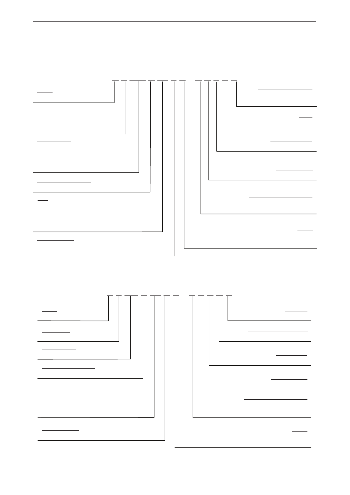
Nomenclature
Indoor
M 5 WM Y 10 L R – A C B D D
Brand
M: McQuay
Refrigerant
5: R410A
Product Specification
Variation
D: Fourth Issue
Grille
D: Grille D
Product Type
WM: Wall Mounted
CK : Ceiling Cassette
CC: Ceiling Concealed
CM: Ceiling Mounted
Inverter System Type
Y: Y Series
Size
10 :
10,000 Btu/h
§
15,000 Btu/h
15 :
§
20,000 Btu/h
20 :
§
25 :
20,000 Btu/h
§
Product series
L: L series J: J series
C: C Series E: E series
Outdoor
Brand
M: McQuay
M 5 MS Y 18 B R – A C D O A
Type of Air Filte
B: Bio Filter
Market Region
C: Export with CE Markin
Electrical Characteristics
A : 50Hz / 1Ph / 220-240V
F : 50Hz / 3Ph / 380-415V
Model
“ ”: Cooling Only
Product Specification
R: Heat Pump
Variation
A: First Issue
Refrigerant
5: R410A
Product Type
MS: Multi Split Condensing Unit
Inverter System Type
Y: Y Series
Size
18 :
18,000 Btu/h
§
20 :
20,000 Btu/h
§
25,000 Btu/h
25 :
§
30 :
30,000 Btu/h
§
Product series
B: B Series
1
Specifications Variation
O: Standard Unit
Compresso
D: Daikin Compresso
Market Region
C: Export with CE Markin
Electrical Characteristics
A : 50Hz / 1Ph / 220-240V
F : 50Hz / 3Ph / 380-415V
Model
“ ”: Cooling Only
R: Heat Pump
Page 4
M5MSY_(i) Nomenclature
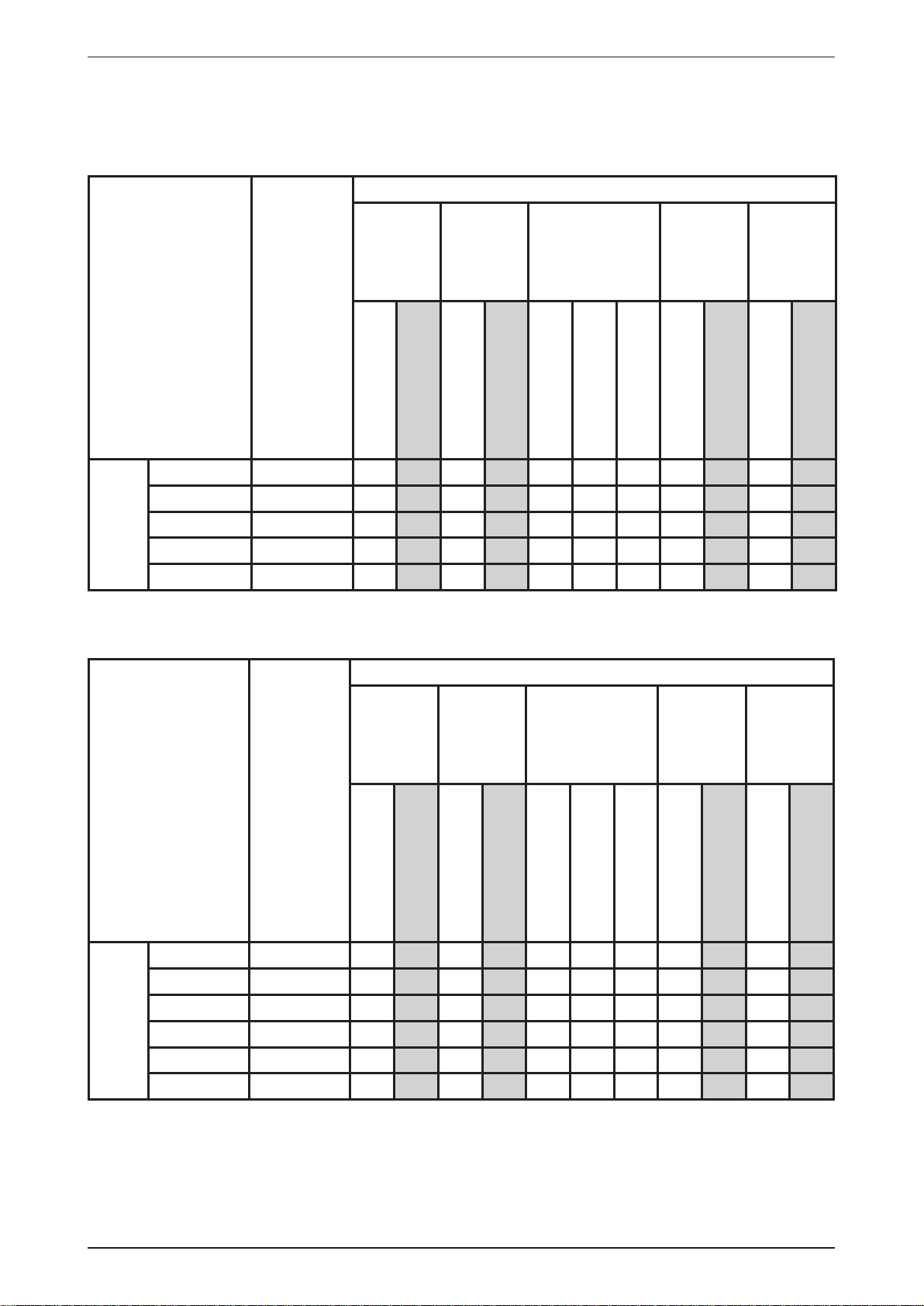
Product Line-Up
Indoor Unit
M5WMY-L Series/J Series
Classifi cation
M5WMY
10LR ACBDD X X X X X X X
15LR ACBDD X X X X X X X
10JR ACLAD X X X X X
15JR ACLAD X X X X X
HEATPUMP
20JR ACLTC X X X X X
Indoor Unit
M5CKY-C Series
Nomenclature
GS01
Handset
PCB
W_2_03A
Air
Purifi cation
Saranet Filter
Bio Antibody Filter
Classifi cation
Marking
Titanium Apatite
Filter
CE
Others
Auto Restart
Handset
M5CKY
Nomenclature
GS01
10CR ACOA X X X
15CR ACOA X X X
20CR ACOA X X X
HEATPUMP
PLCKYCR NGS01 X X X
PCB
C_2_01A_M
Air
Purifi cation
Saranet Filter
Negative Ionizer
Nano Technology Air
Filtration
CE
Marking
Others
Auto Restart
2
Page 5
Nomenclature M5MSY_(i)
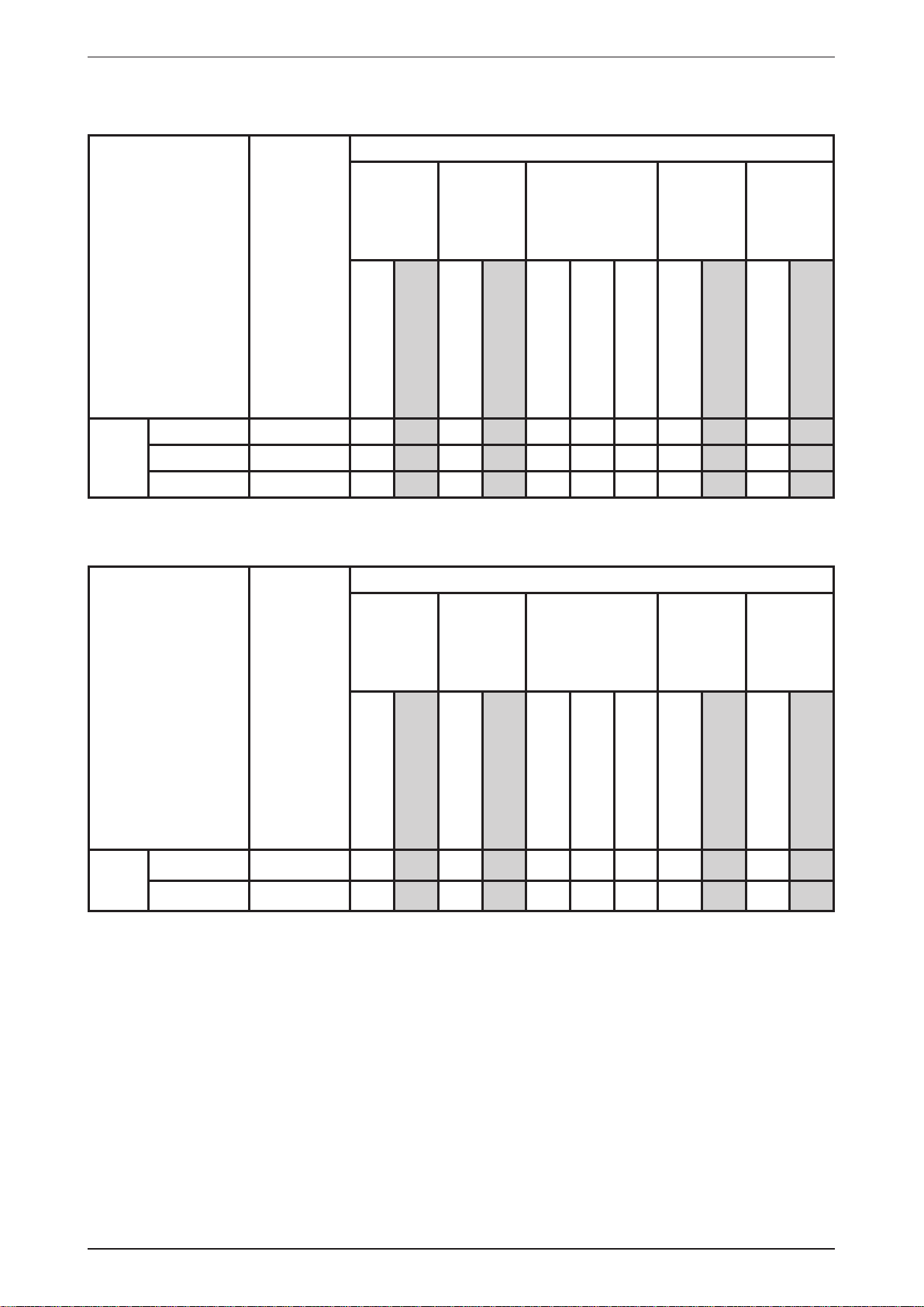
Indoor Unit
M5CCY-C Series
Classifi cation
M5CCY
10CR ACPA X X X X X
15CR ACPA X X X X X
HEAT-
PUMP
20CR ACPA X X X X X
Indoor Unit
M5CMY-E Series
Nomenclature
Netware 3C
Handset
Handset
PCB
C_2_01A_M
PCB
Air
Purifi cation
Saranet Filter
Negative Ionizer
Classifi cation
Air
Purifi cation
Nano Technology Air
Filtration
CE
Marking
Marking
Others
Auto Restart
Others
M5CMY
Nomenclature
GS01
15ER ACAA X X X X X
20ER ACAA X X X X X
HEAT-
PUMP
C_2_01A_M
Saranet Filter
Negative Ionizer
Nano Technology Air
Filtration
CE
Auto Restart
3
Page 6
M5MSY_(i) Nomenclature
Outdoor Unit
M5MSY-BR
Classifi cation
Refrigerant
M5MSY
18BR ACDOA
20BR ACDOA
25BR ACDOA
30BR ACDOA
HEATPUMP
Nomenclature
Cap Tube
Control
EXV
XX XXX
XX XXX
XX XXX
XX XXX
Fin
Gold coated
Blue coated
Bare
ContactorHPLP
Safety
Devices
Compressor
DC Inverter SwingCEDrain Elbow
Marking
Others
* Remark : M5MSY18BR is not recommended to couple with M5WMY10/15 JR (for Wall Mounted series).
M5MSY18BR is recommended to couple with M5WMY10/15 LR (for Wall Mounted series).
4
Page 7
Application Information M5MSY_(i)
Application Information
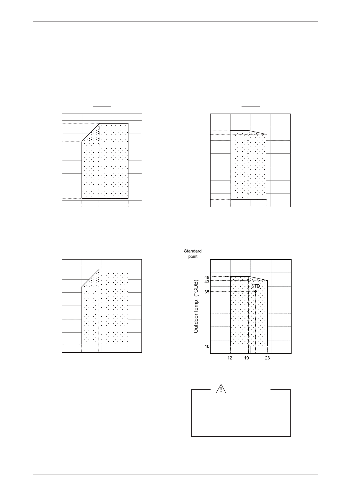
Operating Range
Ensure the operating temperature is in allowable range.
Heatpump - M5MSY20/25/30BR
Heating
18
10
Outdoor temp. (°CWB)
-16
15 20
Indoor temp. (°CDB)
Heatpump - M5MSY18BR
Heating
18
27
Standard
point
Cooling
46
43
Outdoor temp. (°CDB)
0
12 2319
Indoor temp. (°CWB)
Cooling
10
Outdoor temp. (°CWB)
-16
15 20
Indoor temp. (°CDB)
27
Indoor temp. (°CWB)
Caution :
The use of your air conditioner
outside the range of working
temperature and humidity can result
in serious failure
.
5
Page 8
M5MSY_(i) Application Information
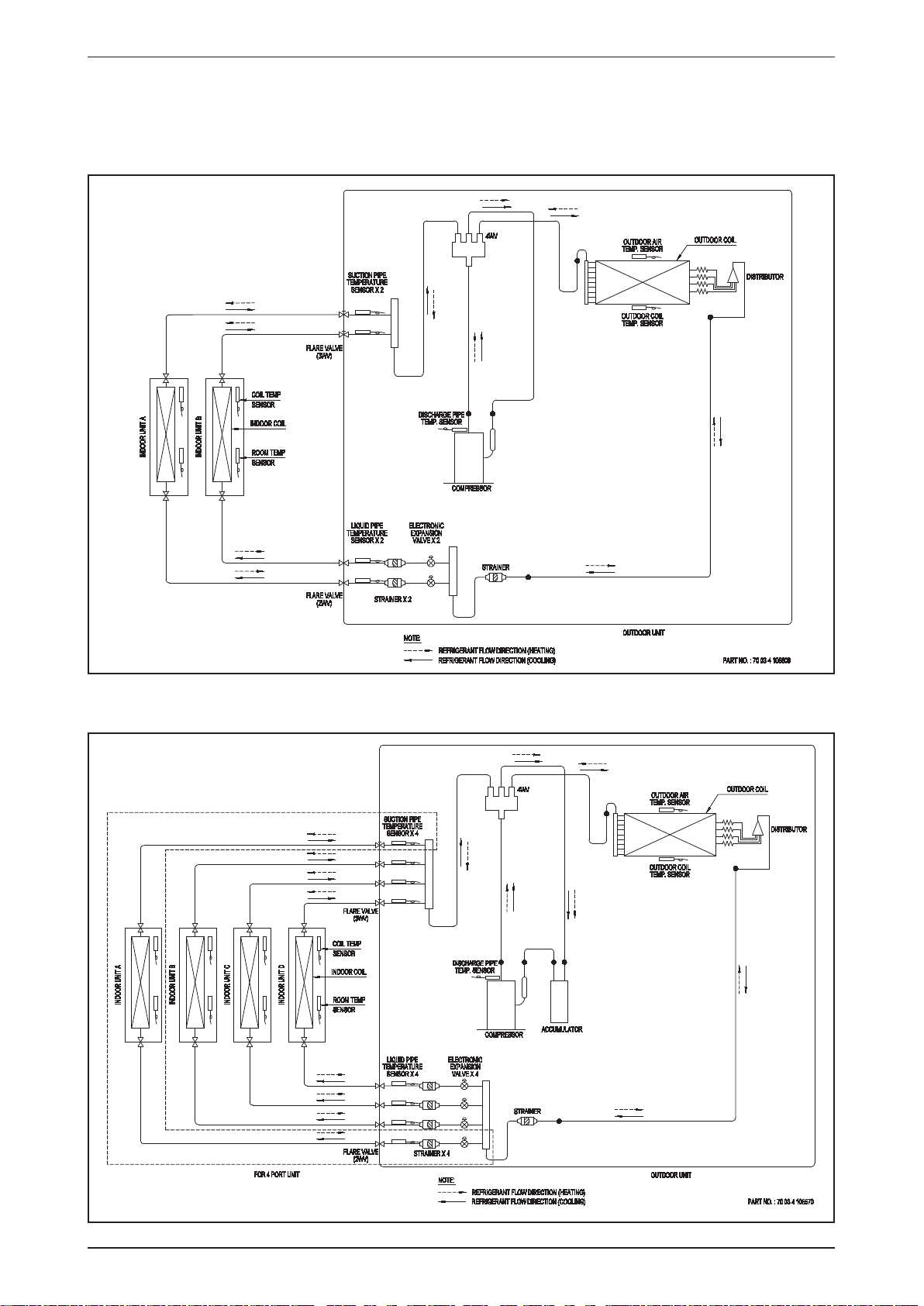
Refrigerant Circuit Diagrams
Model: M5MSY18BR
M5MSY20BR
Model: M5MSY25BR
M5MSY30BR
6
Page 9
Application Information M5MSY_(i)
Installation Guideline
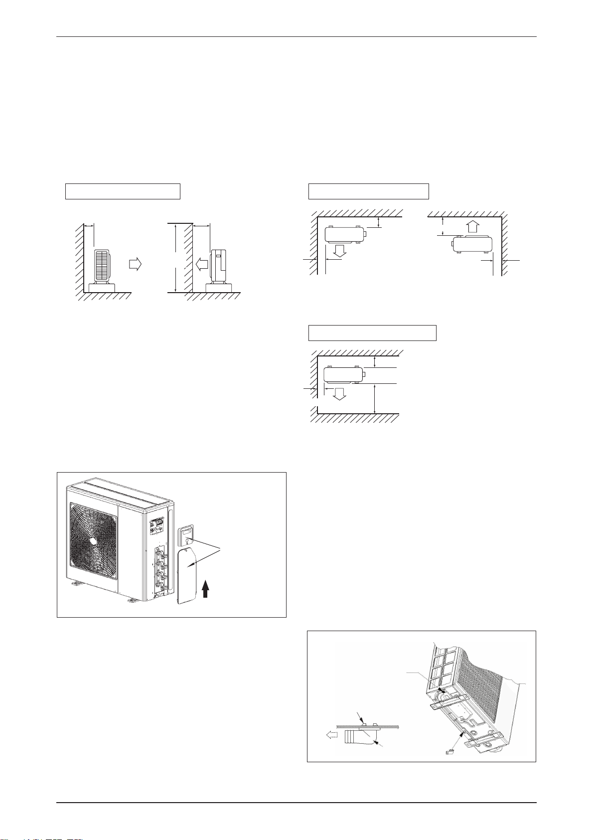
Installation of Outdoor Unit
• The outdoor unit must be installed in such a way, so as to prevent short circuit of the hot discharged air or
obstruction to the smooth air fl ow. Please follow the installation clearance shown in the fi gures below. Select
the coolest possible place where intake air temperature is not greater than the outside air temperature
(maximum 45°C/113°F)
• Where a wall or other obstacle is in the path of outdoor unit’s intake or exhaust airfl ow, follow the installation
guidelines below.
• For any of the below installation patterns, the wall height on the exhaust side should be 1200mm or less.
Wall facing two sidesWall facing one side
More than 100
Side View
More than 350
1200
or less
More than 50
More
than 100
More than 350
More than 50
Top Vie w
Wall facing three sides
More than 100
More than 50
More than 350
Top View
Unit : mm
• Before installing the piping and connecting cord, please remove the access panel and plastic valve cover for
easy access. Refer to fi gures shown below.
PLEASE REMOVE
ACCESS PANEL &
PLASTIC VALVE
COVER WHEN
CONNECTING
THE PIPING AND
CONNECTING
CORD.
PUSH & PULL UP
• There are 2 holes on the base of Outdoor Unit for
condensed water to fl ow out. Insert the drain elbow
to one of the holes.
• To install the drain elbow, fi rst insert one portion
of the hook to the base (portion A), then pull the
drain elbow in the direction shown by the arrow
while inserting the other portion to the base. After
installation, check to ensure that the drain elbow
clings to base fi rmly.
• If the unit is installed in a snowy and chilly area,
condensed water may freeze in the base. In such
case, please remove plug at the bottom of unit to
smooth the drainage.
7
BASE
Plug
A
DRAIN
ELBOW
DRAIN
ELBOW
Page 10
M5MSY_(i) Application Information
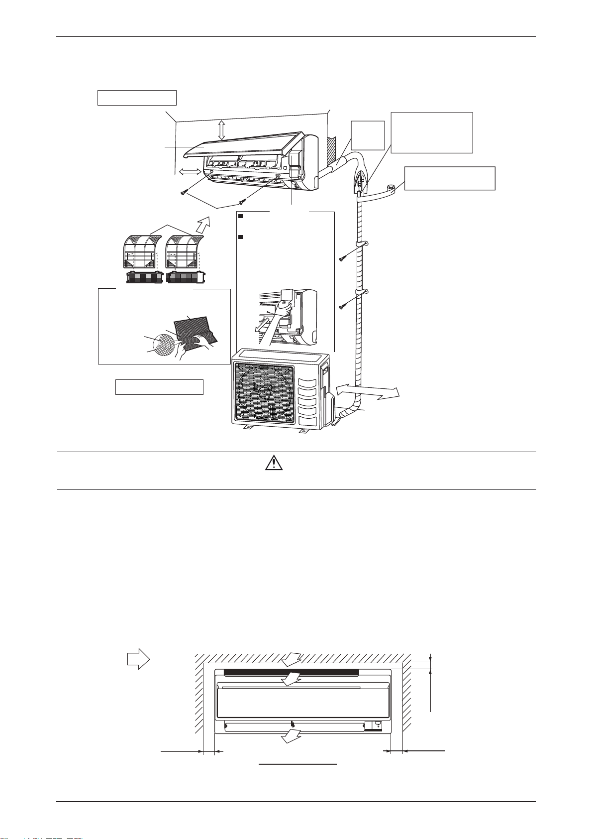
Installation Diagram
Wall Mounted
Indoor Unit
Cut thermal insulation
pipe to an appropriate
length and wrap it with
tape, making sure that no
gap is left in the insulation
pipe's cut line.
Wrap the insulation pipe with
the finishing tape from bottom
to top.
Front panel
50mm or more from walls
(on both sides)
30mm or more from ceiling
Caulk pipe
hole gap
with putty.
Air filter
Air-Purifying Filter with
bacteriostatic virustatic function (2)
Air-Purifying Filter with
bacteriostatic virustatic
function
Filter frame
Tab
Air filter
Outdoor Unit
M4 x 12L
Opening service lid
Service lid
Service lid is opening/closing
type.
Opening method
1) Remove the service lid
screws.
2) Pull out the service lid
diagonally down in
the direction of the arrow.
1) Pull down.
250mm from wall
Caution
Before installing the unit, ensure that the power supply matches the power requirement of the air conditioner.s
Installation of Indoor Unit
Service Space
Install the indoor unit at a location with the following requirements
• Location is suitable for wiring, piping and drainage.
• No obstruction of air fl ow into and out of unit where cooler air can be evenly distributed.
• Ensure that air discharge is not short circuited with air intake.
• Ensure that wall is suffi ciently strong, rigid, fl at, perpendicular and vibration free.
• Where air fi lter cassette can be slided in or out easily.
• Where there is no danger of fl ammable gases.
• Where there is no direct sunlight on unit.
Air flow
(Indoor)
min. 50
(Space for
maintenance)
Required space
min. 50
(Space for
maintenance)
rofecapS(
03.nim
)ecnamrofrep
8
Page 11
Application Information M5MSY_(i)
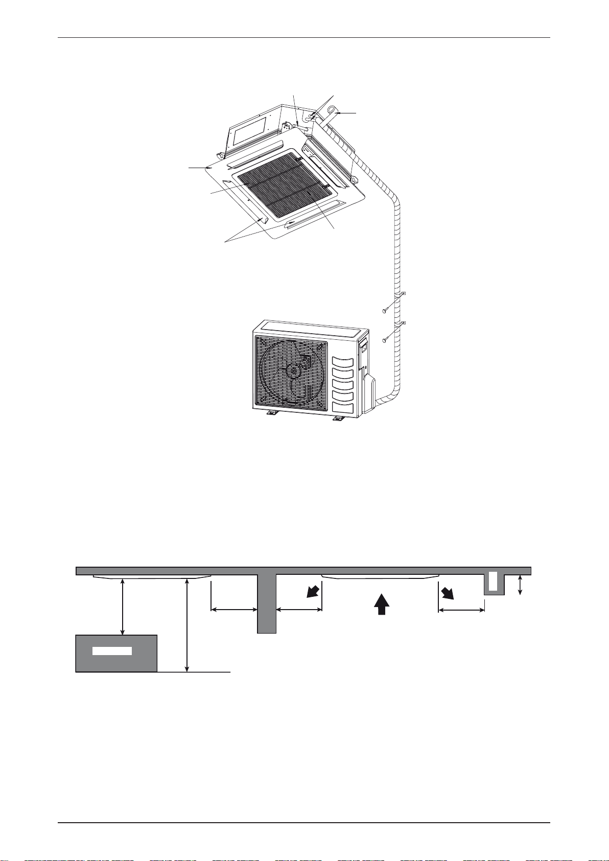
Ceiling Cassette
Front Panel
Air Filter
(behind the grille)
Air Discharge Louver
Drain Piping
Thermal Insulation
Wrap the insulated pipe with the
finishing tape from bottom to top
Air Intake Grille
Preliminary Site Survey
• Electrical supply and installation is to confi rm to local authority’s (e.g. National Electrical Board) codes and
regulations.
• Voltage supply fl uctuation must not exceed ± 10% of rated voltage. Electricity supply lines must be
independent of welding transformers which can cause high supply fl uctuation.
• Ensure that the location is convenient for wiring, piping and drainage.
• The indoor unit must be installed in such that free from any obstacles in path of cool air discharge and
warm air return, and must allow spreading or air throughout the room (near the centre of the room).
• Clearance must be provided for the indoor unit from the wall and obstacles as shown in the fi gure.
Beam
Min 0.5 m Min 0.5 m
Min 1.0 m
Obstacles
Max 3.0 m
Floor
• The installation place must be strong enough to support a load of 4 times the indoor unit weight to avoid
amplifying noise and vibration.
• The installation place (handling ceiling surface) must be level and the height in the ceiling is 350mm or
more.
Min 0.5 m
Max 3.0 m
9
Page 12

M5MSY_(i) Application Information
Unit Installation
15.0
38.0
505.0
32.0
580.0 ~ 610mm (CEILING OPENING MEASUREMENT)
538.0
18.0
)TNEMERUSAEMGNINEPOGNILIEC(mm016~0.085
88.0448.0
19.0529.0
M5CKY-C
• The indoor unit must be away from heat and steam sources (avoid installing it near an entrance).
• Measure and mark the position for the hanging rod. Drill the hole for the angle nut on the ceiling and fi x
the hanging rod.
• The installation template is extended according to temperature and humidity. Check on dimensions in
using.
• The dimensions of the installation template are same as those of the ceiling opening dimensions.
• Before ceiling laminating work is completed, be sure to fi t the installation template to the indoor unit.
Note: Be sure to discuss the ceiling drilling work with the installers concerned.
Unit Hanging
Indo or U nit
Ceiling
Bo
ard
30.0mm
M5CKY-C/E
• Confi rm the pitch of the hanging rod is 770mm x 622mm sharp (M5CKY-E)
• Hold the unit and hand it on the hanging rod with the nut and washer.
• Adjust the unit height to 35.0mm between the indoor unit bottom surface and the ceiling surface.
• Confi rm with a level gauge that the unit is installed horizontally and tighten the nut and bol to prevent unit
falling and vibration.
Open the ceiling board along the outer edge of the paper installation template.
•
10
Page 13
Application Information M5MSY_(i)
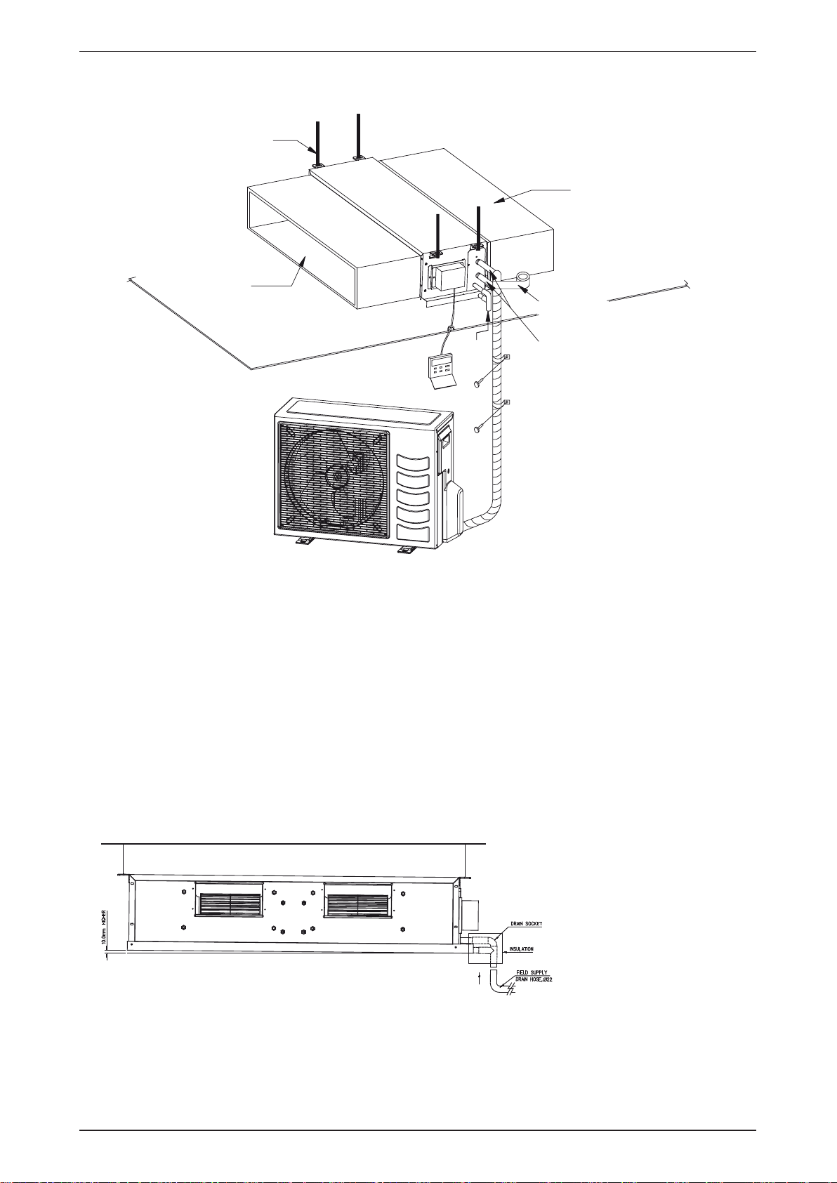
Ceiling Concealed
Hanger
Return duct
Supply duct
Wrap the insulated pipe with the
finishing tape from bottom to top
Ceiling
Drain
piping
Thermal insulation
Preliminary Survey
• Electrical supply and installation is to confi rm to local authority’s (e.g. National Electrical Board) codes and
regulations.
• Voltage supply fl uctuation must not exceed ± 10% of rated voltage. Electricity supply lines must be
independent of welding transformers which can cause high supply fl uctuation.
• Ensure that the location is convenient for wiring, piping and drainage.
• The indoor unit must be installed in such that free from any obstacles in path of cool air discharge and
warm air return, and must allow spreading or air throughout the room (near the centre of the room).
• Clearance must be provided for the indoor unit from the wall and obstacles as shown in the fi gure.
• Use the hanger supplied with the unit.
• Ensure the support is strong enough to withstand the weight of the unit.
• Use the supplied drain socket to connect the drain pipe
11
Install the unit in such a way that
the condensate water can flow
out smoothly.
Page 14
M5MSY_(i) Application Information
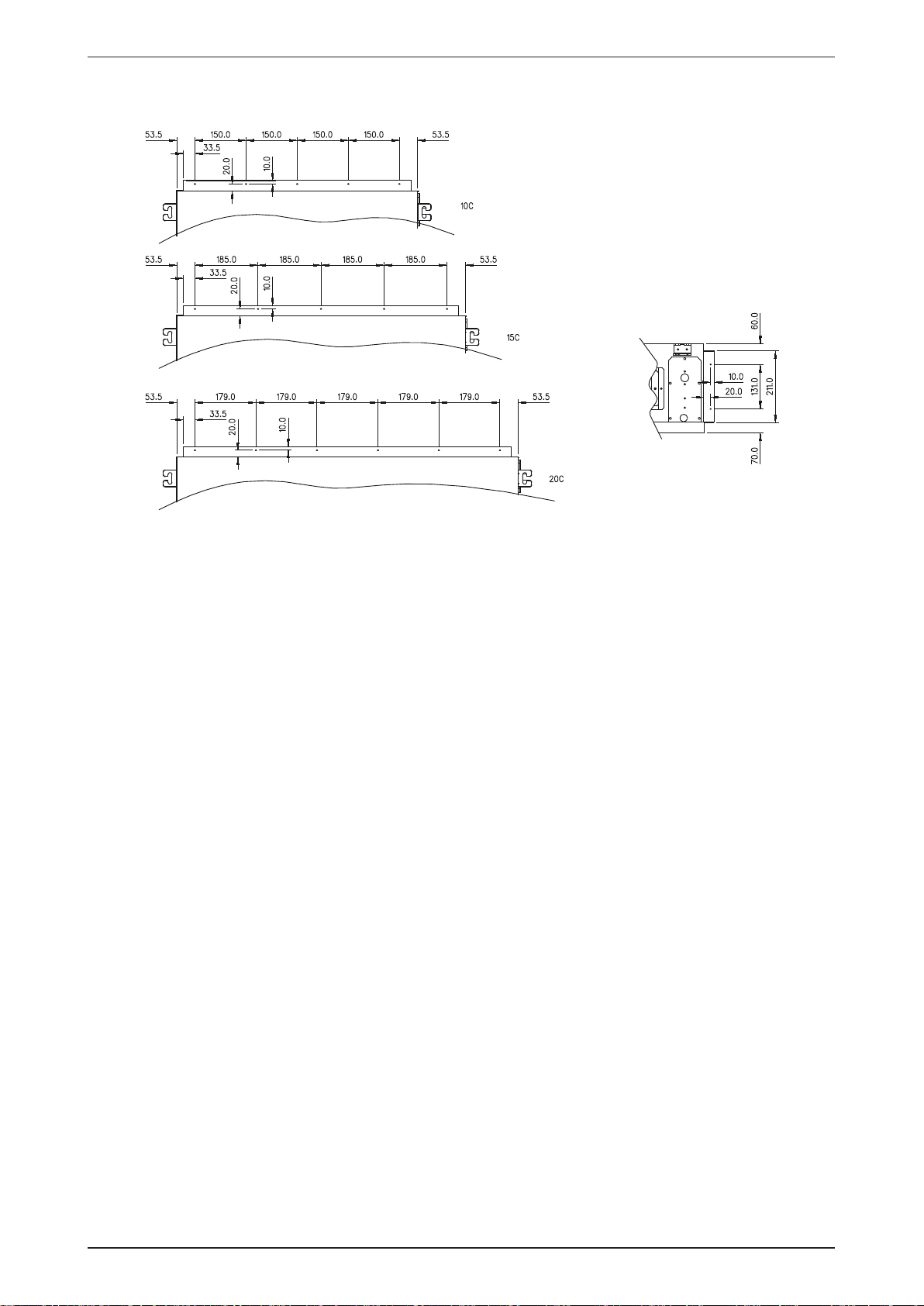
The diagrams below show the screws position for duct work connection.
12
Page 15
Application Information M5MSY_(i)
Ceiling Convertible
Preliminary Site Survey
• Electrical supply and installation is to confi rm to local authority’s (e.g. National Electrical Board) codes and
regulations.
• Voltage supply fl uctuation must not exceed ± 10% of rated voltage. Electricity supply lines must be
independent of welding transformers which can cause high supply fl uctuation.
• Ensure that the location is convenient for wiring, piping and drainage.
Standard Mounting
Ensure that the overhead supports are strong enough to hold the weight of the unit. Position the hanger rods
(wall mounting bracket for fl oor standing), and check for its alignment with the unit as shown in Fig. below.
Also,check that the hangers are secured and the base of the fan coil unit is leveled in both horizontal
directions, taking into account the gradient for drainage fl ow as recommended under section Piping and
Drain Hose Installation.
13
Page 16
M5MSY_(i) Application Information
Please ensure that the following steps are taken:
• Check the gradient for drainage fl ow as recommended in Figure A.
• Provide clearance for easy servicing and optimal air fl ow as shown in Figure B.
• The indoor unit must be installed such that there is no short circuit of the cool discharge air with the warm
return air.
• Do not install the indoor unit where there is direct sunlight shining on the unit. The location should be suitable for piping and drainage installation. The unit must be a large distance away from the door.
Fig.A
Under ceiling type
Floor standing type
Fig.B
14
Page 17
Application Information M5MSY_(i)
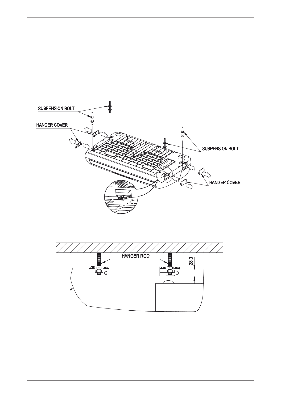
Under Ceiling Installation
Install the Suspension Bolts
1. Install the suspension bolts so that it can support the indoor unit.
2. Adjust the distance to ceiling before installation.
3. Refer to the dimension given to install the unit.
Install the Indoor Unit
1. Insert the suspension bolts into the fi ttings of the hanger bracket.
2. Set the nuts and washer on the both side of the metal fi ttings.
3. Secure it with nuts.
4. Attach the hanger cover (4 pcs) to the units.
15
Page 18
M5MSY_(i) Application Information
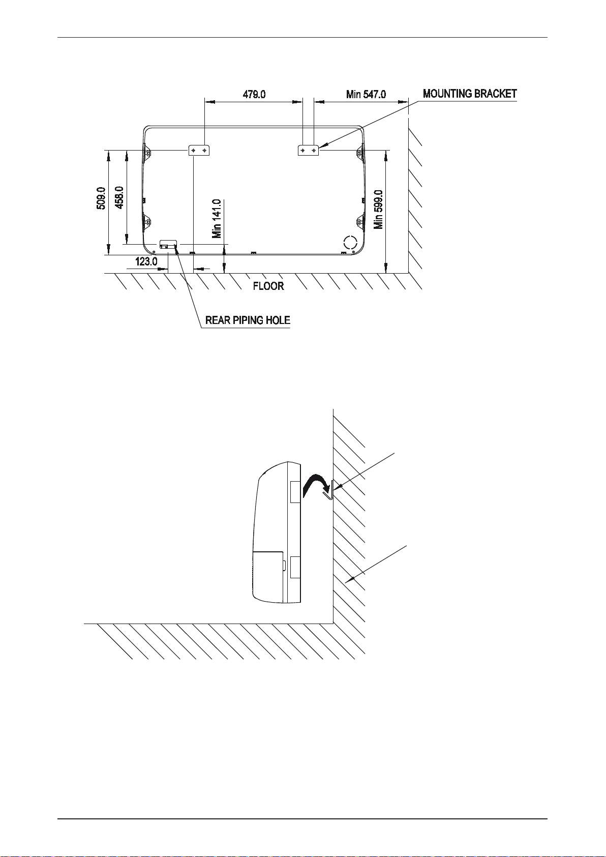
Floor Standing Installation
1. Refer to the dimension as illustrated when installing the mounting bracket.
2. Determine the pipe hose position using the rear piping hole. Drill the pipe hole at the slight downward
slant to the outdoor side.
MOUNTING BRACKET
HOCK THE UNIT ON THE
MOUNTING BRACKET
WALL
16
Page 19
Application Information M5MSY_(i)
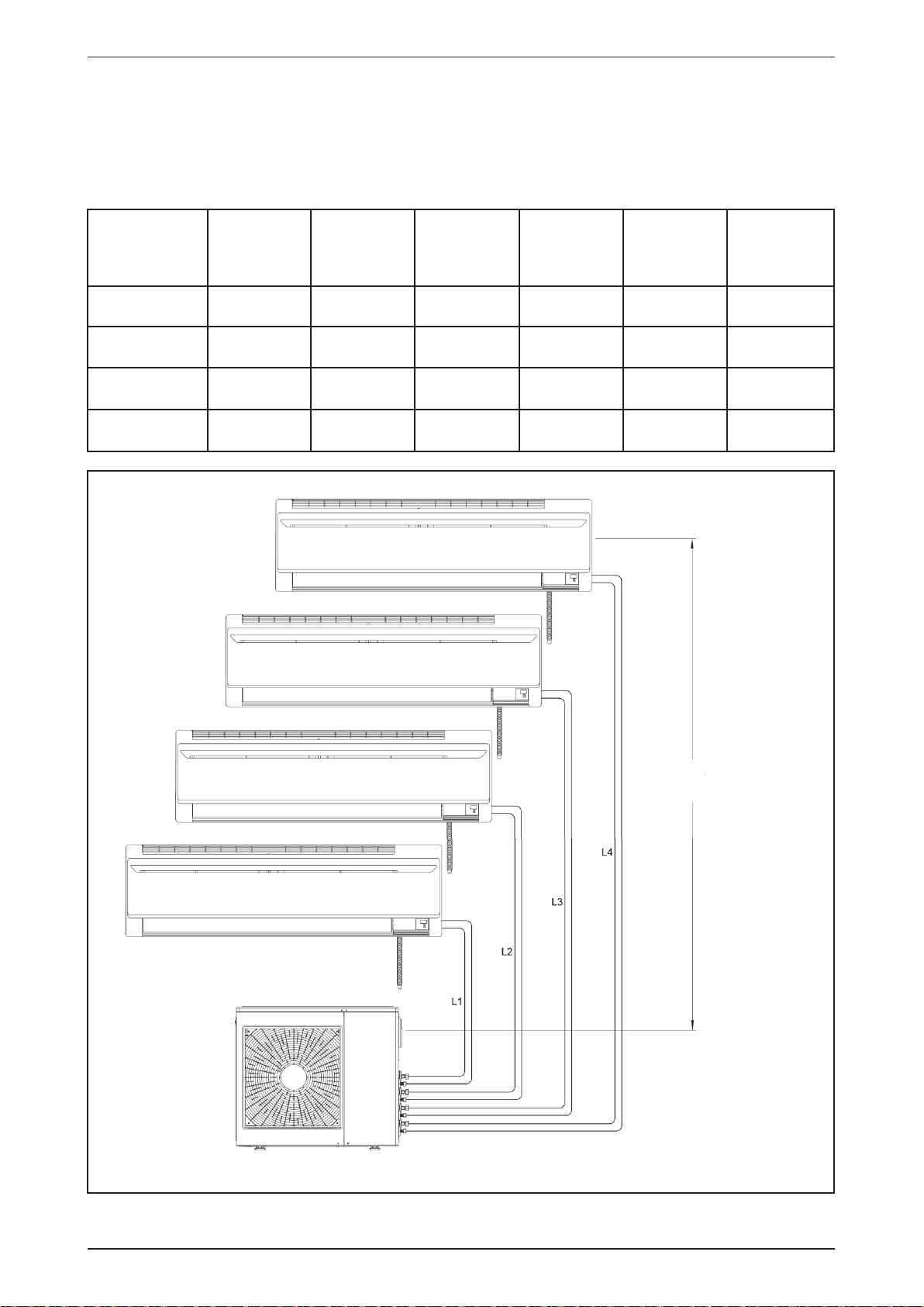
REFRIGERANT PIPING
Piping Length & Elevation
If the pipe is too long, both capacity and reliability of the unit will drop. As the number of bends increases,
resistance to the fl ow of refrigerant system increases, thus lowering cooling capacity. As a result, the
compressor may become defective. Always choose the shortest path and not exceed the maximum piping
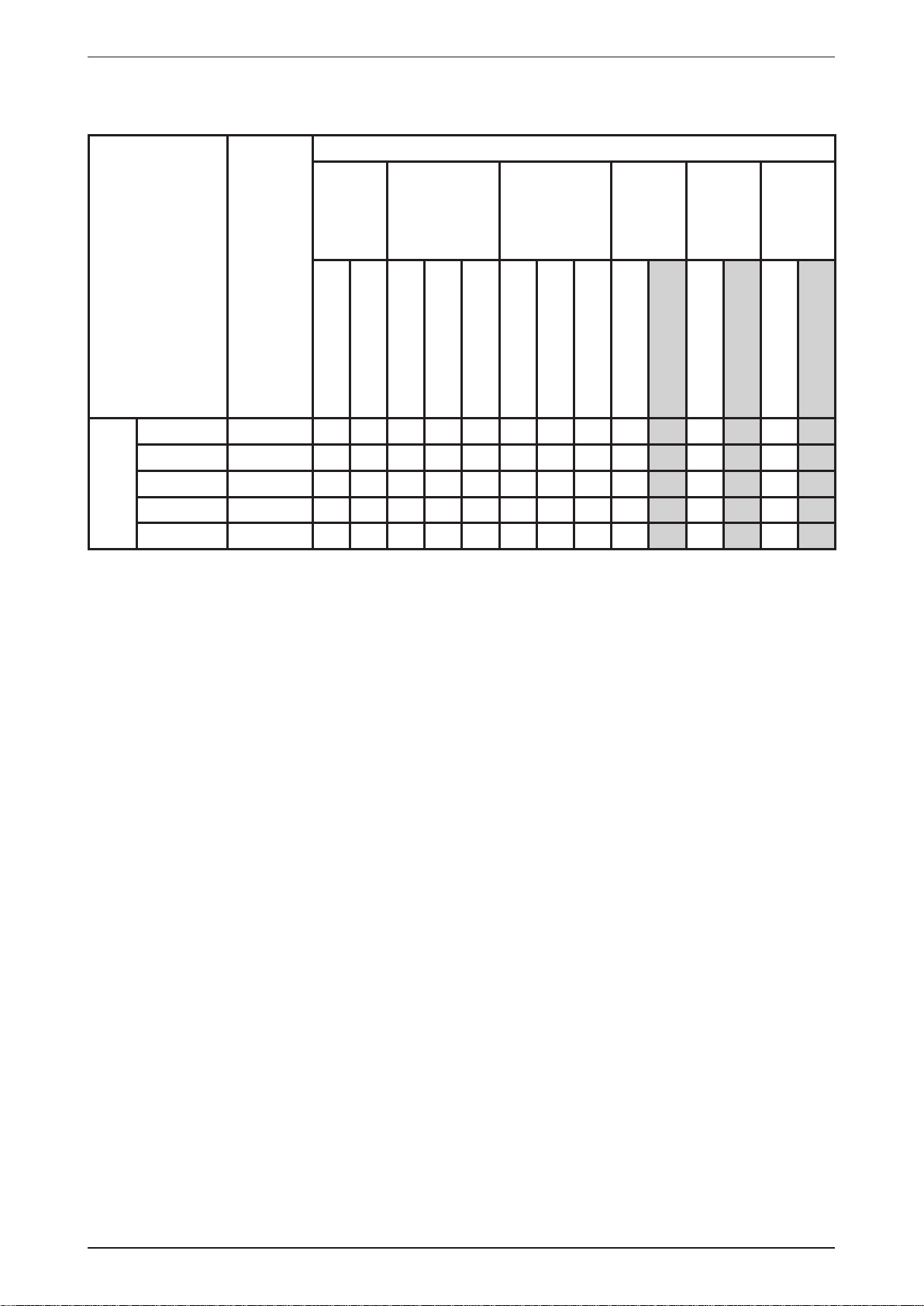
length as tabulated below.
Single Indoor
Maximum
Piping
Length(m)
Maximum
height
Difference(m)
Pre-charged
Total Piping
length (m)
Outdoor Unit
Pre-charged
(kg)
1.2 20
L ≤ 25 H ≤ 15 30 2.6 20
4
L ≤ 25 H ≤ 15 30 2.6 20
Amount of
Additional
Charge (g/m)
Model
M5MSY18BR
(2 Ports)
M5MSY20BR
(2 Ports)
M5MSY25BR
(3 Ports)
M5MSY30BR
(4 Ports)
Maximum
Total Piping
Length (m)
L
+ L2 ≤ 30 L ≤ 20 H ≤ 15 15
1
L1+ L2 ≤ 50 L ≤ 25 H ≤ 15 30 2.0 20
L
+ L2+ L3 ≤
1
60
L
+ L2+ L3+ L
1
≤ 60
VERTICAL HEIGHT
DIFFERENCE MAX. H
INDOOR UNIT
OUTDOOR UNIT
* Remark : Applicable for Wall Mounted, Ceiling Cassette, Ceiling Concealed, Ceiling Convertible unit.
17
Page 20
M5MSY_(i) Application Information
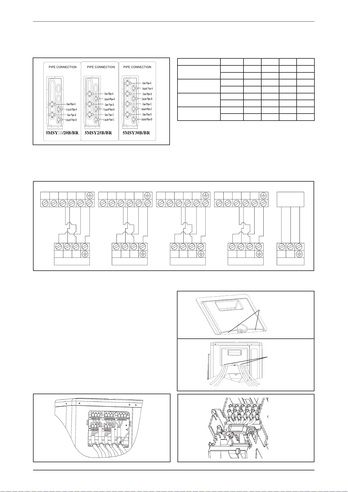
Piping Connection To The Units
• The outdoor unit is equipped with two to four sets of fl are joints depending on O/D unit model. Refer to the
table below for fl are joint size and location.
Model Pipe A B C D
M5MSY18BR
M5MSY20BR
M5MSY25BR
M5MSY30BR
18
ELECTRICAL WIRING CONNECTION
IMPORTANT: The fi gures shown in the table are for information purpose only. They should be checked and
selected to comply with the local/national codes of regulations. This is also to the type of
installation and conductors used.
Liquid 1/4” 1/4” - -
Gas 3/8” 3/8” - -
Liquid 1/4” 1/4” - -
Gas 1/2” 1/2” - -
Liquid 1/4” 1/4” 1/4” -
Gas 3/8” 1/2” 1/2” -
Liquid 1/4” 1/4” 1/4” 1/4”
Gas 3/8” 3/8” 1/2” 1/2”
Indoor Unit A Indoor Unit B Indoor Unit C Indoor Unit D
1 2 SIG N L
SIGNLNLNLNLNL
0
There must be a double pole switch with a minimum 3 mm contact gap and fuse/ circuit breaker as
SIG
1 2 SIG N L1 2 SIG N L
SIG SIG
1 2 SIG N L
DCBA
Power
Supply
Power Supply
recommended in the fi xed installation circuit.
• All wiring must be connected accordingly to the diagram
above, with reference to the piping connection. Mismatch
any wiring with different piping will cause severe damage
to the system.
• All wires must be fi rmly connected.
• All wires must not touch the refrigerant piping, compressor
or any moving parts of the fan motor.
• The connecting wires between the indoor unit and the
outdoor unit must be clamped on the wire clamps and the
cable tie (push releasable) at the indoor unit and outdoor
unit respectively as shown in the fi gures.
• The power supply cord must be equivalent to H07RN-F
(245IEC57) or higher.
• Remove the detachable part of the access cover to allow
wire routing.
• All wires must not be clamped by the access panel cover.
Detachable part
Wires
mustn't be
clamped
Wire Clamp
Interconnection
Cable
18
Page 21
Application Information M5MSY_(i)
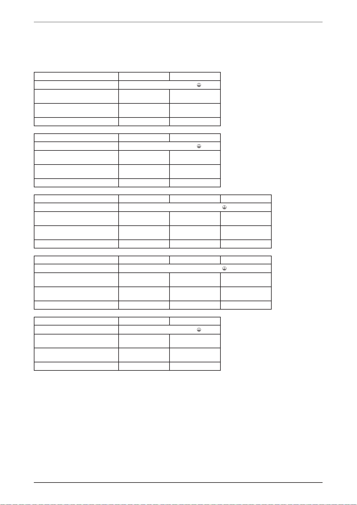
* The fi gures shown in the table are for information purpose only. They should be checked and selected
to comply with the local/national codes of regulations. This is also subject to the type of installation and
conductors used.
** The appropriate voltage range should be checked with label data on the unit.
Model M5WMY10 LR M5WMY15 LR
Voltage Range**
Power supply cable size* mm
2
Number of core
Interconnection cable size* mm
2
Number of core
Recommended time delay fuse* A 25 25
Model M5WMY10/15 JR M5WMY20 JR
Voltage Range**
Power supply cable size* mm
2
Number of core
Interconnection cable size* mm
2
Number of core
Recommended time delay fuse* A 25 25
220V - 240V / 1Ph / 50Hz+
3.0
3.0
3
1.5
1.5
4
220V - 240V / 1Ph / 50Hz+
3.0
3.0
3
1.5
2.5
4
3
4
3
4
Model M5CKY10 C/CR M5CKY15 C/CR M5CKY20 C/CR
Voltage Range**
Power supply cable size* mm
Number of conductors
Interconnection cable size* mm
Number of conductors
2
3.0
3
2
1.5
4
220V - 240V / 1Ph / 50Hz+
3.0
3
1.5
4
3.0
3
2.5
4
Recommended time delay fuse* A 25 25 25
Model M5CCY10 C/CR M5CCY15 C/CR M5CCY20 C/CR
Voltage Range**
Power supply cable size* mm
Number of conductors
Interconnection cable size* mm
Number of conductors
2
3.0
3
2
1.5
4
220V - 240V / 1Ph / 50Hz+
3.0
3
1.5
4
3.0
3
2.5
4
Recommended time delay fuse* A 25 25 25
Model M5CMY15 E/ER M5CMY20 E/ER
Voltage Range**
Power supply cable size* mm
Number of conductors
Interconnection cable size* mm
Number of conductors
2
2
220V - 240V / 1Ph / 50Hz+
3.0
3.0
3
1.5
2.5
4
3
4
Recommended time delay fuse* A 25 25
19
Page 22

M5MSY_(i) Engineering & Physical Data
Engineering & Physical Data
Engineering Data - M5MSY - B Series (R410A model)
MODEL
NOMINAL COOLING CAPACITY
NOMINAL HEATING CAPACITY
NOMINAL TOTAL INPUT POWER (COOLING) W
NOMINAL TOTAL INPUT POWER (HEATING) W
NOMINAL RUNNING CURRENT (COOLING) A
NOMINAL RUNNING CURRENT (HEATING) A
EER W/W
COP W/W
REFRIGERANT CHARGE kg
POWER SOURCE V/Ph/Hz 220 - 240 / 1 / 50
REFRIGERANT TYPE
AIR FLOW l/s / CFM 512/1076 780 / 1638 850 / 1786
SOUND PRESSURE LEVEL dBA 47 48 49
UNIT DIMENSION HEIGHT X WIDTH X DEPTH mm 550 x 765 x 285 756 x 855 x 328
PACKING DIMENSION HEIGHT X WIDTH X DEPTH mm 610 x 895 x 360 793 x 990 x 415
UNIT WEIGHT kg 34 45 55
TYPE FLARE
PIPE
CONNECTION
FAN
FAN MOTOR
OUTDOOR UNIT
COMPRESSOR
COIL
CASING COLOUR LIGHT GREY
DRAWING NUMBER 0453103CV18 0453103CV20 0453103CV25 0453103CV30
SIZE
TYPE PROPELLER
DRIVE DIRECT
TYPE DC BRUSHLESS
INDEX OF PROTECTION (IP) IP23 IP34
INSULATION GRADE Class E
RATED INPUT POWER W 35 61 79
RATED RUNNING CURRENT A 0.38 0.73 0.91
MOTOR OUTPUT W 50 61
TYPE HERMATIC SWING COMPRESSOR
OIL TYPE DAPHNE FVC50K POLYESTER OIL (PVE)
OIL AMOUNT cm
RATED INPUT POWER (COOLING) W - 1183 1420
RATED INPUT POWER (HEATING) W - 1264 1491
RATED RUNNING CURRENT
(COOLING)
RATED RUNNING CURRENT
(HEATING)
TUBE
FIN
OUTDOOR UNIT M5MSY18BR M5MSY20BR M5MSY25BR M5MSY30BR
TYPE 1-to-2 1-to-3 1-to-4
Btu/h 13650 (4400 ~15350) 18400 (5100 - 21200) 22200 (3400 - 26100) 26100 (4100 - 31000)
W 4000 (1300 ~ 4500) 5400 (1500 - 6200) 6500 (1000 - 7650) 7650 (1200 - 9100)
15000 (2700 ~ 17400)
Btu/h
4400 (800 ~ 5100)
W
1050 (330 ~ 1400)
1040 (250 ~ 1450)
4.82 (1.97 ~ 6.33)
4.76 (1.45 ~ 6.50)
3.81
4.23
1.20
LIQUID mm 2 x 6.35 3 x 6.35 4 x 6.35
GAS mm 2 x 9.52 2 x 12.7
3
A - 4.69 6.7
A - 4.09 5.58
MATERIAL
DIAMETER mm 7
MATERIAL
FACE AREA m
ROW 2
2
450 650 750
INNER GROOVE
COPPER
0.405 0.62
21800 (2400 - 23500) 25200 (3100 - 28000) 28700 (3100 - 30700)
6400 (700 - 6900) 7400 (900 - 8200) 8400 (900 - 9000)
1378 (380 ~ 1720) 1702 (400 ~ 2370) 2113 (430 ~ 2950)
1492 (270 ~ 1680) 1749 (350 ~ 2130) 2054 (380 ~ 2550)
6.15 (2.88 ~ 7.58) 7.58 (2.94 ~ 10.47) 9.30 (3.13 ~ 12.91)
6.62 (2.03 ~ 7.46) 7.72 (2.59 ~ 9.41) 8.98 (2.70 ~ 11.16)
3.91 3.82 3.62
4.28 4.23 4.09
2.00 2.6
R410A
1 x 9.52
2 x 12.7
SEAMLESS INNER GROOVE COPPER
ALUMINIUM
(HYDROPHILIC FIN)
1) ALL UNITS ARE BEING TESTED AND COMPLY TO ISO 5151 (NON-DUCTED UNIT) OR ISO 13253 (DUCTED UNIT).
2) ALL SPECIFICATIONS ARE SUBJECTED TO CHANGE BY THE MANUFACTURER WITHOUT PRIOR NOTICE.
3) A5MSY18BR IS APPLICABLE WITH 5WMY10/15 LR BUT NOT WITH 5WMY10/15 JR (FOR WM UNIT).
COOLING HEATING
INDOOR: 27°C DB / 19°C WB INDOOR: 20°C DB
OUTDOOR: 35°C DB / 24°C WB OUTDOOR: 8°C DB / 6°C WB
20
Page 23

Engineering & Physical Da M5MSY_(i)
Engineering Data - M5WMY - L Series (R410A model)
MODEL INDOOR UNIT M5WMY10LR M5WMY15LR
CONTROL
AIR FLOW
SOUND PRESSURE LEVEL (SH/H/M/L/SL) dBA 41 / 40 / 34 / 29 / 21 42 / 41 / 34 / 30 / 22
UNIT DIMENSION HEIGHT X WIDTH X DEPTH mm 288 X 800 X 206
PACKING DIMENSION HEIGHT X WIDTH X DEPTH mm 350 x 894 x 280
UNIT WEIGHT kg 9
CONDENSATE DRAIN SIZE mm 19
FAN
INDOOR UNIT
FAN MOTOR
COIL
AIR QUALITY FILTER
CASING COLOUR WHITE
DRAWING NUMBER 0453103CW10 0453103CW15
AIR DISCHARGE
OPERATION WIRELESS REMOTE CONTROL
TURBO l/s / CFM 178 / 378 185 / 392
HIGH l/s / CFM 163 / 345 169 / 358
MEDIUM l/s / CFM 128 / 272 133 / 282
LOW l/s / CFM 101 / 215 109 / 232
QUIET l/s / CFM 78 / 165 78 / 165
TYPE CROSS FLOW FAN
DRIVE DIRECT
TYPE 1-phase SCR
INDEX OF PROTECTION (IP) IP44
INSULATION GRADE E
RATED INPUT POWER W 34 42
RATED RUNNING CURRENT A 0.19 0.21
MOTOR OUTPUT W 18
POLES 4
TUBE
FIN
MATERIAL COPPER INNER GROOVE
DIAMETER mm 7.00
MATERIAL ALUMINIUM (HYDROPHILIC FIN)
FACE AREA m
ROW 2
TYPE BIO AND TITANIUM APATITE FILTER
QUANTITY pc 2
2
AUTO LOUVER (UP & DOWN) & GRILLE
(LEFT & RIGHT)
0.18
1) ALL UNITS ARE BEING TESTED AND COMPLY TO ISO 5151 (NON-DUCTED UNIT) OR ISO 13253 (DUCTED UNIT).
2) ALL SPECIFICATIONS ARE SUBJECTED TO CHANGE BY THE MANUFACTURER WITHOUT PRIOR NOTICE.
COOLING HEATING
INDOOR: 27°C DB / 19°C WB INDOOR: 20°C DB
OUTDOOR: 35°C DB / 24°C WB OUTDOOR: 8°C DB / 6°C WB
21
Page 24

M5MSY_(i) Engineering & Physical Data
Engineering Data - M5WMY - J Series (R410A model)
MODEL INDOOR UNIT M5WMY10JR M5WMY15JR M5WMY20JR
CONTROL
AIR FLOW
SOUND PRESSURE LEVEL (SH/H/M/L/SL) dBA 41 / 40 / 34 / 29 / 25 42 / 41 / 34 / 30 / 28 44 / 42 / 39 / 36 / 33
UNIT DIMENSION HEIGHT X WIDTH X DEPTH mm 288 x 800 x 206 310 x 1065 x 224
PACKING DIMENSION HEIGHT X WIDTH X DEPTH mm 350 x 894 x 280 370 x 1121 x 285
UNIT WEIGHT kg 9 14
CONDENSATE DRAIN SIZE mm 19 19.1
FAN
INDOOR UNIT
FAN MOTOR
COIL
AIR QUALITY FILTER
CASING COLOUR WHITE
DRAWING NUMBER 0453103CX10 0453103CX15 0453103CX20
AIR DISCHARGE AUTO LOUVER (UP & DOWN) & GRILLE (LEFT & RIGHT)
OPERATION WIRELESS REMOTE CONTROL
TURBO l/s / CFM 178 / 378 185 / 392 273 / 578
HIGH l/s / CFM 163 / 345 169 / 358 250 / 529
MEDIUM l/s / CFM 128 / 272 133 / 282 222 / 471
LOW l/s / CFM 101 / 215 109 / 232 197 / 418
QUIET l/s / CFM 86 / 182 86 / 182 177 / 374
TYPE CROSS FLOW FAN
DRIVE DIRECT
TYPE INDUCTION
INDEX OF PROTECTION (IP) IP44
INSULATION GRADE E
RATED INPUT POWER W 34 42 60
RATED RUNNING CURRENT A 0.19 0.21 0.27
MOTOR OUTPUT W 18 26
POLES 4
MATERIAL COPPER INNER GROOVE
TUBE
DIAMETER mm 7.00
MATERIAL ALUMINIUM (HYDROPHILIC FIN)
FIN
FACE AREA m
ROW 2
TYPE SARANET FILTER
QUANTITY pc 2
2
0.18 0.29
1) ALL UNITS ARE BEING TESTED AND COMPLY TO ISO 5151 (NON-DUCTED UNIT) OR ISO 13253 (DUCTED UNIT).
2) ALL SPECIFICATIONS ARE SUBJECTED TO CHANGE BY THE MANUFACTURER WITHOUT PRIOR NOTICE.
COOLING HEATING
INDOOR: 27°C DB / 19°C WB INDOOR: 20°C DB
OUTDOOR: 35°C DB / 24°C WB OUTDOOR: 8°C DB / 6°C WB
22
Page 25

Engineering & Physical Data M5MSY_(i)
Engineering Data - M5CKY - C Series (R410A model)
MODEL INDOOR UNIT M5CKY10CR M5CKY15CR M5CKY20CR
AIR DISCHARGE
CONTROL
OPERATION
HIGH l/s / CFM 193 / 400 193 / 410 212 / 450
AIR FLOW
SOUND PRESSURE LEVEL (H/M/L) dBA 44 / 43 / 42 44 / 42 / 41 47 / 46 / 44
UNIT DIMENSION HEIGHT X WIDTH X DEPTH mm 250 x 570 x 570
PACKING DIMENSION HEIGHT X WIDTH X DEPTH mm 317 x 630 x 630
UNIT WEIGHT kg 22 23
CONDENSATE DRAIN SIZE mm 19.1
FAN
INDOOR UNIT
FAN MOTOR
COIL
AIR QUALITY FILTER
CASING COLOUR GREY
DRAWING NUMBER 0453103CS10 0453103CS15 0453103CS20
MEDIUM l/s / CFM 184 / 390 203 / 430
LOW l/s / CFM 170 / 360 193 / 410
TYPE TURBO
DRIVE DIRECT
TYPE INDUCTION
INDEX OF PROTECTION (IP) IP20
INSULATION GRADE B
RATED INPUT POWER W 62 74
RATED RUNNING CURRENT A 0.28 0.31
MOTOR OUTPUT W 16 22
POLES 6
MATERIAL SEAMLESS INNER GROOVE COPPER
TUBE
DIAMETER mm 7.00
MATERIAL
FIN
FACE AREA m
ROW 2
TYPE WASHABLE SARANET FILTER
QUANTITY pc 1
2
4 WAY AUTOMATIC LOUVER
(UP & DOWN)
WIRELESS OR WIRED REMOTE
CONTROL
ALUMINIUM
(HYDROPHILIC FIN)
0.25
1) ALL UNITS ARE BEING TESTED AND COMPLY TO ISO 5151 (NON-DUCTED UNIT) OR ISO 13253 (DUCTED UNIT).
2) ALL SPECIFICATIONS ARE SUBJECTED TO CHANGE BY THE MANUFACTURER WITHOUT PRIOR NOTICE.
COOLING HEATING
INDOOR: 27°C DB / 19°C WB INDOOR: 20°C DB
OUTDOOR: 35°C DB / 24°C WB OUTDOOR: 8°C DB / 6°C WB
23
Page 26

M5MSY_(i) Engineering & Physical Data
Engineering Data - M5CCY - C Series (R410A model)
MODEL INDOOR UNIT M5CCY10CR M5CCY15CR M5CCY20CR
CONTROL
AIR FLOW
EXTERNAL STATIC PRESSURE (H/M/L)
SOUND PRESSURE LEVEL (H/M/L) dBA 35 / 32 / 26 37 / 34 / 29 38 / 36 / 34
UNIT DIMENSION HEIGHT X WIDTH X DEPTH mm 261 x 765 x 411 261 x 1065 x 411
PACKING DIMENSION HEIGHT X WIDTH X DEPTH mm 376 x 1091 x 541 376 x 1251 x 541
UNIT WEIGHT kg 21
CONDENSATE DRAIN SIZE mm 19.1
FAN
INDOOR UNIT
FAN MOTOR
COIL
AIR QUALITY FILTER
CASING COLOUR WITHOUT POWDER PAINT
DRAWING NUMBER 0453113CT10 0453113CT15 0453113CT20
AIR DISCHARGE DUCTED
OPERATION WIRELESS OR WIRED REMOTE CONTROL
HIGH l/s / CFM 172 / 365 194 / 410 269 / 570
MEDIUM l/s / CFM 160 / 340 175 / 370 255 / 540
LOW l/s / CFM 137 / 290 118 / 250 213 / 450
Pa (in.wg.)
TYPE SIROCCO
DRIVE DIRECT
TYPE INDUCTION
INDEX OF PROTECTION (IP) - IP20
INSULATION GRADE B E B
RATED INPUT POWER W 89 100 133
RATED RUNNING CURRENT A 0.39 0.42 0.61
MOTOR OUTPUT W 40 50 80
POLES 4
MATERIAL SEAMLESS INNER GROOVE COPPER
TUBE
DIAMETER mm 7.00
MATERIAL
FIN
FACE AREA m
ROW 3
TYPE WASHABLE SARANET FILTER
QUANTITY pc 1
2
29 / 25 / 19 29 / 20 / 10
ALUMINIUM
(HYDROPHILIC FIN)
0.13 0.16
1) ALL UNITS ARE BEING TESTED AND COMPLY TO ISO 5151 (NON-DUCTED UNIT) OR ISO 13253 (DUCTED UNIT).
2) ALL SPECIFICATIONS ARE SUBJECTED TO CHANGE BY THE MANUFACTURER WITHOUT PRIOR NOTICE.
COOLING HEATING
INDOOR: 27°C DB / 19°C WB INDOOR: 20°C DB
OUTDOOR: 35°C DB / 24°C WB OUTDOOR: 8°C DB / 6°C WB
24
Page 27

Engineering & Physical Data M5MSY_(i)
Engineering Data - M5CMY - C Series (R410A model)
MODEL INDOOR UNIT M5CMY15ER M5CMY20ER
CONTROL
AIR FLOW
SOUND PRESSURE LEVEL (H/M/L) dBA 48 / 43 / 41 50 / 43 / 41
UNIT DIMENSION HEIGHT X WIDTH X DEPTH mm 218 x 1080 x 630
PACKING DIMENSION HEIGHT X WIDTH X DEPTH mm 297 x 1197 x 740
UNIT WEIGHT kg 25 27
CONDENSATE DRAIN SIZE mm 19.1
FAN
INDOOR UNIT
FAN MOTOR
COIL
AIR QUALITY FILTER
CASING COLOUR LIGHT GREY
DRAWING NUMBER 0453103CU15 0453103CU15
AIR DISCHARGE
OPERATION WIRELESS OR WIRED REMOTE CONTROL
HIGH l/s / CFM 240 / 508 245 / 520
MEDIUM l/s / CFM 182 / 386 217 / 460
LOW l/s / CFM 165 / 350 192 / 406
TYPE SIROCCO
DRIVE DIRECT
TYPE INDUCTION
INDEX OF PROTECTION (IP) - IP20
INSULATION GRADE B
RATED INPUT POWER W 83.6 101
RATED RUNNING CURRENT A 0.37 0.46
MOTOR OUTPUT W 40 50
POLES 4
TUBE
FIN
MATERIAL SEAMLESS INNER GROOVE COPPER
DIAMETER mm 7.00
MATERIAL
FACE AREA m
ROW 2
TYPE WASHABLE SARANET FILTER
QUANTITY pc 2
2
AUTOMATIC LOUVER
(UP & DOWN)
ALUMINIUM
(HYDROPHILIC FIN)
0.27
1) ALL UNITS ARE BEING TESTED AND COMPLY TO ISO 5151 (NON-DUCTED UNIT) OR ISO 13253 (DUCTED UNIT).
2) ALL SPECIFICATIONS ARE SUBJECTED TO CHANGE BY THE MANUFACTURER WITHOUT PRIOR NOTICE.
COOLING HEATING
INDOOR: 27°C DB / 19°C WB INDOOR: 20°C DB
OUTDOOR: 35°C DB / 24°C WB OUTDOOR: 8°C DB / 6°C WB
25
Page 28

M5MSY_(i) Performance Data
Performance Data
Model: M5MSY18BR
Cooling Mode
Combination of indoor unit *
10 2.50 --- 2.50 3.00 620 820 4.03 2.90 3.80
15 3.50 --- 3.50 4.00 1080 1410 3.24 4.90 6.50
10 + 10 1.95 1.95 3.90 4.30 1030 1240 3.79 4.73 5.70
10 + 15 1.67 2.33 4.00 4.50 1050 1400 3.81 4.82 6.33
* Applicable for indoor size 15 using Ø9.52mm gas pipe
Heating Mode
Combination of indoor unit *
10 3.00 --- 3.00 3.70 850 1270 3.53 3.90 5.90
15 3.80 --- 3.80 4.40 1290 1730 2.95 5.90 7.90
10 + 10 2.18 2.18 4.36 4.70 1040 1200 4.20 4.73 5.40
10 + 15 1.94 2.46 4.40 5.10 1040 1450 4.23 4.76 6.50
* Applicable for indoor size 15 using Ø9.52mm gas pipe
Note : It is not recommended to connect the multi-split outdoor to single indoor only.
Each capacity (kW) Total capacity (kW) Total input (W) EER Total current (A)
A room B room Rated Max Rated Max Rated Rated Max
Each capacity (kW) Total capacity (kW) Total input (W) COP Total current (A)
A room B room Rated Max Rated Max Rated Rated Max
Model: M5MSY20BR
Cooling Mode
Combination of indoor unit *
10 2.50 --- 2.50 3.00 620 800 4.03 2.80 3.60
15 3.50 --- 3.50 3.70 980 1280 3.57 4.30 5.60
20 --- 5.00 5.00 5.80 1620 2100 3.09 7.10 9.20
10 + 10 2.50 2.50 5.00 5.80 1470 1910 3.40 6.40 8.40
10 + 15 2.13 2.97 5.10 6.00 1550 2140 3.29 6.90 9.40
10 + 20 1.75 3.45 5.20 6.00 1500 2070 3.47 6.60 9.10
15 + 15 2.55 2.55 5.10 6.00 1400 2140 3.64 6.20 9.40
15 + 20 2.22 3.18 5.40 6.20 1378 1720 3.92 6.10 7.60
* Applicable for indoor size 15 using Ø9.52mm gas pipe
Each capacity (kW) Total capacity (kW) Total input (W) EER Total current (A)
A room B room Rated Max Rated Max Rated Rated Max
Cooling Mode
Combination of indoor unit *
10 + 15 2.17 3.03 5.20 6.00 1550 2140 3.35 6.90 9.40
15 + 15 2.60 2.60 5.20 6.00 1400 2140 3.71 6.20 9.40
15 + 20 2.22 3.18 5.40 6.20 1378 1720 3.92 6.10 7.60
* Applicable for indoor size 15 using Ø12.70mm gas pipe
Note : It is not recommended to connect the multi-split outdoor to single indoor only.
Each capacity (kW) Total capacity (kW) Total input (W) EER Total current (A)
A room B room Rated Max Rated Max Rated Rated Max
Heating Mode
Combination of indoor unit *
10 3.00 --- 3.00 4.00 1000 1260 3.00 4.50 5.60
15 3.80 --- 3.80 4.50 1250 1680 3.04 5.60 7.50
20 --- 5.60 5.60 6.50 1850 2510 3.03 8.20 11.00
10 + 10 3.00 3.00 6.00 6.50 1570 2150 3.82 6.90 9.50
10 + 15 2.54 3.56 6.10 6.50 1640 2000 3.72 7.20 8.80
10 + 20 2.03 4.07 6.10 6.70 1600 1800 3.81 7.00 7.90
15 + 15 3.05 3.05 6.10 6.50 1600 1970 3.81 7.00 8.70
15 + 20 2.64 3.76 6.40 6.90 1492 1680 4.29 6.60 7.50
* Applicable for indoor size 15 using Ø9.52mm and Ø12.70mm gas pipe
Note : It is not recommended to connect the multi-split outdoor to single indoor only.
Each capacity (kW) Total capacity (kW) Total input (W) COP Total current (A)
A room B room Rated Max Rated Max Rated Rated Max
26
Page 29

Performance Data M5MSY_(i)
Model: M5MSY25BR
Cooling Mode
Combination of indoor unit *
10 2.50 --- --- 2.50 3.00 590 850 4.24 2.70 3.80
15 3.50 --- --- 3.50 3.70 910 960 3.85 4.10 4.20
20 --- --- 5.00 5.00 5.80 1700 2200 2.94 7.50 9.70
10 + 10 2.50 2.50 --- 5.00 5.90 1580 2000 3.16 7.00 8.80
10 + 15 2.46 3.44 --- 5.90 6.40 2060 2370 2.86 9.10 10.40
10 + 20 2.17 --- 4.33 6.50 7.00 2300 2750 2.83 10.10 12.10
15 + 15 3.11 3.11 --- 6.22 7.40 2250 3190 2.76 9.90 14.10
15 + 20 2.62 --- 3.75 6.37 7.40 2300 3200 2.77 10.30 14.20
20 + 20 --- 3.22 3.22 6.44 7.80 1850 2930 3.48 8.30 12.90
10 + 10 + 10 2.16 2.16 2.16 6.48 7.80 2200 2750 2.95 9.70 12.10
10 + 10 + 15 1.91 1.91 2.68 6.50 7.90 2120 2800 3.07 9.40 12.20
10 + 10 + 20 1.63 1.63 3.24 6.50 8.10 1880 2900 3.46 8.30 12.80
10 + 15 + 15 1.68 2.36 2.36 6.40 8.00 2030 2650 3.15 8.90 11.70
10 + 15 + 20 1.48 2.07 2.95 6.50 8.40 1702 2800 3.82 7.60 12.30
15 + 15 + 15 2.16 2.16 2.16 6.48 8.00 2000 2900 3.24 9.00 12.70
* Applicable for indoor size 15 using Ø9.52mm gas pipe
Each capacity (kW) Total capacity (kW) Total input (W) EER Total current (A)
A room B room C room Rated Max Rated Max Rated Rated Max
Cooling Mode
Combination of indoor unit *
10 + 15 2.50 3.50 --- 6.00 6.40 2060 2370 2.91 9.10 10.40
15 + 15 3.22 3.22 --- 6.44 7.40 2250 3190 2.86 9.90 14.10
15 + 20 2.68 --- 3.82 6.50 7.40 2300 3200 2.83 10.30 14.20
10 + 10 + 15 1.91 1.91 2.68 6.50 7.90 2120 2800 3.07 9.40 12.20
10 + 15 + 15 1.70 2.40 2.40 6.50 8.00 2030 2650 3.20 8.90 11.70
10 + 15 + 20 1.48 2.07 2.95 6.50 8.40 1702 2800 3.82 7.60 12.30
15 + 15 + 15 2.16 2.16 2.16 6.48 8.00 1900 2900 3.41 8.50 12.70
Each capacity (kW) Total capacity (kW) Total input (W) EER Total current (A)
A room B room C room Rated Max Rated Max Rated Rated Max
* Applicable for indoor size 15 using Ø12.70mm gas pipe
Note : It is not recommended to connect the multi-split outdoor to single indoor only.
Heating Mode
Combination of indoor unit *
10 3.00 --- --- 3.00 4.00 1030 1370 2.91 4.70 6.10
15 3.80 --- --- 3.80 4.50 1420 1610 2.68 6.50 7.10
20 --- --- 5.60 5.60 5.70 1840 2260 3.04 8.40 9.90
10 + 10 3.60 3.60 --- 7.20 7.50 2240 2560 3.21 9.90 11.20
10 + 15 3.08 4.32 --- 7.40 7.90 2120 2580 3.49 9.40 11.30
10 + 20 2.47 --- 4.93 7.40 8.60 2050 2700 3.61 9.00 11.80
15 + 15 3.66 3.66 --- 7.32 8.60 2300 3000 3.18 10.20 13.20
15 + 20 3.05 --- 4.35 7.40 8.60 2040 2650 3.63 9.00 11.60
20 + 20 --- 3.66 3.66 7.32 8.60 1860 2680 3.94 8.30 11.80
10 + 10 + 10 2.46 2.46 2.46 7.38 8.40 1870 2750 3.95 8.20 12.10
10 + 10 + 15 2.18 2.18 3.04 7.40 8.40 1860 2720 3.98 8.20 11.90
10 + 10 + 20 1.85 1.85 3.70 7.40 8.60 1800 2660 4.11 8.00 11.60
10 + 15 + 15 1.94 2.73 2.73 7.40 8.40 2090 2680 3.54 9.30 11.70
10 + 15 + 20 1.68 2.36 3.36 7.40 8.60 1749 2500 4.23 7.80 10.90
15 + 15 + 15 2.46 2.46 2.46 7.38 8.40 1850 2700 3.99 8.10 11.80
* Applicable for indoor size 15 using Ø9.52mm and Ø12.70mm gas pipe
Note : It is not recommended to connect the multi-split outdoor to single indoor only.
Each capacity (kW) Total capacity (kW) Total input (W) COP Total current (A)
A room B room C room Rated Max Rated Max Rated Rated Max
27
Page 30

M5MSY_(i) Performance Data
Model: M5MSY30BR
Cooling Mode
Combination of indoor unit *
10 2.50 --- --- --- 2.50 3.00 590 850 4.24 2.70 3.80
15 3.50 --- --- --- 3.50 3.70 910 960 3.85 4.10 4.20
20 --- --- 5.00 --- 5.00 5.80 1700 2200 2.94 7.50 9.70
10 + 10 2.50 2.50 --- --- 5.00 5.90 1580 2000 3.16 7.00 8.80
10 + 15 2.46 3.44 --- --- 5.90 6.40 2060 2370 2.86 9.10 10.40
10 + 20 2.17 --- 4.33 --- 6.50 7.00 2300 2750 2.83 10.10 12.10
15 + 15 3.40 3.40 --- --- 6.80 7.40 2700 3190 2.52 11.90 14.10
15 + 20 3.01 --- 4.29 --- 7.30 7.40 2600 3200 2.81 11.50 14.20
20 + 20 --- 3.65 3.65 --- 7.30 7.80 2490 2930 2.93 11.20 12.90
10 + 10 + 10 2.50 2.50 2.50 --- 7.50 7.80 2450 2750 3.06 10.90 12.10
10 + 10 + 15 2.21 2.21 3.08 --- 7.50 7.90 2430 2800 3.09 10.60 12.20
10 + 10 + 20 1.91 1.91 3.83 --- 7.65 8.10 2400 2900 3.19 10.50 12.80
10 + 15 + 15 1.98 2.76 2.76 --- 7.50 8.00 2450 2650 3.06 10.80 11.70
10 + 15 + 20 1.71 2.40 3.42 --- 7.53 8.40 2300 2800 3.27 10.20 12.30
15 + 15 + 15 2.50 2.50 2.50 --- 7.50 8.00 2400 2900 3.13 10.70 12.70
10 + 10 + 10 + 10 1.91 1.91 1.91 1.91 7.64 8.40 2200 2680 3.47 9.80 11.80
10 + 10 + 10 + 15 1.74 1.74 1.74 2.43 7.65 9.10 2113 2950 3.62 9.30 13.00
* Applicable for indoor size 15 using Ø9.52mm gas pipe
Each capacity (kW) Total capacity (kW) Total input (W) EER Total current (A)
A room B room C room D room Rated Max Rated Max Rated Rated Max
Cooling Mode
Combination of indoor unit *
10 + 15 2.50 3.50 --- --- 6.00 6.40 2060 2370 2.91 9.10 10.40
15 + 15 3.45 3.45 --- --- 6.90 7.40 2650 3190 2.60 11.70 14.10
15 + 20 3.01 --- 4.29 --- 7.30 7.40 2600 3200 2.81 11.50 14.20
10 + 10 + 15 2.25 2.25 3.15 --- 7.65 7.90 2430 2800 3.15 10.60 12.20
10 + 15 + 15 2.01 2.82 2.82 --- 7.65 8.00 2400 2650 3.19 10.50 11.70
10 + 15 + 20 1.74 2.43 3.48 --- 7.65 8.40 2370 2800 3.23 10.50 12.30
15 + 15 + 15 2.55 2.55 2.55 --- 7.65 8.00 2200 2900 3.48 9.70 12.70
10 + 10 + 10 + 15 1.74 1.74 1.74 2.43 7.65 9.10 2113 2950 3.62 9.30 13.00
* Applicable for indoor size 15 using Ø12.70mm gas pipe
Note : It is not recommended to connect the multi-split outdoor to single indoor only.
Each capacity (kW) Total capacity (kW) Total input (W) EER Total current (A)
A room B room C room D room Rated Max Rated Max Rated Rated Max
Heating Mode
Combination of indoor unit *
10 3.00 --- --- --- 3.00 4.00 1030 1370 2.91 4.70 6.10
15 3.80 --- --- --- 3.80 4.50 1420 1610 2.68 6.50 7.10
20 --- --- 5.60 --- 5.60 5.70 1840 2260 3.04 8.40 9.90
10 + 10 3.60 3.60 --- --- 7.20 7.50 2240 2560 3.21 9.90 11.20
10 + 15 3.08 4.32 --- --- 7.40 7.90 2120 2580 3.49 9.40 11.30
10 + 20 2.80 --- 5.60 --- 8.40 8.60 2610 2700 3.22 11.60 11.80
15 + 15 4.22 4.22 --- --- 8.44 8.60 2920 3000 2.89 12.80 13.20
15 + 20 3.46 --- 4.94 --- 8.40 8.60 2600 2650 3.23 11.50 11.60
20 + 20 --- 4.22 4.22 --- 8.44 8.60 2340 2680 3.61 10.40 11.80
10 + 10 + 10 2.73 2.73 2.73 --- 8.19 8.40 2700 2750 3.03 11.80 12.10
10 + 10 + 15 2.41 2.41 3.38 --- 8.20 8.40 2550 2720 3.22 11.20 11.90
10 + 10 + 20 2.05 2.05 4.10 --- 8.20 8.60 2250 2660 3.64 9.90 11.60
10 + 15 + 15 2.16 3.02 3.02 --- 8.20 8.40 2330 2680 3.52 10.30 11.70
10 + 15 + 20 1.86 2.61 3.73 --- 8.20 8.60 2130 2500 3.85 9.40 10.90
15 + 15 + 15 2.73 2.73 2.73 --- 8.19 8.40 2300 2700 3.56 10.20 11.80
10 + 10 + 10 + 10 2.05 2.05 2.05 2.05 8.20 8.60 2200 2400 3.73 9.70 10.50
10 + 10 + 10 + 15 1.91 1.91 1.91 2.67 8.40 9.00 2054 2550 4.09 9.10 11.20
* Applicable for indoor size 15 using Ø9.52mm and Ø12.70mm gas pipe
Note : It is not recommended to connect the multi-split outdoor to single indoor only.
Each capacity (kW) Total capacity (kW) Total input (W) COP Total current (A)
A room B room C room D room Rated Max Rated Max Rated Rated Max
28
Page 31

Outline and Dimension M5MSY_(i)
Outline and Dimension
Outdoor Unit
Model: M5MSY18BR
Outdoor Unit
Model: M5MSY20/25/30BR
Note: Dimension in mm
29
Dimension A B C D E F G H I J K L
mm 940 348 756 855 392 733 603 328 303 370 362 271
Dimension M N O P Q R S T U V W X
mm 448 190 80 58 180 32 39 126 32 15 23 44
Note: Dimension in mm
Page 32

M5MSY_(i) Outline and Dimension
Indoor Unit
Model: M5WMY 10/15LR
800
206
288
Indoor Unit
Model: M5WMY 10/15JR
288
Note: Dimension in mm
800
206
288
288
Note: Dimension in mm
30
Page 33

Outline and Dimension M5MSY_(i)
Indoor Unit
Model: M5WMY 20/25JR
1065
224
310
Indoor Unit
Model: M5CKY 10/15/20CR
A
310
Note: Dimension in mm
31
MODEL A B C D E F G H I J K
M5CKY 10/15/20CR 570 570 295 275 20 640 640 408 408 364 364
Note: Dimension in mm
Page 34

M5MSY_(i) Outline and Dimension
Indoor Unit
Model: M5CKY 20/25ER
B
A
MODEL A B C D E F G H I J K
M5CKY 20/25ER 820 820 350 290 60 990 990 627 627 607 607
C
D
E
F
H
I
J
G
K
Note: Dimension in mm
Indoor Unit
Model: M5CCY 10/15/20/25CR
MODEL
M5CCY 10/15CR
M5CCY 20CR
M5CCY 25CR
ABCDEFGH I JKLMNO
31 881 842 802 10 905 72 261 411 351 225 211 232 212,8 114
31 1041 1002 962 10 1065 72 261 411 351 225 211 232 212,8 114
31 1176 1137 1097 10 1200 72 261 411 351 225 211 232 212,8 114
Note: Dimension in mm
32
Page 35

Outline and Dimension M5MSY_(i)
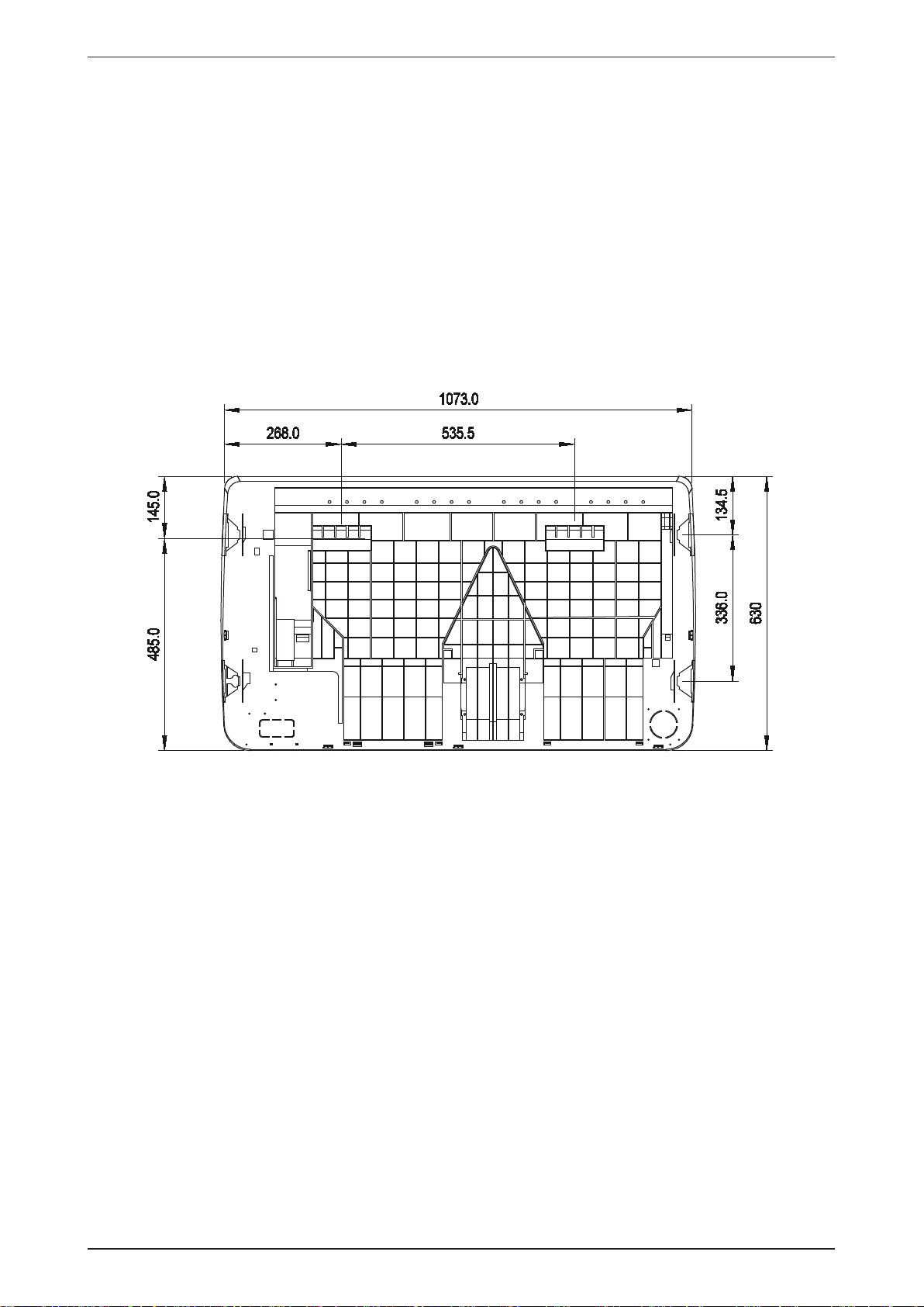
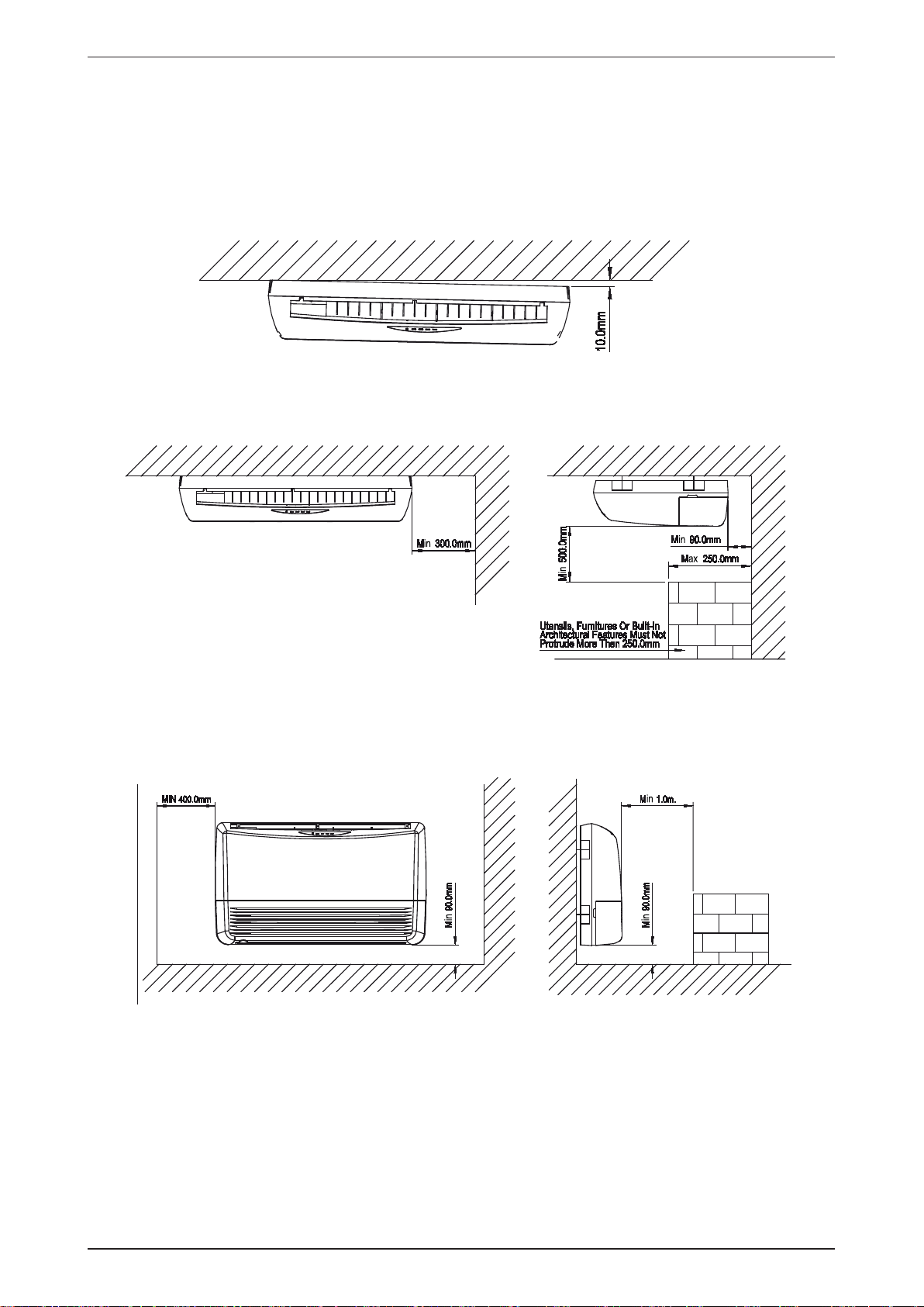
Indoor Unit
Model: M5CMY 15/20/25ER
Note: Dimension in mm
33
Page 36

M5MSY_(i) Wiring Diagram
Wiring Diagram
Outdoor Unit
Model: M5MSY18BR
Outdoor Unit
Model: M5MSY20BR
LED A Service monitor LED (green) SW3 Wiring error check switch
LED1 - LED4 Service monitor LED (red) SW4 Priority room setting switch
SW1 Forced operation ON/OFF switch SW5 Night quiet mode setting switch
34
Page 37

Wiring Diagram M5MSY_(i)
Outdoor Unit
Model: M5MSY25BR
Outdoor Unit
Model: M5MSY30BR
35
LED A Service monitor LED (green) SW3 Wiring error check switch
LED1 - LED4 Service monitor LED (red) SW4 Priority room setting switch
SW1 Forced operation ON/OFF switch SW5 Night quiet mode setting switch
Page 38

M5MSY_(i) Wiring Diagram
Indoor Unit
Model: M5WMY10/15JR/LR
Indoor Unit
Model: M5WMY20JR
36
Page 39

Wiring Diagram M5MSY_(i)
Indoor Unit
Model: M5CKY10/15/20CR
Indoor Unit
Model: M5CCY10/15CR
37
Page 40

M5MSY_(i) Wiring Diagram
Indoor Unit
Model: M5CCY20CR
Indoor Unit
Model: M5CMY15ER
38
Page 41

Wiring Diagram M5MSY_(i)
Indoor Unit
Model: M5CMY20ER
39
Page 42
M5MSY_(i) Service and Maintenance
Service and Maintenance
Warning
• Disconnect from main supply before servicing the air conditioner.
• The unit is designed to give long life operation with minimum maintenance required. However, it should be regularly
checked and the following items should be given due attention.
Components Maintenance Procedures Period
Air Filter
(Indoor Unit)
Indoor Unit 1. Clean any dirt or dust on the grille or panel by wiping it with a
Condense Drain
Pan & Pipe
Indoor Fan Check if there is any abnormal noise. If necessary.
Indoor / Outdoor
Coil
Power Supply 1. Check the running current and voltage for indoor and outdoor
Compressor No maintenance needed if refrigerant circuit remains sealed. How-
1. Remove any dust adhering to the fi lter by using a vacuum cleaner
or wash in lukewarm water (below 40˚C) with a neutral cleaning
detergent.
2. Rinse the fi lter well and dry before placing it back onto the unit.
At least once every 2
weeks.
More frequently if
necessary.
3. Note: Never use gasoline, volatile substances or chemicals to
clean the fi lter.
At least once every 2
soft cloth soaked in lukewarm water (below 40˚C) and a neutral
detergent solution.
2. Note: Never use gasoline, volatile substances or chemicals to
weeks.
More frequently if
necessary.
clean the indoor unit.
1. Check the cleanliness and clean it if necessary.
Every 3 months.
2. Check the condensate water fl ow.
1. Check and remove the dirt between the fi ns.
Every month.
2. Check and remove any obstacles which hinder air fl ow through
the indoor or outdoor.
3. Note: Avoid direct contact of any coil treatment material on the
plastic part. This may cause plastic part to deform as a result of
chemical reaction.
Every 2 months.
unit.
2. Check the electrical wiring and tighten the wire onto the terminal
Every year.
block if necessary.
Every 6 months.
ever, check for refrigerant leak at joint and fi tting.
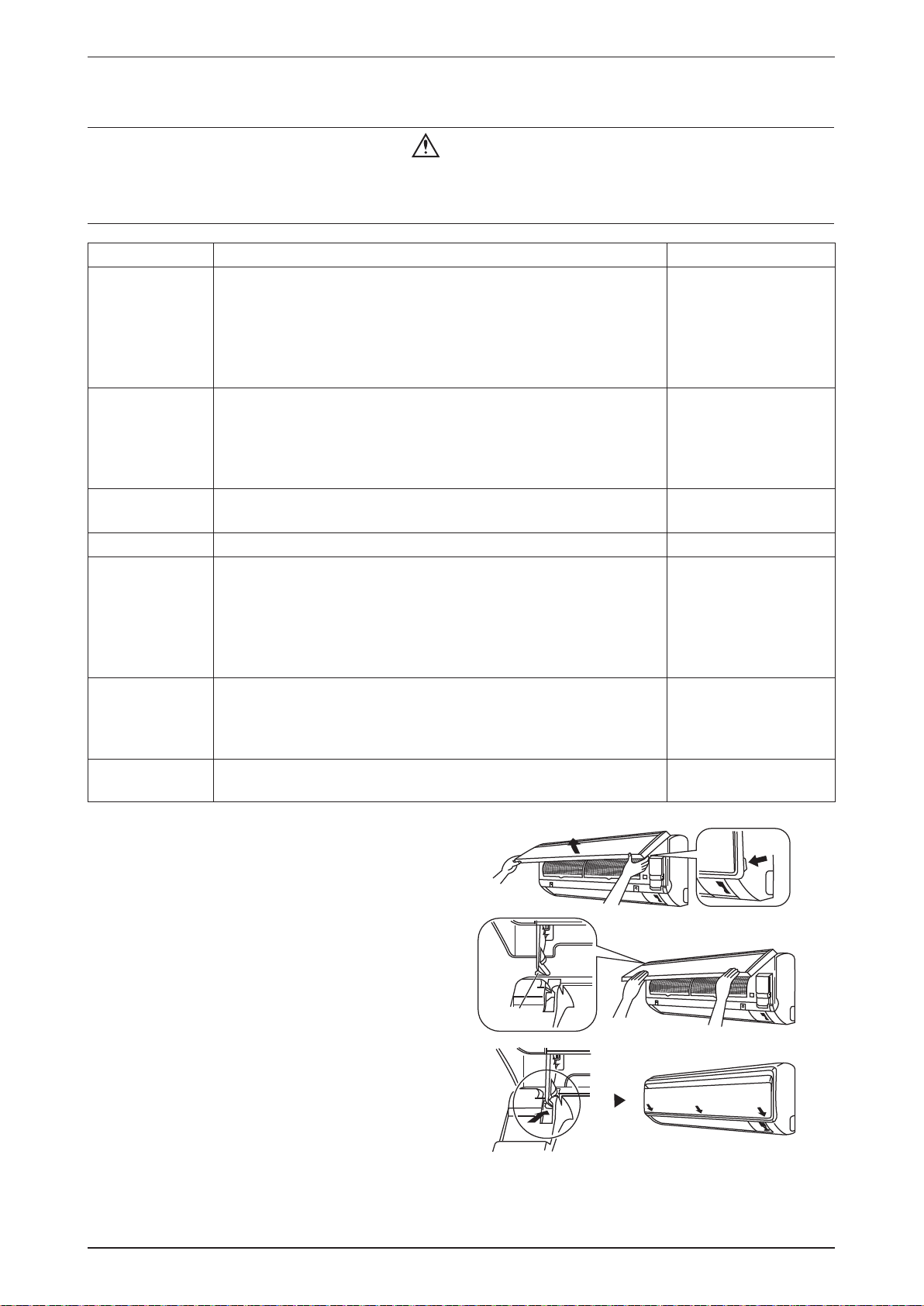
Indoor Models
1. Open the front panel
• Hold the panel at the recesses on the main unit
(2 recesses on right and left sides) and lift it until
it stops.
2. Remove the front panel
• While lifting the front panel further, slide it to the
right and pull it to the front side. The left rotating
shaft is detached. Slide the right rotating shaft to
the left and pull it to the front side to remove it.
3. Attach the front panel
• Align the right and left rotating shafts of the front
panel with the grooves and push them all the
way in.
• Gently close the front panel. (Push both ends
and the center on the front panel.)
Rotating
shaft
Recess on
main unit
40
Page 43

Service and Maintenance M5MSY_(i)
Air Filter
1. Open the front panel.
• Hold the panel at the recesses on the main unit (2 recesses on right and left sides) and lift it until it
stops.
Recess on
main unit
2. Pull out the air fi lters.
• Push a little upwards the tab at the center of each air fi lter, then pull it down.
3. Clean or replace each fi lter.
• When shaking off remaining water, do not wring the fi lter.
4. Set the air fi lter and close the front panel.
• Insert claws of the fi lters into slots of the front panel. Close the front panel slowly and push the panel at
the 3 points. (1 on each side and 1 in the middle.)
• The air fi lter have a symmetrical form in the horizontal direction.
FRONT
Caution
• Don’t touch the metal parts of the indoor unit. It may cause an injury.
• When removing or attaching the front panel, use a robust and stable stool and watch your steps carefully.
• When removing or attaching the front panel, support the panel securely with hand to prevent from it falling.
• For cleansing, do no use hot water above 40°C, benzene, gasoline, thinner, nor other volatile oils, polishing
compound, scrubbing brushes, nor other hand stuff.
• After cleaning, make sure that the front panel is securely fi xed.
Pre Start Up Maintenance
(After Extended Shutdown)
• Inspect thoroughly and clean indoor and outdoor units.
• Clean or replace air fi lters.
• Clean condensates drain line.
• Clean clogged indoor and outdoor coils.
• Check fan imbalance before operation.
• Tighten all wiring connections and panels.
• Check for refrigerant leakage.
Outdoor Models
The design of the M5MSY outdoor series allows servicing to be carried out easily. The removal of the top, front
and side panels makes almost every part accessible.
Under normal circumstances, these outdoor units only require a check and cleaning of air intake coil surface
once every 3 months. However, if a unit is installed in areas subjected to much oil mist and dust, the coils must
be regularly cleaned by qualifi ed Air Conditioner Service Technicians to ensure suffi cient heat exchange and
proper operation. Otherwise, the systems life span may be shortened.
Caution
• Do not charge OXYGEN, ACETYLENE OR OTHER FLAMMABLE and poisonous gases into the unit when
performing a leakage test or an airtight test. These gases could cause severe explosion and damage if exposed to
high temperature and pressure.
• It is recommended that only nitrogen or refrigerant be charged when performing the leakage or airtight test.
41
Page 44

M5MSY_(i) Troubleshooting
Troubleshooting
Fault Condition
When a malfunction of the air conditioner unit is detected, immediately switch off the main power supply before
proceeding with the following troubleshooting procedures.
The following are common fault conditions and simple troubleshooting tips. If any other fault conditions which
are not listed occur, contact your nearest local dealer. DO NOT attempt to troubleshoot the unit by yourself.
No Fault conditions Possible causes / corrective actions
1 The air conditioner unit will not resume after
power failure.
2 The airfl ow is too slow or room cannot be
cooled suffi ciently.
3 Discharge airfl ow has bad odor. • Cigarettes, smoke particles, perfume and
4 Condensation on the front air grille of the indoor
unit.
5 Water fl owing out from the air conditioner. • Switch off the unit and contact your nearest
6 Hissing airfl ow sound from the air conditioner
unit during operation.
7 The wireless controller display is dim. • The batteries are discharged.
8 Compressor operates continuously. • Dirty air fi lter. Clean the air fi lter.
9 No cool air comes out during cooling cycle, or
no hot air comes out during heating cycle.
10 On heating cycle, warm air does not come out. • Unit is in defrost mode. Heating operation will
• The auto restart function is not functioning.
Please turn on the unit with the wireless /
wired controller.
• The air fi lter is dirty.
• The doors and windows are opened.
• The air suction and discharge of both indoor
and outdoor units are clogged or blocked.
• The regulated temperature or temperature
setting is not low enough.
others, which might have adhered onto the
coil, may cause odor.
• Contact your nearest dealer.
• This is caused by air humidity after an
extended period of operation.
• The set temperature is too low. Increase the
temperature setting and operate the unit at
high fan speed.
dealer. This might be due to tilted installation.
• Liquid refrigerant fl owing into the evaporator
coil.
• The batteries are not correctly inserted.
• The assembly is not good.
• Temperature setting too low (cooling). Use
higher temperature setting.
• Temperature setting too high (heating). Use
lower temperature setting.
• Temperature setting too high (cooling). Use
lower temperature setting.
• Temperature setting too low (heating). Use
higher temperature setting.
resume after defrost cycle ends.
42
Page 45

Troubleshooting M5MSY_(i)
Indicator Lights
IR Signal Receiver
When an infrared remote control operating signal has been transmitted, the signal receiver on the indoor unit
will respond as below to confi rm acceptance of the signal transmission.
ON to OFF 1 Long Beep
OFF to ON
Pump down/Cool force on
2 Short Beep
Others 1 Short Beep
Heat Pump Unit
The table shows the LED indicator lights for the air conditioner unit under normal operation and fault conditions.
The LED indicator lights are located at the side of the air conditioner unit.The heat pump units are equipped
with an “auto” mode sensor whereby it will provide reasonable room temperature by switching automatically to
either “cool” or “heat” mode according to the temperature set by the user.
Model
5WMY 10/15 LR
5WMY 10/15/20 JR
5CKY 10/15/20 CR
5CMY 20ER
5CCY 20CR
ON/OFF
IR Receiver
Cool / Heat
Timer
Sleep
ON/OFF switch
LED Indicator Lights: Normal Operation and Fault Conditions for Heat Pump Unit
(RED)
1
COOL/HEAT
(GREEN/RED)
Green
Red
Red
Green
(ORANGE)
Normal Operation / Fault Indication
Cool mode
Heat mode
Auto mode in Heating operation
Auto mode in Cooling operation
Time off (when unit is on)
Time on (when unit is off)
Sleep mode on
Green
Green
Fan mode on
Dry mode on
43
Red
Green
ON Blinking
Defrost operation
Error indication
Page 46
M5MSY_(i) Troubleshooting
Error Code Diagnosis by Wireless Handset GS01
TURBO QUIET
ON TIMER CANCEL
SLEEP
ON OFF
CANCEL
TIMER
CLOCK
MODE
CANCEL
OFF TIMER CANCEL
Diagnosis Step
1. Hold down ON TIMER CANCEL button or OFF TIMER CANCEL button for 5 seconds, a “ ” indication
fl ashes on the temperature display section.
2. Press ON TIMER CANCEL or OFF TIMER CANCEL repeatedly until indoor buzzer produces a long beep.
This indicates the error code, refers to Error Codes table and is displayed on the temperature display
section.
3. A short beep or two consecutive beeps indicate non-corresponding error codes.
4. To cancel the error code display, hold down ON TIMER CANCEL or OFF TIMER CANCEL button for 5
seconds. Alternatively, the code display will cancel itself if the button is not pressed for 1 minute.
Error Code Diagnosis by Wired Handset Netware 3C
44
Page 47
Troubleshooting M5MSY_(i)
Error Codes
Error
Codes
U0 Insuffi cient gas
U2 DC voltage out of range
U4 Communication error
U7
UA Installation error
UF
UH Anti-freeze function in other room
A1 Indoor PCB error
A3 Water pump error
A5 Antifreeze
A6 Indoor fan motor abnormal
C4
C9 Indoor room thermistor short/open
E1 Outdoor PCB error
Error Description Action
0 Normal No action.
1. Check sensor connection.
2. Check stop valve.
3. Check for gas leak.
4. Check the EXV.
5. Check H8.
1. Check the supply voltage.
2. Check the outdoor fan by rotating with hand.
3. Restart the system.
4. Check power supply waveform.
1. Check the indoor unit - outdoor unit connection wires.
2. Check the voltage of the signal terminal.
3. Check the indoor fan by rotating with hand.
4. Check the power supply waveform.
Signal transmission error (on outdoor unit PCB)
Communication Error (indoor and
outdoor) piping and wiring
Indoor heat exchanger
thermistor short/ open
1. Restart the system.
2. Replace outdoor PCB.
3. Long term monitor on external factor.
1. Check the indoor and outdoor unit model name.
2. Check the part code on the indoor and outdoor PCB.
1. Check the wiring and piping between indoor and outdoor units.
2. Check refrigerant level.
3. Check refrigerant line on blockage.
1. Check which indoor having error A5.
2. Check the supply voltage.
3. Check the indoor and outdoor model name.
1. Check connector connection.
2. Replace indoor PCB.
1. Check for short circuit.
2. Check connection on drain pump.
3. Restart the system.
4. Check the drain water level.
5. Check fl oat switch connection.
1. Check the air passage.
2. Check the intake air fi lter.
3. Check dust accumulation on indoor coil.
4. Check wiring and piping.
5. Check the EXV.
6. Check indoor coil sensor resistance value.
7. Check refrigerant level.
8. Check room sensor resistance value.
1. Check the indoor fan by rotating with hand.
2. Replace indoor fan motor if not rotating smoothly.
3. Check fan motor voltage.
4. Replace indoor PCB if not at the rated voltage.
5. Check fan capacitor's conductivity (AC Motor).
6. Replace fan capacitor if there's conductivity.
1. Check the connector connection.
2. Check the sensor resistance value.
1. Restart the system.
2. Replace outdoor PCB.
3. Check to see that the unit is grounded.
4. Check power supply waveform.
45
Page 48
M5MSY_(i) Troubleshooting
Error
Codes
E3 High pressure protection
E4 Low pressure protection
E5 Compressor motor lock/overload
E6 Compressor lock/start-up error
E7 Outdoor DC fan motor lock
E8 Ac input over current
E9 EXV error
EA 4-way valve error
F3 Discharge pipe overheat
F6 Heat exchanger overheat
H0
H3 High pressure switch error
H6 Position sensor abnormality
Error Description Action
Compressor sensor system abnormality
1. Check installation conditions.
2. Check stop valve.
3. Check HPS connection.
4. Check pressure level by pressure gauge.
5. Wait for 10 minutes then restart the system.
6. Check if H3 is displayed.
1. Check stop valve.
2. Check low pressure sensor connection.
3. Check low side pressure and voltage.
4. Check outdoor coil sensor connection.
5. Check sensor resistance value.
6. Check refrigerant level.
1. Check connection on discharge pipe sensor.
2. Check discharge pipe sensor resistance value.
3. Check the EXV.
4. Check the refrigerant line on blockage or shortage.
1. Check with inverter checker.
2. Check the EXV.
1. Check the fan motor connection.
2. Check if foreign matters exist around or in the fan.
1. Measure the input current.
2. Check the main circuit electrolytic capacitor.
3. Check with inverter checker.
4. Check discharge pressure.
5. Check the installation condition.
1. Restart the system.
2. Check the EXV connection.
3. Check EXV coil resistance.
4. Check sensors resistance value.
1. Check 4WV coil connection.
2. Check the continuity of the 4WV coil and harness.
3. Check the 4WV switching output.
4. Check sensor connection.
5. Check sensor resistance value.
6. Check the refrigerant line on blockage or shortage.
1. Check the discharge pipe sensor.
2. Check the EXV.
3. Check the refrigerant line on blockage or shortage.
1. Check the installation space.
2. Check the outdoor fan.
3. Check the EXV.
4. Check the coil sensor.
1. Check the reactor connection.
2. Check the compressor connection.
3. Measure the resistance value between the reactor terminals.
4. Measure the resistance value between the compressor terminals.
1. Check pressure sensor connection.
2. Check HPS continuity.
1. Check for short circuit.
2. Check the electrolytic capacitor voltage.
3. Check compressor harness wire.
4. Check with inverter checker.
46
Page 49

Troubleshooting M5MSY_(i)
Error
Codes
H8 AC current sensor error
H9 Outdoor air thermistor short / open
J1 Pressure sensor error
J3
J5 Suction pipe thermistor short/ open Same as H9.
J6 Outdoor heat exchanger Same as H9.
J7
J8 Liquid pipe thermistor short/ open Same as H9.
J9 Gas pipe thermistor abnormality Same as H9.
LC
L1 Outdoor PCB error
L3 Electrical box temperature rise
L4 Heat sink overheat
L5 IPM error / IGBT error
L8 Electrical thermal switch Contact dealers for assistance.
L9 Stall prevention
P1 Open phase or voltage unbalance
P4 Heat sink thermistor short / open Same as H9.
PJ Capacity setting error 1. Check the connection between capacitor and Outdoor PCB.
Error Description Action
1. Restart the system.
2. Check capacitor voltage.
3. Measure the rectifi er input voltage.
4. Check compressor harness wire.
5. Check with inverter checker.
1. Check the sensor connection.
2. Check the sensor resistance value.
1. Check pressure sensor connection.
2. Check pressure and voltage level.
Compressor discharge pipe thermistor short /open / misplaced
Subcooling heat exchanger
thermistor short/ open
Communication Error (control PCB
and inverter PCB)
1. Check the sensor connection.
2. Check the sensor resistance value.
3. Check indoor coil sensor resistance value.
Same as H9.
1. Check fan motor connection.
2. Check if LED blinking normally at outdoor PCB.
1. Check the range of power supply.
2. Check connection between compressor and PCB.
3. Check fan motor resistance.
4. Check the power supply waveform.
1. Restart the system.
2. Check sensor resistance value.
3. Check heat sink temperature and conditions.
4. Check outdoor fan.
5. Check the installation condition.
1. Restart the system.
2. Check the silicon grease condition on heat sink.
3. Check sensor resistance value.
4. Check heat sink temperature and conditions.
5. Check outdoor fan.
6. Check the installation condition.
1. Check stop valve.
2. Check with inverter checker.
3. Check the power transistor.
4. Check the supply voltage.
5. Check the compressor phase.
6. Check the discharge pressure.
7. Check the installation condition.
1. Check installation conditions.
2. Check stop valve.
3. Check difference between high and low pressure side.
4. Check continuity on the power transistor.
5. Check the output voltage.
1. Check LED on outdoor PCB.
2. Check open phase of power supply voltage.
3. Check voltage balance between phases.
47
Page 50
M5MSY_(i) Troubleshooting
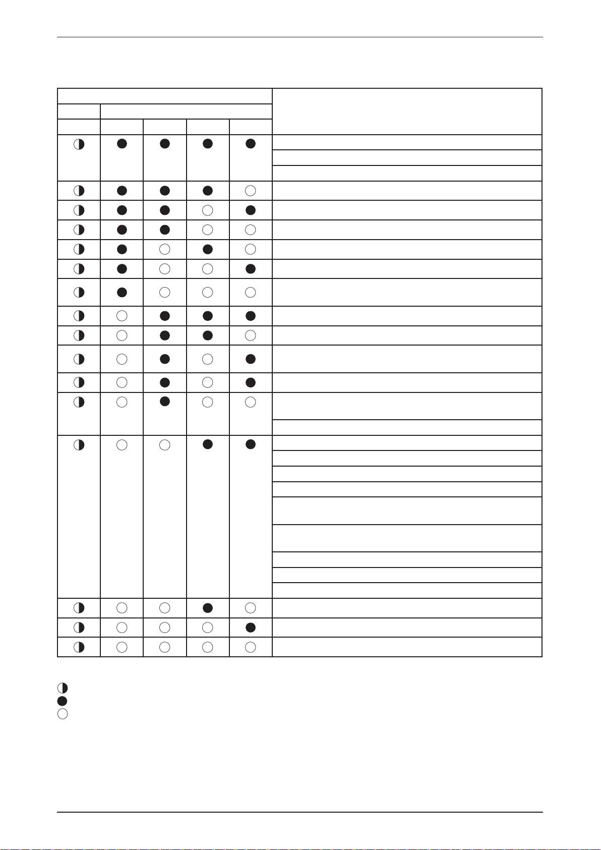
Outdoor LED error indication
The outdoor unit LED indicates the running condition of the system:
LED INDICATION
DescriptionGreen Red
A1234
NORMAL
INSTALLATION ERROR
ANTIFREEZE (OTHER ROOMS)
HEAT SINK OVERHEAT
IPM ERROR/IGBT ERROR
INSUFFICIENT GAS
AC INPUT OVER CURRENT
COMPRESSOR START-UP ERROR
COMMUNICATION ERROR (OUTDOOR CONTROL PCB
AND IPM PCB)
4 WAY VALVE ERROR
DC VOLTAGE OUT OF RANGE
COMPRESSOR MOTOR LOCK/COMPRESSOR OVERLOADED
DISCHARGE PIPE OVERHEAT
ANTIFREEZE (COOLING)/HEAT EXCHANGER OVERHEAT (HEATING)
HEAT EXCHANGER OVERHEAT
COMPRESSOR SENSOR SYSTEM ERROR
COMPRESSOR FEEDBACK DETECTION ERROR
AC CURRENT SENSOR ERROR
OUTDOOR AIR THERMISTOR SHORT/OPEN
COMPRESSOR DISCHARGE PIPE THERMISTOR
SHORT/OPEN/MISPLACED
COMPRESSOR DISCHARGE PIPE THERMISTOR
SHORT/OPEN/MISPLACED
LIQUID PIPE THERMISTOR SHORT/OPEN
GAS PIPE THERMISTOR SHORT/OPEN
HEAT SINK THERMISTOR SHORT/OPEN
OUTDOOR CONTROL BOX OVERHEAT
OUTDOOR PCB ERROR
OUTDOOR DC FAN MOTOR LOCK
Legend
Blinks
Off
On
If faulty condition occurs, please contact the nearest local dealer or qualifi ed service personnel. Do not attempt
to troubleshoot the unit yourself. For any enquiries on spare parts please contact your authorized dealer.
48
Page 51

Troubleshooting M5MSY_(i)
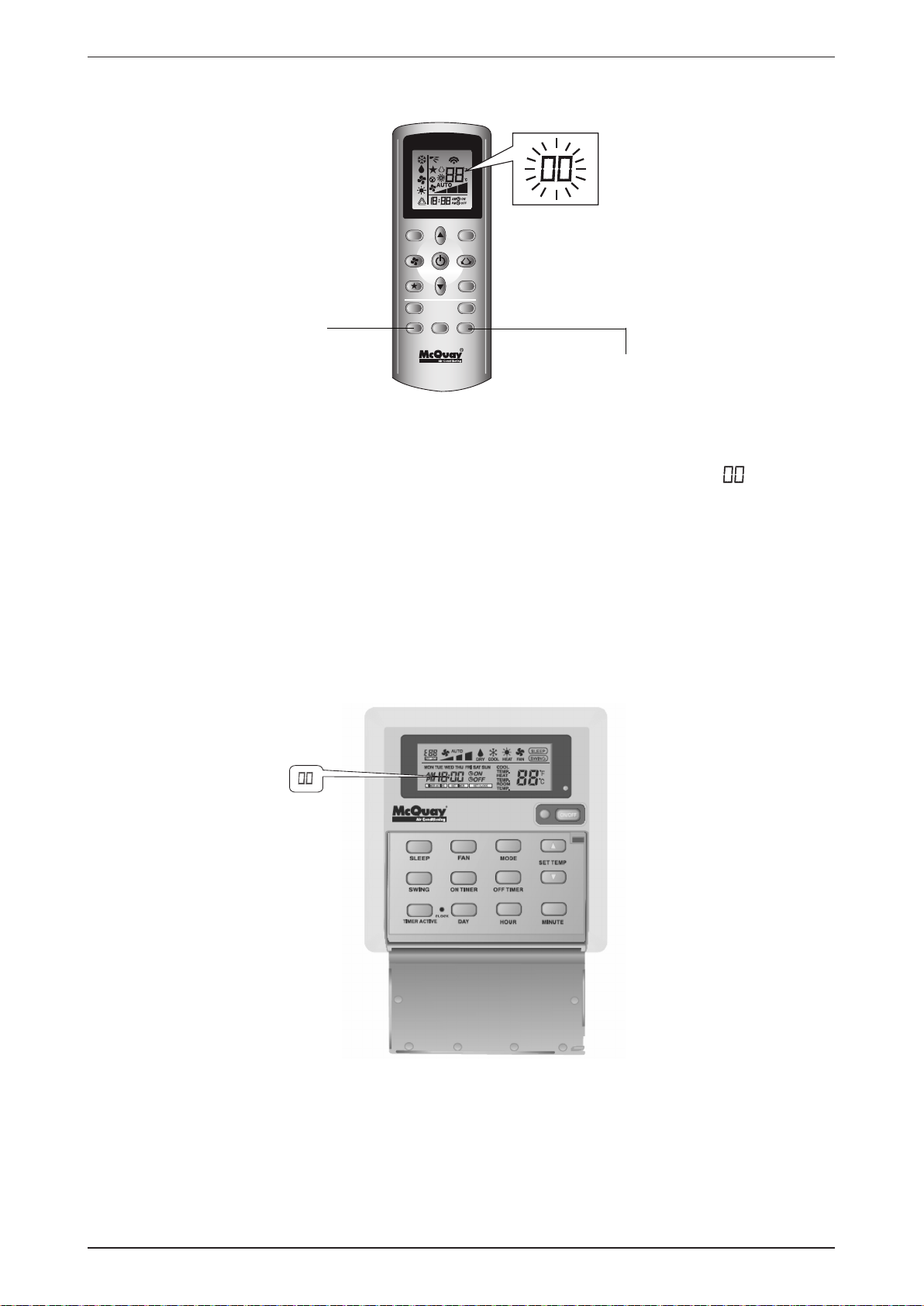
Error Code Diagnosis by Unit Last State Memory Using Wireless Handset
1. Remove battery from wireless handset.
2. Wait for the display to fi nally go off (as this handset uses very small amount of power, hence it takes
longer for the memory to reset).
3. Replace battery again and immediately (before display comes back on the LCD screen), press on Mode
and ON/OFF buttons together until you see “00” is being displayed.
4. Press Mode button to 5:00.
5. Press ON/OFF button once.
6. After that, remove battery from wireless handset and wait until the display has gone off. Then, replace
battery again into the handset.
7. Finally, repeat the fault diagnosis steps by wireless handset GS01 above.
Error Code Diagnosis by Unit Last State Memory Using Wired Handset
1. Press SLEEP and TIMER ACTIVE buttons together until error code starts fl ashing on the last 2 digits of
the clock display area.
49
Page 52

M5MSY_(i) Exploded View and Part List
Exploded View and Part List
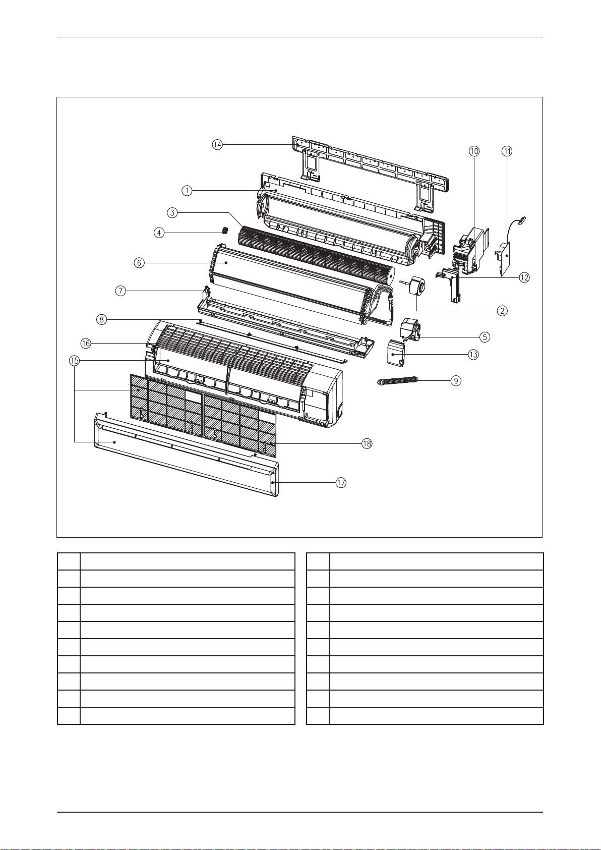
Indoor Unit
Model: M5WMY10/15LR
No
Description
1 Assy. Front Grille
2 Assy. Panel
3 Assy. Disch. Grille Hor.Blade
4 Bottom Frame Assy.
5 Assy. Control Box
6 Assy. Service Cover
7 Assy. Piping Fixture
8 Motor
9 Motor Mounting Plate (1)
10 Motor Mounting Plate (2)
11 Blower, Cross Flow
Note: All exploded view and part list are subjected to change by the manufacturer without prior notice
No
Description
12 Assy. Installation Plate
13 Right Side Panel
14 Drip Proof Cover
15 Clip, Coil Sensor
16 Assy. Coil
17 Assy. Drain Hose
18 Fan Bearing Vibration Absorber Set
19 Air Filter
20 Handset, Wireless
21 Assy. PCB (With Lamp Cover)
50
Page 53

Exploded View and Part List M5MSY_(i)
Indoor Unit
Model: M5WMY10/15JR
16
15
14
13
11
8
12
18
4
3
1
2
No
Description
1 Assy. Front Grille
No
Description
11 Blower
10
9
17
7
20
5
6
19
2 Panel
3 Disch. Grille Hor. Blade Assy.
4 Assy. Bottom Frame
5 Assy. Control Box
6 Assy. Service Cover
7 Assy. Piping Fixture
8 Motor
9 Motor Mounting Plate (1)
10 Motor Mounting Plate (2)
12 Assy. Installation Plate
13 Right Side Panel
14 Cover, Drip Proof
15 Clip, Coil Sensor
16 Assy. Heat Exchanger
17 Assy. Drain Hose
18 Fan Bearing Vibration Absorber
19 Air Filter
20 Assy. Control Module
Note: All exploded view and part list are subjected to change by the manufacturer without prior notice
51
Page 54
M5MSY_(i) Exploded View and Part List
Indoor Unit
Model: M5WMY 20JR
No Description
1
Assy. Chasis
2
Motor
3
Blower
4
Fan Bush
5
Cover, Motor
6
Assy. Heat Exchanger
7
Assy. Air Discharge Housing
8
Assy. Louver
9
Hose
Note: All exploded view and part list are subjected to change by the manufacturer without prior notice
No Description
10
Assy. Control Box
11
Assy. Control Module
12
Cover, Control Box
13
Cover, Service
14
Assy. Mounting Plate
15
Assy. Front Cover
16
Cover, Front
17
Intake Grille
18
Filter
52
Page 55

Exploded View and Part List M5MSY_(i)
Indoor Unit
Model: PLCKY-CR
No Description
1
Frame
2
Assy. Intake Grille B
3
Filter
4
Lock, Grille
5
Discharge, Foam
6
Discharge, Foam LED
7
Discharge, Foam Short
8
Louver
9
Louver, LED
10
Lingkage, Cover
Note: All exploded view and part list are subjected to change by the manufacturer without prior notice
No Description
11
Lingkage, Motor Cover
12
Assy. Bracket Receiver (LED/SLM)
13
Assy. Motor
14
Crank, Connector
15
Louver, Holder
16
Cross, Crank
17
Ins. Long
18
Ins. Short
19
Ins. Corner
53
Page 56

M5MSY_(i) Exploded View and Part List
Indoor Unit
Model: M5CKY 10/15/20CR
Note: All exploded view and part list are subjected to change by the manufacturer without prior notice
54
Page 57

Exploded View and Part List M5MS_(i)
Indoor Unit
Model: M5CKY 10/15/20CR
No Description
1
Assy. Base
2
Assy. Casing
3
Assy. Heat Exchanger
4
Cover, Fan
5
Blower
6
Plate, Wire
7
Motor
8
Bush, Motor
9
Bush, Motor Ring
10
Assy. Control Box
11
Pump, Water
12
Switch, Water Level
13
Bush, Wire
No Description
14
Bush, Pump
15
Assy. Drain Pump Support Bracket
16
Assy. End Plate Support
17
Clip, Coil Sensor
18
Support, Heat Exchanger
19
Cover, Terminal
20
Assy. Cover Wire
21
Connector, Drain
22
Hose, Drain
23
Assy. Cover Valve
24
Assy. Drain Pan
25
Bush, Wire
26
Cover, Wire Bracket
Note: All exploded view and part list are subjected to change by the manufacturer without prior notice
55
Page 58

M5MSY_(i) Exploded View and Part List
Indoor Unit
Model: M5CCY 10/15/20CR
No Description
1
Cabinet
2
Assy. Fan Deck
3
Assy. Heat Exchanger
4
Assy. Drain Pan
5
Assy. Secondary Drain Pan
6
Hanger
7
Control Module
8
Assy. Blower Right
Note: All exploded view and part list are subjected to change by the manufacturer without prior notice
No Description
9
Assy. Blower Left
10
Motor
Parts Not in Diagram
Handset, Wired
Air Filter
Holder, Thermistor
Clip, Coil Sensor
56
Page 59
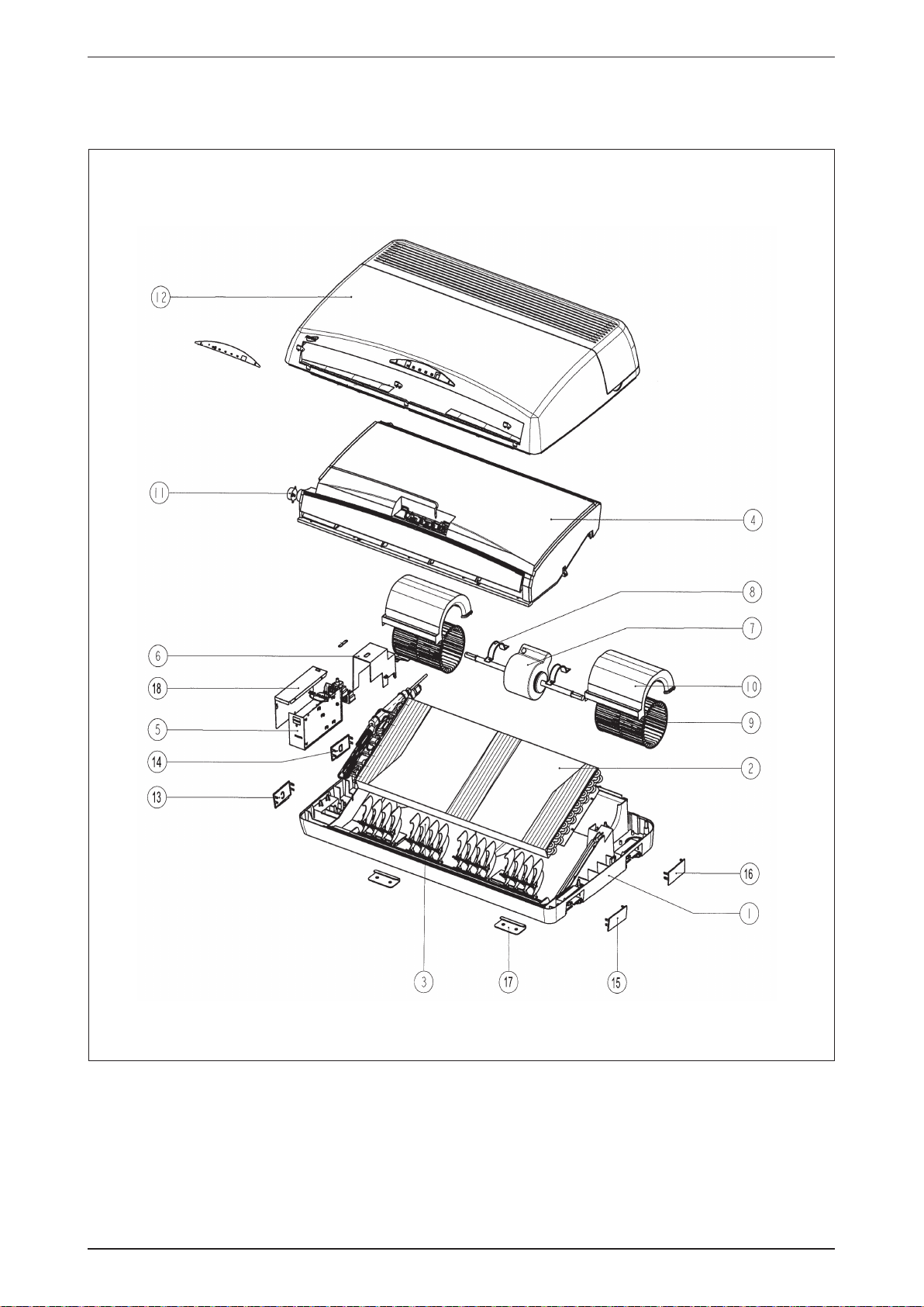
Exploded View and Part List M5MSY_(i)
Indoor Unit
Model: M5CMY 15/20ER
ote: All exploded view and part list are subjected to change by the manufacturer without prior notice
57
Page 60
M5MSY_(i) Exploded View and Part List
Indoor Unit
Model: M5CMY 15/20/25ER
No Description
1
Assy. Top Panel
2
Assy. Heat Exchanger
3
Assy. Vane
4
Assy. Drain Pan
5
Assy. Control Box
6
Terminal Box Cover
7
Motor
8
Bracket, Motor
9
Blower
10
Housing, Blower
11
Motor, Louver
No Description
12
Assy. Panel Bottom
13
Cover, Hanger L1 (C)
14
Cover, Hanger L2 (D)
15
Cover, Hanger R1 (A)
16
Cover, Hanger R2 (B)
17
Bracket, Mounting
18
Control Box Cover
Parts Not in Diagram
Handset, Wireless
Control Module
Intake Grille
Note: All exploded view and part list are subjected to change by the manufacturer without prior notice
58
Page 61
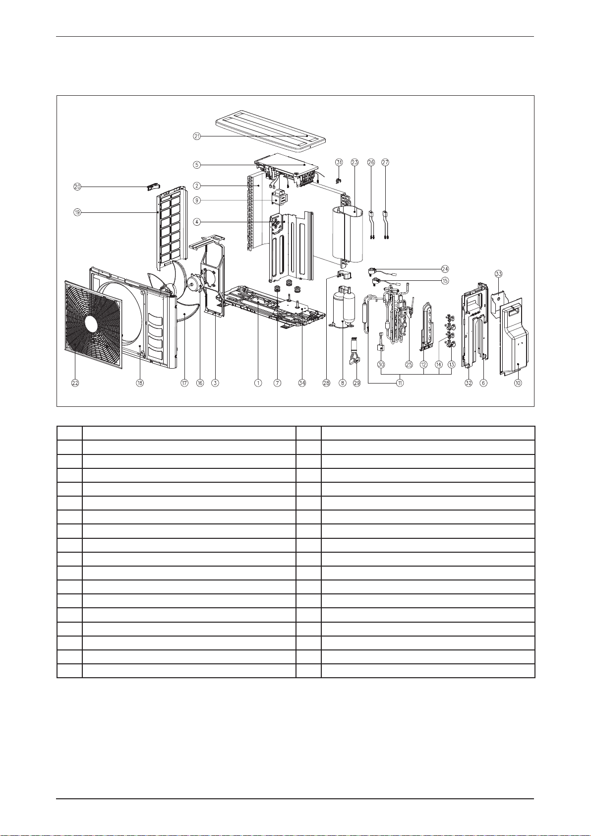
Exploded View and Part List M5MSY_(i)
Outdoor Unit
Model: M5MSY18BR
No Description No Description
1 Assy. Bottom Frame 18 Panel, Front 5SLY10/15D
2 Assy. Coil 5SLY15D/DR (Complete) 19 Left Side Plate (1P205165-1)
3 Assy. Motor Bracket 20 Handle (Left) 3P206051-1
4 Panel, Partition 21 Top Plate (2P206032-1)
5 Assy. Control Box (Main) 5MSY18BR 22 Front Grille 5SLY10/15D
6 Service Panel 23 Compressor Felt
7 Grommet, Compressor 3PB39152H (Dalian) 24 Solenoid Coil, CAM12DM-28 (3SB45505-2)FJ
8 Compressor, 1YC23AGXD Daikin 25 Putty (T5.0 x 105.0 x 50.0mm)
9 Reactor, 3EB75117C 18MH 10A 26 Assy. Thermistor Gas (4P182128-1)
10 Stop Valve Cover (1P206153-1) 27 Assy. Thermistor Liquid (4P182129-1)
11 Assy. Tubing (5MSY18BR) 28 Terminal Cover, Daikin 2YC (3PD03148-1)
12 Valve Plate 29 Assy. Compressor Wire
13 Valve, Flare 3 Way ⅜″ 30 Assy. Solenoid Coil
14 Valve, Flare 2 Way ¼″ 31 Thermister Holder WM20/25G
15 Solenoid Coil, ZCAM12FKTH-XN-A, FJ 32 Push Releasable Tie 1686 S452002H01
16 Motor, M5MSY18BR-1, 50W, 300VDC 33 Radiation Shield Plate (3P205745-1)
17 Fan Propeller, 400mm 2P183614-2 Kohbunshi 34 Assy. Comp. Mounting Plate
Note: All exploded view and part list are subjected to change by the manufacturer without prior notice
59
Page 62

M5MSY_(i) Exploded View and Part List
Outdoor Unit
Model: M5MSY20BR
No Description No Description
1 Assy. Base Pan 14 Assy. Comp. Mounting Plate
2 Assy. Outdoor Coil 15 Grommet, Comp.
3 Flat Washer 16 Compressor
4 Washer, Spring 17 Terminal Cover
5 Screw 18 Motor, Bracket
6 Assy. Panel Right Back 19 Plate, Seal Board
7 Assy. Panel Top 20 Assy. Valve Plate Main
8 Plastic, Handle 21 Assy. 4WV
9 Partition 22 Panel, Service
10 Assy. Control Box 23 Plastic, Front Grille
11 Assy. Propeller Fan 24 Plastic, Valve Cover
12 Motor 25 Access, Cover
13 Panel, Front/ Left 26 Compressor, Felt
Note: All exploded view and part list are subjected to change by the manufacturer without prior notice
60
Page 63

Exploded View and Part List M5MSY_(i)
Outdoor Unit
Model: M5MSY25BR
No Description No Description
1 Assy. Base Pan 15 Grommet, Comp.
2 Assy. Outdoor Coil 16 Accumulator
3 Flat Washer 17 Compressor
4 Washer, Spring 18 Terminal Cover
5 Screw 19 Motor, Bracket
6 Assy. Panel Right Back 20 Plate, Seal Board
7 Assy. Panel Top 21 Assy. Valve Plate Main
8 Plastic, Handle 22 Assy. 4WV
9 Partition 23 Panel, Service
10 Assy. Control Box 24 Plastic, Front Grille
11 Assy. Propeller Fan 25 Plastic, Valve Cover
12 Motor 26 Access, Cover
13 Panel, Front/ Left 27 Compressor, Felt
14 Assy. Comp. Mounting Plate
Note: All exploded view and part list are subjected to change by the manufacturer without prior notice
61
Page 64
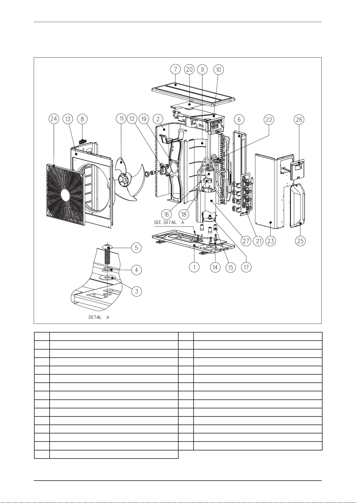
M5MSY_(i) Exploded View and Part List
Outdoor Unit
Model: M5MSY30BR
No Description No Description
1 Assy. Base Pan 15 Grommet, Comp.
2 Assy. Outdoor Coil 16 Accumulator
3 Flat Washer 17 Compressor
4 Washer, Spring 18 Terminal Cover
5 Screw 19 Motor, Bracket
6 Assy. Panel Right Back 20 Plate, Seal Board
7 Assy. Panel Top 21 Assy. Valve Plate Main
8 Plastic, Handle 22 Assy. 4WV
9 Partition 23 Panel, Service
10 Assy. Control Box 24 Plastic, Front Grille
11 Assy. Propeller Fan 25 Plastic, Valve Cover
12 Motor 26 Access, Cover
13 Panel, Front/ Left 27 Compressor, Felt
14 Assy. Comp. Mounting Plate
Note: All exploded view and part list are subjected to change by the manufacturer without prior notice
62
Page 65

Products manufactured in an ISO certified facility.
This document contains the most current product information as of this printing. For the
most up-to-date product information, please go to www.mcquayup.com
© 2011 McQuay International www.mcquayup.com
Page 66

Revision History List
Manual : Inverter Multi Split System TM : M5MSY_(i)-0001
Revision Subject
01 1. Correction on Application Information 19 09.1.2012
Amendment on
Manual’s Page No.
Date
 Loading...